

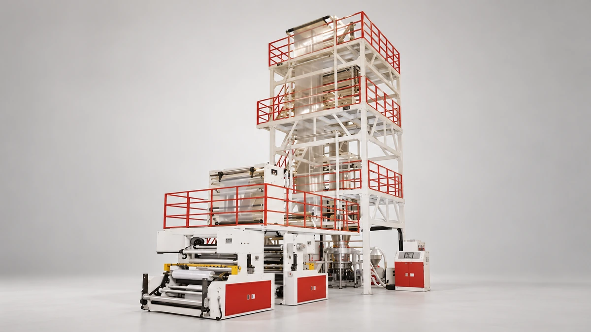
Understanding Blown Film Defects and Why They Matter
Blown film defects are any deviations from target film quality that occur during the blown film extrusion process. They span the entire spectrum of film characteristics — visual blemishes like gels and die lines, dimensional failures such as gauge variation and uneven layflat width, mechanical shortfalls including poor dart impact and low elongation, and optical flaws like haze and reduced clarity. If the finished film doesn't meet the converter's specification sheet, something went wrong between hopper and winder — and that "something" is a defect waiting to be diagnosed.
Why does this matter beyond the obvious? Because in high-speed packaging film production, even a small, recurring defect cascades into hours of scrap, rejected shipments, and costly downtime. A single unstable bubble doesn't just waste material — it stalls an entire line. Multiply that across shifts and weeks, and the impact on yield, cost-per-meter, and customer confidence becomes staggering. Operators who can identify and resolve these issues quickly protect both margins and relationships with downstream converters who depend on consistent incoming film quality.
What Counts as a Blown Film Defect
The scope is broader than most operators initially assume. Surface blemishes — think melt fracture, fisheyes, orange peel texture, and contamination specks — are the defects you can see and feel. Gauge variation, whether in the machine direction or transverse direction, falls into the dimensional category and often goes unnoticed until a printing press or bag-making machine exposes the inconsistency. Bubble instability, including sway, breathing, and helical motion, produces continuous scrap for as long as it persists. Poor optical clarity, weak seal strength, and brittleness round out the mechanical and performance categories. Each of these defect families behaves differently, originates in a different zone of the extrusion line, and demands a different corrective approach.
Here is a practical way to think about the major defect families:
- Surface and optical defects — gels, die lines, haze, melt fracture, fisheyes, and roughness
- Dimensional defects — gauge bands, thickness variation, inconsistent blow up ratio, and uneven layflat
- Stability defects — bubble sway, breathing, draw resonance, and helical instability
- Mechanical property defects — low dart impact, poor tear strength, brittleness, and weak seals
- Equipment-origin defects — screw wear marks, contamination streaks, and heater-band hot spots
- Multi-layer-specific defects — delamination, encapsulation, and interlayer distortion
Why a Systematic Approach Beats Random Troubleshooting
Imagine this scenario: haze suddenly appears on your film mid-shift. One operator lowers the melt temperature. Another adjusts the air ring. A third suspects the resin lot. Three people, three different guesses, three simultaneous changes — and nobody learns what actually caused the problem, even if it temporarily disappears. This trial-and-error instinct is natural, but it's expensive. Experienced operators take a different path. They use elimination-based logic, starting with the defect's category and tracing it backward through the process zones to narrow the root cause before touching a single dial.
The fastest fix starts with correctly categorizing the defect — surface, dimensional, mechanical, or stability — before touching any process setting.
Most blown film defects trace back to one of three root cause categories: resin-related (lot-to-lot variation, contamination, moisture absorption), equipment-related (screw and barrel wear, die damage, air ring imbalance), or process-parameter-related (temperature profiles, line speed, pressure settings). Learning to triage a defect into the right category is the single most important first step. A resin-driven defect won't respond to a die adjustment. An equipment wear problem won't improve with a temperature change. And a parameter error won't disappear with a new resin lot. The diagnostic sequence matters — and throughout this guide, you'll learn to follow it like a defect detective working a case from evidence to root cause to permanent fix.
That triage, however, only works when you can accurately name the defect you're looking at. A gel and a fisheye can appear nearly identical on a fast-moving web, yet they demand completely different corrective actions. Misidentify one, and you'll chase the wrong solution for an entire shift. That's exactly why building a complete defect taxonomy — a structured classification of every blown film defect by category, origin, and urgency — is the essential next step.
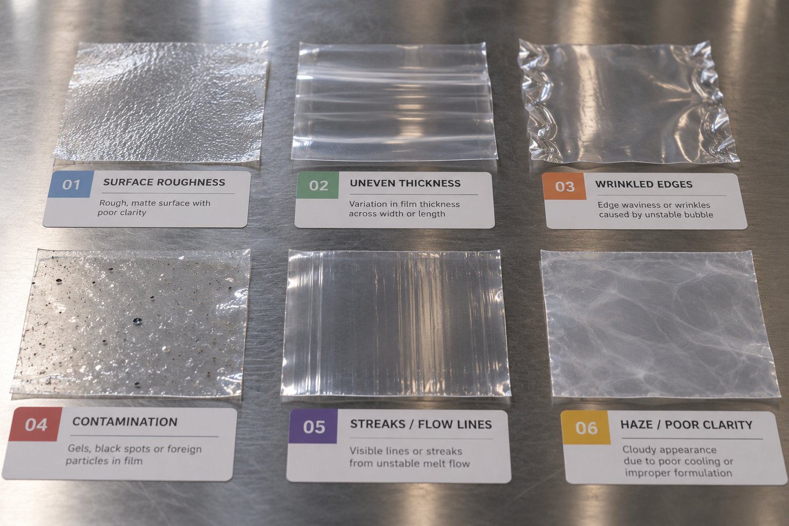
A Complete Blown Film Defect Taxonomy
A defect you can't name is a defect you can't fix efficiently. Before jumping into root causes, you need a reliable classification system — one that groups every problem by its nature, tells you where on the line it most likely originates, and flags how urgently you need to respond. Think of this taxonomy as a triage card for your extrusion line. Print it, laminate it, and post it where every operator can reach it mid-shift.
The taxonomy below breaks blown film defects into six distinct families. The first three — surface and optical, dimensional and gauge, and bubble stability and mechanical — account for the vast majority of day-to-day issues. Two additional groups cover equipment-origin and multi-layer-specific defects, which are less frequent but no less costly when they appear.
Surface and Optical Defects
Surface defects are the most immediately visible problems on a blown film web, and they almost always originate between the screw tip and the die exit. Die lines — those persistent thin streaks running in the machine direction — typically point to die lip damage, contamination buildup, or improper bolt adjustment. Melt fracture, sometimes called sharkskin, creates a rough, ridged texture caused by excessive shear stress at the die land. It becomes especially common when processors push output rates beyond a resin's critical shear threshold.
Gels and fisheyes look similar to the naked eye but are fundamentally different. Gels are crosslinked polymer particles that resist melting, while fisheyes result from unmelt material or poorly dispersed additives. Contamination specks, by contrast, are foreign particles introduced through the material handling system or degraded resin left behind from previous runs. Haze, orange peel texture, and general surface roughness fall into the optical subcategory. These issues often stem from crystallization behavior at the frost line or from melt elasticity as the polymer exits the die — a connection that recent polymer film research highlights as especially relevant for polyolefin films.
Dimensional and Gauge Defects
Gauge variation is one of the most economically damaging defect types in film extrusion. It shows up in two directions: machine direction (MD) variation, often linked to extruder output surges or inconsistent line speed, and transverse direction (TD) variation, typically caused by uneven die gap settings or air ring imbalance. Thickness bands — repeating patterns of heavy and light gauge zones — are a telltale sign that something is mechanically out of alignment.
Uneven layflat width signals that the blow up ratio is drifting, either because internal bubble pressure is fluctuating or because cooling is not symmetrical around the circumference. An inconsistent blow up ratio doesn't just create dimensional problems — it also shifts the balance of MD and TD orientation, quietly changing the film's mechanical properties even when the film looks visually acceptable. Operators sometimes overlook these dimensional defects because they don't produce obvious visual flaws, yet they trigger the most complaints from downstream converters who need tight tolerances for printing registration and sealing consistency.
Bubble Stability and Mechanical Property Defects
Bubble instability is the defect category that demands the fastest operator response. The three primary instability modes — draw resonance, helical instability, and frost line height oscillation — each produce different patterns of film non-uniformity. Draw resonance creates periodic thickness oscillations as the bubble diameter pulses. Helical instability causes the bubble to rotate around its axis, producing spiraling gauge patterns. Frost line breathing leads to fluctuating layflat width and inconsistent crystallization conditions.
These stability problems cascade directly into mechanical property failures. Poor dart impact strength, low elongation at break, and unexpected brittleness often trace back to unstable bubble conditions that disrupted molecular orientation during cooling. When you see mechanical test results drifting out of spec, the instinct is to blame the resin — but a closer look at bubble behavior during production frequently reveals the real culprit.
Equipment-Origin and Multi-Layer Defects
Two additional defect families deserve attention, even though they appear less frequently. Equipment-origin defects — screw wear marks, contamination streaks from degraded material trapped in dead spots, and heater-band hot spots that create localized thermal degradation — tend to develop gradually. They worsen over weeks or months, making them easy to dismiss as "normal" until quality falls off a cliff. Consistent blown film extrusion maintenance schedules are the most reliable defense against these creeping failures.
Multi-layer-specific defects, including delamination, layer encapsulation, and interlayer instability patterns, are unique to coextrusion lines. A viscosity mismatch between adjacent layers can cause the lower-viscosity material to wrap around the higher-viscosity one, producing uneven layer distribution that only becomes apparent during cross-section analysis or peel testing. These defects require checking each extruder's output independently and verifying melt temperature compatibility across all layers.
Defect Triage Table: Classification at a Glance
The table below maps every major defect family to its typical origin zone and assigns an urgency level. Use it to decide — in seconds — whether you need to stop the line, adjust while running, or schedule corrective maintenance.
| Defect Category | Common Defects | Typical Origin Zone | Urgency Level |
|---|---|---|---|
| Surface and Optical | Die lines, melt fracture (sharkskin), haze, gels, fisheyes, orange peel, surface roughness, contamination specks | Screw tip through die exit; frost line zone (optical) | Adjust While Running — escalate to Immediate Stop if melt fracture is severe |
| Dimensional and Gauge | MD gauge variation, TD gauge variation, thickness bands, uneven layflat width, inconsistent blow up ratio | Extruder output (MD); die gap and air ring (TD) | Adjust While Running — monitor closely for downstream reject trends |
| Bubble Stability | Bubble sway, draw resonance, helical instability, frost line breathing, bubble tear | Die exit through frost line; air ring and IBC system | Immediate Stop if bubble tears; Adjust While Running for sway or breathing |
| Mechanical Property | Poor dart impact, low elongation, brittleness, weak seal strength, poor tear resistance | Frost line through nip (orientation and crystallization zone) | Scheduled Maintenance — investigate after confirming with lab testing |
| Equipment-Origin | Screw wear marks, contamination streaks, heater-band hot spots, degradation specks from dead zones | Barrel and screw; die body; heater bands | Scheduled Maintenance — plan replacement during next line shutdown |
| Multi-Layer Specific | Delamination, layer encapsulation, interlayer instability (zigzag or wave patterns), uneven layer ratio | Coextrusion die and feedblock; individual extruder outputs | Adjust While Running — Immediate Stop if delamination causes bubble failure |
Notice how urgency levels shift depending on severity within each category. A mild die line can wait for a scheduled cleaning, but severe melt fracture — where the surface distortion is deep enough to compromise film integrity — warrants stopping the line before rolls of unsalvageable scrap accumulate. That severity distinction is what separates a printable triage tool from a generic defect list.
Classifying the defect accurately is only half the equation, though. A fisheye and a gel land in the same cell of this table, yet they lead to entirely different areas of the line when you start tracing the root cause. The real diagnostic power comes from mapping each defect to the specific process zone where it originates — the feed section, the die, the air ring, or the winder — so you can walk directly to the source instead of guessing.
Troubleshooting Defects by Process Zone
Knowing what a defect is called gets you halfway to a solution. Knowing where it originates gets you the rest of the way. Every blown film extrusion line is essentially a chain of processing zones — each one capable of introducing its own signature problems into the finished film. When you can match a defect to the zone that created it, you stop wandering the plant floor and walk directly to the equipment that needs attention. Think of it like a doctor who already knows the pain in your knee points to the knee itself, not the shoulder — you wouldn't start treatment in the wrong spot.
The framework below divides a typical blown film line into three major zones. Each zone produces a distinct family of defects with recognizable patterns. Master these patterns, and you'll diagnose issues faster than operators who rely on instinct alone.
Feed Zone, Barrel, and Screw Zone Defects
The plasticating unit — feed throat, barrel, and screw — is where raw pellets transform into a homogeneous melt. When this zone underperforms, the consequences ripple all the way to the die and beyond. Three defect signals consistently point back here:
- Surging output — Periodic fluctuations in extruder pressure and melt flow rate, visible as rhythmic gauge variation on the finished film. Surging often traces to inconsistent solids conveying in the feed zone or worn screw flights that can no longer build stable pressure.
- Unmelted particles (unmelt) — Small, hard specks embedded in the film, sometimes mistaken for gels. These appear when the screw's compression section fails to fully plasticize the resin, often because barrel temperatures are too low or screw geometry doesn't match the resin's melt behavior.
- Degradation streaks — Yellow or brown discolored trails that indicate overheated polymer. They typically originate in dead spots where material stagnates — behind damaged screw flights, inside worn barrel sections, or in poorly designed transitions between the screw and the adapter.
Screw and barrel wear is the silent saboteur in this zone. As the clearance between the screw flight outer diameter and the barrel inner wall increases, melt quality deteriorates in ways that aren't immediately obvious. The gap that should measure roughly 0.001 inches per side on a properly fitted unit grows gradually through abrasive wear, metal-to-metal contact, and polymer-induced erosion. Once that clearance widens, molten polymer leaks backward over the flights instead of moving forward. The result? Output instability, inconsistent melt temperature, elevated back pressure, and a cascading series of surface and gauge defects at the die that no amount of downstream adjustment can fully correct.
A worn screw also loses compression efficiency. The transition zone can no longer generate the shear heat and pressure needed to fully homogenize the melt, which means temperature gradients persist into the metering zone. You'll see these gradients show up as localized haze differences, uneven melt fracture patterns, or gauge bands that seem to shift position unpredictably. A throughput test is one practical diagnostic: if your extruder's output has dropped 15% or more from its rated capacity at the same RPM, significant screw and barrel wear is almost certainly the cause.
For processors who have confirmed barrel-zone wear as the root cause through bore gauge measurements or throughput testing, replacement is the most reliable path forward. Extruder barrels — being long and thin-walled — are generally more cost-effective to replace outright than to re-sleeve. NANHAIYA provides custom and replacement single screw barrels engineered specifically for film extrusion lines, allowing processors to restore tight tolerances and eliminate wear-related melt quality defects without extended downtime.
Die and Air Ring Zone Defects
The annular die and air ring sit at the heart of bubble formation, and defects originating here tend to be the most visible on the finished web. Die lines — persistent thin streaks running in the machine direction — are the classic signature. They're caused by buildup of degraded polymer or additive residue on the die lips, physical nicks or scratches from improper cleaning tools, or uneven die bolt adjustment that creates localized flow restrictions. Cleaning the die lips at the localized line, purging the die, and re-gapping the die bolt pattern are the standard corrective steps, in that order of escalation.
Gauge variation in the transverse direction frequently originates at the die gap. Even a few thousandths of an inch of asymmetry in the die opening produces measurable thickness differences around the bubble circumference. Thermal non-uniformity in the die body — a failed heater band, a misreading thermocouple — amplifies the problem by altering local melt viscosity and flow rate.
Melt fracture, that rough sharkskin texture, is a shear-rate problem at the die land. When the polymer exceeds its critical wall shear stress as it passes through the die land, the melt surface breaks up. Raising the melt temperature, increasing the die gap, or activating die lip heaters are the first-line corrections. If none of these work, adding a polymer processing additive (PPA) is often effective, though it should be considered a last resort rather than a permanent fix.
Air ring imbalance produces a different defect pattern entirely. Instead of uniform streaks, you'll see one-sided thickness variation — the bubble is consistently thicker on one side and thinner on the opposite. Bubble sway, where the bubble leans or oscillates off-center, is another hallmark. Checking that the air ring is properly centered, inspecting for blocked supply lines or dirty plenum screens, and verifying uniform chilled air temperature across all supply hoses are essential diagnostic steps in this zone.
Collapsing Frame, Nip Roll, and Winder Zone Defects
Here's where misdiagnosis happens most often. Wrinkles, blocking, telescoping, and uneven roll hardness are downstream defects that operators frequently — and incorrectly — blame on the extrusion process. In reality, these problems often originate in the haul-off, collapsing frame, nip roll, or winder.
Wrinkles appearing before the nip roll suggest bubble instability or collapsing frame geometry issues. If the collapsing frame angle is too large, you'll see edge wrinkles. Too small, and center wrinkles appear. Lightning-bolt shaped wrinkles point to nip roll problems: diameter variation across the roll face, uneven nip pressure, or inconsistent pull from narrow-drive rollers. Verifying that nip pressure is uniform and that the nip impression shows consistent contact across the full width is a critical check.
Film blocking — where layers of wound film stick together — is a winder-zone problem driven by excessive winding tension, over-treated corona surfaces, or insufficient cooling before the film reaches the roll. Reducing winding tension and verifying that anti-block additive levels are adequate usually resolve the issue. Telescoping, where the roll shifts laterally into a cone shape, results from low interlayer friction and is most common on slick, untreated films. Increasing wound-on tension near the core and verifying that the web-to-web coefficient of friction is sufficient are the primary corrective actions.
Uneven roll hardness — soft spots or hard bands across the roll face — signals that cross-direction tension is not uniform entering the winder. Non-rotating idler rolls, misaligned guide rollers, or an off-center collapsing frame can all create these localized tension variations. The key insight: don't tear apart the extruder looking for the cause of a wrinkle that the collapsing frame introduced.
Zone-by-Zone Defect Signature Quick Reference
Use this summary to identify which zone to investigate first based on the defect pattern you observe:
- Feed zone, barrel, and screw — Output surging, unmelted particles, degradation streaks, increasing back pressure trend, declining throughput capacity, poor melt homogeneity
- Die and air ring — Die lines, transverse gauge variation, melt fracture (sharkskin), bubble sway, one-sided thickness bias, frost line asymmetry
- Collapsing frame and nip roll — Edge wrinkles, center wrinkles, lightning-bolt wrinkles, nip marks, uneven layflat tension
- Winder — Blocking, telescoping, dishing, uneven roll hardness, concentric rings on slit edges
Mapping a defect to its process zone tells you where to look. But resin behavior adds another critical variable to the equation — because the same processing zone, running the same parameters, can produce entirely different defects depending on whether you're extruding LDPE, LLDPE, or HDPE. That material-specific dimension is where troubleshooting gets truly precise.
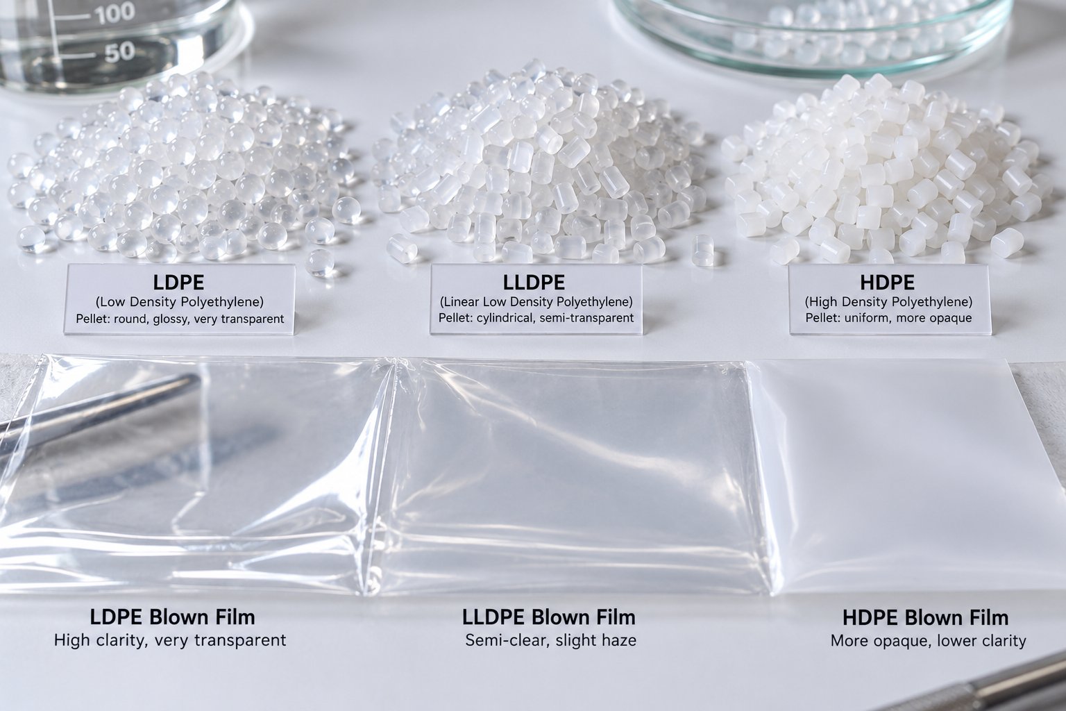
Material-Specific Defect Behavior Across Resin Families
Two blown film lines running identical equipment and identical process settings can produce completely different defects if one is extruding LDPE and the other LLDPE. That's not a fluke — it's polymer physics. Each polyethylene resin family carries a distinct molecular architecture that governs how it melts, flows through the die, stretches in the bubble, and crystallizes at the frost line. Ignoring these material-specific tendencies is one of the fastest routes to misdiagnosis, because the corrective action that solves a haze problem on LDPE may do nothing — or make things worse — on HDPE.
Understanding resin-specific defect behavior turns a generic troubleshooting approach into a precise one. Here's how the three major PE families differ.
LDPE Processing Characteristics and Common Defects
LDPE is the most forgiving resin in blown film extrusion. Its long-chain branched molecular structure produces strong strain-hardening behavior in elongational flow, which translates directly into excellent bubble stability. Multiple experimental studies on bubble instabilities have confirmed that LDPE consistently offers the widest stable operating window among commodity polyethylenes — meaning operators can adjust blow up ratio, take-up ratio, and frost line height across a broad range before encountering instability.
That generous processing window doesn't make LDPE defect-proof, though. The most common issues include:
- Haze at excessive melt temperatures — LDPE crystallization behavior is sensitive to cooling rate. When melt temperatures climb too high, the polymer takes longer to crystallize at the frost line, producing a cloudier film with reduced gloss. Keeping melt temperatures in the 160-180°C range typically preserves optical clarity.
- Melt fracture at high output rates — Even with its branched structure, LDPE can develop sharkskin when shear rates at the die land exceed the critical threshold. The onset tends to appear at higher output rates compared to linear resins, but once it starts, reducing output or widening the die gap is the fastest correction.
- Draw resonance under extreme conditions — While LDPE resists this instability far better than linear resins, pushing take-up ratios to extremes or running very low frost line heights can trigger periodic thickness pulsations.
LDPE's practical advantage is that most of its defects respond well to straightforward parameter adjustments. You rarely need to redesign the process — just dial it back within the resin's comfort zone.
LLDPE and mLLDPE Defect Tendencies
Switch from LDPE to LLDPE and you'll immediately notice a narrower processing window. LLDPE's linear molecular backbone — with short-chain branches but no long-chain branching — fundamentally changes its rheological behavior. The melt doesn't strain-harden the way LDPE does, which means bubble stability drops, extruder pressure rises, and the die becomes far more sensitive to shear rate.
The defect tendencies that follow are predictable once you understand this rheology:
- Melt fracture (sharkskin) — LLDPE hits its critical wall shear stress at lower output rates than LDPE, making surface roughness and sharkskin the most persistent quality complaint. Operators often need to run at reduced throughput, increase die gap, or add polymer processing aids (PPAs) to manage this defect.
- Higher extruder back pressure — The linear chains resist flow through the die more aggressively, driving up pressure. This limits maximum output and can trigger pressure alarms or extruder surging if the line is pushed too hard.
- Bubble instability — Draw resonance and helical instability are more common with LLDPE, particularly at elevated blow up ratios. Blending 15-25% LDPE into the formulation is a widely used industry strategy to restore bubble stability without sacrificing the mechanical advantages LLDPE provides.
Metallocene-catalyzed LLDPE (mLLDPE) amplifies every one of these tendencies. Research from the University of Salerno demonstrated that mLLDPE exhibits earlier onset and more severe melt fracture compared to conventional LLDPE with the same comonomer, a direct consequence of its narrower molecular weight distribution. The narrow MWD delivers outstanding dart impact and sealing performance — properties converters love — but it demands tighter process control and often lower line speeds to avoid surface defects.
If you've recently switched from conventional LLDPE to a metallocene grade and suddenly see sharkskin that wasn't there before, the resin's molecular architecture — not your equipment — is the first suspect.
HDPE Blown Film Challenges
HDPE blown film operates in a different world from its lower-density cousins. The high crystallinity and stiff molecular chains create a set of defect tendencies that catch operators off guard, especially those accustomed to running LDPE or LLDPE.
- Frost line sensitivity — HDPE crystallizes rapidly and the frost line position is extremely responsive to even minor changes in cooling air volume or temperature. Small fluctuations that LDPE would absorb without complaint can cause frost line height instability on HDPE, producing periodic gauge variation and layflat width changes.
- Neck instability at high blow up ratios — HDPE bubbles tend to develop a characteristic "wine glass" or high-stalk shape. Pushing the blow up ratio too high destabilizes the neck region between the die and the frost line, leading to helical instability or outright bubble collapse. Research on HDPE bimodal resins has shown that critical BUR thresholds exist beyond which the process becomes either unstable or entirely unreachable.
- Haze and brittleness from insufficient cooling — If the cooling rate is too slow, HDPE develops large crystalline structures (spherulites) that scatter light and increase haze. Simultaneously, the resulting crystalline morphology reduces impact strength and increases brittleness. Adequate cooling air velocity and properly designed dual-lip or IBC air rings are essential for maintaining both optical and mechanical quality.
The stability challenges in HDPE/LDPE film production also extend to blending scenarios. When LDPE regranulate is added to HDPE for economic or sustainability reasons, differences in melt flow properties between the two materials can introduce pressure fluctuations, surface roughness, and fisheyes — defects that neither resin would produce on its own.
Resin Family Processing and Defect Reference Table
The table below consolidates the key processing parameters and defect tendencies for each major polyethylene family. Use it as a quick-reference when switching resins or diagnosing defects that appeared after a material change.
| Resin Family | Typical Melt Temp Range | Recommended BUR Range | Most Common Defects | Key Processing Notes |
|---|---|---|---|---|
| LDPE | 160-180°C (320-356°F) | 1.5-4.0 | Haze at high melt temps; melt fracture at very high output; draw resonance at extreme TUR | Widest processing window; excellent bubble stability due to long-chain branching and strain-hardening behavior; reduce melt temp to improve optics |
| LLDPE (conventional) | 190-220°C (374-428°F) | 1.5-3.0 | Sharkskin / melt fracture; higher back pressure; bubble instability (draw resonance, helical); gauge variation | Narrower processing window than LDPE; consider PPA for melt fracture; blend 15-25% LDPE to improve bubble stability |
| mLLDPE (metallocene) | 190-215°C (374-419°F) | 1.5-2.8 | Early-onset sharkskin; severe melt fracture; sticky film (blocking); bubble instability | Narrow MWD intensifies melt fracture; superior dart impact and seal strength; often requires PPA and lower line speeds |
| HDPE | 190-230°C (374-446°F) | 2.0-4.0 (stalk dependent) | Frost line instability; neck / helical instability at high BUR; haze; brittleness from slow cooling | Rapid crystallization makes frost line very sensitive to cooling changes; often run with high-stalk bubble; requires strong, uniform cooling capacity |
One practical takeaway from this table: if a defect appears immediately after switching resin families — or even after changing lots within the same family — always compare the new material's melt flow index (MFI) and density against the previous lot. A shift of just 0.2 g/10 min in MFI or 0.002 g/cm³ in density can move your process out of its stable window, especially with LLDPE and HDPE grades where margins are already tight.
Resin behavior explains a great deal about why certain defects appear on certain lines. But many modern packaging films aren't single-layer at all — they're 3-, 5-, 7-, or even 9-layer coextruded structures where multiple resin families run simultaneously through a shared die. That complexity introduces an entirely different class of defects that generic blown film troubleshooting guides rarely address.
Multi-Layer Coextrusion Defects Most Guides Ignore
Walk into any modern flexible packaging plant and you'll find coextrusion lines producing 3-, 5-, 7-, and even 9-layer films as standard output. Each layer contributes a specific function — barrier, sealability, stiffness, printability, or adhesion — and the whole structure only works when every layer stays where it belongs, at the right thickness, bonded to its neighbors. Yet most blown film troubleshooting resources treat multi-layer production as an afterthought, if they mention it at all. That gap leaves operators diagnosing coextrusion-specific failures with monolayer logic, which almost never leads to the right answer.
Coextrusion defects are fundamentally different from single-layer problems. They arise at the interfaces between materials, inside the die where melt streams merge, and from the interaction between polymers with mismatched rheological properties. You can run a perfectly tuned extruder on every position and still produce defective film if the layers don't cooperate once they meet. Understanding where and why these failures occur is essential for any operation running multi-layer structures.
Delamination and Interfacial Adhesion Failures
Delamination — layers physically separating from each other — is the most immediately obvious coextrusion defect. You'll spot it as peeling edges on the wound roll, bubbling or blistering at layer interfaces during downstream converting, or catastrophically low peel-test results that should have been caught before the film shipped. When it's severe enough, delamination can cause the bubble itself to split apart at the interface, forcing an immediate line stop.
Three root causes account for nearly every delamination failure:
- Insufficient tie-layer thickness — Tie resins (typically maleic anhydride grafted polyolefins like Bynel or Plexar) need a minimum thickness to develop adequate bond strength. Research published in the Journal of Plastic Film and Sheeting demonstrated that interlayer peel strength in coextrusion is directly affected by fabrication parameters, including the thickness of adhesive layers. When tie-layer extruder output drops — even slightly — the adhesive film becomes too thin to bridge the incompatible polymers it's supposed to bond.
- Incompatible melt temperatures between layers — Each polymer in a coextruded structure has its own optimal processing temperature. When the temperature difference between adjacent layers at the point of confluence is too large, the interface forms under thermal stress. The hotter material may partially degrade the cooler one at the boundary, or the temperature mismatch may prevent adequate molecular interdiffusion between the tie resin and its substrate layers.
- Incorrect resin selection — Not all tie resins work with all polymer pairs. A tie layer designed for PE-to-nylon adhesion won't necessarily bond PE to EVOH effectively. Studies on EVOH-centered three-layer blown film structures found that even when using LLDPE-g-MAh as a compatibilizer, peel strength varied dramatically depending on EVOH concentration, blend composition, and the physical location of the compatibilizer within the structure. Choosing the wrong grade or placing it in the wrong layer position can result in a structure that looks intact but fails the first peel test.
Visual identification is straightforward once you know what to look for. Peeling layers at the roll edge, bubbles trapped between layers that weren't there during extrusion, and a "papery" feel when you flex the film all point to adhesion failure. A simple manual peel test — pulling layers apart by hand — can confirm delamination before lab instruments are even involved. If layers separate cleanly with little resistance, the bond never formed properly.
Layer Distribution and Encapsulation Problems
Imagine you've designed a five-layer barrier film with a precise layer ratio: 30% skin / 5% tie / 10% EVOH / 5% tie / 50% sealant. You've set each extruder's output to deliver exactly those percentages. But when you cross-section the finished film under a microscope, the EVOH barrier layer is shifted to one side and the skin layer has thinned dramatically — or worse, it's disappeared entirely in spots. What happened?
The answer is viscous encapsulation, one of the most insidious coextrusion defects. When adjacent layers have significantly different melt viscosities, the lower-viscosity material naturally migrates to the high-shear regions near the die walls, gradually encapsulating — wrapping around — the higher-viscosity material. This happens because the flow system seeks the path of minimum energy dissipation, and placing the less viscous polymer at the wall achieves exactly that. Research on interfacial flow instabilities in polymer coextrusion identifies viscous encapsulation as one of three fundamental instability types, alongside elastic layer rearrangement and interfacial wave or zigzag distortions.
The practical result is uneven layer distribution that no amount of extruder output adjustment can correct — because the problem isn't how much polymer you're feeding, it's how the polymers rearrange themselves inside the die after they merge. The only reliable fixes are reducing the viscosity mismatch (by adjusting melt temperatures or selecting resins with closer viscosity curves) or using die designs that minimize residence time after the confluence point.
Interlayer instability patterns represent a separate but related problem. Instead of one layer encapsulating another, the interface between layers develops wave-like or zigzag distortions that show up clearly in cross-section micrographs. Low-frequency wave-type instabilities produce broad, rolling undulations at the interface. High-frequency zigzag instabilities create sharp, sawtooth-like distortions that indicate severe process instability. Both types degrade the film's optical quality, create mechanical weak spots at the interface, and become dramatically worse if the film undergoes any downstream stretching such as orientation or thermoforming.
These interfacial instabilities are strongly dependent on the processing conditions and rheological properties of the specific material combination. Researchers have proposed that a critical interfacial shear stress level triggers the onset of distortions, and that matching the elastic properties of adjacent melt layers can help suppress them. In practice, this means that two resins which coextrude beautifully at one throughput and temperature may produce severe zigzag defects at a higher line speed or different temperature profile.
Diagnostic Steps for Multi-Layer Defect Investigation
Coextrusion defects can't be diagnosed the same way you'd approach a single-layer problem, because multiple extruders, a shared die, and several polymer streams all contribute simultaneously. A structured diagnostic sequence is essential:
- Check each extruder's output independently. Verify that every extruder is delivering its target throughput by running each one solo and measuring output gravimetrically. A 10% drop in tie-layer extruder output may not trigger a pressure alarm, but it can halve your peel strength.
- Verify melt temperatures per layer at the die inlet. Use melt temperature probes — not barrel zone setpoints — to confirm actual polymer temperatures. A 15°C mismatch between adjacent layers at the confluence can cause both adhesion failures and interfacial instabilities.
- Compare viscosity curves of adjacent layers at processing conditions. If you don't have rheology data, use the melt flow index (MFI) as a rough proxy. Adjacent layers with MFI ratios exceeding 3:1 are prime candidates for encapsulation problems.
- Inspect cross-sections under magnification. Microtome a sample and examine it with a polarized light microscope. You'll immediately see whether layers are at their target thicknesses, whether interfaces are clean, and whether wave or zigzag distortions are present.
- Evaluate die geometry and flow distribution. In feedblock-style dies, all materials must have similar melt temperatures and viscosities for balanced distribution. Multi-manifold dies tolerate larger differences but at higher cost and complexity. Confirm that the die type matches the material combination you're running.
- Review screw design per layer material. This is a hidden cause of layer-ratio problems that many operators overlook. Barrier screws are essential for processing EVOH, which has a sharp melting point and poor thermal conductivity. General-purpose three-zone screws work well for PE layers. Running EVOH on a standard PE screw produces erratic output, poor melt quality, and inconsistent layer thickness — problems that look like die issues but actually originate at the screw.
- Run a peel test at multiple points across the web width. Adhesion that varies from edge to center indicates non-uniform tie-layer distribution, which points back to die flow balance or encapsulation.
One often-overlooked factor in this diagnostic process is the mismatch between screw geometry and resin rheology. A coextrusion line with five extruders needs five properly specified screws — each one matched to the specific polymer it processes. A barrier screw designed for EVOH has a different compression ratio, channel depth, and barrier flight geometry than a metering screw designed for LDPE. When processors repurpose extruders between materials without changing the screw, they introduce output instability in individual layers that manifests as thickness variation, adhesion failures, or interfacial defects in the finished multi-layer film.
Coextrusion defects reward patience and methodical investigation. Unlike single-layer problems where one parameter change often resolves the issue, multi-layer failures typically involve the interaction of two or more variables — resin compatibility, temperature balance, viscosity matching, and die flow geometry — all influencing each other simultaneously. Rushing to adjust one variable without understanding the full picture usually shifts the problem rather than solving it.
Diagnosing any defect — single-layer or multi-layer — ultimately depends on the quality of your root cause analysis. And that analysis only works when it follows a repeatable, elimination-based method rather than relying on intuition or habit. The difference between a fast fix and a shift-long chase often comes down to how systematically you narrow the possibilities.
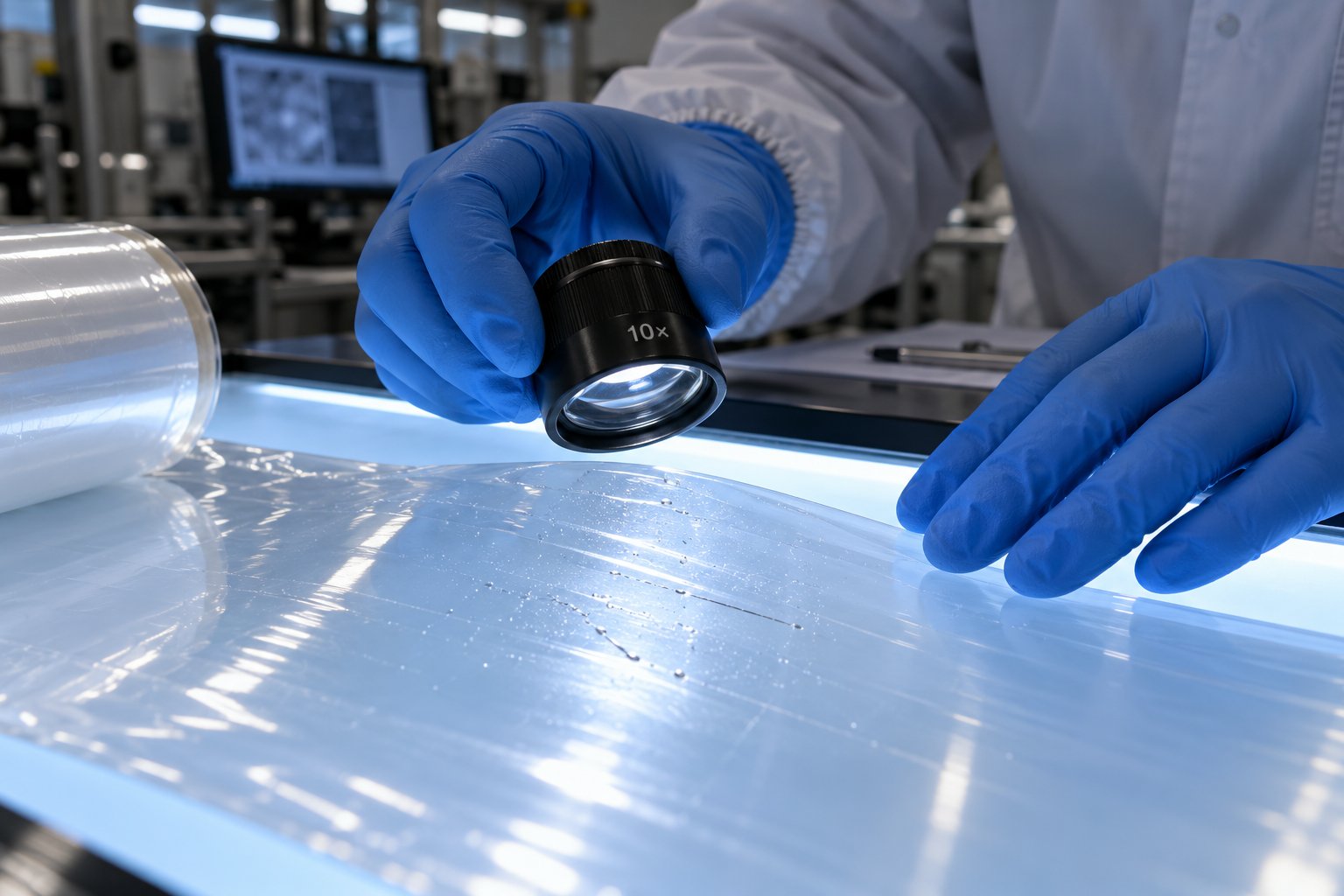
Systematic Root Cause Analysis That Finds Problems Faster
Picture this: a shift supervisor spots small raised specks scattered across the film web. Within minutes, one operator adjusts the melt temperature, another increases the screen pack mesh count, and a third calls the resin supplier to complain about the latest lot. Three actions, three assumptions, zero confirmed root cause — and the defect is still there two hours later. Sound familiar? This scenario plays out on blown film lines everywhere, not because the operators lack skill, but because they lack a repeatable diagnostic method that forces them to eliminate possibilities before committing to a fix.
The fastest path from defect to solution isn't a shortcut — it's a structured sequence. Root cause analysis tools like the 5 Whys and fishbone diagrams have long been used in laboratory and manufacturing quality systems, but they're equally powerful on an extrusion floor when adapted for the specific realities of blown film production. The key adaptation? Every blown film defect funnels into one of three root cause categories before any deeper investigation begins.
The Three-Category Triage for Every Defect
Before you touch a dial, change a setpoint, or call a supplier, answer one question: which category does this defect belong to? Every blown film quality problem traces back to one of three origins — and correctly categorizing it at the start prevents you from chasing solutions in the wrong direction for hours.
- Resin-related — The defect is caused by something in the raw material: a lot-to-lot property shift, contamination introduced through the material handling system, moisture absorption in hygroscopic layers, additive incompatibility, or degraded regrind blended into the feedstock.
- Equipment-related — The defect results from physical wear, damage, or calibration drift in the machinery itself: screw and barrel wear increasing clearance, die lip nicks, air ring blockage, thermocouple failure, or nip roll surface degradation.
- Process-parameter-related — The defect stems from an incorrect or drifted operating setting: melt temperature profile, line speed, blow up ratio, air ring velocity, winding tension, or screen pack configuration.
These three categories aren't just organizational labels — they drive the entire diagnostic elimination sequence. A resin-driven defect won't respond to a temperature change. An equipment-wear problem won't vanish with a new resin lot. And a parameter error won't fix itself through mechanical maintenance. Misclassifying the category wastes time in direct proportion to how far off-target your first guess lands.
Here's a practical elimination sequence you can apply every time a new defect appears:
- Did the defect start with a new resin lot, material change, or regrind addition? If yes, investigate resin first. Pull a sample of the new lot and compare its melt flow index and density against the previous lot. Check moisture content if hygroscopic materials are involved. Run the line on virgin resin without regrind to see if the defect disappears.
- Has the defect worsened gradually over days or weeks? If yes, investigate equipment wear. Gradual degradation — slowly increasing back pressure, declining output at the same RPM, die lines that worsen over time — almost always points to mechanical wear rather than a sudden resin or parameter issue. Measure screw-to-barrel clearance, inspect die lips under magnification, and check air ring components for buildup or damage.
- Did the defect appear immediately after a process adjustment? If yes, investigate parameters. Roll back the change, confirm whether the defect disappears, then re-introduce the adjustment in smaller increments to identify the threshold where the problem begins.
This sequence works because it mirrors the way defects actually enter a production run. Material changes are event-driven — they happen at a specific, identifiable moment. Equipment wear is time-driven — it creeps in over extended production periods. Parameter errors are action-driven — they correlate directly with a deliberate adjustment someone made. Matching the defect's onset pattern to the right category narrows your investigation dramatically before you even stand up from the operator console.
Think of it the same way fault tree analysis works in quality systems: you define the top-level failure event, then construct layers of possible causes beneath it, evaluating each branch until you isolate the one that leads to the actual root. The fault tree approach reminds us that there may be both primary and secondary causes stemming from a single branch — and that all should be evaluated before committing to a corrective action. On a blown film line, that discipline prevents the all-too-common mistake of treating a symptom while the real root cause continues operating beneath the surface.
Differentiating Similar-Looking Defects
The triage framework above only works if you can accurately identify what you're looking at in the first place. And here's where even experienced operators get tripped up: some of the most common blown film defects look nearly identical on a fast-moving web but have completely different root causes and demand completely different corrective actions.
Gels, fisheyes, and contamination specks are the classic trio of look-alike defects. All three appear as small raised imperfections in the film. All three catch your eye at roughly the same size range. And all three will lead you down a dead-end troubleshooting path if you confuse one for another. As blown film quality specialists note, gels alone can originate from multiple sources throughout the production line — degraded resin, unmelted material, contamination, or equipment buildup — making it critical to differentiate them from other defect types before choosing a corrective strategy.
Here's how to tell them apart:
Gels are crosslinked polymer particles — small regions where the polyethylene chains have chemically bonded into a three-dimensional network that can no longer melt or flow. They form when resin is exposed to excessive heat for prolonged periods, typically inside stagnant zones of the extruder, adapter, or die. Gels are hard, translucent, and embedded within the film matrix. You'll notice they're smooth to the touch because they've flowed through the die with the surrounding melt — they just didn't melt themselves. Their frequency pattern is persistent and steady: once a gel source establishes itself inside the equipment, gels keep appearing until that source is physically cleaned out or purged away.
Fisheyes are unmelt particles or poorly dispersed additive agglomerates. Unlike gels, fisheyes haven't crosslinked — they simply didn't receive enough thermal or mechanical energy to fully incorporate into the melt. You can often feel a slightly rougher texture when you run your finger over a fisheye because the unmelt core distorts the surrounding film. Fisheyes tend to appear in clusters or bursts, especially after startup when the extruder hasn't reached full thermal equilibrium, or when processing resins with very high molecular weight tails that resist melting. The root cause is almost always insufficient plasticating energy — low barrel temperatures, worn screw compression sections, or a screw geometry that doesn't match the resin's melting characteristics.
Contamination specks are foreign material — carbon particles, metal fragments, dust, fiber, or incompatible polymer from a previous production run. They're visually distinct if you know what to look for: contamination tends to appear as dark, opaque spots rather than the translucent or semi-clear appearance of gels and fisheyes. Foreign objects in the resin stream, angel hair from the material handling system, and residual material left in the screw or die after changeovers are the primary sources. The frequency pattern is the diagnostic giveaway — contamination often appears in bursts during or shortly after a material change, then tapers off as the old material clears the system. If it doesn't taper off, there's a persistent source such as equipment buildup breaking loose or an ongoing material handling problem.
The table below consolidates these differences into a quick-reference comparison you can use at the line:
| Characteristic | Gels | Fisheyes | Contamination |
|---|---|---|---|
| Visual Appearance | Small, translucent or clear raised spots embedded in the film; often circular with smooth edges | Semi-clear bumps with a visible unmelt core; may show a "halo" ring around a central particle | Dark, opaque specks; may appear black, brown, or as a different color than the base film |
| Touch / Feel | Smooth to the touch — blends with the surrounding film surface because the crosslinked material flowed through the die | Slightly rough or raised; the unmelt core creates a tactile bump that feels harder than the surrounding film | Can feel gritty or sharp depending on particle type; metallic contamination may scratch the surface |
| Frequency Pattern | Persistent and steady; continues at a consistent rate until the gel source inside the equipment is removed | Intermittent clusters, especially during startup or after resin changes; frequency may decrease as the extruder reaches thermal equilibrium | Burst pattern during or after material changeovers; tapers off as residual material clears unless a persistent source exists |
| Most Likely Root Cause | Degraded, crosslinked polymer from stagnant zones in the extruder, adapter, screen changer, or die; excessive residence time at high temperature | Insufficient melting energy — low barrel temps, worn screw compression zone, or screw geometry mismatched to resin; high-MW resin fractions resisting plasticization | Foreign material from handling system (dust, fiber, angel hair); carbonized residue from prior runs; incompatible polymer from incomplete purging |
| Corrective Action | Purge the system thoroughly; disassemble and clean dead spots in the adapter, screen changer, and die; establish preventive purging schedules; reduce residence time by optimizing throughput | Increase barrel temperatures in the compression and metering zones; verify screw wear and compression ratio; confirm resin MFI is within spec; extend heat soak time during startup | Clean and purge the material handling system, hopper, and dryer; purge the extruder with neat base resin; inspect screen pack for holes; improve material storage and handling protocols |
Notice how each defect points to a completely different area of the line and a completely different corrective action. Purging — while often the first instinct — only directly addresses gels and contamination. If your problem is fisheyes caused by a worn screw that can no longer generate enough compression, all the purging in the world won't eliminate them. You'll just keep purging and keep seeing the same defect, burning through purge compound and production time.
The diagnostic philosophy at work here mirrors what quality engineers call backward tracing: start with the defect as you observe it on the finished roll, then mentally walk it backward through each process stage — winder, nip, collapsing frame, frost line, air ring, die, adapter, screen changer, barrel, screw, feed throat, hopper — until you reach the stage where the defect was introduced. At each stage, ask: could this zone have created what I'm seeing? If the answer is no, move upstream. If the answer is yes, investigate that zone in detail before going further. This backward elimination method prevents you from jumping to conclusions and ensures you reach the true origin point rather than stopping at the first plausible explanation.
Applied consistently, this combination of three-category triage and backward-tracing elimination converts troubleshooting from a guessing game into a repeatable process. The operators who master it don't just fix problems faster — they fix the right problem the first time, which means fewer repeat failures, less wasted material, and more productive hours on every shift.
Still, even the best diagnostic method deals with problems after they've already appeared on the film. A defect that reaches the finished roll has already consumed resin, energy, and machine time. The real leverage — the shift that separates reactive troubleshooting from genuine process control — lies in understanding the conditions that create defects in the first place, including the environmental variables and startup practices that most operators overlook entirely.
Environmental Factors and Downstream Converting Impact
Ever notice how a blown film line that ran perfectly in October starts producing gauge variation and bubble instability in January — without a single setting change? Or how the first three rolls off a Monday morning cold start always end up as scrap? These aren't random glitches. They're environmental and startup-related defects — two categories that rarely appear in troubleshooting guides yet account for a surprising share of quality complaints on production floors worldwide.
Understanding these hidden triggers is what separates operators who constantly chase problems from those who anticipate them before the first meter of film hits the winder.
Seasonal and Environmental Factors That Cause Defects
Your extrusion line doesn't operate in a vacuum. It operates inside a building where ambient conditions change with the seasons — and those changes directly affect film quality in ways that process setpoints alone can't account for.
Ambient temperature swings are the most impactful variable. In summer, when plant floor temperatures climb to 35°C (95°F) or higher, the cooling air feeding your air ring arrives warmer. That shifts the frost line upward, extends the melt zone between the die and the solidification point, and changes the crystallization conditions that determine both optical clarity and mechanical strength. In winter, the opposite happens: colder ambient air supercools the bubble faster, dropping the frost line lower and potentially creating a narrower, less stable bubble geometry. Temperature fluctuations directly alter melt fluidity and viscosity, which means a process that was perfectly dialed in during spring may drift out of its stable window by midsummer without anyone touching a control.
Practical seasonal adjustments include:
- Summer: Increase cooling air volume or lower chiller setpoints to compensate for warmer inlet air. Monitor frost line height more frequently and expect to reduce line speed slightly on the hottest days.
- Winter: Reduce air volume or raise chiller temperature to avoid over-cooling the bubble. Watch for frost line instability caused by cold drafts from loading dock doors or poorly insulated plant walls.
- Year-round: Track ambient plant temperature at the start of every shift and log it alongside process data so seasonal trends become visible over time.
Humidity introduces a different set of problems, especially on coextrusion lines running hygroscopic resins like nylon (PA6 or PA6,6) as barrier layers. Nylon readily absorbs atmospheric moisture, and even a few hours of exposure to humid summer air can raise its moisture content above the critical threshold. When wet nylon enters the extruder, the moisture flash-vaporizes at processing temperatures, creating voids, raindrops, or gray streaks in the finished film. On hot, humid days, you may also see water condensation forming on the extruder feed section itself — a problem that introduces moisture into resins that aren't even hygroscopic. Checking moisture content with a heated moisture balance before loading the hopper, ensuring dryers are functioning properly, and sealing material handling systems against ambient humidity are non-negotiable practices during high-humidity months.
Startup and Shutdown Defect Patterns
Cold starts are a defect factory. Every blown film operator knows the first rolls off a shutdown line are rarely saleable — but understanding exactly why helps you minimize how many rolls end up as scrap.
The primary startup defect sources are:
- Thermal disequilibrium in the die — Even after barrel zones reach setpoint, the die body takes significantly longer to achieve uniform temperature throughout its mass. Until the die reaches full thermal equilibrium, localized cool spots alter melt viscosity at those locations, producing gauge bands and poor optical clarity that gradually improve as the die soaks.
- Degraded purge material — Polymer left in the barrel and die during shutdown degrades over time, especially at elevated temperatures. On restart, this degraded material flushes out as gels, discolored streaks, and carbon specks that contaminate the first several rolls. Thorough purging before shutdown — and again during startup — reduces but doesn't eliminate this issue entirely.
- Gauge instability during ramp-up — As extruder RPM, line speed, and cooling air volume ramp toward production setpoints, the process passes through transient conditions where output, bubble pressure, and frost line height are all shifting simultaneously. Gauge control systems can't fully compensate during these transitions, so early rolls typically show wider thickness variation than steady-state production.
Reducing startup scrap doesn't require expensive automation — it requires discipline. Allow adequate heat soak time before initiating extrusion (a minimum of 20-30 minutes after all zones reach setpoint is a common industry practice for medium-sized dies). Purge with a dedicated purging compound rather than relying on production resin alone. And resist the temptation to ramp to full speed too quickly — stepping up line speed in controlled increments gives the process time to stabilize at each stage.
How Film Defects Ruin Downstream Converting
Here's a question most extrusion operators don't think about enough: what happens to a defect after the roll leaves your plant? The answer is that even minor blown film defects cascade into major converting failures — failures that generate customer complaints, rejected shipments, and strained business relationships. Reifenhauser's converting performance research illustrates this connection clearly: film flatness alone can impact printing speed by up to 30%, adhesive consumption in lamination by up to 30%, and raw material waste through edge trimming by up to 10%.
The defect-to-converting cascade works like this: a problem that seems minor on the extrusion line amplifies at every downstream step because converting equipment operates at high speed with tight tolerances. What you might accept as "within spec" at the winder can become a line stoppage at the printer, laminator, or bag-making machine.
Common converting failures and their blown film defect origins:
- Printing registration errors — Caused by MD and TD gauge variation. Even +-5% thickness fluctuation alters web tension behavior at the print station, shifting color registration between print decks and producing misaligned graphics.
- Poor lamination bond strength — Caused by surface defects (orange peel, melt fracture, surface roughness) that reduce the effective contact area between the film and adhesive. A rough film surface traps air pockets at the adhesive interface, weakening the bond.
- Seal failures in bag-making machines — Caused by wrinkles, fold-overs, and gauge bands that create uneven contact at the seal bar. Thin spots in gauge bands overheat and burn through, while thick spots don't reach sealing temperature, producing intermittent leakers.
- Web breaks during slitting and rewinding — Caused by fisheyes, gels, or localized thin spots that act as stress concentrators under tension. A single gel in the wrong location can initiate a tear that propagates across the web at slitting speed.
- Curling and camber during lamination — Caused by uneven MD/TD orientation from unstable bubble conditions. Asymmetric molecular orientation creates internal stresses that cause the film to curl after lamination, making pouches or stand-up bags that won't lie flat.
- Inconsistent corona treatment uptake — Caused by surface contamination, bloom from over-concentrated slip additives, or gauge variation that alters the air gap at the corona treater electrode. Untreated spots lead to ink adhesion failures during printing.
This converting-impact perspective changes how you think about film quality tolerances. A gauge band that measures "within spec" by your plant's standards might still cause registration failures on a high-speed flexographic press running eight colors. Understanding the downstream consequences helps operators set meaningful internal quality targets — not just pass/fail limits, but targets that ensure the film performs at every stage of its journey from your winder to the end consumer's hands.
Environmental awareness and converting-impact thinking both share a common theme: they extend defect prevention beyond the extrusion line itself. That broader view — anticipating problems before they reach the film and understanding consequences after the film leaves the plant — is exactly the mindset that separates reactive troubleshooting from a true defect prevention program built on maintenance, monitoring, and standardized procedures.
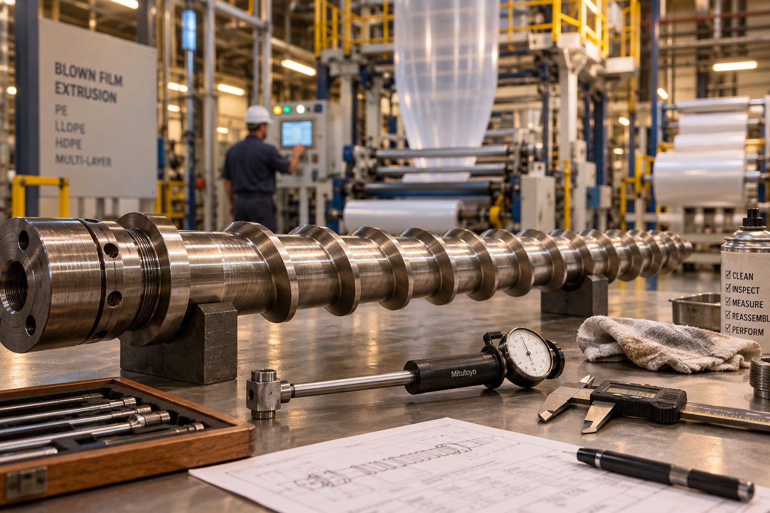
Building a Defect Prevention Program for Blown Film Troubleshooting
Fixing a defect after it appears on the film is necessary. Preventing it from ever appearing is profitable. That distinction — reactive versus proactive — defines the gap between plants that constantly firefight and plants that consistently ship quality rolls with minimal scrap. Every defect has a lifecycle: it originates silently, manifests visibly, gets diagnosed, receives a corrective action, and either recurs or gets permanently eliminated. Most blown film operations spend nearly all their energy on the middle stages — diagnosis and correction — while neglecting the bookend steps of root cause elimination and prevention that actually stop defects from coming back.
A genuine defect prevention program doesn't rely on heroic troubleshooting. It relies on structured maintenance, disciplined startup procedures, modern process monitoring, and rigorous material handling — the unglamorous daily habits that keep problems from forming in the first place.
Preventive Maintenance Schedules That Reduce Defects
Most blown film defects linked to equipment wear don't appear overnight. They creep in over weeks and months, worsening so gradually that operators normalize them — until quality falls off a cliff and a customer rejects an entire shipment. A tiered maintenance schedule catches these creeping failures early, long before they reach the finished film.
Here's a practical maintenance framework organized by interval. Adapt it to your specific line size and production intensity, but don't skip the intervals entirely — that's where plants get into trouble.
| Interval | Maintenance Task | Defects Prevented |
|---|---|---|
| Daily | Clean die lips with brass or copper tools; inspect for nicks and buildup. Verify all zone temperatures match setpoints. Check for unusual vibrations or noises. | Die lines, contamination streaks, localized gauge variation from lip damage |
| Weekly | Inspect air ring for debris, blocked holes, and uneven airflow. Lubricate moving components per manufacturer guidelines. Test sensor calibration on tension and edge-guide systems. Clean filters and air intakes. | Bubble sway, one-sided thickness variation, web tracking errors, frost line instability |
| Monthly | Pull the screw and measure flight OD at multiple points along its length. Measure barrel bore ID using a telescoping bore gauge or go/no-go gauges. Record back pressure trend at a standard RPM. Inspect screen changer seals and adapter surfaces for dead zones. | Output surging, melt temperature drift, gels from stagnant zones, gauge variation from worn compression sections |
| Quarterly | Fully strip and clean the die body and all flow channels. Inspect heater bands and thermocouples for drift or failure. Conduct thermal imaging across the barrel and die to detect hot spots. Review gearbox oil condition. | Degradation specks, heater-band hot spots, thermocouple-driven temperature errors, long-term thermal non-uniformity |
| Annually | Complete barrel alignment check. Full safety inspection of guards, interlocks, and emergency stops. Calibrate all load cells, tension controls, and automatic gauge measurement systems. Back up all machine settings and recipe data. | Accelerated screw/barrel wear from misalignment, safety incidents, measurement drift causing false quality readings |
The monthly screw and barrel measurement deserves special emphasis because it's the single most predictive maintenance action you can take. As Plastics Technology details, the flight clearance on a new screw is typically the nominal diameter divided by 1000 — roughly 0.004 inches per side on a 3.5-inch extruder. When that clearance doubles, molten polymer leaks backward over the flights, discharge temperature rises, and specific output drops. By the time clearance reaches four times the original value, the extruder may need to reduce throughput by 13% or more just to maintain acceptable melt temperature — a direct hit to profitability and capacity.
Tracking these measurements over time on a simple spreadsheet creates a wear curve that predicts — months in advance — when output instability and melt quality defects will cross from tolerable into problematic. You'll know exactly when a screw refurbishment or barrel replacement needs to happen, and you can schedule it during a planned shutdown instead of reacting to a quality crisis mid-run. A screw should generally not be refurbished more than three times, as repeated hard-facing welding deteriorates the base metal and increases delamination risk. Keeping a spare screw in storage ensures you can swap quickly without extending downtime.
Barrel wear follows a similar logic. An iron-based bimetallic barrel liner typically lasts about three times the service life of a screw, but it still needs periodic bore measurement to confirm. When bore measurements show the liner approaching end-of-life, proactive replacement restores the tight tolerances essential for consistent melt quality. NANHAIYA offers custom and replacement single screw barrels engineered for film extrusion applications, giving processors a practical path to maintain precision clearances and prevent the cascade of wear-related defects — surging, gauge variation, elevated discharge temperatures — that erode film quality long before they trigger an alarm.
Startup Procedures and Process Monitoring Best Practices
Startup scrap is one of the most accepted — and most preventable — sources of waste on a blown film line. Every cold start produces a window of transient conditions where gauge control, optical quality, and mechanical properties are all subpar. You can't eliminate that window entirely, but a disciplined startup procedure shrinks it dramatically.
The startup sequence below is adapted from Davis-Standard's recommended restart methodology for blown film lines and reflects widely accepted industry practice. Adjust temperatures and soak times based on your specific equipment size, resin type, and die mass — but respect the underlying principle: bring the system to temperature gradually, soak thoroughly, and confirm full melt before turning the screw.
- Set the die to an initial low temperature (approximately 120°C / 250°F for PE applications) and soak for at least one hour. The die's thermal mass is the bottleneck — it takes far longer than barrel zones to reach uniform temperature throughout.
- Step up the die temperature in 25°C increments, soaking 15 minutes at each stage. Simultaneously bring adapters and screen changers online at progressively rising setpoints.
- Turn on extruder barrel zones last, starting at a temperature below normal operating range (approximately 150°C / 300°F for PE). This minimizes thermal degradation of stagnant polymer left from the previous run.
- Set barrel zones to the production startup profile and heat soak for a minimum of 15 minutes after all zones reach setpoint. For larger extruders (above 90 mm), extend this soak — the center of the polymer mass inside the barrel lags behind the thermocouple reading at the wall.
- Idle the extruder at low RPM (~10 RPM) and monitor head pressure. Push out the shutdown purge material until the extrudate runs clear — the dark brown color from antioxidant-loaded shutdown resin should clear relatively quickly if the shutdown procedure was done properly.
- Change the screen pack to production mesh once the material runs clear. This removes any degraded particles trapped during the purge phase.
- Clean and re-gap the die lips as needed. If a bead of material was left on the die lip during shutdown (recommended practice), this step is minimal.
- Set production temperature profiles and string the bubble. Ramp line speed in controlled increments — typically 25% steps — allowing gauge control and bubble stability to settle at each stage before increasing further.
- Divert the first rolls as off-grade until automatic gauge control confirms thickness variation is within production tolerances. Don't assume the film is saleable just because the bubble looks stable.
Two modern monitoring tools dramatically reduce defect rates during both startup and steady-state production. Automatic gauge control (AGC) systems continuously measure film thickness around the bubble circumference and adjust die bolt heaters in real time to correct gauge variation — a level of precision no human operator can match manually. Gravimetric dosing systems weigh raw material in real time and adjust feeder speed to maintain exact output, eliminating the throughput fluctuations that cause MD gauge variation. Plants that invest in these systems consistently report measurable reductions in off-grade production and faster transitions between recipes.
Material Handling: The Overlooked Defect Source
You can maintain your equipment flawlessly and follow a perfect startup checklist, yet still produce defective film if the resin reaching the hopper is compromised. Material handling defects — moisture contamination, degraded regrind, cross-contamination between resins, and thermally aged pellets — are among the most frustrating because they mimic equipment and process problems, sending operators on wild-goose chases through the wrong diagnostic branches.
Three material handling practices eliminate the majority of these issues:
- Proper drying of hygroscopic resins — Nylon, EVOH, and certain specialty polymers absorb atmospheric moisture rapidly. Desiccant dryers must maintain dewpoint below -40°C, and dried material should be consumed within a defined time window (typically 4-6 hours) before moisture re-absorption becomes problematic. On humid summer days, that window shrinks further — monitor it actively rather than relying on a fixed schedule.
- Sealed storage and conveying — Open bins, uncovered gaylords, and pneumatic conveying lines with leaking joints all introduce moisture and airborne contamination. Sealed hoppers with desiccant breathers, covered storage containers, and properly maintained conveying systems are basic requirements, not luxuries.
- FIFO (first in, first out) rotation — Resin that sits in a warehouse for months undergoes slow thermal and oxidative degradation, especially if stored near heat sources or in direct sunlight. Implementing strict FIFO rotation ensures the oldest material gets consumed first, preventing the accumulation of degraded stock that shows up as gels, discoloration, and reduced mechanical properties once it finally reaches the extruder.
Think of material handling as the foundation beneath your entire defect prevention program. Contaminated or degraded resin undermines every other investment you've made — in maintenance, in monitoring, in operator training. Keep the feedstock clean, dry, and fresh, and you eliminate an entire category of defects before the first pellet enters the feed throat.
Prevention transforms the economics of quality. Every defect you stop from forming is a defect you never need to diagnose, never need to troubleshoot, and never need to explain to a customer. But even the best prevention program can't eliminate every issue — so having a clear, prioritized response protocol for the defects that do slip through is the final piece of a complete blown film quality system.
Prioritized Corrective Actions and Next Steps
A defect just appeared on your web. You've classified it, traced it to a process zone, and identified the most likely root cause. The final question — the one that determines whether you protect the next hundred rolls or sacrifice them — is simple: how urgently do I need to act? Not every defect demands the same response speed. Treating a gradual die line worsening with the same panic as a bubble burst wastes resources and disrupts production unnecessarily. Conversely, ignoring a severe melt fracture because "it might clear up" turns a correctable problem into pallets of unsalvageable scrap.
A tiered response protocol removes the guesswork. It tells every operator on every shift exactly what action a given defect severity level requires — immediately, within the current run, or at the next scheduled maintenance window.
Defect Severity Ranking and Response Protocols
The table below assigns every major blown film defect to one of three urgency tiers. Post it near the operator console so the decision framework is accessible the moment a problem surfaces — no flipping through manuals, no debating with colleagues, no costly hesitation.
| Urgency Tier | Response Action | Defect Examples | Why This Tier |
|---|---|---|---|
| Tier 1 — Immediate Line Stop | Stop the extruder, secure the bubble, and diagnose before restarting. Do not attempt to "run through" the problem. | Bubble burst or tear; severe melt fracture compromising film integrity; extruder surge with pressure alarm; complete delamination causing bubble failure; foreign object contamination indicating equipment damage | These defects produce 100% scrap while active and may indicate equipment damage that worsens with continued operation. Every minute of delay multiplies waste. |
| Tier 2 — Adjust While Running | Make targeted, incremental corrections without stopping the line. Monitor closely and escalate to Tier 1 if the defect worsens. | Minor gauge drift (MD or TD); slight haze increase; frost line height shift; mild bubble sway; light die lines; minor blocking tendency; small changes in layflat width | Film is still usable or borderline. Stopping the line creates more scrap than careful real-time adjustment. However, ignoring Tier 2 defects allows them to escalate into Tier 1 events. |
| Tier 3 — Scheduled Maintenance | Log the observation, track the trend, and schedule corrective maintenance during the next planned shutdown. | Gradual die line worsening over weeks; slow output decline at constant RPM; increasing back pressure trend; progressive dart impact reduction; slowly rising haze baseline; minor roll hardness inconsistency | These defects reflect wear or drift that isn't yet affecting saleable quality. Acting during a planned window avoids unplanned downtime while preventing eventual Tier 1 failures. |
Notice the escalation logic built into this framework. A Tier 3 defect that goes unaddressed — say, a back pressure trend climbing 50 PSI per month due to screw wear — eventually becomes a Tier 2 gauge variation problem, then a Tier 1 extruder surge that trips the pressure alarm and forces an emergency stop. The entire point of tiered response is to catch problems at Tier 3 and resolve them on your schedule, not the machine's.
Operators sometimes ask: "What if a defect falls between tiers?" The answer is always to round up. A die line that seems borderline between Tier 2 and Tier 3 should be treated as Tier 2. A bubble instability that might be Tier 1 or Tier 2 should be treated as Tier 1. Conservative triage costs minutes; optimistic triage can cost entire production runs.
Your Next Steps Toward Consistent Film Quality
Everything covered across this guide — from defect taxonomy to process-zone mapping, resin-specific behavior, multi-layer diagnostics, systematic root cause analysis, environmental factors, and preventive maintenance — converges on a single operating philosophy. The best blown film operations don't rely on a few expert troubleshooters who happen to be on shift when problems appear. They build systems that every operator can follow, every shift, regardless of experience level.
Here are the core principles worth carrying forward:
- Classify first, act second. Determine whether a defect is surface, dimensional, mechanical, or stability-related before adjusting any process setting. Misclassification leads to wasted effort and wasted film.
- Trace defects to their process zone. Walk to the right area of the line — feed section, die, air ring, collapsing frame, or winder — instead of guessing from the operator console. The zone tells you the fix.
- Account for resin-specific behavior. LDPE, LLDPE, mLLDPE, and HDPE each carry distinct defect tendencies. A solution that works for one resin family may worsen a defect on another.
- Use elimination-based diagnostics. Ask the three triage questions — new material? gradual worsening? recent adjustment? — to narrow the root cause category before investigating details.
- Invest in prevention over reaction. Daily die lip cleaning, monthly screw measurements, proper heat soak procedures, and disciplined material handling eliminate defects that would otherwise consume hours of troubleshooting time.
The best-run blown film lines do not produce fewer defects because they troubleshoot faster — they produce fewer defects because they prevent them systematically.
Your most powerful next step is also the simplest: create a line-specific reference card for your team. Combine the defect taxonomy table from Chapter 2, the zone-by-zone signature list from Chapter 3, and the tiered response protocol above into a single laminated document posted at the operator station. When every team member — from the newest hire to the most seasoned veteran — can glance at a shared reference and immediately classify, locate, and prioritize a defect, your entire operation moves from individual expertise to institutional capability. That shift is where consistent film quality truly lives, and it's what allows blown film extrusion machine manufacturers, converters, and end users alike to trust the rolls coming off your line, every shift, every season, every year.
Frequently Asked Questions About Blown Film Defects and Solutions
1. What are the most common blown film extrusion defects?
The most frequently encountered blown film defects fall into six families: surface and optical issues (die lines, gels, fisheyes, melt fracture, haze), dimensional problems (MD and TD gauge variation, thickness bands, uneven layflat), bubble stability failures (sway, draw resonance, helical instability), mechanical property shortfalls (poor dart impact, brittleness, weak seals), equipment-origin flaws (screw wear marks, contamination streaks, heater-band hot spots), and multi-layer-specific defects (delamination, encapsulation, interlayer distortion). Classifying a defect into the correct family is the essential first step before any corrective action, because each family points to a different origin zone on the extrusion line and demands a different fix.
2. How do you tell the difference between gels, fisheyes, and contamination in blown film?
All three look like small raised imperfections, but they have distinct characteristics. Gels are crosslinked polymer particles that appear translucent, feel smooth to the touch, and persist at a steady rate until the source inside the extruder or die is purged. Fisheyes are unmelt or poorly dispersed additive particles that feel slightly rougher, often show a visible core with a surrounding halo, and tend to appear in clusters during startup or resin transitions. Contamination specks are foreign material — carbon, metal, dust, or residual polymer — that look dark and opaque, and typically arrive in bursts after material changeovers. The corrective actions differ entirely: gels require purging and dead-zone cleaning, fisheyes call for increased barrel temperatures or screw compression improvements, and contamination demands material handling system cleaning and better purge protocols.
3. Why does LLDPE cause more melt fracture than LDPE in blown film extrusion?
LLDPE's linear molecular backbone lacks the long-chain branching present in LDPE. This structural difference means LLDPE doesn't exhibit the strong strain-hardening behavior that gives LDPE its wide processing window. Instead, LLDPE reaches its critical wall shear stress at lower output rates, causing sharkskin-type melt fracture to appear sooner and more severely. Metallocene LLDPE (mLLDPE) intensifies this tendency further due to its narrow molecular weight distribution. Practical solutions include reducing throughput, increasing the die gap, raising melt temperature slightly, blending 15-25% LDPE for bubble stability, or adding polymer processing aids (PPAs) to lubricate the die land surface.
4. How does screw and barrel wear affect blown film quality?
As the clearance between the screw flight and barrel wall increases through abrasive and corrosive wear, molten polymer leaks backward over the flights instead of moving forward. This causes output surging, inconsistent melt temperature, rising back pressure, and poor melt homogeneity — all of which manifest as gauge variation, surface defects, haze differences, and mechanical property drift at the die. A throughput drop of 15% or more at constant RPM is a strong indicator of significant wear. Monthly measurement of screw flight OD and barrel bore ID using go/no-go gauges creates a predictive wear curve. When replacement is needed, suppliers like NANHAIYA provide custom single screw barrels engineered for film extrusion to restore tight tolerances without extended downtime.
5. What preventive maintenance reduces blown film defects the most?
A tiered maintenance schedule delivers the greatest defect reduction. Daily die lip cleaning prevents die lines and contamination streaks. Weekly air ring inspection and airflow verification prevent bubble instability and one-sided gauge variation. Monthly screw pull and barrel bore measurement — the single most predictive action — catches wear before it degrades melt quality. Quarterly die disassembly with heater band and thermocouple inspection eliminates degradation specks and thermal non-uniformity. Beyond equipment maintenance, disciplined startup procedures with proper heat soak times, thorough purging, and controlled ramp-up speeds minimize startup scrap. Rigorous material handling — drying hygroscopic resins, sealed storage, and FIFO rotation — eliminates moisture and degradation defects that mimic equipment problems.
Written by
Nanhaiya Technical Team
Zhoushan Nanhaiya Plastic Machinery Co., Ltd.
The Nanhaiya technical team supports screw and barrel manufacturing projects through application review, technical communication, custom manufacturing coordination, and production and quality control.
Discuss Your Application
Related Articles
More insights on screw barrel technology and plastics processing.
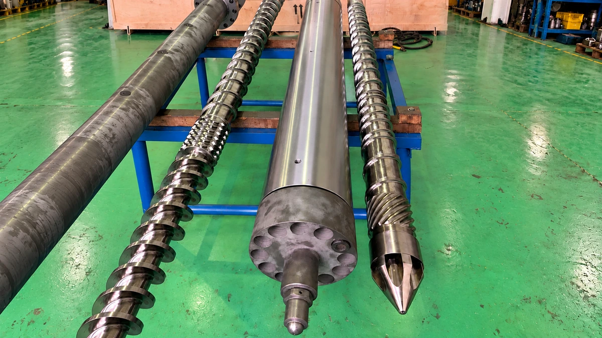
Screw Speed Injection Molding: The Parameter Most Molders Get Wrong
Nov 4, 2026
Learn how screw speed in injection molding controls melt quality, shear heating, and residence time. Avoid common RPM mistakes with this in-depth process guide.
Read Article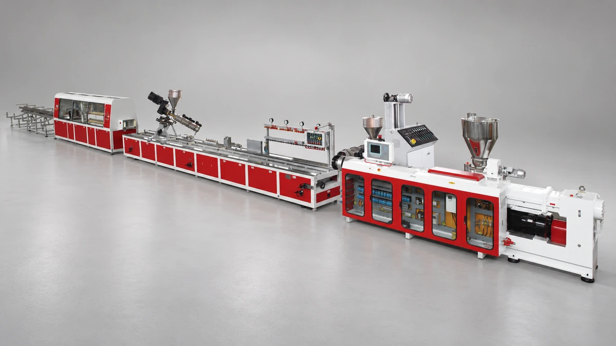
PVC Profile Extruder Stripped Down: Screws, Dies, and Defect Fixes
Nov 3, 2026
PVC profile extruder guide covering screw types, die design, temperature control, defect troubleshooting, and sizing advice for window frames, trunking, and trims.
Read Article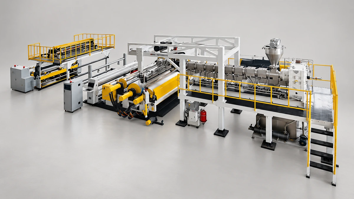
Plastic Sheet Extrusion Line Mistakes That Silently Kill Your Margins
Nov 3, 2026
Avoid costly plastic sheet extrusion line mistakes. Learn component specs, die design, polymer configs, screw selection, and troubleshooting to protect margins.
Read ArticleLooking for something else?
Search by material, symptom or product and jump straight to the relevant page.
These are navigation suggestions based on keyword matching — not a quotation, not a delivery commitment, and not a substitute for engineering review. Final specification is confirmed by our engineers against your drawings and processed material.
Need help with screw barrel selection?
Share your machine model, processed material and application. Our team can help with pricing and technical support.