

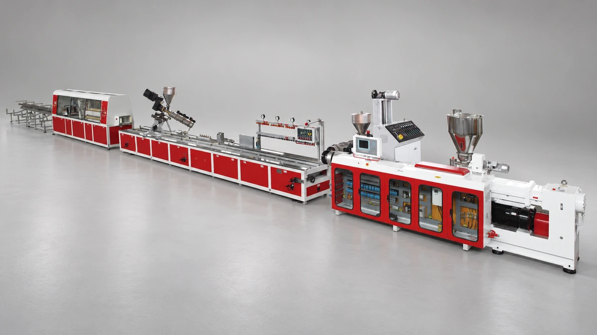
What a PVC Profile Extruder Does and Why It Matters
Imagine every uPVC window frame, cable trunking channel, and decorative trim piece you have ever seen. They all started as dry powder or pellets, and a single category of machine turned them into finished, continuous shapes. That machine is the PVC profile extruder — and understanding how it works is the first step toward better procurement decisions, smoother production runs, and fewer quality headaches.
What Is a PVC Profile Extruder
At its core, this equipment does one job extraordinarily well: it converts a rigid PVC compound into a precisely shaped, continuous length of plastic extrusion profile.
A PVC profile extruder is a thermoplastic processing machine that heats and melts a PVC compound inside a barrel-and-screw assembly, then forces the molten material through a custom-shaped die to produce continuous profiles with a consistent cross-section.
The process — known broadly as PVC extrusion — sounds straightforward, yet every stage demands tight control. The compound must reach its melt temperature without degrading. The die must distribute flow evenly across complex geometries. Downstream equipment must cool, size, pull, and cut the profile without distorting it. When every element synchronizes, the result is PVC extruded profiles that hold dimensional tolerances measured in fractions of a millimeter.
Why PVC Profile Extrusion Matters in Modern Manufacturing
Polyvinyl chloride ranks as the third most-produced plastic globally, trailing only polyethylene and polypropylene. A huge share of that volume flows through profile extrusion lines. Consider a few of the products that depend on this process daily:
- Window and door frames — multi-chamber uPVC profiles that deliver thermal insulation, weather resistance, and decades of service life.
- Cable trunking and conduit — rigid channels that protect electrical wiring in commercial and industrial buildings.
- Skirting boards and decorative trims — aesthetic finishing elements used across residential and hospitality interiors.
- Co-extruded plastic profiles — multi-material designs combining a rigid core with a flexible sealing lip for automotive or architectural applications.
For procurement teams, production managers, and R&D engineers, the extruder is not just another line item on a capital equipment list. It is the heart of the entire plastic extrusion profile operation — dictating output volume, energy costs, surface finish quality, and long-term maintenance budgets. Choosing the wrong machine specification, or neglecting a critical wear component, ripples through every meter of profile that rolls off the line.
This article goes deeper than the typical overview. In the sections ahead, you will find a full component-by-component anatomy of the machine, an honest comparison of single-screw and twin-screw designs, a practical defect-troubleshooting guide, and actionable advice on sizing and maintaining your extruder. The goal is to give you the technical grounding that product catalogs leave out — so the next specification sheet you read actually makes sense.
That depth starts with knowing exactly what sits inside the machine, from the feed hopper all the way to the flying saw at the end of the line.
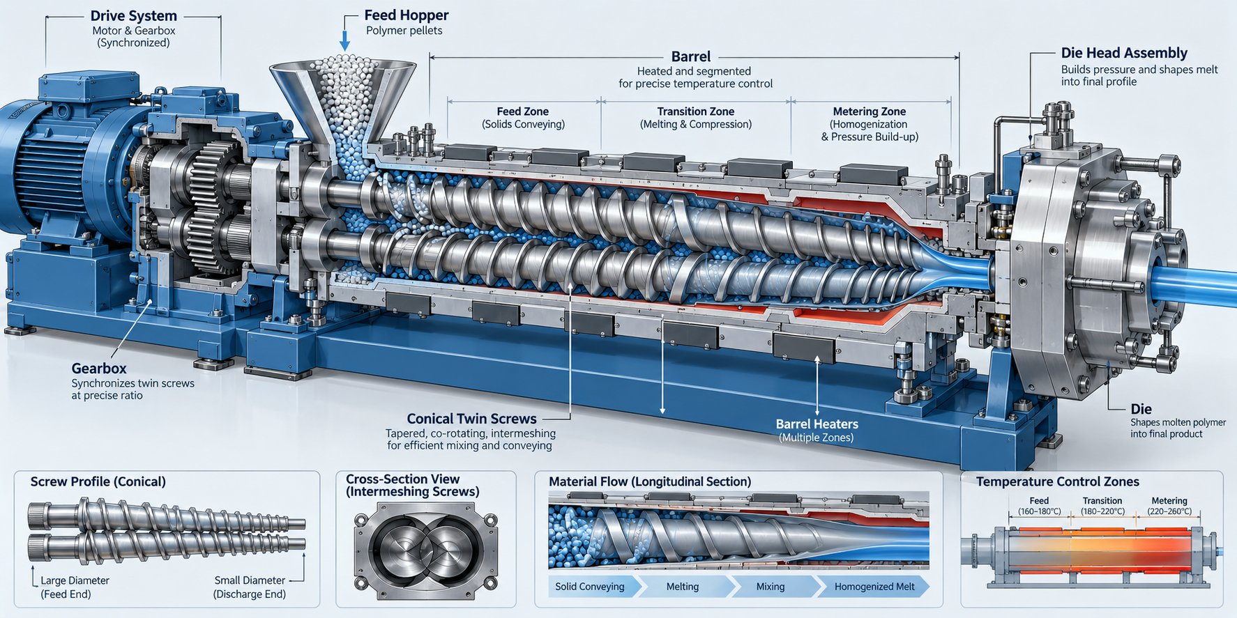
Anatomy of a PVC Profile Extruder from Hopper to Cutter
Picture a relay race where every runner must hit their mark at exactly the right moment. Drop the baton at any handoff and the whole team loses. A PVC profile extrusion line works the same way — raw compound enters one end, and a finished profile exits the other, but only if every component between those two points performs its role in tight synchronization. Let's walk through the machine station by station so you know precisely what each part does and why it matters.
Feed System and Barrel Assembly
Everything begins at the feed hopper, where pre-mixed PVC dry blend — resin plus stabilizers, lubricants, fillers, and pigments — enters the extruder. How that material is dosed into the barrel sets the tone for the entire run. Two feeding approaches dominate the industry:
- Volumetric feeding — delivers material based on a fixed screw or auger speed. It is simpler and less expensive but sensitive to changes in bulk density. If your dry blend's particle size shifts between batches, the actual mass flow rate will fluctuate.
- Gravimetric feeding — uses a loss-in-weight or weigh-belt system that continuously measures the mass being delivered and adjusts feed rate in real time. This approach keeps output more consistent, especially for formulations with variable filler loading or recycled content.
For high-tolerance PVC extrusion — think multi-chamber window profiles where wall thickness must stay within fractions of a millimeter — gravimetric dosing is the safer choice. Consistent feed rate translates directly into stable melt pressure and, ultimately, uniform profile dimensions.
Below the hopper sits the barrel, and this is where metallurgy starts to matter. During processing, PVC releases small amounts of hydrochloric acid (HCl) gas, which is highly corrosive. A standard carbon-steel barrel would pit and erode in a matter of months. That is why barrels designed for PVC profile extrusion feature specialized linings:
- Nitrided steel linings — a nitrogen-diffusion surface treatment that hardens the barrel bore and improves corrosion resistance at a moderate cost.
- Bimetallic linings — a centrifugally cast alloy sleeve (often nickel- or cobalt-based) bonded inside the barrel, offering superior resistance to both abrasive fillers like calcium carbonate and the corrosive HCl environment.
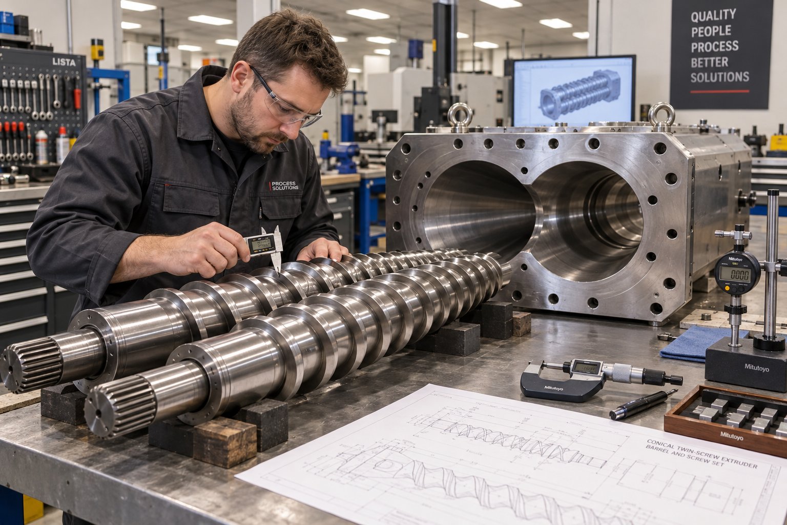
Housed inside the barrel is the screw system — the true engine of PVC extrusion. Screws convey, compress, and plasticize the dry blend into a homogeneous melt. Their geometry — flight depth, pitch, compression ratio, and the design of mixing or shearing elements — directly controls how much heat the material absorbs through friction and how uniformly it melts. Get the screw design wrong for a given formulation, and you'll face either under-plasticized compound (poor fusion, weak profiles) or excessive shear heat (degradation, discoloration, and that telltale burnt smell on the shop floor). In conical twin-screw designs, the screws taper from a larger diameter at the feed end to a smaller one at the metering end, providing high intake capacity and gentle, progressive compression — an arrangement particularly well suited to heat-sensitive PVC.
Die Head, Calibration Table, and Downstream Equipment
Once the compound is fully plasticized, it exits the barrel as a uniform melt stream and enters the die head. This is where the magic of shaping happens. The die transforms a round melt flow into the final profile cross-section — whether that's a simple rectangular cable trunking channel or a complex multi-chamber window frame with internal ribs and hollow sections. Flow channels inside the die must be carefully balanced so that melt velocity is even across the entire exit. Any imbalance shows up immediately as uneven wall thickness or warped geometry in the finished product.
From the die, the hot, soft extrudate passes through a sequence of downstream stations. Each one has a specific job, and they all have to run in lockstep with each other and with the extruder itself. Here is a quick-reference breakdown of every major downstream component in a typical plastic profile extrusion line:
- Vacuum calibration table — applies vacuum suction through a shaped calibrator sleeve to pull the hot profile against precision-machined walls, locking in the exact cross-sectional dimensions while water cooling solidifies the outer skin.
- Spray or immersion cooling tanks — continue cooling the profile after calibration, removing residual heat from the core so the part is dimensionally stable before it reaches the haul-off.
- Haul-off unit — grips the cooled profile with rubber-padded belts or caterpillar tracks and pulls it through the entire downstream line at a precisely controlled speed. The pulling speed must match the extruder's output rate; too fast stretches the profile thin, too slow creates back-pressure surges.
- Cutting unit — slices the continuous profile into finished lengths. A flying saw travels with the profile during the cut so the line never stops, while a guillotine cutter is simpler and suited to lower line speeds or softer compounds.
- Stacking or tilting table — collects and organizes cut lengths for inspection, bundling, or palletizing at the end of the line.
Every one of these stations communicates — either through a central PLC or through closed-loop speed synchronization. If the haul-off accelerates by even a small percentage without a corresponding extruder speed adjustment, the profile's weight per meter drops and wall thicknesses drift out of tolerance. If the vacuum calibration pump loses suction, the profile swells beyond its target dimensions before the cooling tanks can freeze the shape in place.
This is the fundamental engineering reality of PVC extrusion: no single component works in isolation. The extruder delivers a melt stream whose pressure, temperature, and homogeneity determine what the die can produce. The die's flow balance determines what the calibration system must correct. And the haul-off speed ties everything together into a stable, continuous process. When procurement teams or production engineers evaluate a new line, understanding how these stations interact is far more valuable than fixating on any one specification in isolation.
Yet the machine alone tells only half the story. The material flowing through it — rigid PVC compound — brings its own set of challenges that no other common thermoplastic shares, and those challenges shape every design choice you have just read about.
Why PVC Demands Specialized Extruder Engineering
Every thermoplastic has quirks, but PVC sits in a category of its own. Its molecular structure creates processing constraints that directly dictate how every component of the extruder — screws, barrel, heaters, die — must be designed. Ignore the chemistry, and you'll wonder why your profile extrusion line keeps producing discolored parts, rough surfaces, or brittle profiles. Respect it, and the machine becomes remarkably capable of turning out extruded PVC profiles with tight tolerances and clean finishes, batch after batch.
PVC's Thermal Sensitivity and Narrow Processing Window
Here is the core problem: PVC starts to decompose at temperatures dangerously close to the temperatures required to plasticize it. Polyethylene and polypropylene offer generous thermal headroom — you can overshoot their ideal melt temperature by tens of degrees before anything goes wrong. PVC offers no such cushion.
When PVC overheats, its polymer chains undergo dehydrochlorination — stripping hydrogen chloride (HCl) gas right out of the molecular backbone. This reaction is not subtle. HCl is corrosive enough to attack barrel and screw surfaces, and the degraded polymer turns dark, brittle, and structurally useless. Thermogravimetric studies show that the primary degradation stage for PVC kicks in around 540-620 K, which overlaps uncomfortably with the range needed to achieve full gelation of a rigid compound.
What does this mean in practical terms? The extruder's temperature control system must deliver heat that is both precise and uniform. A single hot spot along the barrel — caused by a failing heater band, a miscalibrated thermocouple, or even poor screw geometry that creates excessive localized friction — can push the compound past its degradation threshold while the rest of the melt is still under-fused. That is why PVC profile extruders demand more independently controlled heating zones, tighter PID tuning, and more sophisticated screw designs than machines built for polyolefins. The margin for error simply is not there.
How Shear Control and Compound Formulation Affect Extruder Choice
Temperature is only half the equation. Shear — the mechanical energy generated as the screw forces compound through tight clearances and compression sections — is the other major heat source inside the barrel. And with PVC, shear control is a balancing act with real consequences on both sides.
- Too much shear — localized melt temperatures spike beyond the degradation threshold, even if barrel heater setpoints look fine. The result is black specks, discoloration, and weakened profiles.
- Too little shear — the compound never achieves full gelation. You'll see poor fusion, reduced impact strength, and a rough or chalky surface on the finished product.
Compounding this challenge is the fact that rigid PVC compound is not just resin. A typical formulation includes thermal stabilizers (calcium-zinc or tin-based systems that absorb HCl and slow degradation), internal and external lubricants (which control friction between particles and between the melt and metal surfaces), impact modifiers (acrylic or CPE additives for toughness), fillers like calcium carbonate (for cost reduction and stiffness), and pigments. Every one of these additives shifts the melt's rheological behavior.
For example, increasing external lubricant reduces friction at the barrel wall, which lowers shear heat — but push the dosage too far and the compound slips instead of being conveyed, leading to inconsistent output. Higher filler loading raises the compound's viscosity and accelerates wear on screws and barrels. A co-extruded plastic profile combining a rigid core with a flexible cap layer introduces two entirely different melt behaviors running through separate extruders into a single die, multiplying the variables.
This interplay between formulation and machine is why screw geometry, compression ratio, and temperature profiles cannot be chosen generically. A screw designed for a high-filler, low-lubricant window frame compound will perform poorly on a lightly filled decorative trim formulation — and vice versa. The compound dictates the machine settings, and the machine's capability limits which compounds you can run successfully.
That tight coupling between material and hardware naturally raises a bigger engineering question: which type of extruder architecture handles PVC's demands best — and when does each design make sense?
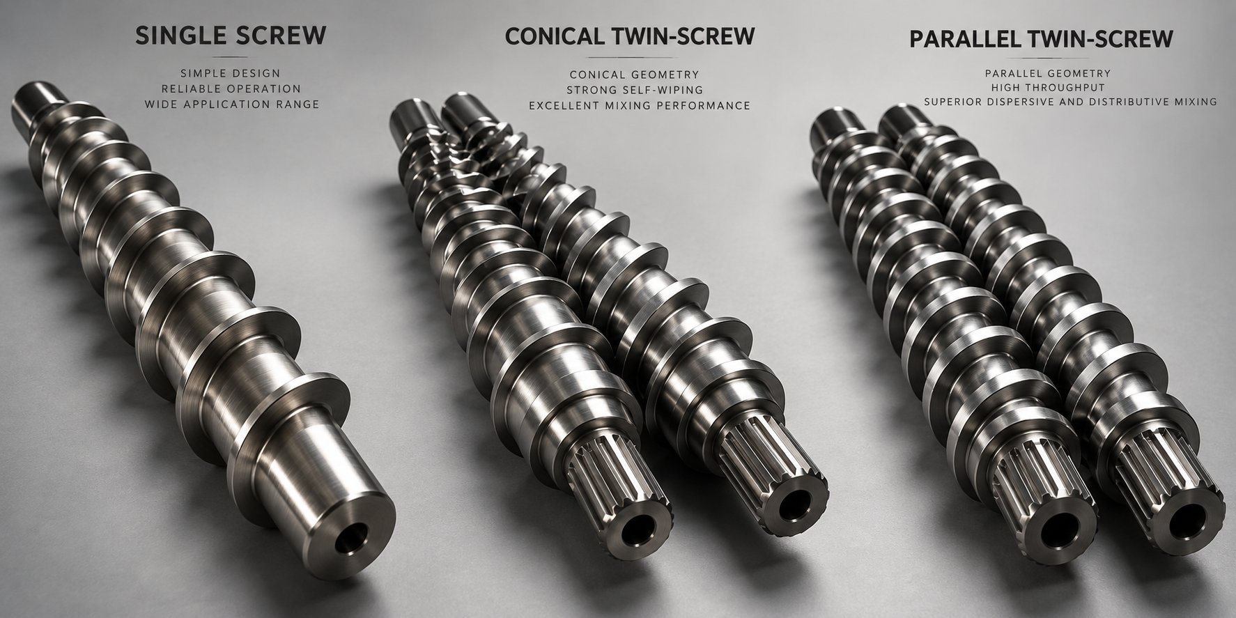
Single-Screw vs Twin-Screw Extruders for PVC Profiles
Three distinct extruder architectures compete for a place on the factory floor, and each handles PVC's thermal sensitivity and shear demands very differently. Picking the wrong one does not just cost money upfront — it locks you into processing limitations that show up in every meter of profile you produce. So which design fits which scenario?
Single-Screw Extruders and Their Limitations for PVC Profiles
A single-screw machine is the simplest and least expensive entry point. One rotating screw inside one barrel conveys, compresses, and plasticizes the compound. For materials like polyethylene or polypropylene — polymers with wide thermal windows and forgiving melt behavior — that simplicity works fine.
PVC is a different story. Single-screw designs rely heavily on barrel-wall friction to move material forward, and their mixing capability is inherently limited. You can add mixing pins or barrier flights to improve homogeneity, but the fundamental architecture still offers less precise shear control than a twin-screw alternative. In a real-world PVC extrusion process, that translates to a narrower operating envelope: harder to achieve full gelation uniformly, greater sensitivity to formulation shifts, and more difficulty maintaining tight wall-thickness tolerances on complex shapes.
Does that mean single-screw machines have no role? Not entirely. For simpler PVC extrusion profiles — basic edge banding, thin decorative strips, or low-output specialty runs — a single-screw extruder can deliver acceptable results at a lower capital cost. But for multi-cavity window profiles or any application where dimensional precision and surface finish are non-negotiable, production teams consistently reach for twin-screw technology.
Conical vs. Parallel Twin-Screw Extruders for PVC
Twin-screw extruders use two intermeshing, counter-rotating screws to convey and plasticize material. The forced-conveying mechanism gives them far better feeding consistency (especially with PVC dry blend), superior mixing, and more controllable shear input. Within this category, two geometries dominate: conical and parallel.
Conical twin-screw extruders taper from a large feed diameter to a smaller metering diameter. That taper creates natural compression without aggressive flight geometry, producing high torque at the intake and gentle, progressive plasticizing through the barrel length. For heat-sensitive PVC, this is a decisive advantage — the compound reaches full gelation with less risk of localized overheating. It is no coincidence that conical twin-screw machines remain the industry standard for PVC profile extrusion worldwide.
The quality and condition of the conical twin-screw barrel is central to this stability. Worn barrel linings lose compression efficiency, allowing melt to slip backward and creating temperature inconsistencies that degrade profile quality. When specifying or replacing barrels, manufacturers often turn to specialist suppliers like NANHAIYA, which engineers custom and replacement conical twin-screw barrels specifically for PVC profile extrusion — a practical sourcing option worth bookmarking if you are evaluating barrel condition on an existing line.
Parallel twin-screw extruders use two same-diameter screws arranged side by side. As Rollepaal's engineering team notes, parallel designs offer greater freedom in screw configuration and can be extended in length (for example, from 22D to 33-36D) to boost output — advantages that matter most on larger machines processing high volumes. However, achieving that higher throughput can introduce more shear heat, and the processing window for PVC can narrow if zone temperatures are not managed carefully. Parallel machines also tend to carry a higher investment cost, partly due to the more complex gearbox engineering required to transmit equal torque across two full-diameter shafts.
Three-Way Comparison at a Glance
The table below puts all three architectures side by side across the criteria that matter most when building a plastic profile extrusion line for PVC:
| Criteria | Conical Twin-Screw | Parallel Twin-Screw | Single-Screw |
|---|---|---|---|
| Mixing Quality | Excellent — forced conveying with progressive compression | Excellent — modular screw elements allow tailored mixing zones | Moderate — limited distributive mixing without special screw modifications |
| Shear Control | Very precise — taper geometry limits shear peaks | Good — but higher screw speeds can elevate shear heat | Limited — friction-dependent conveying makes shear less predictable |
| Output Capacity | Moderate to high (size-dependent, e.g., 65/132 to 92/188) | High — easier to extend barrel length for greater throughput | Low to moderate for PVC applications |
| PVC Suitability | Industry standard — optimized for heat-sensitive compounds | Suitable with careful temperature management | Acceptable for simple profiles only |
| Profile Complexity | High — handles multi-cavity and co-extruded designs well | High — parallel flexibility supports complex tooling | Low to moderate — best for basic cross-sections |
| Relative Investment Cost | Moderate | Higher | Lowest |
For the vast majority of PVC extrusion profiles — from window systems to cable management channels — the conical twin-screw extruder hits the sweet spot of plasticizing stability, shear safety, and cost efficiency. Parallel machines earn their place when throughput demands push beyond what a conical design can deliver at a given size class, and single-screw units remain a budget option for the simplest geometries.
Knowing which architecture fits your needs is only the first half of the equation. The real payoff comes from matching a specific extruder size and configuration to the exact profile you intend to produce — and that pairing looks very different for a multi-chamber window frame than it does for a length of decorative trim.
Common PVC Profile Types Matched to Extruder Configurations
You have picked your extruder architecture — most likely a conical twin-screw for rigid PVC. But which size class? Which die complexity? And how do the answers change depending on whether you are making a multi-chamber window frame or a simple length of skirting board? These are the practical questions that separate a well-matched pvc extrusion line from one that either loafs at half capacity or strains at its limits every shift.
The profiles themselves set the rules. Each geometry brings a unique combination of cross-sectional area, wall thickness, chamber count, and surface finish requirements — and those factors dictate the extruder output needed, the die engineering involved, and the downstream precision demanded. Let's break it down by application.
Window and Door System Profiles
If you want the most demanding test case for a PVC profile extruder, look no further than a modern multi-chamber window frame. Imagine a cross-section with five to seven hollow chambers separated by internal ribs as thin as 1.0 to 1.5 mm, all enclosed within outer walls that must hold tight dimensional tolerances for hardware fitment, weatherseal engagement, and structural load-bearing. This is the pinnacle of vinyl extrusion complexity.
Why are these profiles so challenging? Several factors compound at once:
- High melt volume demand — the large cross-sectional area of a multi-chamber frame requires substantial output, typically calling for conical twin-screw extruders in the 65/132 or 80/156 size class running at outputs of 200 to 500 kg/h.
- Complex multi-cavity dies — the die must split a single round melt stream into dozens of flow channels that fill every chamber, rib, and wall section at uniform velocity. Designing and balancing these dies is an engineering discipline unto itself.
- Extremely tight calibration — vacuum sizing tools for window profiles are machined to tolerances that leave almost no room for melt temperature variation or pressure fluctuation. Even a small drift in extruder output stability shows up as a wall-thickness deviation that fails quality inspection.
- Weld-line strength — where separate melt streams rejoin inside the die to form internal ribs, the weld lines must be mechanically sound. That demands perfectly homogeneous melt at uniform temperature — something only a well-maintained plasticizing system can deliver consistently.
Door frame profiles follow similar logic but often feature even larger cross-sections and thicker walls to handle heavier hardware loads. Some door systems also incorporate co-extrusion, where a secondary extruder feeds a different-colored or UV-stabilized cap layer onto the main profile. This adds another layer of process synchronization — both extruders must deliver stable, matched output to the co-extrusion die simultaneously.
As co-extrusion specialists explain, combining a tough core with a protective outer layer allows manufacturers to use recycled or lower-cost PVC internally while applying high-grade, impact-resistant material on the visible surface — boosting durability and aesthetics without inflating raw material costs across the entire profile.
Cable Trunking, Skirting, and Decorative Trim Profiles
Shift from window systems to cable management trunking, and the picture changes dramatically. A typical plastic PVC extrusion profile for cable trunking is a relatively simple U-channel or slotted tray — small cross-section, uniform wall thickness, and straightforward geometry. The die is far less complex, and the calibration tooling is simpler to manufacture and maintain.
These profiles typically run on smaller extruder models in the 51/105 or 55/110 size class, producing output in the 80 to 200 kg/h range. Line speeds tend to be higher because the profiles are lightweight and cool quickly, which means the cutting system and haul-off must keep pace. PVC trunking production lines often use multi-cavity dies — two-out or even four-out configurations — that extrude multiple profiles simultaneously from a single machine, maximizing throughput per line hour.
Skirting boards and decorative trims occupy a similar tier of complexity. Their cross-sections are typically solid or near-solid with contoured visible faces, meaning the die focuses on surface finish quality and dimensional consistency rather than internal chamber geometry. Corner trims, edge banding, and architectural moldings fall into this category as well — all shapes where aesthetics matter as much as mechanical performance.
Where things get more interesting is when decorative profiles require co-extrusion. Imagine a skirting board with a rigid white core but a woodgrain-textured cap layer, or a window trim with a colored outer surface over a recycled PVC substrate. These setups add a secondary (usually smaller) extruder feeding a thin cap layer through a co-extrusion die — a setup that demands good surface adhesion between layers and careful temperature matching to prevent delamination or surface defects.
Medical tubing profiles represent yet another niche. Though their cross-sections are simple, they impose strict cleanliness and contamination control requirements. Material handling must prevent cross-contamination, extruder components must be easy to disassemble and clean, and compounds may include flexible PVC formulations with different processing temperatures and lower compression ratio needs than rigid profiles.
Profile-to-Extruder Matching at a Glance
The table below maps the most common PVC profile applications to the extruder configurations that best serve them — a practical reference for anyone planning a new line or evaluating whether their current setup is correctly sized:
| Profile Type | Recommended Extruder Size Class | Die Complexity Level | Key Quality Considerations |
|---|---|---|---|
| Window frames | 65/132 to 80/156 | High — multi-cavity with internal mandrels and flow balancing | Wall-thickness uniformity, weld-line strength, co-extrusion compatibility |
| Door frames | 65/132 to 80/156 | High — large cross-section, often with hardware mounting channels | Structural rigidity, dimensional accuracy for hardware fitment, surface finish |
| Cable trunking | 51/105 to 55/110 | Low to moderate — simple U-channel, often multi-out dies (2 or 4 profiles) | Consistent slot dimensions for lid snap-fit, flame retardancy, high line speed |
| Skirting boards | 51/105 to 55/110 | Low to moderate — contoured face, solid or near-solid section | Surface smoothness, color consistency, straight-line accuracy |
| Decorative trims | 51/105 to 55/110 | Low to moderate — may include co-extrusion for cap layer or color | Aesthetic surface finish, tight dimensional tolerances for fit-and-finish applications |
| Medical tubing profiles | 51/105 to 55/110 | Low — simple circular or multi-lumen cross-sections | Contamination control, material purity, flexible PVC processing, clean disassembly |
A pattern emerges from this mapping: profile complexity and cross-sectional area drive the extruder size selection, while surface and structural quality requirements determine how tightly the entire line must be controlled. A cable trunking line and a window frame line may both use conical twin-screw technology, but their size classes, die investments, and calibration precision sit worlds apart.
Matching the right machine to the right product is a strong start — but the numbers on the extruder's specification sheet still need to be understood in context. Screw diameter, L/D ratio, output capacity, and motor power are not just figures to compare across quotations. Each one controls a specific aspect of melt quality, and knowing what they actually govern is what turns a specification comparison into an informed selection decision.
Key Technical Parameters Every Buyer Should Understand
Specification sheets for a PVC profile extruder can feel like alphabet soup — screw diameters expressed as ratios, L/D values, output figures in kg/h, motor ratings in kW, and a list of heating zones that may or may not mean anything without context. The problem is not a lack of numbers. It is a lack of explanation. What does each parameter actually control, and which ones deserve the most scrutiny when you are comparing two or three machines side by side?
Let's decode the key specs one by one, starting with the dimensions that define the heart of the machine.
Screw Diameter, L/D Ratio, and What They Control
Conical twin-screw extruders are identified by two numbers separated by a slash — for example, 51/105, 65/132, 80/156, or 92/188. The first number is the metering-end (small-end) diameter in millimeters, and the second is the feed-end (large-end) diameter. That taper is the defining feature of the conical design, and it has direct processing consequences.
A larger feed-end diameter means the screws can ingest more dry blend per revolution. Think of it as the intake capacity of the machine. The taper then compresses the material progressively as it travels toward the smaller metering end, generating the pressure needed to push homogeneous melt through the die. A bigger diameter spread between the two ends creates a steeper compression gradient — useful for high-bulk-density formulations that need more aggressive consolidation, but potentially risky for very heat-sensitive compounds that cannot tolerate sharp pressure spikes.
So what do the common size designations actually mean in practice?
- 51/105 — a compact machine suited for small profiles like decorative trims, edge banding, and cable trunking. Lower output range, smaller footprint, and lower capital cost.
- 65/132 — the versatile mid-range workhorse. Handles everything from skirting boards to medium-sized window profiles. This is the size class you will encounter most often on general-purpose PVC profile extrusion lines.
- 80/156 — steps up to larger cross-sections and higher throughput. Multi-chamber window frames and wide door profiles typically run on machines in this class.
- 92/188 — the high-output end of the spectrum, designed for large profiles or high-speed lines where maximum kg/h matters.
Alongside screw diameter sits the L/D ratio — the ratio of the screw's effective working length to a representative diameter (typically the average of the large and small ends for conical designs, as Kairong Group's technical team explains). You will commonly see L/D values between 22 and 28 for conical twin-screw machines used in plastic profile extrusion.
Why does this ratio matter? A longer L/D gives the compound more time and barrel length to absorb heat, mix uniformly, and reach full gelation before it exits into the die. The result is better melt homogeneity, which translates directly into more consistent wall thickness and smoother surfaces on the finished profile. However, a longer barrel also costs more, occupies more floor space, and increases the material's residence time inside the machine — a concern for PVC, where extended exposure to heat accelerates degradation.
The practical takeaway: do not automatically assume that a higher L/D is better. For standard rigid PVC window and door profiles, an L/D of 25 to 28 typically provides the right balance between plasticizing quality and thermal safety. Shorter ratios around 22 can work for simpler profiles with less demanding fusion requirements.
Output Capacity, Motor Power, and Heating Zones
Output capacity is quoted in kilograms per hour (kg/h), and it is the number most buyers fixate on first. That instinct is understandable — throughput directly determines how many meters of profile your line produces per shift. But output must be evaluated in context, not in isolation.
Imagine you need to produce a multi-chamber window profile weighing 1.8 kg per linear meter at a line speed of 3.5 m/min. That requires roughly 378 kg/h of extruder output just to keep up. If you also factor in startup scrap, purging losses, and the occasional speed adjustment for quality corrections, your machine needs comfortable headroom above that figure — say 420 to 450 kg/h. Buying a machine rated at exactly 380 kg/h leaves no margin and forces the extruder to run at its ceiling constantly, accelerating wear and narrowing your process window.
Motor power, measured in kilowatts, is what drives the screws. Higher power enables higher screw speeds and greater torque for processing stiff, high-viscosity PVC compounds. But raw kilowatt ratings tell only part of the story. The type of drive matters just as much. Modern servo drive systems — which have become standard on current-generation profile extruders — deliver several advantages over older AC vector drives:
- Energy savings of 20-40% during typical production cycles, because servo motors draw power proportional to actual load rather than running at fixed consumption.
- Faster, more precise speed response, which helps maintain stable melt pressure during the small output fluctuations that occur in normal operation.
- Lower heat generation in the drive system itself, reducing cooling demands on the factory floor.
Over a five- to seven-year ownership period, the energy cost difference between a servo-driven and a conventional-drive extruder can be substantial — often enough to offset the higher initial purchase price of the servo system.
Finally, there is the number and configuration of heating zones along the barrel and die. A typical conical twin-screw PVC profile extruder features four to six independently controlled barrel zones plus one or more die zones. Each zone has its own heater band (or cartridge heater) and thermocouple, managed by individual PID controllers.
Why does zone count matter? As extrusion process specialists at SHS note, each zone's temperature influences neighboring zones through heat transfer, and the displayed controller temperature often does not match the actual melt temperature at that point. More independently controlled zones give you finer resolution over the temperature gradient from feed throat to die exit — critical for PVC's notoriously narrow thermal processing window. Fewer zones force you to accept coarser control, which increases the risk of localized hot spots or cold spots that compromise melt quality.
A good rule of thumb: for rigid PVC profile extrusion, insist on at least five barrel heating-and-cooling zones plus independent die zone control. Lines running complex multi-chamber profiles or co-extrusion setups benefit from six or more zones, where the added granularity helps operators fine-tune the temperature curve to match specific compound behavior.
Parameter Priority for PVC Profile Extruder Selection
When you sit down to compare quotations, not every specification carries equal weight. Here is a ranked list reflecting the order of importance for selecting the right machine for PVC profile work:
- Screw geometry and size class — determines plasticizing quality, output range, and compound compatibility. This is the single most consequential choice.
- Number and independence of heating/cooling zones — controls your ability to manage PVC's tight thermal window zone by zone.
- Drive type and motor power — affects energy cost, speed stability, and torque headroom for demanding compounds.
- L/D ratio — influences melt homogeneity and residence time; must be matched to your compound and profile complexity.
- Rated output capacity (kg/h) — must exceed your calculated requirement by a comfortable margin, but is only meaningful when the four parameters above are already correct.
- Control system and automation level — PLC quality, HMI interface, data logging, and recipe management capabilities that affect day-to-day operability and troubleshooting speed.
Notice that output capacity — the number most buyers look at first — sits at position five. That is intentional. A machine with impressive throughput numbers but poor temperature zoning or an undersized screw design will produce fast, low-quality profiles. Getting the fundamentals right first ensures that the output figure on the specification sheet actually translates to usable, sellable product on your stacking table.
With these parameters decoded, the next logical question is how the melt stream actually gets shaped into a finished profile — and that answer lives inside the extrusion die and the temperature strategy that feeds it.
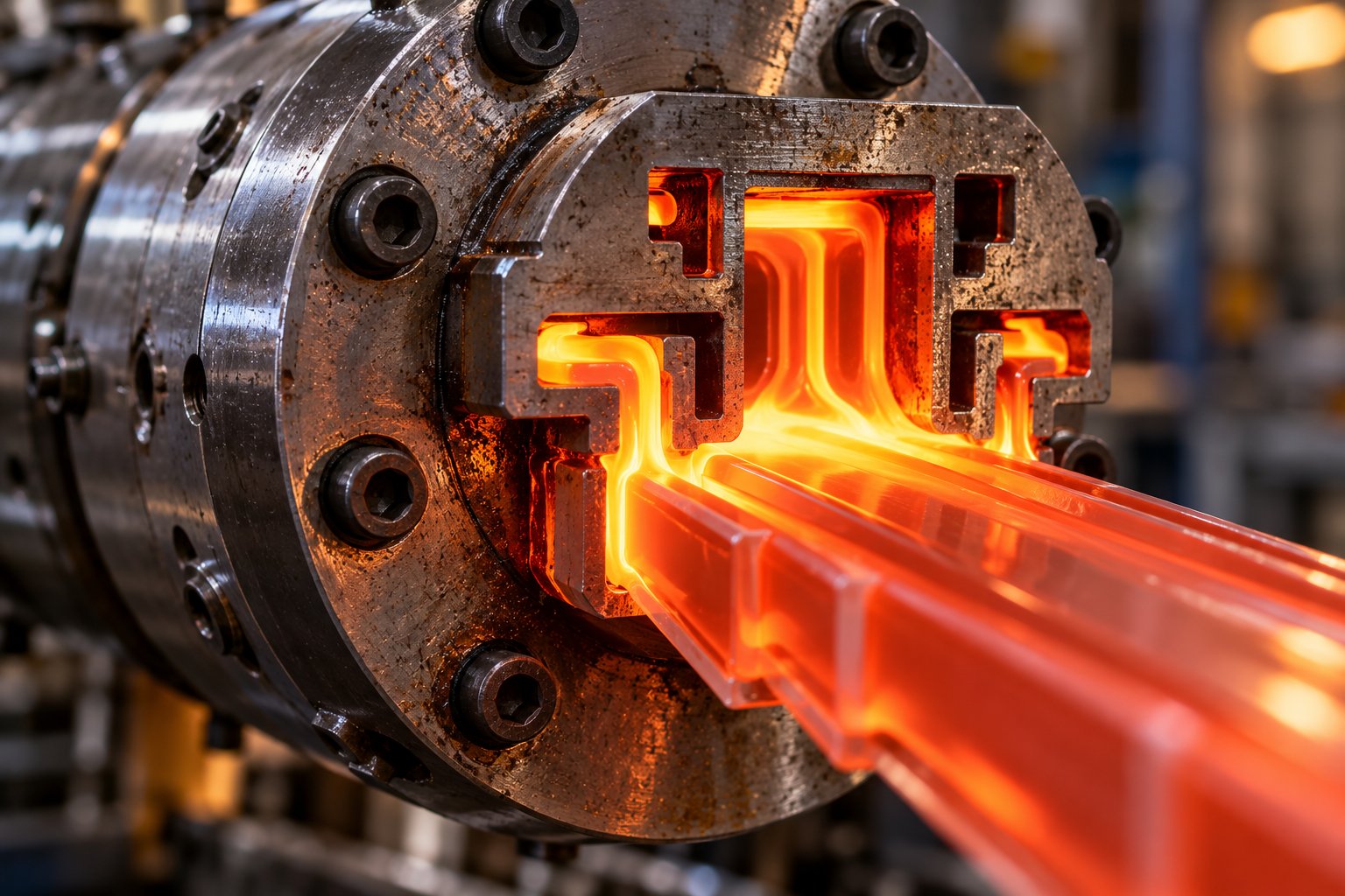
Die Design and Temperature Control in PVC Extrusion
The extruder plasticizes compound into a homogeneous melt. The downstream equipment cools, sizes, and cuts. But between those two stages sits the component that defines the entire product: the extrusion die. Everything upstream exists to feed it a perfect melt stream, and everything downstream exists to preserve the shape it creates. If the die's internal geometry is wrong — or if the temperature profile feeding it is off — no amount of calibration wizardry downstream will save the profile.
Die Design Principles for PVC Profile Geometry
Think of the die as a translator. It receives a round, pressurized melt stream from the barrel and reshapes it into the exact cross-section you need — whether that is a simple rectangular cable trunking channel or a seven-chamber window frame bristling with internal ribs. That translation happens inside a precisely machined steel flow channel, and two design variables control whether it works or fails: flow balancing and land length.
Flow balancing ensures that melt exits the die at uniform velocity across the entire cross-section. Why is this critical? Wherever the profile has both thick and thin wall sections, the thicker areas naturally offer less flow resistance, so melt rushes through them faster. Left uncorrected, faster-flowing sections stretch while slower sections starve — producing uneven wall thickness, internal stress, and visible warping once the profile cools. Tooling engineers compensate by lengthening the land in fast-flow regions or inserting flow restrictors upstream, forcing the melt to equalize before it exits. For complex profile extrusion plastic geometries — multi-cavity window frames, for instance — this balancing process can take weeks of iterative die trials before production-grade uniformity is achieved.
Land length is the final parallel section of the die opening, where the melt flows through a channel whose cross-section matches the target profile shape. It serves two purposes. First, the land stabilizes the melt flow, giving the polymer enough residence time in the finished geometry to "remember" its shape before it exits into open air. Second, a properly sized land improves surface quality by smoothing out velocity irregularities from upstream. A common starting guideline is a land-length-to-wall-thickness ratio of roughly 10:1 — so a 2 mm wall section calls for approximately 20 mm of land. Too short, and the process becomes hypersensitive to temperature and speed fluctuations. Too long, and excessive pressure drop can create uneven cooling and residual stress inside the profile.
PVC adds a unique wrinkle to die design: die swell behavior. When most polymers exit the die, the melt relaxes and swells outward — sometimes dramatically. Longer die lands reduce that swell by giving the melt more time to relax inside the channel. PVC, however, behaves differently. Because its flow during processing is particulate rather than purely molecular, the surface interaction between primary particles is relatively low. The result is that die swell in rigid PVC is comparatively independent of land length and shear rate — a behavior unlike virtually any other common thermoplastic. This means die designers for PVC profile extruders rely more heavily on adjusting the die gap and compression geometry rather than simply extending land length to control extrudate dimensions. Factors like acrylic process aid level, internal lubricant ratio, and back pressure within the die all shift die swell more meaningfully than land length changes do.
One more principle deserves attention: dead zones. Any area inside the die where melt can stagnate — a sharp corner in a flow channel, a poorly transitioned adapter section — becomes a degradation trap. Stagnant PVC sits at processing temperature far longer than it should, eventually decomposing into black specks and discolored streaks that contaminate the profile. Die channels must maintain full compression and smooth transitions throughout, with no pockets where material can hang up.
Temperature Zone Strategy Along the Extruder Barrel
A perfectly designed die still produces defective profiles if the melt feeding it arrives at the wrong temperature — or worse, at an uneven temperature. That is why temperature zoning along the barrel is not a set-and-forget exercise. It is a deliberate strategy, and for PVC, it demands more precision than for almost any other polymer.
Here is how a typical zone-by-zone temperature profile works on a conical twin-screw PVC profile extruder, based on standard processing guidelines:
| Barrel Zone | Typical Temperature Range | Purpose |
|---|---|---|
| Feed zone | 150-165 °C | Preheat and convey dry blend without premature melting; too hot causes bridging, too cold spikes torque |
| Compression zone | 165-175 °C | Gradually consolidate and begin plasticizing the compound under increasing screw compression |
| Metering zone | 170-185 °C | Complete plasticizing and homogenize the melt; overheating here causes degradation and discoloration |
| Adapter / Die zone | 175-190 °C | Maintain melt fluidity for uniform die filling; too low roughens the surface, too high causes melt sagging |
Notice the pattern: temperatures rise gradually from the feed end toward the die, but the total spread across all zones is remarkably narrow — often just 25 to 35 °C from start to finish. Compare that to polyethylene extrusion, where barrel temperatures might swing 60-80 °C from feed to die without consequence. That compressed range is a direct reflection of PVC's chemistry.
The feed zone is set conservatively to avoid two problems. If it runs too hot, PVC powder softens prematurely and clings to the screw flights, forming a bridge that blocks fresh material from entering — starving the extruder and causing output surges. If it runs too cold, the dry blend resists compression, torque spikes upward, and the motor draws excessive current. Either scenario disrupts the steady melt delivery that the die depends on.
Through the compression and metering zones, temperature climbs just enough to complete gelation. The danger here is localized overheating — a thermocouple that reads 175 °C on the controller display does not guarantee that the actual melt temperature at the screw flight tip matches that reading. Frictional shear heat generated inside the screw channel adds energy that barrel heaters cannot measure. This is precisely why experienced operators monitor torque readings and melt pressure alongside zone temperatures: a sudden torque drop, for instance, often signals that the melt has become over-plasticized before any thermocouple registers a problem.
At the die, the temperature must be high enough for smooth flow filling every channel of the profile geometry, yet low enough to preserve the melt strength needed for the extrudate to hold its shape between the die exit and the first calibration contact. A die zone that runs too cold produces rough, shark-skin-like surfaces. A die zone that runs too hot lets the soft extrudate sag or deform under its own weight before calibration can intervene.
PVC requires the narrowest thermal processing window of any common extrusion thermoplastic — typically just 25-35 °C separates incomplete fusion from active degradation, making independent, zone-by-zone temperature control not optional but essential.
This is why the earlier discussion on heating zone count matters so much in practice. Five or six independently controlled barrel zones — each with its own heater, cooling fan, and PID loop — give operators the resolution to sculpt a smooth, precise thermal gradient within that razor-thin window. Fewer zones mean coarser control, wider temperature variation between setpoints, and a higher probability that some portion of the melt enters the die either under-fused or on the edge of degradation.
Die design and temperature strategy are, in effect, two halves of the same quality equation. A brilliantly balanced die cannot compensate for melt that arrives at inconsistent temperature, and a flawless temperature profile cannot fix a die with dead zones or poor flow distribution. When both are dialed in together, the result is a stable, repeatable process that turns out dimensionally accurate profiles with clean surfaces shift after shift.
Of course, even well-tuned lines encounter problems. Surface roughness appears without warning, wall thickness drifts, or mysterious burn marks show up on random lengths. Tracing those defects back to their root cause — and knowing which corrective lever to pull — is where operational knowledge separates productive lines from frustrating ones.
Troubleshooting Common PVC Profile Extrusion Defects
A well-tuned PVC profile machine can run for hours producing flawless output — and then, seemingly out of nowhere, something goes wrong. The surface turns rough. A burn mark streaks across a batch of profiles. Wall thickness drifts outside tolerance. Every experienced operator knows the feeling, and every new operator dreads it.
The instinct is to start turning dials: bump the temperature up, slow the screw speed down, adjust the haul-off. But reacting before diagnosing almost always makes things worse. As extrusion troubleshooting specialists emphasize, stacked changes make the real cause harder to identify because extrusion has delayed responses — a temperature adjustment may take minutes to show its effect in the finished product. The smarter approach is to name the defect, trace it to its most likely origin, and make one controlled correction at a time.
Let's walk through the defects you are most likely to encounter on a PVC profile extrusion line, split into two categories: what you can see on the surface, and what is hiding inside the cross-section.
Surface Defects and Their Extruder-Related Causes
Surface quality is the first thing an inspector — or a customer — notices. Three surface defects dominate PVC plastic extrusion troubleshooting logs, and each points to a different root cause inside the machine.
Shark skin appears as a rough, scaly, or finely cracked texture on the profile's outer surface, typically visible right at the die exit. The underlying cause is excessive shear stress at the die lip. When the melt velocity exceeds a critical threshold, the outer skin of the extrudate fractures as it exits the land section. Improper die temperature — too low — increases melt viscosity and amplifies shear stress, making the problem worse. What should you check first? Raise the die zone temperature gradually, reduce screw RPM or line speed, and inspect the die lip for buildup or physical damage. If the roughness persists in a fixed location regardless of speed changes, the die land surface itself may need polishing or reconditioning.
Melt fracture is shark skin's more severe cousin. Instead of fine roughness, you see gross distortion — wavy, irregular surfaces or spiraling patterns that make the profile dimensionally useless. This happens when extrusion speed or melt pressure exceeds what the compound's rheology can handle. Inadequate melt homogeneity — from insufficient plasticizing or poor mixing upstream — compounds the problem because regions of under-fused compound behave unpredictably as they pass through the die restriction. The corrective path starts with reducing output rate and verifying that the melt is fully homogeneous before it reaches the die. If the defect recurs at speeds that should be manageable, the screw's mixing capability or the barrel's compression efficiency may need evaluation.
Discoloration and burn marks are the telltale signs of thermal degradation — and with PVC, they demand immediate attention because they signal active decomposition of the polymer. Brown or black streaks, yellowish tinting, or localized dark spots all point to compound that has been exposed to excessive heat for too long. The sources vary: a barrel hot spot from a failing heater band or miscalibrated thermocouple, excessive residence time caused by low throughput or an oversized barrel for the application, or — critically — dead zones inside the barrel, adapter, or die where stagnant material degrades and periodically breaks free into the melt stream. Worn screws and barrels are a frequent but often overlooked contributor: as flight clearances open up from wear, material slips backward and recirculates, spending far longer at processing temperature than the formulation's stabilizer package can protect against.
Dimensional Defects and Internal Quality Issues
Surface problems are visible at a glance. Dimensional and internal defects are sneakier — they may not show up until profiles fail quality checks, assembly trials, or worse, field performance.
Uneven wall thickness is one of the most common dimensional complaints in profile extrusion. When you measure a cross-section and find one wall 0.3 mm thicker than the opposite side, the cause could be upstream or downstream — or both. Inside the extruder, inconsistent melt temperature across the die creates regions of different viscosity, so melt flows faster through hotter (lower-viscosity) sections and slower through cooler ones. Die flow imbalance — where the internal channel geometry does not distribute melt evenly — produces the same effect. Downstream, vacuum calibration misalignment or uneven cooling pulls the profile off-center. The diagnostic key: if the thickness asymmetry is already visible at the die exit, the problem is in the die or the melt condition. If it appears only after calibration, look at the sizing and cooling stations first.
Voids and bubbles inside the profile walls compromise structural integrity and impact strength, even when the surface looks fine. The most common culprit is moisture. PVC dry blend absorbs ambient humidity, and even small moisture levels vaporize inside the hot barrel, creating gas pockets that travel through the die and freeze into the profile during cooling. Inadequate venting in the barrel — or a blocked vacuum vent port — traps volatiles that should escape before the melt reaches the die. Excessive lubricant levels in the compound formulation can also generate gas. The first corrective step is always verifying that material has been properly dried and stored, and confirming that vent zones are functioning and unobstructed.
Warping shows up after the profile cools — lengths that should lie flat develop a twist or bow. Uneven cooling is the usual suspect: if one side of the profile loses heat faster than the other in the calibration or cooling tank, differential shrinkage pulls the shape out of true. But warping can also originate upstream. Poor plasticizing — where some regions of the melt are better fused than others — creates uneven internal stress that relaxes unevenly as the profile cools. In this scenario, the root cause lives inside the screw and barrel, not at the cooling station.
Defect-to-Cause-to-Fix Reference Table
When a defect appears on the line, speed matters. The table below gives you a single-page diagnostic map — match the symptom, check the probable cause, and apply the recommended corrective action before making additional changes:
| Defect | Probable Cause(s) | Recommended Corrective Action |
|---|---|---|
| Shark skin (rough, scaly surface) | Excessive die shear stress; die temperature too low; damaged or dirty die lip | Increase die zone temperature gradually; reduce screw RPM or line speed; clean and polish die lip |
| Melt fracture (gross surface distortion) | Extrusion speed too high; poor melt homogeneity; inadequate plasticizing | Reduce output rate; verify melt uniformity; check screw mixing capability and barrel compression |
| Discoloration or burn marks | Barrel hot spots; excessive residence time; dead zones in barrel/die; worn screw and barrel | Check heater bands and thermocouples; purge dead zones; inspect screw flight clearances; reduce residence time by matching extruder size to throughput |
| Uneven wall thickness | Die flow imbalance; inconsistent melt temperature; vacuum calibration misalignment | Rebalance die flow channels; verify zone-by-zone melt temperature uniformity; realign calibration tooling |
| Voids and bubbles | Moisture in compound; inadequate barrel venting; excessive lubricant in formulation | Dry material to specification; clear and verify vent ports; review compound formulation with supplier |
| Warping or bowing | Uneven cooling; poor plasticizing causing internal stress; asymmetric die flow | Equalize cooling water distribution; improve melt homogeneity through screw/barrel condition; adjust die for symmetric flow |
The Common Thread: Screw and Barrel Condition
Look across the table and you will notice a pattern. Burn marks trace back to worn screw flights allowing stagnant material. Melt fracture connects to inadequate plasticizing from a barrel that has lost compression. Uneven wall thickness links to inconsistent melt quality. Warping ties to poor fusion. Multiple defect categories converge on one root cause: the condition of the screw and barrel assembly.
As screws wear, the clearance between flight tips and barrel bore widens. Material that should be pushed forward instead leaks backward over the flights, reducing effective compression and creating pockets of over-processed compound. The profile extrusion machine gradually loses its ability to deliver the consistent, fully fused melt that the die and downstream equipment depend on. Output drops, energy consumption climbs, and defect rates creep upward — often so gradually that operators compensate with temperature and speed adjustments without realizing the hardware itself is the problem.
A practical rule: if multiple defects from the table above appear simultaneously or worsen progressively over weeks, stop chasing individual symptoms and inspect the screw and barrel first. Measuring flight-tip clearances and comparing them against the manufacturer's original specifications will tell you whether the plasticizing system has degraded past the point where process adjustments alone can compensate.
Knowing how to diagnose defects is essential — but preventing them in the first place depends on choosing the right extruder size for your production needs and maintaining it before wear becomes a crisis. That is where intelligent machine selection and a disciplined maintenance plan pay their biggest dividends.
How to Select and Maintain the Right PVC Profile Extruder
Diagnosing defects is a reactive skill. Choosing the right machine and keeping it in peak condition is how you avoid most of those defects in the first place. Yet the selection process trips up even experienced buyers — partly because the purchase price grabs all the attention while the factors that actually determine long-term profitability hide in operating costs, wear rates, and maintenance cycles that play out over years.
Let's work through the decision from both angles: how to size the extruder correctly before you buy, and how to protect that investment once it is running on your floor.
Matching Extruder Size to Your Production Requirements
The sizing process works backwards. You do not start with a machine catalog and pick an appealing model. You start with your product, your target volumes, and your line speed — and let those numbers point you toward the correct size class.
Here is the logic chain, step by step:
- Define your profile geometry and weight per meter. A multi-chamber window frame might weigh 1.6 to 2.2 kg/m, while a cable trunking channel might weigh just 0.3 to 0.5 kg/m. This single figure anchors every calculation that follows.
- Set your target line speed. Window profiles typically run at 1.5 to 4.0 m/min depending on cross-section complexity and cooling capacity. Lighter profiles like trims and trunking can run faster — sometimes 8 to 12 m/min on multi-cavity dies.
- Calculate the required output in kg/h. Multiply the profile weight per meter by the target line speed (converted to meters per hour). A 1.8 kg/m window profile at 3.0 m/min needs 1.8 x 180 = 324 kg/h.
- Add a headroom margin of 15-25%. You need breathing room for startup purging, speed adjustments during quality corrections, and the inevitable small fluctuations in compound bulk density. That 324 kg/h target becomes roughly 375 to 405 kg/h of required machine capacity.
- Match the capacity to a conical twin-screw size class. This is where the common designations map to your numbers.
The four standard conical twin-screw size classes each occupy a distinct performance envelope. Picking between them is not just about hitting the output number — it is about matching the machine's plasticizing capability to the thermal and shear demands of your specific compound and profile geometry.
| Size Class | Typical Output Range (kg/h) | Best Suited For |
|---|---|---|
| 51/105 | 80 - 180 | Small profiles: decorative trims, edge banding, thin cable trunking, medical tubing |
| 65/132 | 200 - 350 | Versatile mid-range: skirting boards, medium window profiles, general-purpose profile extrusion equipment |
| 80/156 | 300 - 500 | Larger profiles: multi-chamber window frames, wide door systems, heavy-wall trunking |
| 92/188 | 450 - 800+ | High-output applications: large-section profiles, high-speed lines, or dual-strand extrusion PVC setups |
A common mistake? Over-sizing. Buying a 92/188 machine for a product that only needs 280 kg/h sounds like future-proofing, but it creates real problems. An oversized extruder running at a fraction of its capacity means longer residence time inside the barrel — and for heat-sensitive PVC, extended residence time accelerates degradation. You end up fighting discoloration and compound breakdown that a correctly sized machine would never produce. As industry selection guides emphasize, under-sizing forces the motor and gearbox to their limits and accelerates mechanical wear, while over-sizing wastes energy and invites thermal degradation. The sweet spot is a machine whose rated output gives you 15-25% headroom above your calculated requirement — no more, no less.
One more sizing consideration that buyers often overlook: if you plan to run multiple profile types on the same line (say, window frames during the day shift and skirting boards at night), the extruder must handle the most demanding product comfortably. You can always dial a larger machine down for simpler profiles, but you cannot push a smaller machine beyond its thermal and mechanical limits for complex ones without paying the price in quality and wear.
Total Cost of Ownership and Maintenance Planning
Imagine two machines on a quotation sheet. Machine A costs 15% less upfront. Machine B has servo drives, bimetallic barrel linings, and a more sophisticated control system. Which one is cheaper? The answer depends entirely on what happens over the next five to ten years — and most of those costs have nothing to do with the purchase price.
Total cost of ownership for a PVC profile extruder breaks down into four major buckets:
- Energy consumption — the single largest ongoing cost. A servo-driven extruder running 6,000 hours per year at a 20-30% energy reduction versus an older AC-drive model saves tens of thousands of dollars annually. Over a seven-year ownership cycle, the cumulative energy savings can exceed the entire price difference between the two machines. Always request verified kWh-per-kg figures from suppliers, and compare them at your actual operating conditions — not at best-case catalog speeds.
- Material waste — startup purging, product changeover scrap, and reject rates during steady-state production all eat into margins. Modern PLC systems with stored recipe management cut changeover time and waste dramatically by automating the parameter transition from one product to the next. Gravimetric feeding further reduces material loss by maintaining precise dosing regardless of compound density variations.
- Maintenance intervals and spare parts — barrel heaters, thermocouples, gearbox oil, haul-off belts, and cutting blades are consumables with predictable replacement cycles. Less predictable — but far more impactful — is the condition of the screw and barrel assembly, which degrades gradually under the combined attack of abrasive fillers, corrosive HCl gas, and the relentless mechanical stress of processing stiff PVC compounds.
- Downtime cost — every hour the line sits idle costs you the margin on the product you are not producing. Unplanned breakdowns are exponentially more expensive than scheduled maintenance stops because they often cascade: a seized screw damages the barrel bore, which requires weeks of lead time for replacement, which stalls your delivery commitments.
The maintenance dimension deserves special attention because it is where disciplined operators protect their investment and where neglectful ones destroy it. Here is a practical checklist of the key maintenance actions and their recommended intervals:
- Daily: Check barrel zone temperatures against setpoints; verify melt pressure and torque readings are within normal range; inspect haul-off belt condition and tension; confirm vacuum calibration pump pressures.
- Weekly: Inspect die lip and calibrator surfaces for buildup or scoring; verify thermocouple accuracy by cross-referencing with a handheld pyrometer; check gearbox oil level and condition; clean any material buildup around the feed throat and hopper.
- Monthly: Lubricate all drive chain and bearing points per manufacturer specifications; inspect heater band connections and insulation covers for damage; verify cooling water flow rates and temperatures at each calibration and cooling station; review production data logs for gradual drift in torque, pressure, or output weight that could indicate developing wear.
- Quarterly: Perform a thorough die disassembly, cleaning, and inspection — check flow channels for pitting, corrosion, or material hang-up; inspect cutting saw blades and replace if edge quality has degraded; test emergency stop circuits and safety interlocks.
- Annually (or per manufacturer schedule): Pull the screws and measure flight-tip clearances against original specifications; inspect barrel bore for wear, scoring, or corrosion; evaluate gearbox condition including thrust bearing play and gear tooth wear; recalibrate all thermocouples and pressure transducers.
That annual screw-and-barrel inspection is the most important check on the entire list. As maintenance specialists at Turner Group point out, worn barrels lead to uneven heat distribution and temperature fluctuations that directly degrade product quality, while worn screw flights lose compression efficiency — reducing melt homogeneity and driving up energy consumption as the motor works harder to push material through an increasingly sloppy plasticizing system. The trouble is that screw and barrel wear creeps in gradually. Operators compensate by nudging temperatures up a degree here, slowing line speed a fraction there. By the time someone finally pulls the screws for measurement, the flight clearances may be double or triple their original values.
A practical guideline from industry experience: bimetallic screws and barrels on PVC profile lines running abrasive calcium-carbonate-loaded compounds typically need refurbishing or replacement every three to five years, though this interval shortens with higher filler loading or aggressive formulations. Nitrided components may wear faster, especially on high-output lines in the 80/156 and 92/188 size classes where throughput and filler content push mechanical stress higher.
When the time comes for replacement, sourcing matters. A generic barrel that does not match the original metallurgy, bore tolerances, or taper geometry will underperform from day one — and may accelerate wear on the new screws you install alongside it. This is where working with a specialist supplier pays for itself. NANHAIYA, for example, focuses specifically on custom and replacement conical twin-screw barrels for PVC pipe, PVC profile, PVC board, foam board, and WPC extrusion manufacturers. Their barrels are engineered to match the plasticizing requirements of each application, which means the compression characteristics and corrosion resistance align with what your specific compound and machine platform demand. If you are planning a scheduled barrel replacement or evaluating whether your current barrels have reached end-of-life, having a dedicated supplier in your maintenance network reduces lead time and keeps production downtime to a minimum.
One final perspective that ties selection and maintenance together: the best machine is the one you can keep running at peak performance, not just the one with the most impressive specification sheet. A well-maintained 65/132 extruder with fresh barrels and properly profiled screws will outperform a neglected 80/156 every day of the week — producing tighter tolerances, cleaner surfaces, lower scrap, and more consistent output per kilowatt of energy consumed. The purchase decision gets you in the door. The maintenance discipline determines whether you stay profitable once you are through it.
Frequently Asked Questions About PVC Profile Extruders
1. What type of extruder is best for PVC profile extrusion?
The conical twin-screw extruder is the industry standard for rigid PVC profile extrusion. Its tapered screw geometry creates natural compression that delivers high torque at the feed zone and gentle, progressive plasticizing through the barrel. This design minimizes the risk of localized overheating — a critical advantage given PVC's narrow thermal processing window, where only 25-35 degrees Celsius separates incomplete fusion from active degradation. Single-screw extruders may work for simple profiles, but conical twin-screw machines offer superior mixing, shear control, and dimensional consistency for complex shapes like multi-chamber window frames.
2. What is the difference between conical and parallel twin-screw extruders for PVC?
Conical twin-screw extruders taper from a larger feed diameter to a smaller metering diameter, providing progressive compression that suits heat-sensitive PVC compounds. They offer precise shear control at a moderate investment cost and handle complex multi-cavity profiles well. Parallel twin-screw extruders use two same-diameter screws and can be extended in barrel length for higher throughput, but they may generate more shear heat and typically carry a higher purchase price due to more complex gearbox engineering. For most PVC profile applications, conical designs hit the optimal balance of plasticizing stability, safety, and cost efficiency.
3. How do I choose the right size PVC profile extruder for my production needs?
Start by calculating your required output: multiply the profile's weight per meter by your target line speed in meters per hour, then add a 15-25% headroom margin. Match that figure to a conical twin-screw size class. A 51/105 handles 80-180 kg/h for small trims and trunking. The 65/132 covers 200-350 kg/h as a versatile mid-range option. The 80/156 reaches 300-500 kg/h for larger window and door profiles. The 92/188 pushes 450-800+ kg/h for high-output lines. Avoid over-sizing, as running an extruder at a fraction of its capacity increases PVC residence time and risks thermal degradation.
4. What causes burn marks and discoloration in PVC profile extrusion?
Burn marks and discoloration signal thermal degradation of PVC, where the polymer releases corrosive hydrochloric acid gas. Common causes include barrel hot spots from failing heater bands or miscalibrated thermocouples, excessive residence time from low throughput or an oversized machine, and dead zones inside the barrel, adapter, or die where stagnant material degrades and periodically contaminates the melt stream. Worn screws and barrels are a frequently overlooked contributor — widened flight clearances allow material to recirculate and overheat. Inspecting screw flight-tip clearances against original specifications is a critical first step when discoloration appears.
5. How often should screw and barrel assemblies be inspected on a PVC profile extruder?
A full screw-and-barrel inspection — pulling the screws and measuring flight-tip clearances against the manufacturer's original specifications — should be performed at least annually. On PVC lines running abrasive calcium-carbonate-loaded compounds, bimetallic screws and barrels typically need refurbishing or replacement every three to five years, with shorter intervals for high-filler or aggressive formulations. Gradual wear is difficult to detect in daily operation because operators compensate with small temperature and speed adjustments. Specialist barrel suppliers like NANHAIYA (nhyscrews.com) offer custom replacement conical twin-screw barrels engineered for PVC profile extrusion, helping minimize downtime during scheduled replacements.
Written by
Nanhaiya Technical Team
Zhoushan Nanhaiya Plastic Machinery Co., Ltd.
The Nanhaiya technical team supports screw and barrel manufacturing projects through application review, technical communication, custom manufacturing coordination, and production and quality control.
Discuss Your Application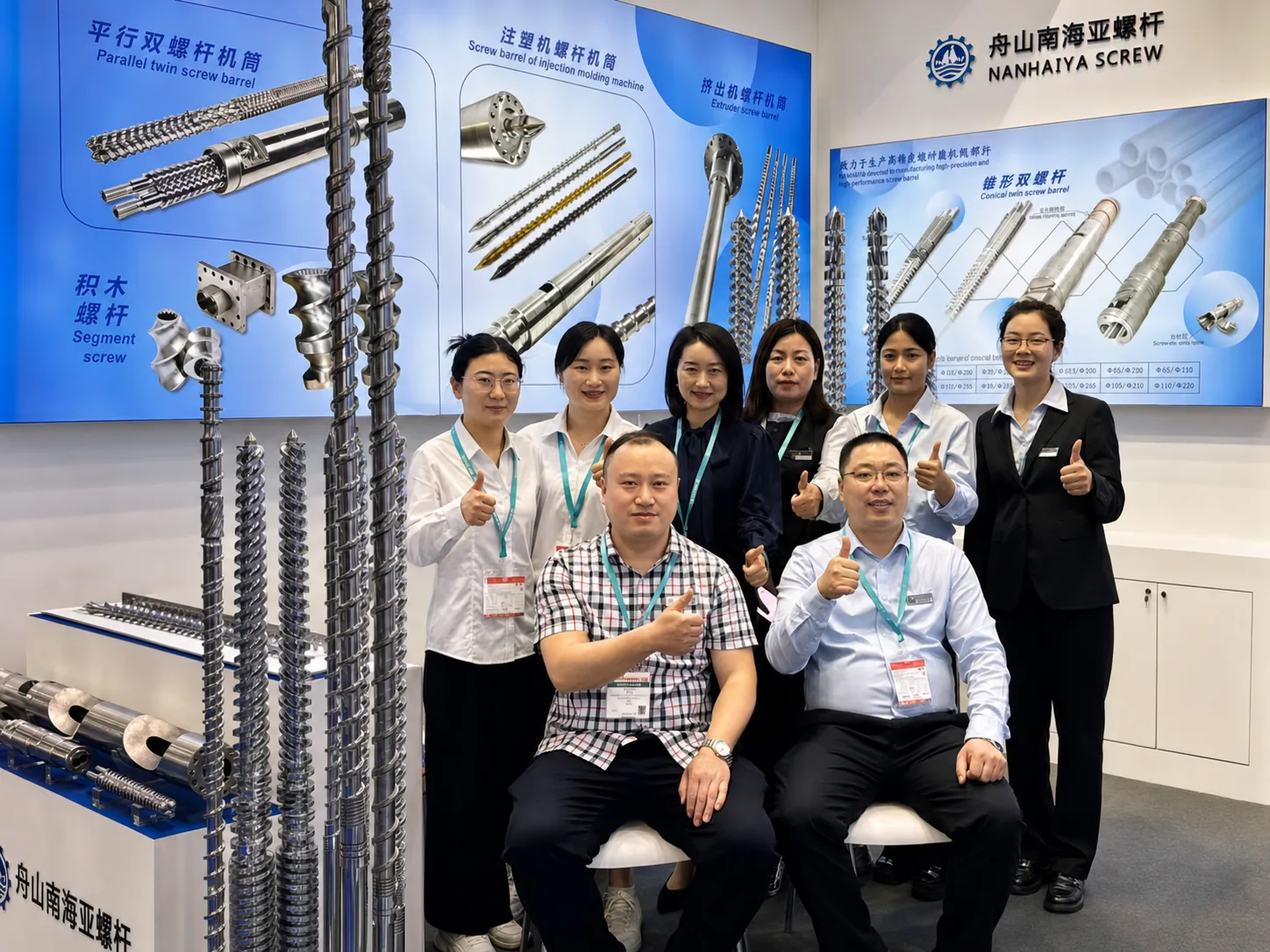
Related Articles
More insights on screw barrel technology and plastics processing.
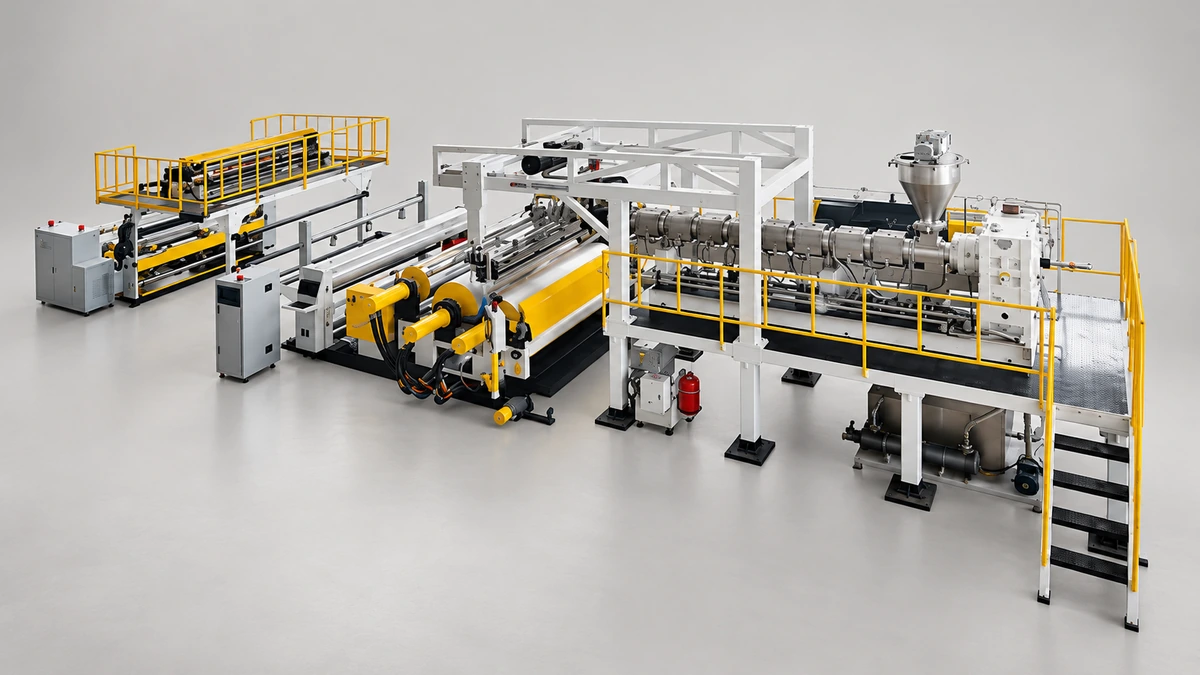
Plastic Sheet Extrusion Line Mistakes That Silently Kill Your Margins
Nov 3, 2026
Avoid costly plastic sheet extrusion line mistakes. Learn component specs, die design, polymer configs, screw selection, and troubleshooting to protect margins.
Read Article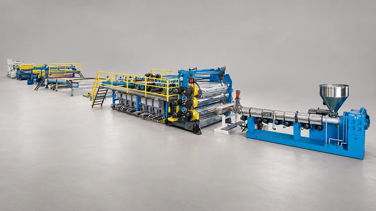
Sheet Extrusion Troubleshooting: Trace Every Defect to Its Root Cause
Nov 2, 2026
Master sheet extrusion troubleshooting with a systematic defect diagnosis framework. Fix orange peel, gauge variation, gels, flatness issues, and co-extrusion problems fast.
Read Article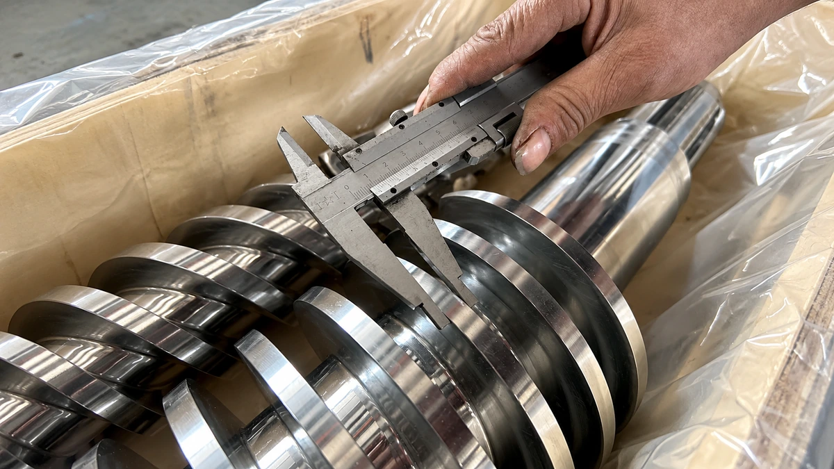
Extrusion Screw Compression Ratio: The Math Most Processors Get Wrong
Nov 2, 2026
Learn how to calculate extrusion screw compression ratio correctly, compare geometric vs. effective ratios, and match compression to every common thermoplastic.
Read ArticleLooking for something else?
Search by material, symptom or product and jump straight to the relevant page.
These are navigation suggestions based on keyword matching — not a quotation, not a delivery commitment, and not a substitute for engineering review. Final specification is confirmed by our engineers against your drawings and processed material.
Need help with screw barrel selection?
Share your machine model, processed material and application. Our team can help with pricing and technical support.