

Why Sheet Extrusion Troubleshooting Requires a Systematic Approach
Imagine you are running a polymer sheet extrusion line and a subtle haze appears across the entire sheet width. You bump up barrel temperatures, tweak the screw speed, and adjust the die lip gap — all within ten minutes. The haze persists, and now you have introduced a new gauge variation problem. Sound familiar? This scenario plays out daily in sheet extrusion plants because operators default to trial-and-error adjustments instead of following a structured diagnostic process.
Sheet extrusion troubleshooting is the discipline of tracing every defect on a flat, continuous sheet back to a specific root cause — then applying a targeted correction. It differs fundamentally from profile, pipe, or blown-film troubleshooting because of the sheer visibility and variety of defects that flat sheet exposes. Width-spanning gauge bands, surface blemishes that cover large visible areas, and downstream thermoforming failures all demand their own diagnostic logic. A pipe extruder operator worries about wall concentricity; a blown-film operator focuses on bubble stability. In sheet extrusion, you are managing quality across a wide, flat surface where every imperfection is immediately obvious.
The most reliable approach follows a clear hierarchy: check the material first, then the machine condition, then the process parameters. Skipping straight to process adjustments — the most common instinct — often masks the real problem and creates secondary defects.
Every sheet defect is either cross-direction, machine-direction, or random — and that classification alone narrows possible root causes by more than half.
What Makes Sheet Extrusion Troubleshooting Unique
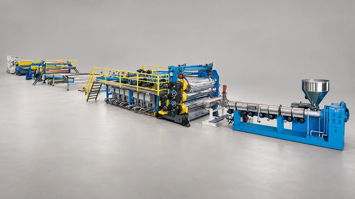
A sheet extrusion line stretches from the resin hopper all the way to the winder or stacking station. That is a lot of equipment, and a significant share of defects originate downstream of the extruder — at the chill rolls, trim stations, thickness gauges, or winders. Yet operators frequently blame the extruder or die for problems actually caused by improper chill roll contact, uneven winder tension, or a drifting thickness gauge feedback loop. Recognizing that the entire line contributes to sheet quality is the first step toward effective diagnosis. In polypropylene extrusion, for example, a chill roll set just a few degrees too high can shift crystallinity enough to produce haze — a defect that looks like a melt problem but has nothing to do with the screw or barrel.
The Symptom-First Diagnostic Framework
Rather than listing every possible cause and hoping one fits, effective troubleshooting starts with classifying the defect into one of three categories:
- Cross-direction (CD) defects — These appear as bands or variations spanning the sheet width. A classic example is gauge bands caused by uneven die lip adjustment or non-uniform die temperature. CD defects point toward the die, chill roll alignment, or feedblock distribution.
- Machine-direction (MD) defects — These repeat along the direction of travel. Periodic surging that creates rhythmic thick-and-thin patterns is a textbook MD defect, often tied to inconsistent screw feeding or blocked screen packs that raise back pressure.
- Random defects — These appear unpredictably in both location and frequency. Gels, black specks, and contamination spots fall here, typically pointing to material issues such as degraded resin or foreign particles entering the feed stream.
This three-category classification is the diagnostic backbone you will see applied throughout every section ahead. It transforms vague complaints like "the sheet looks bad" into actionable starting points — and it works regardless of whether you are running PP, PET, ABS, or HDPE. The real question, though, is where along the line each defect type actually originates — and that requires walking the full process from hopper to winder.
Understanding the Complete Sheet Extrusion Line and Its Failure Points
Every station along a sheet extrusion line either adds value or introduces a defect — there is no neutral ground. Whether you are running a PP sheet extrusion line, a PET thermoforming operation, or a multi-resin setup, the same fundamental sequence of equipment controls the outcome. Understanding what each station does, and how it fails, gives you the ability to pinpoint where a defect actually begins rather than guessing from the winder end of the line.
The process flows through a logical chain: resin feeding and blending, barrel heating and screw conveying, screen pack filtration, die distribution and lip shaping, chill roll quenching, edge trimming, thickness measurement, and finally winding or stacking. A problem at any link cascades forward, often disguising its origin by the time the defect becomes visible on the finished sheet.
From Hopper to Die — Where Melt Quality Is Determined
Melt quality is won or lost before the polymer ever reaches the die. It starts at the hopper, where pellets — and in many plants, a blend of virgin resin, regrind, and masterbatch — must flow consistently into the feed throat. Bridging, inconsistent blending ratios, or moisture-laden pellets immediately set the stage for downstream problems.
Inside the barrel, zone-by-zone temperature control works alongside screw speed and back pressure to produce a homogeneous melt. Think of it as a balancing act: barrel zone temperatures supply conductive heat, screw rotation generates shear heat, and back pressure ensures the screw channels stay fully packed. If any element drifts — a burned-out heater band in zone two, for instance — the melt arrives at the die with temperature gradients that show up as gauge variation, surface roughness, or even an orange peel defect in coating-grade sheet where surface replication must be flawless.
Between the screw tip and the die sits the screen pack and breaker plate. This filtration stage removes gels, unmelt particles, and contaminants, but it also serves as an early-warning diagnostic tool. Monitoring differential pressure across the screen pack — the difference between melt pressure upstream and downstream of the filter — reveals screen blinding long before a defect appears on the sheet. A clean 80-mesh screen pack might show 25 bar of differential pressure at startup; if that value climbs to 60 bar while throughput and melt temperature remain constant, the filter is loading up with contaminants. Trending that pressure over hours tells you when to schedule a screen change instead of reacting to a sudden quality loss.
The die itself distributes the melt across the full sheet width through an internal manifold — often a coat-hanger geometry — and the adjustable die lip sets the initial thickness profile. Even minor buildup or lip damage at this stage can produce persistent die lines that track the entire length of the roll.
From Chill Roll to Winder — Where Sheet Quality Is Finalized
Once the melt curtain exits the die, it enters the chill roll stack — and this is where a surprising number of defects actually originate. In pp extrusion, for example, the chill roll temperature directly controls crystallinity. Set it too warm and the polypropylene sheet develops excessive crystalline haze; set it too cold and internal stresses build up, causing curl or brittleness after trimming. The chill roll functions as both a heat-removal and surface-finishing device, so its temperature, surface condition, and contact uniformity all matter simultaneously.
Improper contact between the sheet and the chill roll is one of the most overlooked failure points. If the melt curtain wraps unevenly — due to air entrapment, misaligned nip rolls, or inconsistent air-knife pressure — one side of the sheet cools faster than the other. You will see this as a one-sided gloss difference, consistent curl, or uneven shrinkage that does not respond to die adjustments. Hot spots from blocked coolant passages inside the roll can cause localized sticking, producing surface marks operators often misdiagnose as die defects.
Downstream of the chill rolls, thickness gauges — typically beta-gauge or X-ray systems — measure the sheet profile and feed corrections back to the die bolts in automated lines. A drifting or miscalibrated gauge can send the die bolts chasing phantom thickness variations, introducing real gauge problems where none existed. Winder tension, the final variable, determines whether a dimensionally perfect sheet stays flat. Excessive tension stretches the sheet unevenly, while insufficient tension produces loose wraps that telescope or crease.
Given how many stations can introduce defects, it helps to know which ones cause problems most often. Based on common plant experience, these five failure points account for the majority of sheet quality issues:
- Screw and barrel wear — Worn flights reduce pumping efficiency, causing output instability, melt temperature variation, and poor mixing that shows up as gels or uneven gauge.
- Screen pack condition — A blinding screen raises back pressure, changes melt residence time, and can allow degraded material to pass through once the pressure spike forces contamination past the mesh.
- Die lip profile — Damaged, dirty, or improperly adjusted lips produce die lines, gauge bands, and surface streaks that repeat consistently in the machine direction.
- Chill roll contact — Non-uniform quenching creates gloss differences, curl, haze variations, and internal stress patterns that cause failures during thermoforming.
- Winder tension — Incorrect tension settings cause stretching, blocking between layers, edge curl, and roll telescoping — defects that only become apparent when the roll is unwound at the next process step.
Keeping these five stations on your short list ensures you are not spending hours adjusting barrel temperatures when the real culprit is a worn chill roll bearing or an over-tightened winder brake. The next critical skill is learning to read the surface of the sheet itself — because the specific pattern of a defect tells you exactly which station to investigate first.
Diagnosing Surface Defects From Orange Peel to Gels and Die Lines
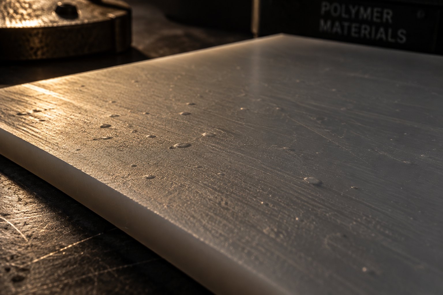
Surface defects are the first thing a customer sees — and the fastest way to lose a sale. A sheet can hit every gauge target perfectly, yet a subtle texture, a scattering of gels, or a persistent line running the full length of the roll will send it straight to scrap. What makes surface problems especially frustrating is that they look similar to each other at first glance. An orange peel defect can be mistaken for haze. A gel can look like a contaminant speck. A die line can mimic a chill roll scratch. Sorting these apart demands a clear understanding of how each one forms — and where along the line it originates.
Orange Peel Defect and Melt Fracture on Sheet Surfaces
If you have ever run your fingertips across a sheet and felt a fine, bumpy texture resembling citrus skin, you have encountered the orange peel defect. This is one of the most common surface issues in flat sheet production, and it typically stems from one of two mechanisms: melt fracture at the die lip or poor surface replication on the chill roll.
Melt fracture occurs when the polymer experiences excessive shear stress as it flows through the narrow die lip gap. The melt alternately sticks to and slips from the metal surface — a slip-stick phenomenon that creates pressure pulsations transmitted through the extrudate as it exits. In its mildest form, this shows up as a loss of surface gloss. More severe cases produce the characteristic orange peel coating defect pattern that is immediately visible across the sheet width.
The second mechanism is simpler: if melt temperature is too low, the polymer cannot fully replicate the smooth chill roll surface. Instead of conforming to the polished roll, it freezes with micro-scale roughness intact. This version of the orange peel defect is especially common in semi-crystalline resins like PP, where rapid crystallization at the surface locks in texture before the roll can smooth it out.
It is important to differentiate orange peel from two look-alikes. Sharkskin produces a more regular, fine-ridged pattern oriented in the cross direction — caused specifically by extensional stress at the die exit rather than slip-stick friction. Matte haze, on the other hand, is a uniform loss of clarity without any tactile roughness, usually tied to crystallinity or moisture rather than mechanical surface distortion.
Corrective steps for orange peel depend on its cause:
- Increase melt temperature — Reducing viscosity lowers shear stress at the die lip. On a pp extruder, raising the die zone by 5-10 degrees Celsius is often enough to eliminate mild melt fracture.
- Reduce line speed — Lower throughput means lower shear rates, though this trades off against productivity.
- Widen the die lip gap — A larger gap reduces shear stress directly, but it may limit your ability to draw down thin-gauge sheet and can alter physical properties.
- Polish the die lip land — A roughened or corroded land surface amplifies the slip-stick effect. Regular polishing prevents chronic melt fracture.
The fix also varies by resin family. Amorphous polymers like PS and ABS respond well to melt temperature increases because they do not crystallize — higher temperature simply improves flow without introducing haze. Semi-crystalline resins like PP and PET require a more careful balance: raising melt temperature helps eliminate orange peel, but excessive heat can degrade the polymer or shift crystallinity in ways that affect downstream thermoforming performance.
Die Lines, Gels, and Contamination Troubleshooting
Die lines are machine-direction streaks that run continuously along the sheet. They stand out most under oblique lighting and are among the easiest defects to trace because each line maps directly to a specific location on the die lip. Three common causes dominate:
- Lip damage — A nick, scratch, or dent on the die lip land creates a permanent flow disturbance. Even a mark too small to see without magnification can produce a visible streak on the sheet.
- Drool buildup — Degraded polymer gradually accumulates at the die exit, forming a ridge that deflects the melt stream. Drool tends to worsen over a production run and may temporarily disappear after cleaning, only to return hours later.
- Improper die bolt adjustment — An over-tightened bolt pinches the lip locally, restricting flow and creating a thin streak bordered by slightly thicker zones.
Gels are a different challenge entirely. They appear as small, raised spots — sometimes clear, sometimes discolored — scattered across the sheet surface. The critical first step is identifying what type of gel you are dealing with, because the corrective action differs sharply for each.
Gel identification generally points to one of three categories:
- Crosslinked gels — Formed when the polymer chains bond excessively due to high heat exposure, high shear, or long residence time. These gels feel hard and do not melt when reheated. They originate from the resin itself or from degraded material in stagnant zones.
- Unmelt gels — Unmelted pellet fragments that passed through the screw without fully plasticating. These are softer, often translucent, and point to insufficient melting energy — a worn screw with reduced compression, low barrel temperatures, or excessive throughput for the screw design.
- Degradation gels — Darkened, sometimes carbonized particles generated at hang-up points inside the barrel, adapter, screen changer, or die where polymer stagnates and overheats. These appear as brown or black specks surrounded by a gel-like halo.
To isolate the source, work backward through the line. Collect a sample of extrudate directly at the die exit — if gels are present, the problem is upstream of the die. Next, collect a purge sample from the adapter before the die — if gels vanish, the die internals are the culprit. Continue this zone-by-zone elimination through the screen pack and back to the barrel. If gels persist even when extruding virgin resin with a fresh screen pack, the screw or barrel surfaces are likely damaged and harboring degraded material.
Black specks deserve special attention because they alarm customers instantly. They are essentially severe degradation gels — carbonized polymer fragments that break loose from dead spots during production or, more commonly, at start-up after a shutdown period. Consistent black specks that appear at regular intervals suggest a specific hang-up point with a predictable accumulation-and-release cycle. Random black specks that appear only at start-up point to carbonized material trapped in the die, adapter, or screen changer during the previous shutdown.
Surface haze rounds out the most common complaint list. Unlike orange peel, haze has no tactile texture — the sheet feels smooth but lacks clarity. In amorphous resins, haze usually indicates moisture contamination or surface micro-roughness from a damaged chill roll. In semi-crystalline resins like PP, it is often a crystallinity issue controlled by chill roll temperature.
| Defect | Symptom | Primary Cause | Corrective Action |
|---|---|---|---|
| Orange Peel | Bumpy, citrus-skin texture visible across sheet surface | Melt fracture from excessive die lip shear stress; poor chill roll surface replication | Increase melt temperature; widen die lip gap; reduce line speed; polish die lip land |
| Die Lines | Continuous machine-direction streaks, fixed in CD position | Lip damage, drool buildup at die exit, or over-tightened die bolt pinching flow | Inspect and polish lip land; clean die exit; re-map die bolt adjustments incrementally |
| Gels | Small raised spots — clear, translucent, or discolored — scattered on surface | Crosslinked polymer, unmelt fragments, or degradation from hang-up points | Identify gel type; isolate source zone; adjust melt temperature, screen pack, or screw condition |
| Black Specks | Dark carbonized particles, often concentrated at start-up or appearing periodically | Carbonized polymer from stagnant zones in die, adapter, or barrel dead spots | Improve purging protocol; eliminate dead spots; follow proper heat soak and start-up sequencing |
| Surface Haze | Uniform loss of clarity without tactile roughness; sheet feels smooth but looks cloudy | Moisture in resin; excessive crystallinity from high chill roll temperature; micro-roughness on chill roll surface | Verify resin drying; lower chill roll temperature for semi-crystalline resins; inspect and re-polish chill roll |
One preventive practice that pays for itself repeatedly — yet rarely gets enough attention — is scheduled die lip maintenance. The die lip land is the final surface the polymer touches, and its condition directly controls surface quality. A polishing schedule based on production hours, not just visible defect occurrence, keeps melt fracture and drool problems from developing in the first place. For high-gloss applications, many plants polish the lip land every 40 to 80 hours of production using fine diamond compound. Cleaning the die exit face to remove drool buildup should happen even more frequently — every shift in some operations. Pairing this with regular inspection under magnification catches nicks and corrosion pits before they generate persistent die lines.
Surface defects tell you a great deal about what is happening inside your process, but they only represent one dimension of sheet quality. Thickness uniformity and flatness — the structural characteristics that determine whether a sheet performs in its end-use application — involve an entirely different set of variables and trade-offs that can conflict directly with the fixes applied to surface problems.
Controlling Gauge Variation and Flatness Across the Sheet Width
Here is the daily dilemma every extrusion sheet operator faces: you finally dial in a perfect thickness profile across the full width, and the sheet starts curling off the chill roll like a potato chip. You fix the curl by adjusting chill roll temperatures, and suddenly the gauge profile drifts out of spec. Thickness uniformity and flatness are two sides of the same coin — and the tools you use to control one can easily destabilize the other. Mastering this interplay separates experienced operators from those stuck in an endless loop of chasing one problem into the next.
Die Bolt Mapping and Cross-Direction Gauge Control
Die bolt adjustment is the primary tool for controlling local flow across the sheet width. Each bolt applies pressure to a small section of the flexible die lip, opening or closing the gap to allow more or less polymer through. Tightening a bolt reduces the gap and thins the sheet at that position; loosening it does the opposite. Simple in concept — but deceptively tricky in practice.
The key to effective die bolt adjustment is a systematic mapping approach rather than random tweaking. Start by measuring sheet thickness at consistent cross-direction (CD) positions. Many plants use a handheld micrometer at fixed intervals — every 50 mm or 100 mm across the width — while automated lines rely on scanning beta-gauge or X-ray systems that continuously profile the sheet. Record the measurements and correlate each thick or thin band to its corresponding die bolt zone. Most dies have bolt spacing between 25 mm and 50 mm, so a thick band centered at 300 mm from the operator side maps directly to bolts in that region.
With the map in hand, make incremental adjustments — typically one-eighth to one-quarter turn at a time. This is where patience becomes critical. After each adjustment, the die lip must reach thermal equilibrium before the effect fully shows on the sheet. Depending on the die mass and operating temperature, this can take 10 to 20 minutes. Operators who make a second adjustment before the first one stabilizes end up over-correcting, which creates new thick and thin bands that require yet another round of changes. The result is a frustrating oscillation that never converges.
The most common die bolt mistake is impatience — making a second correction before the first one has reached thermal equilibrium.
Automatic die bolt systems take the human timing problem out of the equation. These systems use continuous thickness data from a scanning gauge, compare it to a target profile, and send motorized adjustments to individual bolts through a closed-loop controller. The best systems incorporate dwell-time logic that prevents over-correction by waiting for thermal stabilization between moves. However, automatic systems are only as good as their gauge input — a miscalibrated thickness sensor or a gauge head contaminated with polymer residue will drive the bolts to correct for errors that do not actually exist on the sheet. Regular gauge calibration and cleaning are essential prerequisites for reliable automatic profile control.
One subtlety that trips up even experienced operators: die bolt adjustments change more than just thickness. Each bolt alteration modifies the local flow velocity exiting the die. Faster-flowing zones stretch more on the chill roll, slower zones stretch less — and that velocity difference introduces internal stress patterns that manifest as flatness defects downstream.
Flatness, Curl, and Bow — When Gauge Fixes Create New Problems
Imagine you have just corrected a persistent thick band on the operator side by tightening three die bolts. The gauge profile looks perfect. But twenty minutes later, the sheet begins curling toward that same side. What happened? By restricting flow at those bolts, you reduced the local flow velocity, which changed how the polymer stretches between the die and the chill roll. The speed differential between the corrected zone and the rest of the sheet creates uneven molecular orientation — and uneven orientation means uneven shrinkage, which shows up as curl.
This gauge-flatness interplay is the single most under-discussed challenge in sheet extrusion troubleshooting. Adjusting for one metric often disrupts the other, and operators need to understand the mechanism to find the right balance rather than chasing corrections in circles.
Differential cooling is another major contributor to flatness problems. In a typical chill roll stack, one side of the sheet contacts the primary roll first and cools rapidly, while the opposite side remains exposed to air briefly before contacting the second roll. That asymmetric cooling rate creates a temperature gradient through the sheet thickness, which locks in different levels of molecular relaxation on each side. When the sheet reaches room temperature, the two sides shrink by different amounts — and the sheet curls toward the side that cooled last because that side retains more residual stress.
Corrective approaches for flatness defects target the root cause of stress imbalance:
- Balance chill roll temperatures top and bottom — Matching the cooling rate on both sheet surfaces reduces the through-thickness stress differential. On some lines, running the secondary roll slightly cooler than the primary roll compensates for the extra air-side cooling time.
- Adjust the air gap before chill roll contact — The distance between the die exit and the first chill roll determines how long the melt curtain is exposed to ambient air. A shorter air gap minimizes one-sided air cooling and reduces curl tendency, but it also limits draw-down ratio.
- Ensure uniform nip pressure — Uneven pressure across the nip roll pushes the sheet against the chill roll more firmly in some zones than others, creating localized cooling differences that produce cross-width flatness variation.
Each flatness defect type has its own signature pattern and distinct set of causes. Recognizing which one you are dealing with immediately narrows the corrective path:
- Curl — The sheet curves along its width, forming a C-shape in cross section. Causes include unequal cooling between top and bottom surfaces, asymmetric molecular orientation from uneven die lip flow, or moisture absorption on one side during storage. Corrective action: balance chill roll temperatures, equalize air gap exposure, and verify uniform nip roll pressure across the full width.
- Bow — The sheet arcs along the machine direction, curving upward or downward like the hull of a boat. Causes include non-uniform tension across the sheet width at the winder, uneven MD orientation from a skewed die lip gap, or temperature gradients in the machine direction along the chill roll surface. Corrective action: verify winder tension uniformity, check die lip gap consistency from operator side to drive side, and inspect chill roll coolant circulation for blocked channels.
- Twist — The sheet spirals along its length so that opposite corners lift in different directions. Causes include misaligned chill rolls or nip rolls that apply uneven pressure diagonally, a die that is not level, or non-uniform barrel temperatures creating a melt viscosity gradient from one side of the die to the other. Corrective action: check mechanical alignment of all rolls, level the die, and verify that barrel temperature zones on both sides of the extruder match.
- Edge wave — The sheet edges ripple or buckle while the center remains flat. Causes include edges flowing faster than the center due to die lip over-opening at the edges, excessive edge cooling from ambient air exposure, or edge trim slitter tension pulling unevenly. Corrective action: tighten die bolts at the edges to restrict flow, install edge shields to reduce air cooling, and verify that edge trim systems do not apply lateral pulling forces to the main sheet.
A practical tip that saves time: when a flatness defect first appears, resist the urge to adjust die bolts immediately. Instead, check the downstream equipment first. Verify chill roll temperatures with a contact pyrometer at multiple points across the roll face. Confirm that nip roll pressure is uniform by checking the air cylinder gauges on both sides. Inspect the winder tension setting — a slight increase in brake pressure on one side can introduce bow or twist that looks exactly like a die problem. Only after ruling out these downstream factors should you begin adjusting the die.
The interaction between gauge control and flatness also highlights why the same extrusion sheet recipe can behave differently across resin types. A PP sheet that runs flat at a given die bolt setting may curl when you switch to PET, because the two resins have fundamentally different crystallization behavior and shrinkage characteristics. That resin-specific dimension adds yet another layer to the diagnostic puzzle — and demands its own set of troubleshooting strategies tailored to each polymer family.
Material-Specific Troubleshooting Paths for PP, PET, PS, and More
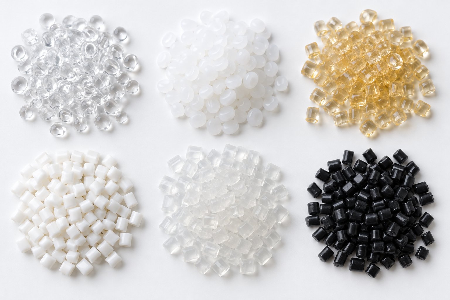
A hazy sheet means one thing on a polypropylene line and something entirely different on a PET line. The defect looks the same to the naked eye, but the root cause, the diagnostic path, and the corrective action diverge sharply depending on the resin you are running. This is where generic troubleshooting guides fall short — they list symptoms and fixes without accounting for the polymer chemistry that drives the defect. If you want to solve problems faster, you need material-specific playbooks that match your resin family to the right diagnosis.
Troubleshooting PP and Polypropylene Sheet Extrusion
Polypropylene is a semi-crystalline polymer, and that single characteristic is responsible for the majority of PP-specific defects. When PP cools, it forms organized molecular structures called spherulites. If those spherulites grow large enough to exceed the wavelength of visible light, they scatter light and produce a hazy, translucent appearance — even in sheet made from perfectly clean virgin resin. This is not contamination. It is physics.
The chill roll is your primary tool for managing PP crystallinity. Rapid quenching on a cold roll suppresses spherulite growth, yielding smaller crystals and better clarity. Set the chill roll too warm, though, and crystallization slows enough for large spherulites to form — producing haze that no amount of barrel temperature adjustment will fix. For random copolymer PP grades used in clear packaging, the processing window for achieving good clarity is remarkably narrow, often requiring chill roll temperatures between 15 degrees C and 30 degrees C depending on sheet gauge and line speed.
Clarifying agents offer another path to clarity. These additives increase the nucleation rate throughout the polymer, packing more — but smaller — crystals into the same space. The result is crystal structures too small to scatter visible light, producing sheet that rivals the transparency of amorphous resins. If you are running clarified PP and still seeing haze, your chill roll temperature is likely too high, allowing spherulite growth that overwhelms even the clarifier's effectiveness.
Beyond clarity, PP's low melt strength creates unique mechanical challenges. In heavy-gauge pp sheet extrusion, the melt curtain sags under its own weight between the die exit and the chill roll. This sag varies across the sheet width — thicker center sections sag more than the edges — introducing gauge variation that the die bolts alone cannot correct. Reducing the air gap distance and increasing line speed can mitigate sag, but both adjustments interact with cooling and crystallization behavior. In thin-gauge production, the same low melt strength manifests as draw resonance — periodic thickness oscillations in the machine direction caused by the melt curtain alternately stretching and relaxing as it is pulled onto the chill roll.
Regrind management is another PP-specific concern. Every time polypropylene passes through the extruder, the polymer chains break down slightly, lowering the melt flow index (MFI). A small percentage of regrind — typically up to 20% — blends without noticeable quality impact. Push that ratio higher and the accumulated MFI shift produces a melt with different viscosity characteristics than the virgin material, leading to gauge instability, reduced impact strength, and a narrower processing window. Track regrind ratios carefully, and if defects appear after increasing the regrind percentage, test the blended MFI against your baseline before changing process parameters.
PET, PS, ABS, and HDPE Troubleshooting Differences
PET demands respect for moisture in a way no other common sheet resin does. This polymer is hygroscopic — it absorbs water from the surrounding air — and even small amounts of residual moisture cause hydrolytic degradation during melting. The consequences are severe: intrinsic viscosity (IV) drops, reducing the molecular weight and mechanical properties of the sheet. Visually, you will see haze, bubbles, and poor surface gloss. In thermoforming applications, IV-degraded PET sheet tears or thins unevenly during forming, creating reject parts that cannot be traced to any obvious process parameter.
Proper drying is non-negotiable. PET pellets or flake must be dried to below 50 ppm moisture content before entering the extruder. The standard protocol uses a desiccant dryer operating at 160 degrees C to 175 degrees C for four to six hours, with a supply air dew point below minus 40 degrees C. Vacuum dryers offer an alternative path to the same target. Shortcuts here — reducing drying time, running at lower temperatures, or neglecting dew point monitoring — will produce defective sheet every time. As PET processing guides consistently emphasize, moisture control is the single most critical factor in PET sheet quality.
Crystallinity management in PET follows different rules than PP. For thermoforming-ready PET sheet, you want the sheet to remain largely amorphous — clear and flexible enough to stretch into a mold. Excessive crystallization during extrusion makes the sheet brittle, hazy, and difficult to thermoform. The key is rapid cooling on the chill roll, typically set between 20 degrees C and 40 degrees C, combined with a short air gap to minimize crystallization time before quenching. If your PET sheet arrives at the thermoformer with visible whitening or stiffness, the cooling rate during the sheet extrusion process was too slow.
Polystyrene (PS) brings its own set of headaches. As an amorphous resin, PS does not crystallize, so haze is rarely a concern — but stress-whitening is. When PS sheet is bent, trimmed, or thermoformed, the molecular chains under stress can craze at the microscopic level, scattering light and producing a whitened appearance along fold lines or trim edges. Reducing internal stress through optimized chill roll temperatures and lower winder tension minimizes this tendency. Brittleness in PS often traces back to excessive molecular orientation locked in during cooling — especially when running thin-gauge sheet at high line speeds.
ABS (acrylonitrile butadiene styrene) is a multi-phase polymer, and that layered structure makes it prone to delamination under certain conditions. If melt temperature is too low or shear is excessive, the butadiene rubber phase can separate from the styrene-acrylonitrile matrix, producing a peeling or flaking surface that looks like a coating failure. Gloss variation in ABS sheet typically ties back to inconsistent melt temperature or uneven chill roll contact — the rubber phase scatters light differently depending on how it is distributed at the surface. Keeping melt temperatures uniform and ensuring full chill roll wrap are the primary corrective tools.
HDPE occupies the opposite end of the flexibility spectrum. This semi-crystalline resin is tough and chemical-resistant, but excessive molecular orientation during extrusion introduces environmental stress cracking vulnerability — the sheet performs well initially but fails prematurely when exposed to chemicals or sustained loads in its end-use application. Reducing draw-down ratio, lowering line speed, and increasing melt temperature all help relax orientation. If stress cracking complaints come back from the field, check whether line speed or draw-down ratios were pushed beyond the resin supplier's recommended range.
To give you a practical starting point when setting up a new resin or diagnosing a problem on an unfamiliar material, the following table summarizes recommended initial process parameters by resin family. These are starting values — always consult your resin supplier's datasheet for grade-specific targets.
| Resin | Barrel Zones (degrees C) | Die Temperature (degrees C) | Melt Temperature Target (degrees C) | Chill Roll Temperature (degrees C) |
|---|---|---|---|---|
| PP (Homopolymer) | 200 - 230 | 220 - 240 | 210 - 240 | 15 - 35 |
| PP (Random Copolymer) | 195 - 225 | 215 - 235 | 205 - 230 | 15 - 25 |
| PET | 260 - 290 | 270 - 300 | 270 - 295 | 20 - 40 |
| PS (GPPS) | 180 - 230 | 200 - 230 | 200 - 230 | 40 - 70 |
| ABS | 200 - 240 | 210 - 240 | 210 - 245 | 50 - 80 |
| HDPE | 180 - 220 | 200 - 230 | 200 - 230 | 40 - 70 |
Notice the stark differences. PET runs 60 to 70 degrees C hotter than PP in the barrel, yet its chill roll temperature is similar — both resins demand aggressive quenching, but for entirely different crystallinity-related reasons. PS and ABS tolerate warmer chill rolls because they are amorphous and do not develop crystalline haze, but they are more sensitive to residual stress from rapid cooling. HDPE needs moderate temperatures everywhere, with the emphasis on avoiding excessive orientation rather than managing crystallinity.
These resin-specific behaviors also explain why a pp pe board extrusion line running layered PP/PE structures must balance two different thermal profiles simultaneously — the PP layer wants aggressive chill roll quenching for clarity while the PE layer tolerates warmer rolls but is more sensitive to orientation stress. The compromises required in multi-material setups highlight why material knowledge is just as important as machine knowledge when diagnosing sheet defects.
Knowing how each resin behaves under specific conditions is essential, but the fastest path to catching a problem before it reaches the sheet surface is learning to read the signals your extruder instruments are already generating — melt pressure trends, motor load shifts, and temperature fluctuations that predict defects minutes before they become visible.
Reading Melt Quality Indicators to Predict Sheet Defects
Your extruder control panel is not just a monitoring display — it is a diagnostic instrument capable of warning you about plastic sheet extrusion defects before they ever reach the chill roll. The challenge is that most operators glance at melt pressure, barrel temperatures, and motor amps to confirm they are "in range," then look away. That habit misses the real value: the trends, fluctuations, and relationships between those numbers tell a story about melt quality that the sheet surface will only reveal minutes later. Learning to read that story transforms reactive troubleshooting into proactive intervention.
Melt Pressure and Temperature as Early Warning Signals
Melt pressure — measured at the adapter between the barrel and the die — is the single most informative data point on a sheet extrusion line. It integrates the effects of screw feeding consistency, melting uniformity, screen pack condition, and die restriction into one continuously updated number. When everything is running well, melt pressure holds steady with variation under roughly 50 PSI during stable operation. The absolute value depends on your die geometry, resin viscosity, and screen pack configuration, but consistency is what matters most for extrusion melt pressure troubleshooting.
Fluctuating melt pressure tells you something has changed upstream. Rhythmic cycling — pressure rising and falling at regular intervals — points to inconsistent screw feeding. Common culprits include pellet bridging in the hopper throat, starve feeding from a blocked or inconsistent gravimetric feeder, or worn screw flights that have lost pumping efficiency and allow polymer to slip backward over the flights. On a pp ps sheet extrusion line running multi-layer structures, pressure surging in even one extruder creates interfacial instability between layers that shows up as waviness or gauge banding in the finished sheet.
A gradual upward drift in baseline pressure over the course of a production run — say, 50 to 100 PSI per hour — is a classic signature of screen pack blinding. Contaminants accumulate on the mesh, restricting flow and forcing the screw to push harder. The practical rule is to schedule a screen change when pressure reaches about 80% of the maximum rated value for your screen changer, rather than waiting for an alarm. Waiting too long risks a pressure spike that forces degraded material through the mesh, seeding gels and black specks into what was otherwise clean sheet.
Melt temperature measurement, on the other hand, is trickier than it appears. Most extruders use a thermocouple positioned in the adapter or transfer line, flush-mounted to the wall or inserted a few millimeters into the flow. Research by Mark Spalding at Dow has demonstrated that this standard configuration can produce significant measurement errors. The thermal conductivity of molten polymer is roughly 70 to 200 times lower than the surrounding metal, so the thermocouple junction is heavily influenced by the barrel or transfer pipe temperature rather than the actual melt temperature. In one experiment, a flush-mount thermocouple reported 198 degrees C while the actual bulk melt temperature was closer to 233 degrees C — a 35-degree error that would completely mislead any troubleshooting effort.
What does this mean practically? The melt temperature reading on your control panel is useful for trending — watching whether it rises, falls, or becomes erratic over time — but it may not accurately represent the true bulk temperature of the polymer. If you need an accurate snapshot, measure the extrudate directly at the die exit with a handheld thermocouple probe inserted into the melt stream, or use an infrared gun if downstream equipment prevents safe contact. The transfer line temperature should be set near the bulk melt temperature to minimize thermal gradients entering the die, not used as a cooling device to bring down an overheated melt.
Motor Load, Screw Speed, and Their Connection to Sheet Defects
Motor amperage — or torque, depending on your drive system — is the extruder's effort indicator. It reveals how hard the screw is working to convey, melt, and pump polymer. Like melt pressure, its absolute value matters less than its stability and its trend over time.
Consider a scenario: your pp board extrusion line has been running the same resin at the same screw speed for months. Gradually, you notice that motor amps at that constant speed have been declining — perhaps dropping 5% to 10% over several weeks. Output may have dipped slightly too, though the operator compensated by bumping screw speed up a few RPM. This pattern is a textbook signature of screw flight wear. As the clearance between the flight tips and the barrel bore increases, polymer slips backward over the worn flights instead of being pumped forward. The screw encounters less resistance, draws fewer amps, and delivers less output per revolution. The operator's instinct to increase RPM masks the problem temporarily but accelerates wear and raises melt temperature — compounding the issue.
A sudden spike in motor load tells a different story. If amps jump sharply without any change in screw speed or setpoints, look downstream for an obstruction: a partially blocked screen pack, a frozen die zone, or a contamination slug passing through the barrel. Correlating the timing of a motor load spike with the downstream appearance of gels or pressure surges often reveals a direct cause-and-effect link — the spike occurred when a chunk of unmelt or contamination hit the compression zone, and the resulting gel appeared on the sheet a few minutes later, consistent with the melt's transit time through the die.
A change in melt pressure stability is the earliest detectable sign of most sheet extrusion problems — often visible minutes before the defect appears on the sheet.
To unlock the full diagnostic value of these indicators, you need a reference point. Establish baseline values during a known-good production run — a period when the sheet meets all specifications, the screen pack is fresh, and the screw and barrel are in good condition. Record melt pressure (mean and variation range), melt temperature, motor amps, and chill roll temperatures. These baselines become your fingerprint of a healthy process.
From there, set meaningful alarm thresholds. A practical tiered approach works well:
- Advisory level — Any parameter trending 10% from baseline. This is your early-warning signal to start investigating, not to change settings.
- Warning level — A parameter reaching 15% to 20% deviation, or two parameters drifting simultaneously. At this point, plan a corrective action such as a screen change or process adjustment.
- Critical level — Any parameter exceeding 25% deviation or approaching equipment safety limits. This requires immediate action to prevent scrap, equipment damage, or a safety hazard.
Trending this data over weeks and months — not just glancing at it shift by shift — reveals gradual degradation patterns that shift-level observations miss entirely. A slow, steady decline in output per RPM over three months tells you the screw is wearing before any defect becomes visible on the sheet. A heater duty cycle in one barrel zone creeping from 55% toward 90% warns of an impending heater band failure days or weeks before it happens. These are the kinds of signals that separate plants running scheduled maintenance from plants running emergency repairs at 2 AM.
Of course, instrument readings only help during stable production. The most defect-prone moments in any extrusion operation — start-ups, shutdowns, and material transitions — demand their own set of procedures and diagnostic logic that go well beyond steady-state monitoring.

Start-Up, Shutdown, and Transition Troubleshooting Procedures
Steady-state production is the easy part. The moments that generate the most scrap, the most customer complaints, and the most frustration are the transitions — starting the line after a shutdown, switching from one color or resin to another, and shutting down without setting tomorrow's start-up up for failure. These phases are responsible for a disproportionate share of black specks, color streaking, and degradation defects, yet they rarely receive the procedural discipline they deserve.
Start-Up Procedures That Prevent Black Specks and Degradation
Every black speck that appears during the first thirty minutes of production was created during the previous shutdown. When a line stops, molten polymer remains inside the barrel, adapter, screen changer, and die. As temperatures hold — or drop unevenly — that stagnant material degrades and carbonizes in dead spots: screw root corners, adapter bends, feedblock channels, and die manifold edges. At the next start-up, the screw pushes fresh resin through these zones and dislodges carbonized fragments directly into the melt stream.
A disciplined extruder start-up procedure breaks this cycle. The critical principle is heat soak sequencing — bring the die and adapter up to operating temperature before starting the screw. A cold die acts as a plug, causing dangerous pressure spikes when the screw begins pushing melt forward. Heating the die first ensures the flow path is open and that frozen polymer in the die channels softens enough to exit cleanly rather than breaking loose in chunks.
Once all zones reach setpoint and have soaked for at least 20 to 30 minutes, start the screw at low RPM — typically 10% to 15% of normal production speed. This gentle ramp-up allows polymer to flush through stagnant zones without generating the high shear forces that break carbonized deposits into fine particles scattered throughout the melt. Increase speed gradually, checking the extrudate visually at the die exit for specks, discoloration, and gels before engaging the chill roll stack and downstream equipment.
Purging compounds accelerate this cleaning phase significantly. Rather than wasting production resin to push out degraded material, a dedicated mechanical purging compound forms a dense, thermoelastic mass inside the screw flights that physically scrubs barrel surfaces and displaces contamination far more effectively than standard resin. The key to extrusion purging best practices is choosing the right compound for your temperature range and running it at moderate screw speed — too fast and the purge material passes through without sufficient cleaning contact, too slow and it lacks the mechanical action needed to dislodge stubborn carbon deposits. Continue purging until the extrudate runs visually clean, then transition directly to your production material.
Material Transitions and Color Change Best Practices
Color streaking during a plastic extrusion color change is almost never a material defect — it is a process problem rooted in how polymer hides inside your screw geometry. Deep-channel screws designed for high output retain more material in their flight roots, creating stagnant pockets where pigment from the previous run lingers long after the hopper has been filled with new material. Barrier screws with mixing sections clear faster because they force the melt through narrow passages that sweep residual resin along. Knowing your screw's purge behavior saves hours of trial and error during transitions.
The sequencing decision — purge with the new production material or use a dedicated purging compound — depends on the color jump and cost equation. A light-to-dark change (white to black, for instance) often works fine using the new dark resin as the purge, since residual light pigment disappears quickly into the darker background. A dark-to-light change is far more demanding; even trace amounts of dark pigment remain visible in a light sheet. In these cases, running a neutral purging compound between colors eliminates the carryover much faster than flushing with expensive light-colored production resin.
Scrap minimization during changeovers comes down to preparation. Have the new material dried and ready, blending equipment cleaned, and downstream settings pre-adjusted before you begin. Every minute of hesitation during a transition means more off-spec sheet winding onto the roll.
Seasonal and environmental factors add another layer of variability that catches many operations off guard. A line that runs perfectly in January may struggle in July — not because anything mechanical changed, but because ambient temperature rose 20 degrees C and relative humidity doubled. Higher ambient temperatures reduce cooling efficiency at the feed throat, potentially causing premature pellet softening and inconsistent feeding. Increased humidity affects hygroscopic resins like PET and nylon, degrading melt quality even when drying times remain unchanged. Adjusting dryer dew points and feed throat cooling water temperatures seasonally prevents these problems from masquerading as equipment failures.
Resin lot-to-lot variation is equally insidious. A new lot of PP with a melt flow index that has shifted by just 2 to 3 g/10 min from the previous lot — well within the resin supplier's specification — can alter viscosity enough to change your gauge profile, shift chill roll quenching behavior, and move the entire process window. Routine MFI testing of incoming resin lots catches these shifts before they reach the extruder, giving operators a chance to adjust parameters proactively rather than chasing unexpected defects.
To pull these practices together into a repeatable routine, the following checklist covers the critical first thirty minutes of any production run:
- Inspect and clean the die lip — Remove drool buildup and check for damage before heating begins.
- Heat the die and adapter first — Bring these zones to operating temperature before the barrel zones to prevent cold-die pressure spikes.
- Heat barrel zones sequentially from die end to feed end — Allow 20 to 30 minutes of soak time after all zones reach setpoint.
- Verify resin drying conditions — Confirm dew point, temperature, and residence time meet the resin datasheet requirements, especially for PET and nylon.
- Start the screw at 10% to 15% of production speed — Observe melt pressure stabilization and watch for pressure spikes that indicate cold spots or blockages.
- Purge until extrudate is visually clean — Use a dedicated purging compound for severe contamination or dark-to-light color changes; otherwise, purge with production resin.
- Inspect extrudate at the die exit before engaging chill rolls — Check for black specks, gels, discoloration, and unmelted particles by hand-pulling a sample.
- Engage chill rolls and downstream equipment at reduced line speed — Verify sheet surface quality and gauge profile before ramping to full production speed.
- Record baseline melt pressure, melt temperature, and motor amps — These values become the reference point for monitoring the rest of the production run.
- Ramp to full production speed incrementally — Increase speed in 10% to 15% steps, confirming gauge and surface quality at each stage before proceeding.
Posting this checklist near the extruder control panel gives every operator — including less experienced shift personnel — a consistent procedure that eliminates the guesswork responsible for most start-up scrap. The discipline pays for itself within a few production runs through reduced waste, fewer customer complaints about black specks, and faster transitions that recover sellable sheet sooner.
Structured start-up and transition procedures are a form of preventive action — solving problems before they occur. That same proactive philosophy, extended across the entire production cycle, relies on continuous monitoring of the process indicators discussed earlier and a clear understanding of which problems operators can fix themselves and which ones signal deeper mechanical issues requiring outside expertise.
Preventive Monitoring and Knowing When to Seek Expert Help
Fixing a defect after it shows up on the sheet is necessary — but it is also expensive. Every meter of off-spec sheet that winds onto a roll before someone spots the problem represents wasted material, wasted energy, and wasted time. The real payoff in extrusion process monitoring comes from catching problems before they produce visible defects — and that requires shifting from glancing at instrument panels to systematically tracking what those instruments are telling you over days, weeks, and months.
Preventive Process Monitoring and Baseline Tracking
The foundation of preventive maintenance plastic extrusion programs is a documented baseline — a snapshot of what every key parameter looks like when your line is running well. Pick a production run where the sheet meets all specifications, the screen pack is fresh, and the screw and barrel are in known good condition. During that run, record the following values and their normal variation ranges:
- Melt pressure — Mean value and peak-to-peak fluctuation at the adapter. A healthy line typically holds within plus or minus 50 PSI of the mean during steady-state operation.
- Melt temperature — The reading at your standard thermocouple location, along with the offset between this reading and the actual bulk melt temperature if you have verified it with an immersion probe.
- Motor amperage — Average amps at your standard screw speed. This is your pumping efficiency fingerprint.
- Output per RPM — Divide your line's throughput rate (lb/hr or kg/hr) by screw speed. This ratio is the single most sensitive indirect indicator of screw condition, as extrusion specialists have documented extensively.
- Heater duty cycles — The percentage of time each barrel zone heater stays energized. Stable operation usually puts these between 40% and 70%.
- Chill roll temperatures — Measured at multiple points across the roll face, not just at the controller readout.
Document these values and post them where operators can reference them. They become the yardstick against which every future shift is measured.
With baselines established, set tiered alarm thresholds that distinguish between early drift and urgent action. A practical three-tier system works well for most sheet lines:
| Alert Level | Trigger Condition | Operator Response |
|---|---|---|
| Advisory (Yellow) | Any parameter trending 10% from baseline; heater duty cycle in any zone exceeding 85%; output per RPM declining more than 5% | Begin investigating — check material consistency, screen pack differential, and downstream settings. Do not change process parameters yet. |
| Warning (Orange) | Any parameter 15%-20% from baseline; two or more parameters drifting simultaneously; melt pressure oscillation amplitude doubling | Plan corrective action — schedule screen change, verify heater band function, or prepare for a controlled shutdown to inspect screw condition. |
| Critical (Red) | Any parameter exceeding 25% deviation; melt pressure approaching equipment safety rating; motor amps at overload threshold | Take immediate action — reduce screw speed, initiate controlled shutdown if necessary, and isolate the root cause before resuming production. |
Screen pack pressure differential deserves its own monitoring routine because it doubles as a maintenance scheduling tool. Track the rate of pressure rise — not just the absolute value — across each production run. A clean screen pack loading at 50 to 100 PSI per hour indicates normal contaminant levels in the resin. If that rate suddenly doubles on a new resin lot, you have an incoming material quality issue worth investigating before it fills the screen and forces degraded material through the mesh. Scheduling screen changes when differential pressure reaches 80% of the maximum rated value — rather than waiting for an alarm — keeps quality consistent and avoids the emergency scramble of a fully blocked screen.
The real power of trending emerges over longer timeframes. A melt pressure mean that holds rock-steady from shift to shift but slowly drops 8% over three months reveals progressive screw wear — the flights are losing pumping efficiency so gradually that no single day's data looks abnormal. A barrel zone heater duty cycle that creeps from 55% to 82% over six weeks warns of an impending heater band failure days before the zone temperature starts missing its setpoint. These slow-moving signals are invisible to operators who only check today's numbers against today's setpoints. They become obvious when you plot the data on a weekly or monthly trend chart.
Knowing When to Call for Equipment Support
Not every problem can be solved by adjusting temperatures, speeds, or die bolts. Some symptoms point to mechanical degradation that no process tweak can compensate for — and continuing to adjust parameters around a worn component only delays the inevitable while producing marginal sheet in the meantime. Recognizing extruder screw barrel wear signs early enough to plan a repair rather than suffer an emergency breakdown is one of the highest-value skills in sheet extrusion.
The following classification helps operators decide whether to keep troubleshooting at the control panel or escalate to a mechanical inspection:
Solvable by process adjustment:
- Gauge variation that responds to die bolt correction and stabilizes after thermal equilibrium
- Surface haze that clears when chill roll temperature is adjusted within the resin's recommended range
- Melt pressure fluctuation that resolves after a screen change or hopper feed correction
- Color streaking during a transition that clears with proper purging technique
- Curl or flatness defects that respond to chill roll temperature balancing or nip pressure adjustment
- Intermittent gels that disappear after switching to a new resin lot or reducing regrind percentage
Requires mechanical inspection:
- Declining output at constant screw speed — When you need 15% to 20% more RPM to maintain the same throughput you achieved six months ago, the screw flights or barrel bore are worn beyond the point of process compensation. Industry guidelines suggest screw replacement when output per RPM drops below 85% of the new-screw baseline, or when flight clearance exceeds 0.010 inches per side on a standard single-screw extruder.
- Persistent melt temperature non-uniformity — If one barrel zone consistently overshoots or undershoots despite correct controller settings, suspect a failed heater band, a degraded thermocouple sending erratic signals, or barrel scoring that has changed the heat transfer profile in that section.
- Increasing drive motor amps without process changes — Rising amperage at constant screw speed and unchanged material indicates mechanical drag — bearing wear in the gearbox, misalignment between the drive and the barrel, or contamination buildup inside the barrel that is physically resisting screw rotation.
- Recurring gels that persist after purging and screen changes — When gels keep appearing even with fresh screens, new resin, and thorough purging, the source is almost certainly barrel wall degradation or screw surface pitting that harbors degraded polymer in microscopic crevices no purge compound can reach.
- Progressive melt temperature rise at constant settings — A worn screw generates more shear heat as polymer slips over degraded flights, pushing discharge temperatures above barrel setpoints. If melt temperature runs more than 15 degrees C above the expected value, screw condition is the likely cause.
When these mechanical symptoms surface, the most productive response is to schedule a screw pull and measurement rather than continue compensating with process adjustments that mask the wear and accelerate it simultaneously. Measure flight outside diameter clearance, metering section depth, and barrier flight condition against the original specifications. For barrel inspection, gauge the bore diameter at multiple points along its length — particularly in the compression and metering zones where wear concentrates.
This is where partnering with a screw and barrel specialist becomes a practical necessity rather than just a good idea. When worn flights, barrel wear, or screw damage is confirmed, a supplier like NANHAIYA can provide targeted support for screw barrel assessment and replacement — addressing the output instability, melt-quality problems, and pressure fluctuations that worn components produce. Having a trusted supplier relationship in place before a critical failure occurs means replacement screws can be specified and ordered based on your measured wear data, converting what would be an emergency shutdown into a planned maintenance event with minimal production disruption.
The broader principle is straightforward: process adjustments are your first line of defense, and they solve the majority of day-to-day sheet quality problems. But when the data trends and symptom patterns point to hardware degradation, the fastest path back to consistent production is acknowledging the mechanical root cause and acting on it — not spending another month adjusting die bolts around a screw that is losing 15% of its pumping efficiency.
Single-layer sheet troubleshooting, challenging as it is, at least involves one melt stream through one flow path. Multi-layer co-extrusion adds an entirely new dimension of complexity — multiple extruders, interfacial interactions, and layer distribution problems that demand their own diagnostic framework.
Co-Extrusion Sheet Troubleshooting for Multi-Layer Production
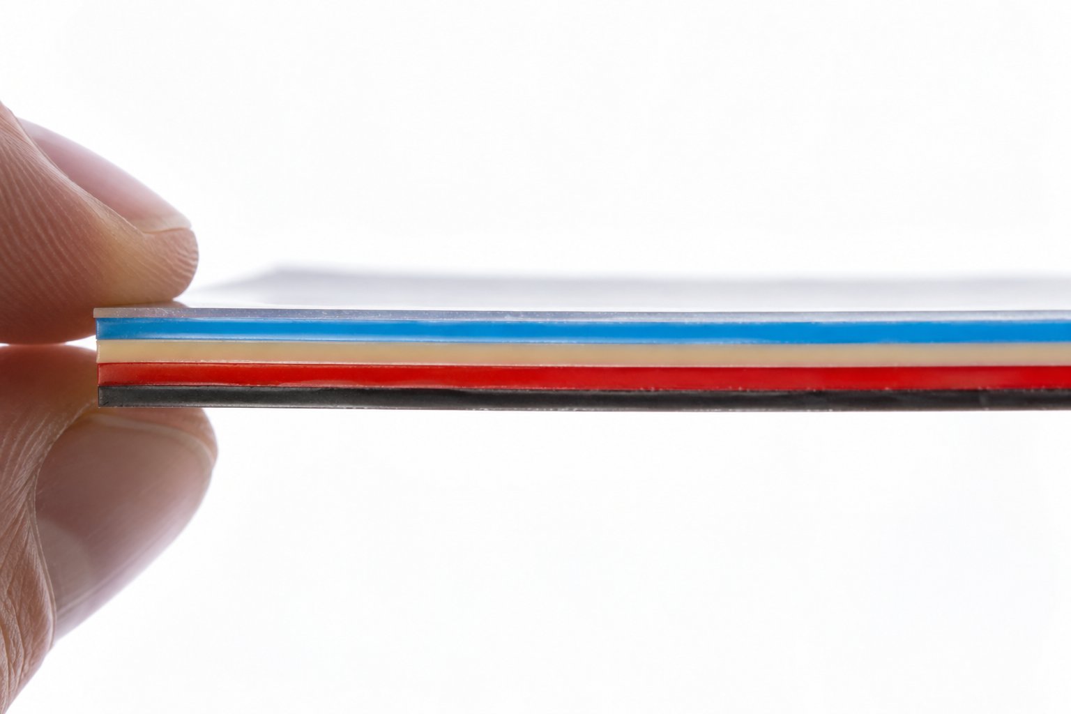
When two or more extruders feed a single die, every variable multiplies. Each melt stream brings its own temperature, viscosity, and flow rate — and the interface where those streams meet becomes a new failure point that does not exist in single-layer production. Co-extrusion sheet problems are notoriously difficult to diagnose because a defect visible on the finished sheet may originate inside the die at a layer boundary no one can see directly. Yet multi layer sheet extrusion is the standard process for barrier packaging, cap-layer structures, recycled-core products, and countless other applications where combining materials in a single pass delivers performance no monolayer sheet can match.
Two die system types dominate co-extrusion: feedblock dies, which combine melt streams in an adapter before a conventional coat-hanger die, and multi-manifold dies, which distribute each layer separately and join them near the die exit. Feedblock systems offer flexibility and lower cost but demand that all layers have similar melt temperatures and viscosities. Multi-manifold dies tolerate larger rheological differences but are more complex and expensive. Knowing which system your line uses is the first step in diagnosing co-extrusion defects, because the root causes — and corrective actions — differ between the two.
Layer Adhesion and Interfacial Instability in Co-Extruded Sheet
Delamination — layers peeling apart during trimming, thermoforming, or end use — is the most immediately damaging co-extrusion defect. Three root causes account for the vast majority of cases:
- Incompatible melt temperatures between layers — If one layer arrives at the interface significantly hotter or cooler than its neighbor, the temperature differential limits molecular interaction at the boundary. Adhesion depends on intimate contact and, for compatible polymers, interdiffusion of molecular chains across the interface. A temperature mismatch reduces the mobility needed for those chains to interpenetrate. Research on PP-based co-extruded sheets has shown that both temperature and contact time within the die directly govern interdiffusion rates and resulting peel resistance.
- Insufficient tie-layer thickness — When bonding incompatible polymers such as a polyolefin to a barrier resin like EVOH, a tie layer containing reactive functional groups forms the chemical bridge between them. If that layer thins out — especially at the sheet edges where encapsulation effects can squeeze it — delamination occurs locally even though the center of the sheet bonds well.
- Melt viscosity mismatch at the interface — Large viscosity differences create shear stress discontinuities at the layer boundary. The resulting velocity gradient can inhibit chain entanglement and reduce bond strength, particularly in feedblock systems where the combined flow travels a longer path.
Interfacial instabilities are a separate but related category. Imagine peeling apart a co-extruded sample and seeing a zig-zag or wavy pattern at the layer boundary instead of a smooth, flat interface. These distortions are flow instabilities that develop inside the die, and they fall into two main types. Low-frequency wave-type instabilities produce gentle undulations at the interface — visible as periodic thickness fluctuations in each layer. High-frequency zig-zag instabilities create sharp, chevron-shaped distortions that can cause local mixing between layers. In situ detection studies using optical coherence tomography have confirmed that these instabilities correlate directly with the interface position relative to the die wall: shifting the interface away from the center — by increasing one layer's flow rate disproportionately — pushes the process from stable to wave-type and eventually to zig-zag instability.
The practical fix targets viscosity balance. Adjusting individual extruder melt temperatures changes each layer's viscosity independently. If the skin layer is running too hot relative to the core, its lower viscosity creates a shear imbalance at the interface that triggers waviness. Raising the core extruder temperature — or reducing the skin temperature — narrows the viscosity gap and stabilizes the interface. Adjusting individual extruder screw speeds to fine-tune the flow rate ratio provides a second lever of control. The goal is to keep the interface position near the center of the flow channel, where interfacial shear stress is lowest.
Layer Thickness Distribution and Encapsulation Problems
Encapsulation is a phenomenon unique to multi layer sheet extrusion and one of the most counterintuitive problems you will encounter. In a feedblock-style die, the lower-viscosity melt tends to migrate around the higher-viscosity melt, gradually wrapping it and pushing it away from the die walls. The thermodynamic driver is energy minimization — the system reduces its overall pressure drop by placing the less viscous material at the wall where shear rates are highest. Comprehensive coextrusion flow reviews have demonstrated that this encapsulation can progress rapidly in die geometries with significant land length, particularly in the coat-hanger distribution channel upstream of the lip.
The visible result on the finished sheet is uneven layer distribution across the width. You might measure a perfectly uniform total gauge, yet find that the barrier layer is twice as thick in the center as at the edges — or worse, entirely absent near the sheet margins. For barrier packaging, this means oxygen or moisture protection fails at the edges even though laboratory tests on center-cut samples pass. For recycled-core structures, it means the recycled layer shows through at the edges, degrading surface appearance.
Corrective approaches for encapsulation focus on matching viscosities:
- Adjust melt temperatures — Raise the temperature of the more viscous layer to bring its viscosity closer to the less viscous layer at processing shear rates. This is the fastest adjustment available.
- Feedblock profiling — Many modern feedblocks include adjustable vanes or inserts that pre-distribute each layer's thickness profile before it enters the coat-hanger die. Over-feeding the edges of the high-viscosity layer compensates for the encapsulation that occurs downstream.
- Die design considerations — Shorter land lengths reduce the distance over which encapsulation can develop. Multi-manifold dies that combine layers near the exit inherently limit this problem, which is one reason they are preferred for structures with large viscosity mismatches.
Regrind incorporation adds another complication. In multi-layer structures, regrind is typically added to the core or non-critical layer to keep costs down. But contaminated regrind — carrying traces of adhesive, barrier resin, or degraded material — can migrate to the interface during flow, seeding interfacial defects that look like delamination but are actually contamination-driven adhesion failures. If interfacial quality deteriorates after increasing regrind percentage, test the regrind stream for contaminants before assuming a process problem.
The following matrix summarizes the five most common co-extrusion defects, their visual signatures, likely root causes, and corrective actions:
| Defect Type | Visual Appearance | Likely Root Cause | Corrective Action |
|---|---|---|---|
| Delamination | Layers separate during trimming, bending, or thermoforming; peeling visible at cut edges | Incompatible melt temperatures; insufficient tie-layer thickness; excessive viscosity mismatch reducing interdiffusion | Match melt temperatures between layers; increase tie-layer flow rate; verify tie-layer resin compatibility with adjacent materials |
| Interfacial Waviness | Periodic thickness fluctuation visible in cross-section; wavy layer boundary seen under magnification or in transparent structures | Viscosity ratio imbalance driving wave-type instability; interface shifted too far from channel center; excessive overall throughput | Adjust individual extruder temperatures to match viscosities; rebalance flow rate ratios; reduce total throughput if necessary |
| Encapsulation | Uneven layer distribution across sheet width — thin or absent layers at edges with thick center; barrier or surface layer missing at margins | Lower-viscosity melt migrating around higher-viscosity melt in feedblock and die distribution channel | Match layer viscosities via temperature adjustment; use feedblock profiling vanes to over-feed edges; consider shorter die land or multi-manifold die |
| Uneven Layer Ratio | Overall gauge is on target but individual layer thicknesses vary across the width or fluctuate in the machine direction | Screw speed fluctuation in one extruder; pressure surging from inconsistent feeding; feedblock geometry not matched to current flow rates | Stabilize individual extruder feed and screw speed; verify gravimetric feeder consistency; recalibrate feedblock inserts for current operating point |
| Tie-Layer Failure | Localized delamination at specific positions — often edges or corners — while center adhesion remains strong | Tie layer thinning from encapsulation at edges; tie-layer resin degradation from excessive temperature; insufficient reactive bonding time | Increase tie-layer extruder output; reduce tie-layer melt temperature if degradation is suspected; increase die land length or reduce line speed to extend contact time |
A practical diagnostic tip for any co-extrusion defect: always cross-section the sheet and examine the layer structure under magnification before adjusting process parameters. A simple razor cut followed by inspection under a low-power microscope — or even a loupe — reveals whether the layers are uniformly distributed, whether the interface is smooth or disturbed, and whether the tie layer is present at full thickness. This five-minute examination often identifies the root cause faster than hours of guessing from the control panel. For transparent structures, holding the sheet at an angle under strong light can reveal interfacial waviness without any cutting at all.
Co-extrusion troubleshooting ultimately follows the same hierarchy used throughout this guide — material, then machine, then process — but applied independently to each extruder and then collectively to the combined flow. That layered diagnostic logic sets the stage for pulling all the threads of this article together into a single, actionable checklist operators can use on the production floor every day.
Bringing It All Together With an Actionable Diagnostic Checklist
You have walked through every station on the line, classified defects by direction, diagnosed surface problems, balanced gauge against flatness, adapted your approach to each resin family, learned to read instrument trends, tightened your start-up and transition procedures, built a preventive monitoring program, and tackled multi-layer complexity. That is a lot of ground — and the risk with any comprehensive plastic sheet extrusion guide is that operators return to the floor overwhelmed rather than equipped. The antidote is a single, structured procedure they can follow every time a defect appears, regardless of whether it is a gel on a PP monolayer or an encapsulated barrier layer on a five-layer co-extrusion.
The Root-Cause Analysis Checklist for Every Sheet Defect
The diagnostic hierarchy introduced at the start of this article — material first, then machine condition, then process parameters — is not arbitrary. It reflects the reality that material problems cannot be fixed by machine adjustments, and machine wear cannot be compensated by process tweaks indefinitely. Skipping a level wastes time and often creates secondary defects that obscure the original cause.
Here is how each section of this guide maps to that hierarchy:
| Diagnostic Level | What to Investigate | Relevant Article Sections |
|---|---|---|
| Material | Resin moisture, MFI variation, regrind ratio, contamination, lot-to-lot consistency | Material-Specific Troubleshooting Paths; Start-Up, Shutdown, and Transition Procedures |
| Machine Condition | Screw/barrel wear, heater band function, thermocouple accuracy, die lip condition, chill roll surface, screen pack state | Understanding the Complete Line; Surface Defects; Preventive Monitoring and Knowing When to Seek Expert Help |
| Process Parameters | Barrel zone temperatures, screw speed, die bolt profile, chill roll temperature, winder tension, line speed | Gauge Variation and Flatness; Reading Melt Quality Indicators; Co-Extrusion Troubleshooting |
When a defect appears, resist the urge to reach for the nearest process knob. Instead, work through the following extrusion defect root cause analysis procedure — a condensed 10-step sequence designed to be printed and posted near the extruder control panel:
- Name the defect and classify its direction — Is it cross-direction (gauge bands, gloss variation across the width), machine-direction (periodic surging, die lines), or random (gels, black specks, contamination)? This single classification eliminates more than half of the possible causes immediately.
- Locate where the defect first becomes visible — Walk the line from the die exit downstream. If the defect is already present at the die, the cause is upstream — barrel, screw, screen, or material. If the sheet looks good at the die but the defect appears at the chill roll, trim station, or winder, investigate downstream equipment first.
- Check the material — Verify resin moisture content, confirm the regrind ratio has not changed, inspect for visible contamination in the hopper, and compare the current lot's MFI to your baseline. Rule out material as a cause before moving on.
- Review instrument baselines — Compare current melt pressure, melt temperature, motor amps, and output per RPM against your documented baselines from a known-good run. Any parameter trending more than 10% from baseline is a lead worth following.
- Inspect the screen pack — Check differential pressure across the filter. If it has risen significantly since the last screen change, replace the screen and see whether the defect resolves before making other adjustments.
- Examine the die lip — Look for drool buildup, nicks, corrosion, or damage under magnification. Clean and polish if necessary. Map any die lines to specific bolt zones.
- Check downstream equipment — Measure chill roll temperatures at multiple points across the roll face. Verify nip roll pressure uniformity. Confirm winder tension settings match the recipe. Many defects attributed to the extruder originate here.
- Make one controlled adjustment at a time — If the investigation points to a specific process variable, change only that variable and wait for thermal equilibrium before judging the result. Document the change, the time, and the outcome.
- Verify the fix is stable — Run at least 15 to 20 minutes of production after a correction to confirm the defect does not return. Short-lived improvements that fade suggest the adjustment addressed a symptom rather than the root cause.
- Record the finding — Log the defect description, root cause identified, corrective action taken, and result in your plant troubleshooting record. This entry becomes institutional knowledge that accelerates future diagnosis.
This sheet extrusion troubleshooting checklist works for monolayer and co-extruded structures alike. For multi-layer production, apply steps three and four independently to each extruder before investigating the combined flow path and interfacial behavior.
Building Your Sheet Extrusion Troubleshooting Resources
A checklist gets you through the immediate crisis. Long-term improvement requires building two things: a plant-specific knowledge base and a network of technical partners who understand sheet-specific challenges.
The troubleshooting log mentioned in step ten is one of the most undervalued tools in any extrusion plant. Over months and years, it reveals patterns that no single operator can hold in memory. You will discover that a particular gel problem recurs every time humidity rises above a threshold, or that gauge instability follows every fourth resin lot from a specific supplier, or that black specks concentrate in the first 20 minutes after a weekend shutdown but never after an overnight stop. These patterns transform reactive firefighting into predictive problem avoidance. Keep the log simple — date, defect description, CD/MD/random classification, root cause, corrective action, and result — and make it accessible to every operator on every shift.
Equally important is establishing relationships with equipment and component suppliers before a crisis forces you to find one at 2 AM on a Saturday. Your toolkit of technical resources should include:
- Resin supplier technical support — For grade-specific processing windows, MFI specifications, and drying protocols. They can also help diagnose lot-to-lot variation issues that fall within their specification but outside your process window.
- Screw and barrel specialists — When troubleshooting reveals mechanical root causes such as output instability, pressure fluctuation, overheating, or blockage, a dedicated partner can assess wear conditions and specify replacements matched to your resin and application. NANHAIYA, for example, provides practical screw barrel support for extrusion plants, recycling operations, and processing teams dealing with these exact equipment-level issues — turning what would be an emergency shutdown into a planned maintenance event with components engineered for your specific line requirements.
- Die and downstream equipment manufacturers — For die lip refurbishment, chill roll resurfacing, and thickness gauge calibration services that keep your finishing equipment performing to specification.
- Purging compound suppliers — For material-specific purge recommendations that minimize transition scrap and prevent carbonization during shutdowns.
The common thread across every section of this guide is a single principle: diagnose before you adjust. Classify the defect, locate its origin, check material and machine condition, and only then change a process parameter — one at a time, with patience and documentation. That discipline, applied consistently, turns sheet extrusion troubleshooting from a frustrating cycle of trial and error into a repeatable, teachable skill that improves with every defect you solve and every finding you record.
Sheet Extrusion Troubleshooting FAQs
1. What causes orange peel defect in sheet extrusion?
Orange peel texture on extruded sheet typically results from two mechanisms. The first is melt fracture at the die lip, where excessive shear stress causes a slip-stick flow pattern that imprints a bumpy citrus-skin surface onto the extrudate. The second is poor surface replication on the chill roll — when melt temperature is too low, the polymer freezes before it can fully conform to the polished roll surface. Semi-crystalline resins like PP are especially prone to the second mechanism because rapid crystallization locks in micro-roughness. Corrective actions include raising melt temperature by 5-10 degrees C, widening the die lip gap to reduce shear stress, lowering line speed, and polishing the die lip land on a regular maintenance schedule. It is important to differentiate orange peel from sharkskin (regular fine ridges in the cross direction) and matte haze (uniform clarity loss without tactile roughness), as each requires a different fix.
2. How do you control gauge variation across sheet width in extrusion?
Cross-direction gauge variation is controlled primarily through die bolt adjustment, where each bolt opens or closes a small section of the flexible die lip to regulate local polymer flow. The most effective approach uses systematic mapping: measure sheet thickness at consistent intervals across the width, correlate thick or thin bands to specific die bolt zones, then make incremental adjustments of one-eighth to one-quarter turn at a time. Patience is critical — after each adjustment, wait 10 to 20 minutes for the die lip to reach thermal equilibrium before evaluating the result. Over-correction is the most common mistake and creates new gauge problems. Automated die bolt systems paired with scanning beta-gauge or X-ray feedback loops can maintain tighter profiles continuously, but they rely on properly calibrated thickness sensors. Operators should also be aware that die bolt changes alter local flow velocities, which can introduce flatness defects like curl or edge wave as a secondary effect.
3. Why does my PET sheet have haze and bubbles during extrusion?
Haze and bubbles in PET sheet almost always trace back to inadequate resin drying. PET is hygroscopic and absorbs moisture from ambient air. Even small residual moisture levels above 50 ppm cause hydrolytic degradation during melting, which drops the intrinsic viscosity (IV) and molecular weight. The visible results are haze, bubble formation, and poor surface gloss. The fix is strict drying discipline: use a desiccant dryer at 160-175 degrees C for four to six hours with a supply air dew point below minus 40 degrees C. Vacuum dryers are an alternative. Shortcuts such as reduced drying time, lower temperatures, or skipping dew point monitoring will produce defective sheet consistently. Beyond moisture, PET crystallinity management also matters — if the chill roll temperature is too high or the air gap too long, the sheet crystallizes excessively, turning hazy and brittle regardless of drying quality.
4. How can I tell if my extruder screw and barrel are worn?
Several measurable indicators reveal screw and barrel wear before catastrophic failure occurs. The most sensitive metric is output per RPM — divide your throughput rate by screw speed and track it over months. A decline below 85% of the original baseline strongly suggests worn screw flights or an enlarged barrel bore. Other signs include declining motor amperage at constant screw speed (worn flights lose pumping resistance), a progressive rise in melt temperature above barrel setpoints (increased polymer slip generates excess shear heat), and persistent gels that survive purging and screen changes (pitted screw or barrel surfaces harbor degraded polymer). When these symptoms appear, schedule a screw pull to measure flight outside diameter, metering section depth, and barrel bore diameter against original specifications. Partnering with a screw and barrel specialist like NANHAIYA allows you to convert these findings into engineered replacement components, turning a potential emergency into planned maintenance.
5. What causes delamination in co-extruded sheet?
Delamination in co-extruded sheet — where layers peel apart during trimming, thermoforming, or end use — stems from three primary root causes. First, incompatible melt temperatures between layers limit molecular interdiffusion at the interface; both temperature and contact time inside the die govern how well polymer chains from adjacent layers entangle. Second, insufficient tie-layer thickness leaves gaps in the chemical bridge between incompatible polymers, particularly at sheet edges where encapsulation effects can squeeze the tie layer thin. Third, excessive viscosity mismatch between layers creates shear stress discontinuities at the boundary that inhibit chain entanglement. Corrective actions include matching melt temperatures across extruders, increasing tie-layer extruder output, and adjusting individual extruder temperatures to narrow the viscosity gap. Always cross-section the sheet under magnification before adjusting parameters — this five-minute inspection reveals whether the tie layer is present at full thickness and whether the interface is smooth or disturbed.
Written by
Nanhaiya Technical Team
Zhoushan Nanhaiya Plastic Machinery Co., Ltd.
The Nanhaiya technical team supports screw and barrel manufacturing projects through application review, technical communication, custom manufacturing coordination, and production and quality control.
Discuss Your Application
Related Articles
More insights on screw barrel technology and plastics processing.
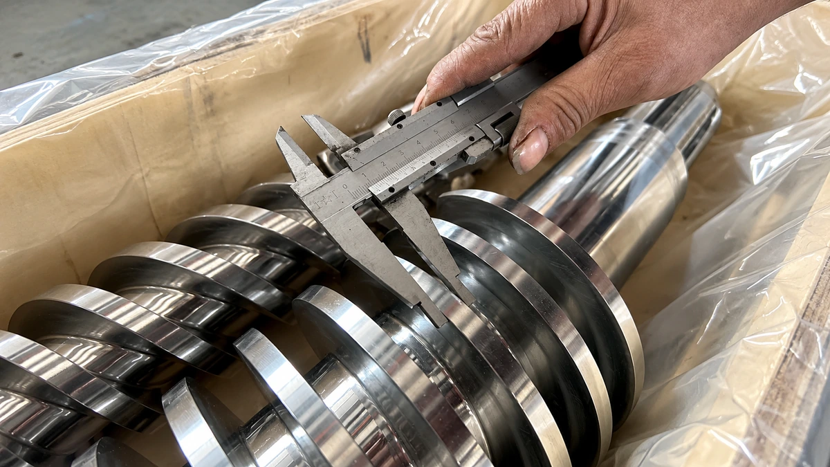
Extrusion Screw Compression Ratio: The Math Most Processors Get Wrong
Nov 2, 2026
Learn how to calculate extrusion screw compression ratio correctly, compare geometric vs. effective ratios, and match compression to every common thermoplastic.
Read Article
Extruder Poor Mixing Problem: Stop Blaming the Screw First
Nov 2, 2026
Fix extruder poor mixing problems fast. Map symptoms like gels, color streaks, and unmelted particles to root causes with our dispersive vs distributive diagnostic guide.
Read Article
Twin Screw Extruder for Recycling: Scrap In, Sellable Resin Out
Oct 30, 2026
Learn how a twin screw extruder for recycling transforms contaminated plastic scrap into sellable pellets. Covers screw design, polymer guides, and line setup.
Read ArticleLooking for something else?
Search by material, symptom or product and jump straight to the relevant page.
These are navigation suggestions based on keyword matching — not a quotation, not a delivery commitment, and not a substitute for engineering review. Final specification is confirmed by our engineers against your drawings and processed material.
Need help with screw barrel selection?
Share your machine model, processed material and application. Our team can help with pricing and technical support.