

How to Spot an Extruder Poor Mixing Problem Before It Worsens
You probably did not search for "dispersive vs. distributive mixing theory" or "screw geometry optimization." You searched because something looks wrong with your parts. Maybe you are pulling color streaks off the line, picking gels out of sheet, or watching mechanical test results scatter across the same production run. That is exactly where effective troubleshooting should start — not with the screw, not with barrel temperatures, but with the defect staring back at you from the product.
An extruder poor mixing problem rarely announces itself with a single, dramatic failure. Instead, it creeps in through subtle visual and measurable clues that operators often dismiss as normal variation. Each clue, however, points toward a distinct root cause. Recognizing the specific symptom is the fastest way to narrow your diagnosis and avoid weeks of trial-and-error adjustments that never reach the real issue.
Visual Defects That Signal Poor Mixing
When you inspect extrudate or finished parts, look for these telltale indicators. Every one of them tells a different story about what is happening — or not happening — inside the barrel:
- Color streaks or swirls: Masterbatch or pigment concentrate is not being spatially redistributed throughout the melt — a distributive mixing failure.
- Gels and fish eyes: Undissolved high-molecular-weight polymer fractions or cross-linked degradation products are surviving the melt process intact, signaling insufficient dispersive stress.
- Unmelted particles or specks: Solid polymer fragments — especially from regrind with inconsistent particle size — are passing through the metering zone without fully melting, indicating inadequate shear or residence time.
- Uneven surface gloss: Localized viscosity differences within the melt create regions that cool and solidify at different rates, producing matte and glossy patches on the same part.
- Variable part weight or wall thickness: Melt homogeneity is poor enough to cause density and flow-rate fluctuations within a single run.
- Inconsistent melt flow index (MFI) readings: Sample-to-sample MFI variation from the same production batch reveals that the polymer is not reaching a uniform thermal and mechanical history inside the mixer extruder.
- Scattered mechanical properties: Tensile strength, impact resistance, or elongation results that vary widely across parts from the same lot confirm that the melt composition is not uniform.
This guide covers both single-screw and twin-screw extruders — because the symptoms may look identical on the product, yet the underlying causes and corrective actions can be fundamentally different depending on your machine type.
Why a Symptom-First Approach Matters for Troubleshooting
Imagine pulling a sample off the die and spotting fish eyes in an otherwise clear sheet. Your instinct might be to raise barrel temperatures or bump screw speed. But fish eyes from cross-linked degradation demand the opposite response from fish eyes caused by unmelted polymer particles. Treating both the same way guarantees you will make one of them worse.
Operators search with a symptom in mind, not a cause. Nobody types "insufficient elongational flow in the kneading zone" into a search bar — they type what they see. Working backward from defects to root causes is therefore the most practical diagnostic method on a production floor. Unlike a kitchen scenario where even a basic stand mixer with meat grinder and sausage extruder attachments or a kitchenaid stand-mixer pasta-extruder attachment kpexta ksmpexta can deliver visibly acceptable results through simple mechanical action, industrial extrusion demands precise control over shear, stress, and residence time to achieve true homogeneity.
Simple conveying does not equal mixing. Polymer can exit an extruder fully melted and thermally processed yet remain poorly mixed — carrying hidden concentration gradients, undispersed additive clusters, and viscosity variations that only reveal themselves as defects in the finished product.
The sections ahead map each symptom back to its specific root cause, distinguish between dispersive and distributive mixing failures, and provide corrective actions tailored to your extruder type. Every defect you spotted in the list above has a traceable origin — and a targeted fix that does not require guessing.
Dispersive vs Distributive Mixing in Extruders Explained
Every extruder poor mixing problem falls into one of two categories — or a combination of both. Yet most troubleshooting advice treats "mixing" as a single, monolithic concept. Add more kneading blocks. Raise the screw speed. Increase back pressure. These blanket recommendations ignore a fundamental reality: the mechanism that breaks apart a pigment agglomerate is completely different from the mechanism that distributes that pigment evenly throughout the melt. Confusing the two is the single most common reason mixing problems persist even after operators make process changes.
Think of it this way. A screw conveying polymer down a barrel is doing exactly that — conveying. Material follows a helical path, gets compressed, melts through a combination of shear heating and barrel conduction, and eventually exits the die. But along that journey, the melt can remain remarkably stratified. Layers of material that entered the feed throat together may travel side by side through the entire barrel, never truly interchanging. The polymer is processed, yes. Mixed? Not necessarily.
Two distinct flow phenomena govern real mixing inside an extruder: shear flow and elongational flow. Shear flow arises when adjacent layers of melt slide past each other at different velocities — picture a deck of cards being fanned. Elongational flow occurs when material is stretched, pulled, or squeezed through a converging passage. As Technovel's extrusion engineering team explains, elongational flow plays a critical role in dispersive mixing and must be considered alongside shear flow, not overlooked in favor of it. Both flow types generate stress on particles and domains within the melt, but they do so in fundamentally different ways — and they solve different problems.
Dispersive Mixing and Breaking Down Agglomerates
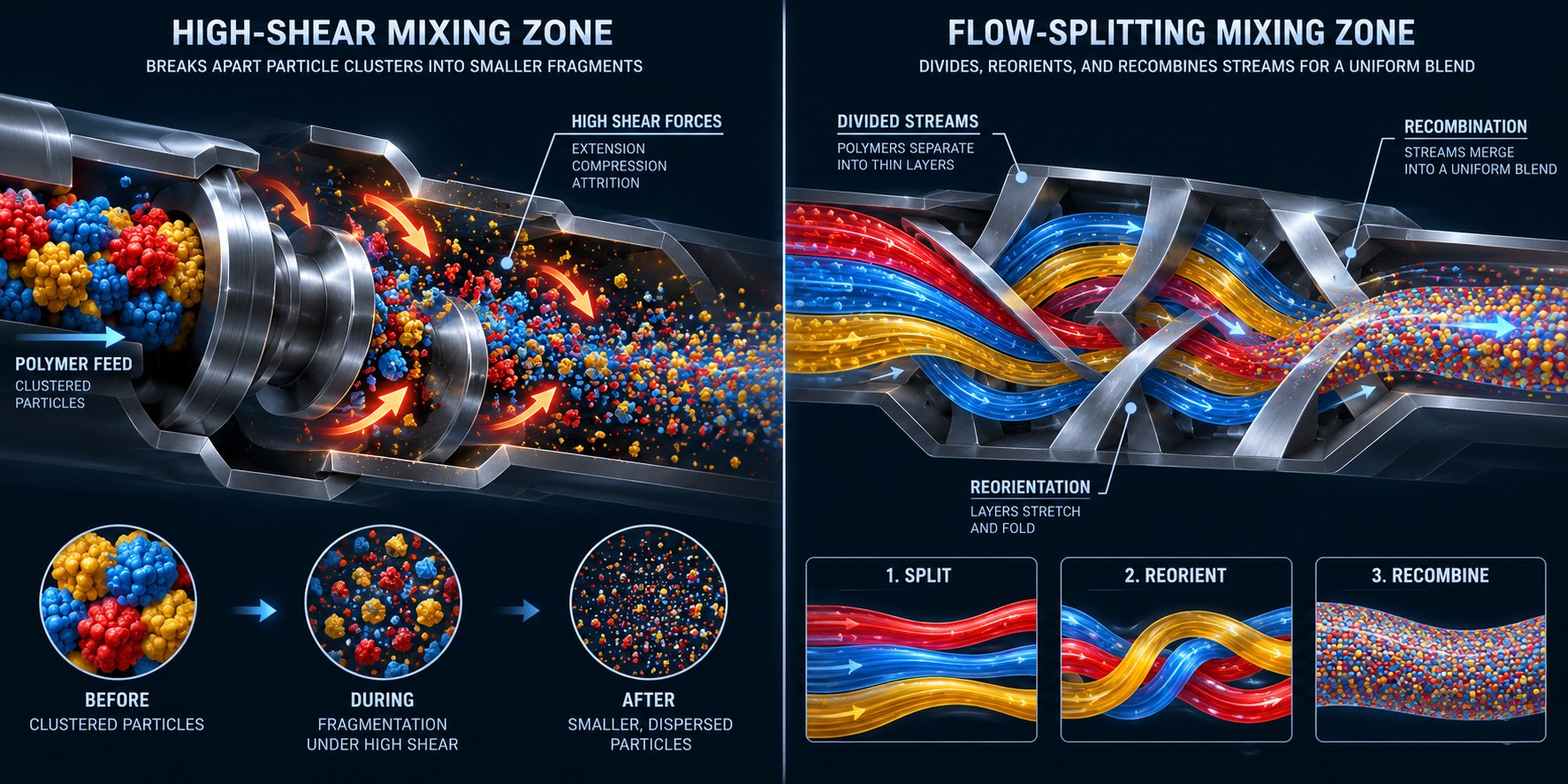
Dispersive mixing is all about size reduction. It is the process that overcomes cohesive forces holding agglomerates, gels, large filler clusters, and oversized polymer domains together, breaking them into smaller units. Imagine a clump of carbon black particles bonded together by van der Waals forces. To separate those particles, the surrounding melt must exert stress — shear stress, elongational stress, or both — that exceeds the cohesive strength binding them.
This demands high-intensity mechanical energy concentrated in specific zones. In a double arm mixer extruder or a sigma blade mixer extruder designed for batch processing, dispersive mixing happens through aggressive mechanical kneading in a confined space. In continuous extrusion, dispersive action concentrates at narrow gaps — the tip clearance between screw flights and the barrel wall, or the intermeshing region of twin-screw elements — where material is forced through tight passages and subjected to intense stress.
When dispersive mixing is insufficient, you will see the telltale defects listed in the previous section: gels and fish eyes from undissolved high-molecular-weight polymer fractions, visible filler clusters, undispersed pigment specks, and inconsistent mechanical properties caused by large domains of unmixed minor phases. The particles or domains are present — they simply have not been broken down to a functional size. Research from Paderborn University using 3D CFD simulations with particle tracking confirmed that screw element geometry and rotation speed have a significant influence on the shear stresses particles experience, directly affecting how effectively agglomerates break apart during processing.
Distributive Mixing and Achieving Spatial Uniformity
Distributive mixing solves an entirely different problem. Even after agglomerates are broken down to an acceptable particle size, those particles can remain concentrated in one region of the melt. Distributive mixing spatially rearranges already-sized minor components — pigments, additives, fillers, secondary polymer phases — uniformly throughout the major phase.
How does this happen? Through repeated splitting, reorienting, and recombining of flow streams. Every time the melt stream divides around an obstacle, passes through a channel split, or gets folded back on itself, minor components get redistributed across new spatial positions. The more divisions and recombinations, the more uniform the final distribution becomes. Distributive mixing relies heavily on strain — the cumulative deformation the material experiences — rather than peak stress.
Poor distributive mixing produces a distinct set of symptoms. Color streaks persist even when pigment particles are adequately fine. Additive concentrations vary across the cross-section of a profile. Mechanical properties shift from one side of a sheet to the other. The particle size is correct, but the spatial arrangement is not. You might see this clearly when running double arm mixer extruders in compounding applications: the compound exits with well-ground filler particles that are clustered in pockets rather than spread evenly through the matrix.
The Paderborn University study found that toothed mixing elements (ZME) consistently outperformed standard kneading blocks for distributive mixing, achieving lower mixing index values — meaning more uniform particle distribution — across all tested rotation speeds. Critically, conveying elements alone provided very poor distributive mixing regardless of how fast they turned, reinforcing the principle that conveying does not equal distributing.
Why Both Types Must Be Addressed Separately
Here is where most troubleshooting efforts go sideways. An operator sees color streaks and installs aggressive kneading blocks. The kneading blocks generate enormous shear stress — excellent for dispersive mixing — but they do not necessarily create the repeated stream-splitting geometry needed for distributive mixing. The color streaks persist, and the operator concludes the extruder "just can't mix this formulation." In reality, the wrong type of mixing element was applied to the wrong type of mixing problem.
The reverse mistake is equally common. A plant running a mixer extruder adds distributive mixing elements to solve a gel problem. The gels require high stress to rupture, but distributive elements are designed to rearrange flow — not to crush agglomerates. The gels survive, and the operator is left wondering why an expensive screw modification produced no improvement.
Residence time distribution adds another layer of complexity. Material does not spend a uniform amount of time in each zone of the extruder. Some fraction races through the channel center while other material lingers near the barrel wall. A wide residence time distribution means some material receives far more mixing than average, while some receives far less. Both dispersive and distributive mixing quality depend not just on the intensity of the mixing action, but on whether every particle of material actually experiences that action for an adequate duration.
The table below lays out the critical differences between dispersive and distributive mixing. Use it as a quick reference whenever you are diagnosing an extruder poor mixing problem — identifying which type of mixing is deficient will immediately narrow your corrective action options by half.
| Dimension | Dispersive Mixing | Distributive Mixing |
|---|---|---|
| Purpose | Break agglomerates, gels, and large domains into smaller units | Spatially rearrange already-sized components uniformly throughout the melt |
| Primary mechanism | High shear stress and elongational stress exceeding cohesive forces | Repeated splitting, reorienting, and recombining of flow streams |
| Stress requirement | High peak stress — stress must exceed agglomerate cohesive strength | Moderate stress — cumulative strain and number of reorientations matter more |
| Key flow type | Elongational flow is especially effective; high-shear flow also contributes | Complex three-dimensional flow with frequent stream division |
| Typical defects when lacking | Gels, fish eyes, undispersed filler clusters, pigment specks, inconsistent mechanical properties | Color streaks, concentration gradients, uneven additive distribution, variable surface gloss |
| Example mixing elements | High-shear kneading blocks (90 degree stagger), Maddock mixers, narrow tip clearance elements, toothed mixing elements (ZME) | Distributive kneading blocks (30 degree stagger), pin mixers, cavity transfer mixers, toothed mixing elements (ZME), static mixers |
| Screw speed effect | Higher speed increases shear stress but may reduce residence time and limit exposure duration | Higher speed improves stream-splitting frequency but also shortens residence time |
Notice that toothed mixing elements appear in both columns. This is not a mistake — certain element geometries deliver meaningful dispersive and distributive performance simultaneously, which is why screw configuration is as much an art as a science. The Paderborn research demonstrated this directly: ZME elements generated high shear stresses for dispersive mixing while also achieving the best particle distribution scores among all tested geometries.
With this framework in hand, every symptom from the previous section now maps to a specific mixing deficiency. Gels point to dispersive failure. Color streaks point to distributive failure. Multiple symptoms appearing together suggest both types are inadequate — which is common when a screw was designed purely for conveying with no dedicated mixing zones at all. The next challenge is translating these categories into a structured diagnostic tool that connects each symptom to its most likely root causes and corrective actions.
Mapping Mixing Defects to Root Causes and Fixes
Categories are useful. Knowing that gels signal a dispersive failure and color streaks point to a distributive one narrows the diagnostic field considerably. But on the production floor, you need more than categories — you need a direct line from the defect you are holding in your hand to the specific corrective action that eliminates it. That is exactly what the reference table below provides: a structured lookup tool connecting every major mixing-related symptom to its most probable root causes, the extruder types affected, and the targeted fix. Whether you are running a laboratory mixing extruder qualifying a new formulation or troubleshooting mixer extruders on a full-scale production line, the diagnostic logic is the same.
Symptom-to-Cause-to-Solution Reference Table
This table covers the eight most common observable symptoms tied to an extruder poor mixing problem. Each row is designed to be self-contained — find your dominant defect, read across, and move directly to the recommended corrective action.
| Observable Symptom | Most Likely Root Causes | Extruder Type Affected | Recommended Corrective Action |
|---|---|---|---|
| Color streaks or swirls | Poor distributive mixing; insufficient stream-splitting elements; masterbatch letdown ratio too high; inadequate residence time for spatial redistribution | Both (more common in single-screw) | Add distributive mixing elements (pin mixers, cavity transfer mixers, or 30-degree kneading blocks); verify masterbatch letdown ratio; consider adding a static mixer downstream of the screw tip |
| Gels and fish eyes | Insufficient dispersive stress to break down high-molecular-weight fractions or crosslinked particles; degradation-generated crosslinked gels from stagnant zones; contamination from previous material | Both | Increase dispersive mixing intensity (90-degree kneading blocks, Maddock mixer, tighter flight clearance); purge stagnant zones thoroughly; inspect screw and barrel for dead spots; check for thermal degradation from excessive residence time |
| Unmelted particles | Inadequate compression ratio for the polymer; insufficient barrel length (L/D too short); barrel temperature profile too low in transition zone; worn screw flights reducing shear input; regrind with oversized particles | Both (especially single-screw) | Verify compression ratio matches the polymer; increase transition zone temperatures; check flight clearance for wear; standardize regrind particle size; consider a barrier screw design for single-screw systems |
| Specks or black specks | Carbonized polymer from dead zones in the barrel, adapter, or die; degraded material on screw flights or in flight root radii; contamination from previous material run; inadequate purging between changeovers | Both | Perform thorough purge with appropriate purge compound; disassemble and clean adapter and die flow channels; inspect screw for carbon buildup in root radii; review shutdown and startup procedures to prevent polymer stagnation |
| Uneven surface gloss | Viscosity variations within the melt from incomplete thermal and compositional homogenization; localized temperature gradients creating regions that cool at different rates; poor distributive mixing of additives that affect surface properties | Both | Improve distributive mixing to homogenize melt composition; verify barrel temperature profile eliminates hot and cold spots; add a static mixer before the die to equalize melt temperature; check that slip agents or processing aids are evenly distributed |
| Variable mechanical properties | Non-uniform filler or reinforcement distribution (dispersive and distributive failure); inconsistent polymer blend morphology; wide residence time distribution allowing some material to be over-processed while other material is under-processed | Both (critical in twin-screw compounding) | Review screw configuration for adequate dispersive and distributive zones; narrow residence time distribution by adjusting feed rate and screw speed balance; verify filler feeding consistency; for new mixer extruders or screw upgrades, specify elements that address both mixing types |
| Inconsistent melt flow index (MFI) | Non-uniform thermal history across the melt cross-section; degradation variation from wide residence time distribution; uneven additive (stabilizer) distribution; feed blending inconsistency upstream of the extruder | Both | Improve melt temperature uniformity with static mixer or optimized barrel profile; narrow residence time distribution; verify upstream blending equipment is delivering consistent composition; check that stabilizer package is properly dispersed |
| Surface roughness (non-melt-fracture) | Unmelted or partially melted particles reaching the die; incompatible polymer phases that are not adequately dispersed; moisture-induced splay in hygroscopic resins mistaken for mixing defects | Both (single-screw more prone to unmelt-related roughness) | Distinguish from melt fracture by checking whether roughness worsens at higher output (melt fracture) or persists regardless of rate (mixing failure); increase dispersive mixing; verify material is properly dried; inspect for worn screw flights |
How to Use This Diagnostic Map on the Production Floor
A table this detailed is only useful if you follow a disciplined workflow. Resist the temptation to scan every row and start changing five things at once. Instead, follow this sequence:
- Step 1 — Identify the dominant defect. Pull samples and isolate the single most prominent symptom. Is it primarily color streaks? Gels? Unmelted particles? Multiple defects often appear together, but one will be the most severe or the most frequent.
- Step 2 — Cross-reference the table. Find the matching row and read the root causes column. Ask yourself which cause best fits your situation — your material, your screw design, your recent process history.
- Step 3 — Check the extruder type column. Some causes apply universally, while others are far more likely in a single-screw or twin-screw system. This distinction eliminates irrelevant possibilities immediately.
- Step 4 — Move to the corrective action. The later sections of this article provide detailed guidance on each corrective approach — single-screw-specific fixes, twin-screw configuration adjustments, temperature and back pressure optimization, and material-related solutions. Use the table to point you toward the right section.
Here is one of the most powerful aspects of this diagnostic approach: when multiple symptoms appear together, they narrow down root causes dramatically rather than expanding the possibilities. Color streaks combined with variable mechanical properties, for example, point strongly toward a distributive mixing deficiency with an upstream feeding component. Gels combined with black specks suggest thermal degradation in a stagnant zone — a completely different root cause than gels appearing alone. Use the overlap between rows to zero in faster.
Always identify the PRIMARY symptom first. Trying to fix every defect simultaneously scatters your effort across multiple corrective actions that may conflict with each other. Solve the dominant problem, then reassess — you may find the secondary symptoms have already improved.
This table serves as your entry point, not your entire toolkit. Each corrective action listed here connects to deeper mechanical, thermal, and material-related factors that determine whether the fix sticks. The most immediate of those factors — and the one that defines the mixing ceiling for millions of extruders worldwide — is the fundamental geometry of the screw itself and how it interacts with the polymer inside the barrel.
Single-Screw Extruder Mixing Failures and Their Origins
Single-screw extruders are the workhorses of the plastics industry, running everything from blown film lines to profile extrusion to 3d printer mixing extruder hotends. Yet their fundamental design purpose is conveying and pressurizing — not mixing. Mixing is, at best, a secondary outcome. This distinction matters because it means every single-screw extruder starts with a built-in handicap when the application demands high levels of melt homogeneity. Understanding why that handicap exists is the first step toward compensating for it effectively.
Why Single-Screw Extruders Struggle with Mixing
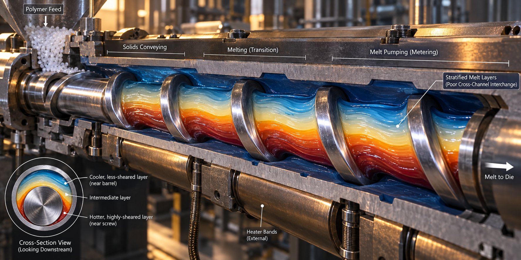
Picture the polymer inside a single-screw channel. After it melts, it largely rotates with the screw in a helical path, dragged along by friction against the barrel wall. The velocity profile across the channel depth creates some shear — maximum at the barrel surface, minimum at the screw root — but the cross-channel flow that would actively interchange material between different radial positions is limited.
As extrusion expert Jim Frankland explains, the channel contents tend to stay in relatively the same radial position due to continuing shear thinning, with viscosity decreasing from the barrel surface toward the screw root. The result is a form of stratification: a thin melt film on the barrel wall gets scraped and recirculated by the advancing flight, but the solid bed and melt pool below it have limited interchange. Material that enters the feed throat in a particular cross-channel position can travel the full barrel length without ever truly exchanging position with material in a different layer.
Compare this to a twin-screw extruder, which can transfer the entire channel of polymer from one screw to the other multiple times, achieving full-channel mixing with minimal pressure penalty. The single-screw simply lacks an equivalent mechanism. It has one channel, one helical path, and limited opportunities to force radial repositioning of the melt.
Screw Design Factors That Degrade Single-Screw Mixing
The inherent limitation described above gets worse when screw design choices are wrong for the application. You will often find that an extruder poor mixing problem on a single-screw line traces back to one or more of these specific design deficiencies:
- Inadequate compression ratio: A compression ratio too low for the polymer fails to generate sufficient shear in the transition zone. Material melts slowly and incompletely, arriving in the metering section with residual solid fragments that never receive adequate mixing energy.
- Wrong L/D ratio for the application: A screw that is too short simply does not provide enough residence time or cumulative strain to achieve homogeneity — particularly with color mixing extruder applications or formulations containing high filler loadings that demand extended mixing exposure.
- Absence of dedicated mixing sections: Many general-purpose single screws are designed with feed, transition, and metering zones only — no mixing geometry whatsoever. Every ounce of "mixing" relies on whatever incidental shear and cross-channel flow the basic screw geometry provides, which Frankland confirms is fundamentally insufficient for anything beyond simple homogenization.
- Worn flight clearances: As the clearance between flight tip and barrel wall increases from wear, polymer leaks over the flight without being subjected to the high shear that this narrow gap normally provides. This progressively degrades both dispersive action and the scraping mechanism that represents the single-screw's primary mixing event.
- Incorrect channel depth profile: Single screws must maintain specific channel depths to hit their target output and melt temperature. Unlike twin screws, which run starve-fed and can incorporate multiple high-shear zones freely, single-screw channel depths are constrained by throughput requirements — leaving little room for aggressive mixing geometry without sacrificing output.
Plants that once ran simpler formulations often discover these design gaps when they switch to more demanding materials — higher filler loadings, tighter color specifications, or recycled feedstock blends where consistency is already compromised before the material enters the hopper. What used to be "good enough" mixing suddenly is not, and the same screw that performed adequately for years becomes the bottleneck.
The Role of Static Mixers and Mixing Heads
The good news is that single-screw systems do not have to live with their inherent mixing limitations. Adding specialized mixing devices downstream of the screw — or incorporating them into the screw itself — can dramatically improve homogeneity without replacing the entire machine.
The key is matching the mixing device to the type of mixing deficiency you diagnosed earlier using the dispersive vs. distributive framework:
For dispersive mixing problems — gels, fish eyes, undispersed filler clusters — the Maddock mixer remains one of the most effective solutions for single-screw extruders. Frankland, who was involved in early Maddock mixer manufacturing and testing, describes how its design was inspired by twin-screw mixing principles: it forces complete turnover of the entire melt stream and applies short-term high shear as polymer passes over a barrier from inlet to outlet flutes. This combination of full-channel turnover and concentrated shear addresses both the stratification problem and the need for stress exceeding agglomerate cohesive forces. The limitation, however, is that its inherent pressure drop makes it difficult to use multiple Maddock sections in series without significant output loss and melt temperature rise.
For distributive mixing problems — color streaks, concentration gradients, uneven additive distribution — pineapple mixers, pin mixers, and cavity transfer mixers are better choices. These designs divide and recombine the melt stream repeatedly at relatively low shear stress, achieving the spatial redistribution that a standard metering section cannot provide. Cavity transfer mixers, with their alternating hemispherical cavities on the screw and barrel surfaces, are particularly effective for color mixing extruder applications where pigment particle size is adequate but spatial uniformity is not.
For both types simultaneously — or when you are not yet certain which deficiency dominates — an extruder melt tube static mixer installed between the screw tip and the die provides a valuable "catch-all" improvement. Research from the Institute for Plastics Processing (IKV) at RWTH Aachen University demonstrated that X-type static mixers significantly improve both thermal and material homogeneity by splitting and redistributing the melt flow through numerous flow divisions and recombinations. Their experimental validation showed that optimized static mixers reduced core melt temperature by up to 6 degrees Celsius while simultaneously improving distributive mixing — all without any modification to the screw itself. Static mixers add no moving parts, require no separate drive, and can be retrofitted into existing extrusion lines, making them one of the lowest-risk interventions available for plants dealing with used double arm mixer extruders or aging single-screw equipment where a full screw rebuild is not yet justified.
The trade-off with every downstream mixing device is the same: additional pressure drop. More mixing elements mean more flow resistance, which reduces throughput and can elevate melt temperature — potentially creating new problems even as the original mixing deficiency improves. Selecting the right type and quantity of mixing elements requires balancing mixing quality against output and thermal limits, which is why the dispersive vs. distributive diagnosis from Section 2 is so critical. It prevents you from installing hardware that addresses the wrong problem.
Single-screw extruders face real, physics-based constraints on their mixing capability. But the picture looks entirely different on twin-screw machines, where modular screw design and intermeshing geometry provide mixing options that a single screw can only approximate. The challenge with twin-screw extruders is not the absence of mixing potential — it is the surprising number of ways that potential gets squandered through configuration mistakes and process parameter mismatches.
Twin-Screw Extruder Mixing Problems and Configuration Errors
Twin-screw extruders enjoy a well-earned reputation as superior mixing machines. Their intermeshing geometry transfers material from one screw to the other, creating the kind of full-channel turnover that a single screw can only dream about. Their modular screw design lets engineers swap conveying elements, kneading blocks, and specialized mixing sections to build a configuration tailored to virtually any formulation. So why do twin-screw lines still produce color streaks, gels, and inconsistent mechanical properties? Because superior mixing capability and actual mixing performance are not the same thing. A co-rotating twin-screw extruder configured or operated incorrectly can deliver results just as disappointing as an undersized single-screw machine — sometimes worse, because the assumption that "twin-screw means well-mixed" delays diagnosis and lets defects persist for weeks.
The flexibility that makes twin-screw systems so powerful is also what makes them vulnerable to configuration mistakes. A single-screw operator has limited mixing options to get wrong. A twin-screw operator, on the other hand, can choose from dozens of element combinations, stagger angles, sequencing strategies, and zone lengths — each of which dramatically changes how the polymer is processed. Get those choices right, and you have a continuous mixer extruder capable of handling the most demanding compounding applications. Get them wrong, and you have an expensive conveyor that melts polymer without truly mixing it.
Screw Configuration Mistakes in Twin-Screw Extruders
The most consequential configuration decision in any twin-screw extruder is how kneading blocks are arranged — specifically, their stagger angle. This single variable shifts extruder mixing behavior from gentle distributive action to aggressive dispersive processing, and getting it wrong is the most frequent source of twin-screw mixing failures.
Imagine three kneading discs stacked on a splined shaft. The angular offset between each consecutive disc — 30 degrees, 60 degrees, or 90 degrees — determines how material flows through the block. At a 30-degree forward stagger, the discs act almost like a conveying element with enhanced flow splitting. Material moves forward smoothly, getting divided and recombined along the way. At a 90-degree stagger (often called a neutral kneading block), net forward conveying drops to nearly zero. Material oscillates back and forth across the disc faces, subjected to intense shear and pressure fluctuations that can fracture even stubborn agglomerates. A CPM engineering guide on twin-screw screw design emphasizes that narrower discs combined with higher stagger angles intensify local pressure fluctuations and shear gradients, boosting dispersive action — but also raising melt temperature and torque significantly.
The table below lays out how stagger angle affects every critical mixing parameter. Use it as a quick reference when evaluating whether your current kneading block arrangement matches your mixing deficiency.
| Stagger Angle | Mixing Type Emphasis | Shear Intensity | Residence Time Impact | Best Application |
|---|---|---|---|---|
| 30 degrees (forward) | Primarily distributive — repeated stream splitting with forward conveyance | Low to moderate | Minimal increase; material moves through quickly | Color masterbatch distribution, temperature-sensitive polymers, fiber-reinforced compounds where fiber breakage must be minimized |
| 60 degrees (forward) | Balanced dispersive and distributive — moderate shear with meaningful flow rearrangement | Moderate to high | Moderate increase; some back-mixing occurs | General-purpose compounding, filler wetting and initial dispersion, polymer blending with moderate viscosity ratios |
| 90 degrees (neutral) | Primarily dispersive — strong shear and pressure gradients with near-zero net conveying | High | Significant increase; material recirculates across disc faces | Deagglomeration of hard pigment clusters (carbon black, TiO2), breaking down crosslinked gels, incompatible polymer blend morphology refinement |
| Reverse kneading blocks | Aggressive dispersive — backward pumping creates intense pressure build-up upstream | Very high | Large increase; strong back-mixing and extended exposure | Melt seals for devolatilization zones, extreme deagglomeration needs, high-fill-level creation upstream of vent ports |
Here is where the mistakes happen. The three most common kneading block configuration errors are:
- Using 90-degree blocks to solve a distributive problem. An operator sees color streaks — a distributive failure — and installs aggressive neutral kneading blocks. The high shear generates heat and torque but does not create the repeated stream-splitting geometry that distributive mixing requires. The color streaks persist, and the polymer may now show degradation signs as well.
- Incorrect kneading block sequencing. Placing intense dispersive blocks too early in the screw — before the polymer is fully molten — forces solid fragments through high-shear zones. The result is unstable torque, unmelted particles surviving into downstream zones, and surging output. The CPM guide confirms that placing intense dispersive mixing elements before the material is fully molten leads to unmelted particles and unstable operation.
- Insufficient total mixing zone length. A single short kneading block section cannot compensate for an otherwise all-conveying screw. Extruder mixing quality depends on cumulative strain — the total number of times the melt stream gets divided, sheared, and recombined. A three-disc kneading block followed by meters of conveying elements simply does not provide enough reorientations to achieve uniform distribution, even if that single block is perfectly configured.
Beyond kneading blocks, twin-screw extruders benefit from specialized elements — toothed mixing elements (ZME), blister rings, and interrupted conveying sections — that provide additional distributive or dispersive action without the aggressive thermal penalty of high-stagger kneading blocks. Selecting the right combination requires knowing whether your defect is dispersive, distributive, or both, which is exactly why the framework from Section 2 matters so much on twin-screw lines.
Process Parameters That Undermine Twin-Screw Mixing
Even a perfectly configured screw can deliver poor results when process parameters fight against the mixing design. Twin-screw extruders present a unique challenge because several key parameters interact in ways that are not always intuitive.
Screw speed is the most misunderstood variable. Raising RPM increases shear rate — which should improve dispersive mixing. But it simultaneously reduces residence time by pushing material through the barrel faster. If the mixing problem is dispersive, the higher shear may help. If the problem is distributive, the shorter residence time can actually make things worse because the melt experiences fewer splitting-and-recombining events before exiting the die. Operators who reflexively crank up speed to "mix better" sometimes degrade the very quality they are trying to improve.
Feed rate and starve-feeding add another dimension. Co-rotating twin-screw extruders typically run in starve-fed mode, meaning the feed rate — not the screw speed — determines throughput. Changing the feed rate alters the fill level in each barrel section. Lower feed rates reduce fill, which decreases the amount of material in the kneading zones and can reduce mixing effectiveness because the elements are not working on a continuous, fully engaged melt stream. Excessively high feed rates push the extruder toward flood-fed conditions that change residence time distribution and can overwhelm the mixing capacity of the configured kneading sections.
Barrel temperature profiles that do not match the polymer's rheological needs create viscosity mismatches zone by zone. Too much heat in the early barrel sections melts the polymer prematurely, dropping viscosity before the material reaches the primary mixing zone. Lower viscosity means lower shear stress at a given shear rate — which directly reduces dispersive mixing effectiveness. Too little heat, and the polymer arrives at the kneading blocks partially solid, creating the same sequencing problem as placing dispersive elements too early.
Co-rotating vs. counter-rotating geometry also changes mixing behavior fundamentally. Co-rotating intermeshing twins (the most common configuration) generate open, figure-eight flow patterns with high shear at the intermesh and good material transfer between screws. Counter-rotating intermeshing twins create closed C-shaped chambers that trap material and convey it more positively, producing higher pressures but more limited mixing per unit length. Diagnosing an extruder poor mixing problem without considering which geometry you are running can send you down the wrong corrective path entirely.
Scale-Up Mixing Problems Unique to Twin-Screw Systems
You developed a flawless formulation on a laboratory twin-screw extruder. Color is perfect, mechanical properties are consistent, gels are absent. You transfer the screw configuration to a production-scale machine, set proportional process parameters — and the first samples off the line show streaks, inconsistent MFI, and filler clusters that were not there at lab scale. What happened?
Scale-up is one of the most underestimated sources of mixing failures in twin-screw extrusion, and it cannot be solved by simply multiplying lab settings by a diameter ratio. As Technovel Corporation's scale-up analysis explains, real operating conditions rarely follow a single scaling law. Two competing models frame the challenge:
- The cubic law (Q proportional to D cubed) scales throughput based on volumetric capacity. When you move from a 15 mm screw diameter to a 60 mm diameter — a factor-of-four increase — throughput theoretically jumps by a factor of 64. Productivity soars, but the shear history each particle of material experiences changes dramatically because peripheral speed increases with diameter.
- The square law (Q proportional to D squared) scales throughput based on heat transfer surface area. The same diameter jump produces only a 16-fold throughput increase, but the thermal history of the material is better preserved because the ratio of surface area to volume stays more balanced.
In practice, scale-up conditions land somewhere between these two models. The critical issue for mixing is this: as screw diameter grows, the internal flow volume increases with the cube of the diameter while the barrel surface area — the primary heat exchange interface — increases only with the square. This geometric divergence means heat transfer becomes progressively less efficient relative to the volume of material being processed. Temperature gradients widen, viscosity uniformity suffers, and shear stress distributions shift. Technovel's analysis confirms that applying identical temperature settings and rotational conditions from a smaller machine to a larger one will not reproduce the same temperature history.
Three specific mixing-related consequences emerge during scale-up:
- Shear rate distributions shift. The peak shear at the intermesh zone scales differently from the average shear across the full channel cross-section. Elements that produced uniform dispersive action on a 26 mm lab extruder may leave under-sheared regions on a 92 mm production machine.
- Residence time distributions widen. Larger channel volumes create more opportunity for material to take fast and slow paths through the mixing zone. Some polymer races through in seconds while other fractions linger, producing a broader spread of thermal and mechanical histories — and inconsistent mixing quality.
- Melt temperature uniformity degrades. Reduced heat transfer efficiency means the barrel temperature set points have less influence on the actual melt temperature in the center of the channel. Viscous shear heating dominates, and temperature gradients across the melt cross-section grow — creating the viscosity variations that undermine both dispersive and distributive mixing.
The practical takeaway is that a formulation qualified on a lab-scale machine almost always needs screw configuration adjustments — not just proportional scaling — when transferred to production equipment. Kneading block sequencing, zone lengths, disc widths, and stagger angles often require reoptimization because the physics of mixing are inherently scale-dependent. Plants that skip this step and assume a proven lab configuration translates directly to production scale are setting themselves up for persistent mixing defects that resist simple process parameter adjustments.
Configuration and scale-up errors account for a large share of twin-screw mixing failures, but they are not the only culprits. Some of the most stubborn mixing problems trace back to factors that have nothing to do with screw design — thermal gradients hidden inside the melt, back pressure that is too low to enforce adequate shear history, and slow mechanical wear that erodes mixing performance so gradually that nobody notices until quality complaints start arriving.
Temperature, Back Pressure, and Wear Effects on Mixing
Screw design gets most of the attention when an extruder poor mixing problem surfaces. And for good reason — the screw is the primary mixing tool inside the barrel. But even a perfectly configured screw operates inside a thermal and mechanical environment that can quietly sabotage its mixing performance. Temperature gradients within the melt create viscosity differences that no kneading block can fully overcome. Insufficient back pressure lets undermixed material slide through the barrel without accumulating enough shear history. And screw and barrel wear — the slowest, most invisible culprit of all — progressively robs the system of the tight clearances that make dispersive mixing possible in the first place.
These three factors share a common trait: they tend to be invisible on the operator control panel. Barrel zone temperatures may read exactly on setpoint while the actual melt temperature varies by 20 degrees or more across the cross-section. Die pressure may look stable while the screen pack is too coarse to provide meaningful resistance. Flight clearances may still fall within nominal tolerances while mixing quality has already degraded noticeably. You have to know where to look — and what the symptoms mean — to catch these problems before they become embedded in your baseline defect rate.
How Temperature Gradients Undermine Mixing Quality
Imagine two adjacent streams of polymer flowing side by side through the metering section. One stream sits near the barrel wall, absorbing conducted heat from the heater bands. The other stream flows through the channel center, where barrel heating barely penetrates and viscous shear heating dominates. The temperature difference between these two streams can easily reach 10 to 20 degrees Fahrenheit — and that gap creates a viscosity mismatch that directly undermines mixing.
Here is why that matters. Viscosity governs how much shear stress a mixing element can apply to the polymer. Higher-viscosity material resists flow and receives more shear — more energy, more dispersive and distributive action. Lower-viscosity material flows easily, slipping through mixing zones with less resistance and less mechanical work applied. So the hotter stream, which is already less viscous, gets less mixing. The cooler stream, which is more viscous, gets more. The result is a self-reinforcing gradient: regions that need more mixing receive less, and the melt exits the die with a non-uniform thermal and compositional history.
Jim Frankland's analysis of polymer viscosity and melt temperature illustrates how dramatic these viscosity differences can be. In one example, switching from a 0.35 MI HDPE to a 0.06 MI bimodal HDPE — an 83% increase in viscosity — produced a melt temperature rise that the processor could not control even by drastically reducing barrel temperatures. The key insight is that barrel heaters do not directly control melt temperature. Shear heating from the screw does. The barrel provides what Frankland calls "primarily a thermal jacket over that stretching process." When a processor tries to fix a mixing problem by adjusting barrel temperatures alone, they are often adjusting a secondary influence while the primary driver — viscous dissipation — remains unchecked.
Polymer type amplifies or dampens this effect significantly. Amorphous polymers like polycarbonate and ABS soften gradually over a wide temperature range, meaning small temperature differences produce relatively small viscosity shifts. Semi-crystalline polymers like HDPE, nylon, and PBT undergo a sharp viscosity drop at their crystalline melting point. A five-degree difference in melt temperature near this transition can mean the difference between a still-solid region and a fully molten one — creating extreme viscosity contrasts within the same channel cross-section. Processing semi-crystalline resins on equipment with poor thermal uniformity almost guarantees unmelted particles or viscosity-driven mixing defects, regardless of screw configuration.
Frankland also notes that polymers of the same type can have radically different viscosity-temperature sensitivities. The accompanying data from his analysis shows LDPE viscosity curves at different temperatures clustering closely together, indicating that temperature has a minor effect on viscosity. LLDPE and HDPE, by contrast, show significant viscosity shifts with temperature. This means a mix extruder processing LDPE may tolerate moderate temperature gradients without visible defects, while the same gradients on an HDPE or LLDPE line produce streaks, gels, or inconsistent MFI readings. The resin itself defines how temperature-sensitive your mixing quality will be.
Back Pressure and Die Design as Hidden Mixing Factors
Back pressure is one of the most overlooked variables in mixing quality. When material flows through the extruder too easily — encountering minimal resistance from the screen pack, breaker plate, adapter, and die — it passes through mixing zones without spending enough time under shear. The cumulative strain history drops, distributive mixing suffers from fewer stream-splitting events, and dispersive mixing weakens because material spends less time in high-stress regions.
Think of back pressure as a gatekeeper. It forces the melt to slow down, fill mixing sections more completely, and spend additional time in contact with kneading elements and shear-generating geometries. Without adequate back pressure, even well-designed mixing sections operate at a fraction of their potential because the material simply passes through too quickly to accumulate the strain and stress exposure needed for thorough homogenization.
Several factors influence back pressure, and each one offers a lever for adjusting mixing quality:
- Screen pack mesh size: Finer mesh screens increase flow resistance and raise back pressure. Coarser screens let melt pass through with minimal restriction. Processors sometimes switch to coarser screens to increase output, not realizing they are simultaneously reducing the back pressure that was helping drive mixing quality. As the IQS Directory extrusion reference notes, screens can be used specifically "to increase the die-head pressure" and improve melt homogenization — a functional role that goes beyond simple filtration.
- Breaker plate design: The breaker plate's hole pattern, hole diameter, and plate thickness all contribute to pressure drop. A breaker plate with larger, fewer holes offers less resistance than one with many small holes. Swapping breaker plates is a low-cost way to adjust back pressure without modifying the screw.
- Die geometry: Restrictive die land lengths and narrow flow channels naturally create back pressure. Open, low-restriction die designs — common in large-profile extrusion — provide less resistance and may require compensating measures upstream to maintain mixing quality.
- Adapter and flow channel restrictions: The adapter connecting the barrel to the die, and any inline devices such as a static mixer or melt pump, all contribute to the total system pressure drop. Removing an inline static mixer to reduce melt temperature, for example, simultaneously removes both its mixing contribution and its back pressure contribution — a double loss that can cause a sudden decline in mix quality.
- Melt pump effects: Plants using gear pumps between the extruder and die sometimes find that the pump reduces the pressure the screw must generate, effectively lowering the back pressure the melt experiences inside the barrel. This can improve output stability while inadvertently reducing mixing intensity — a trade-off that needs to be accounted for in the screw design.
The practical diagnostic clue is this: if mixing quality degrades after any change that reduces system pressure drop — switching to coarser screens, opening die lip gaps, removing inline devices — back pressure loss is the likely culprit. The fix is straightforward in concept: restore the pressure drop through finer screens, a more restrictive breaker plate, or dedicated mixing elements that compensate for the lost resistance.
Screw and Barrel Wear as Progressive Mixing Degradation
Temperature gradients and back pressure deficiencies tend to produce sudden or step-change mixing problems — they appear when you change a setpoint, swap a screen, or introduce a new resin. Screw and barrel wear is fundamentally different. It is a slow, continuous degradation that worsens mixing quality so gradually that operators adapt to it without realizing anything has changed. The defect rate creeps up by fractions of a percent per month. Scrap becomes slightly more frequent. Color consistency drifts just enough to trigger occasional customer complaints. By the time someone decides to investigate, the wear has been eroding mixing performance for months — sometimes years.
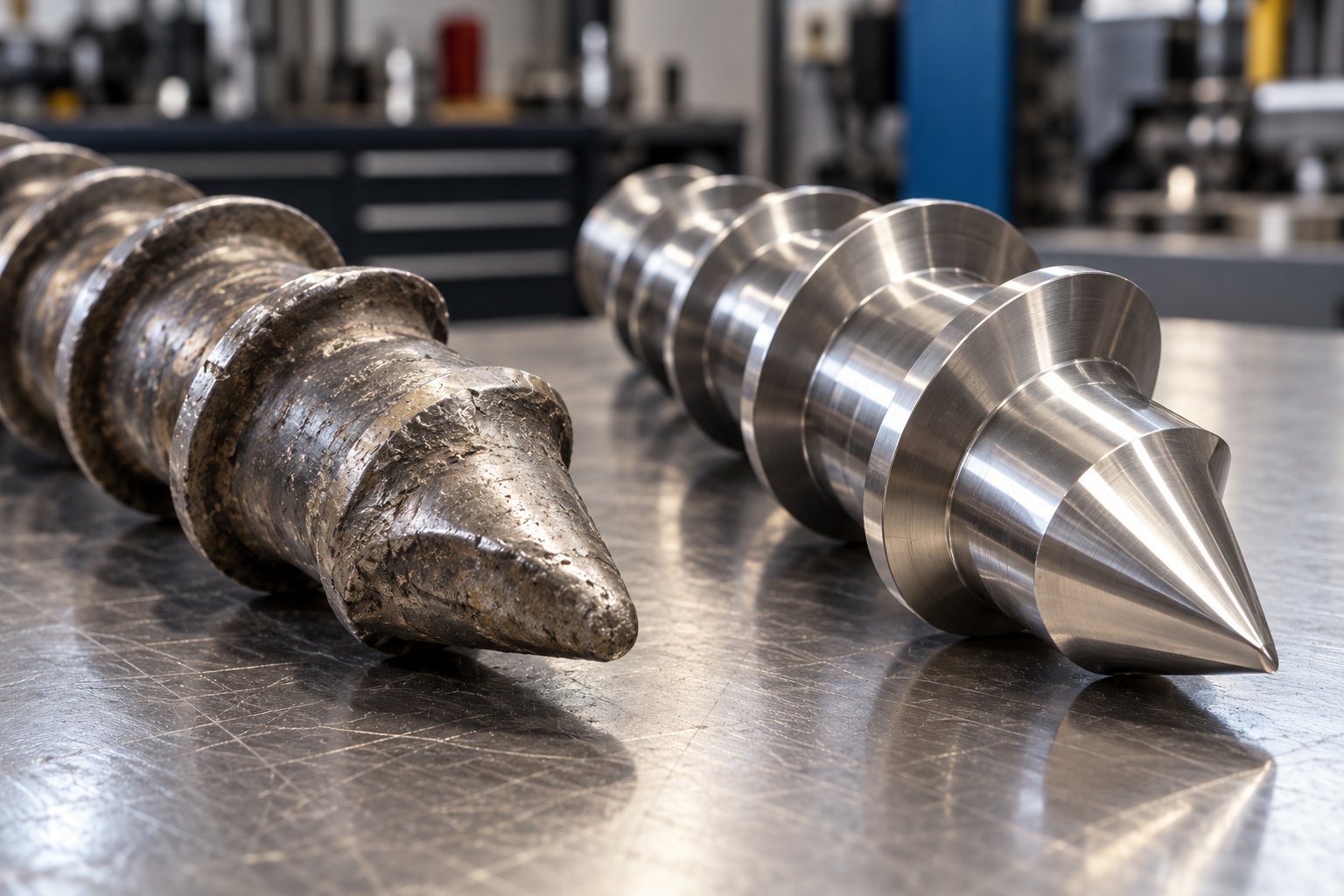
The mechanism is straightforward. As the flight tips wear down and the barrel bore enlarges, the flight clearance — the radial gap between the screw flight and the barrel wall — increases. This gap is where the single-screw's most important mixing action occurs: the thin melt film on the barrel surface gets scraped by the advancing flight and subjected to the highest shear stress anywhere in the channel. As clearance grows, polymer begins to leak over the flights without being scraped or sheared. It bypasses the high-stress zone entirely, flowing from one channel section to the next with minimal mixing input.
MachineCDN's predictive maintenance analysis for extrusion lines quantifies the progression: a new screw typically has flight clearance of 0.002 to 0.004 inches, a marginally worn screw shows 0.006 to 0.010 inches, and a screw requiring replacement exceeds 0.010 inches. At the marginal stage, output at rated RPM drops to 85-95% of baseline, and melt temperature begins running 8 to 15 degrees Fahrenheit above setpoint — both indicators that the screw is working harder to do less. Their data shows that specific energy consumption shifts by more than 10% in screws needing replacement, confirming that wear changes the fundamental energy transfer relationship between the screw and the polymer.
Wear patterns differ dramatically depending on the compound being processed:
- Abrasive compounds — glass-fiber-filled polymers, mineral-filled resins, and recycled materials containing contaminants — wear the flight tips and barrel bore through direct mechanical abrasion. Wear concentrates at the transition zone where solids are being compressed and at mixing elements where filler particles are forced through tight clearances. This wear pattern tends to be relatively uniform across the affected zones and accelerates with filler loading and hardness.
- Corrosive compounds — PVC, flame-retardant formulations, and polymers that release acidic byproducts at processing temperatures — attack the metallurgy of the screw and barrel surfaces chemically. Corrosive wear can be more localized and less predictable than abrasive wear, appearing in zones where temperature is highest or where devolatilization releases reactive gases. Flight tip wear from corrosion often appears uneven, with some flights degrading faster than others depending on their exposure to degradation byproducts.
The critical practical insight is that mixing quality trends can reveal wear before dimensional measurements confirm it. If you are tracking color consistency, gel count, melt temperature deviation from setpoint, or melt flow index variability over time, a gradual worsening trend — absent any process or material changes — strongly suggests progressive wear. MachineCDN's approach to indirect wear measurement during operation tracks output rate at a given RPM, motor amperage trends, and specific energy consumption as leading indicators. By the time you pull the screw and measure flight clearance directly, the data trail should already have told you the story.
This is why operators should never accept a slowly climbing defect rate as "normal" for their line. If mixing quality was better six months ago under the same process conditions with the same material, something physical has changed — and wear is the most likely candidate. Documenting mixing quality metrics over time creates the baseline that makes wear-related degradation visible before it crosses into customer-complaint territory.
Temperature, back pressure, and wear are all factors that exist outside the screw design itself. They represent the environment in which the screw operates, and they can amplify or negate even the best mixing geometry. Yet there is one more category of influence that sits even further upstream — the material itself. Polymer type, filler characteristics, and the condition of the feedstock entering the hopper impose mixing demands that vary enormously from one formulation to the next. And when those material-level factors are misunderstood, they produce some of the most persistent and confusing misdiagnoses in the industry.
Material Factors and Misdiagnoses That Complicate Mixing
Screw configuration, temperature profiles, back pressure, and wear all live inside the extruder. But the material feeding into that extruder carries its own set of mixing demands — demands that shift dramatically depending on polymer chemistry, filler characteristics, and feedstock condition. Two formulations processed on the same mixing extruder with identical screw geometry and process parameters can produce wildly different mixing outcomes simply because the materials themselves respond to shear, heat, and residence time in fundamentally different ways. Ignoring these material-level variables is how plants end up chasing screw modifications and process tweaks for months without ever reaching the real root cause.
Worse, material behavior differences feed directly into the most damaging category of troubleshooting errors: misdiagnoses. When operators do not understand how a specific resin or filler responds to processing conditions, they apply corrective actions that seem logical on the surface but actually make the defect worse. This section unpacks both sides of that problem — what the material demands and where the diagnostic logic most commonly breaks down.
How Polymer Type and Filler Properties Change Mixing Demands
Not all polymers melt the same way, and that difference alone changes everything about how mixing should be approached. The most fundamental distinction is between amorphous and semi-crystalline polymers — two categories that behave so differently during extrusion that a screw optimized for one can fail spectacularly with the other.
Amorphous polymers like ABS, polycarbonate, and PMMA soften gradually as temperature increases. There is no sharp melting point — just a glass transition temperature where the material shifts from rigid to rubbery, followed by a progressive viscosity decline. This gradual softening means amorphous resins are relatively forgiving during mixing. Small temperature variations across the melt cross-section produce moderate viscosity differences, and the mixing extruder can tolerate a wider processing window before defects appear.
Semi-crystalline polymers — HDPE, nylon, polypropylene, PBT, POM — are a different story entirely. These resins have a clearly defined temperature at which the solid polymer melts and becomes a fluid. Below that temperature, the material is essentially solid. Above it, viscosity drops sharply. This narrow melting transition creates a processing cliff: a five-degree temperature difference near the melt point can mean the difference between a fully molten region and a still-solid fragment sitting in the same channel. That is why unmelted particles are far more common in semi-crystalline resin processing — the margin for thermal non-uniformity is razor-thin.
Viscosity level adds another layer. High-viscosity polymers (low MFI grades, high-molecular-weight resins) generate more viscous dissipation during shear, which means the screw's mixing elements can apply higher stress to agglomerates and domains. That sounds like good news for dispersive mixing — and it is, up to a point. But high-viscosity melts also resist flow redistribution, making distributive mixing harder because the stream-splitting and recombining events that redistribute minor components require the melt to actually flow into new spatial positions. Low-viscosity polymers flow easily and redistribute well, but they slip through high-shear zones with less stress applied, weakening dispersive action. Each viscosity regime demands a different shear strategy from the screw design and process parameters.
Filler and additive characteristics impose their own mixing requirements on top of the polymer matrix behavior. The following combinations illustrate how material properties map to specific mixing demands:
- Fine, untreated mineral fillers (calcium carbonate, talc) at high loading: These particles agglomerate readily due to high surface energy. Dispersive mixing must overcome interparticle van der Waals forces to separate clusters. Distributive mixing must then spread the separated particles uniformly. Both types are needed, and the demands intensify with loading level — a 40% CaCO3 compound is exponentially harder to mix than a 10% compound, not merely four times harder.
- Surface-treated fillers (coated CaCO3, silane-treated glass fiber): Surface treatment reduces interparticle cohesion, lowering the dispersive stress threshold required for deagglomeration. However, treated fillers can also reduce the filler-matrix interfacial adhesion that helps anchor particles in place during distributive flow, meaning they may re-agglomerate downstream if residence time in subsequent conveying zones is too long.
- High-aspect-ratio reinforcements (glass fibers, carbon fibers, natural fibers): These materials require gentle handling to preserve fiber length — aggressive dispersive mixing breaks fibers and destroys the mechanical property advantages they provide. A mixing extruder 3d printer filament line compounding carbon-fiber-filled PA, for example, needs kneading blocks configured for adequate wetting and distribution (30-degree forward stagger) without the intense shear of 90-degree neutral blocks that would fragment the fibers.
- Nanoscale additives (nano-clay, carbon nanotubes, graphene): Extremely high surface area creates intense agglomeration tendencies. Dispersive stresses required to separate primary particles or tactoids far exceed those needed for conventional fillers. Standard kneading block configurations often cannot generate sufficient elongational flow for full exfoliation, which is why nanocomposite compounding frequently requires specialized screw elements or multiple mixing passes.
- Liquid additives (plasticizers, process oils, liquid colorants): These do not need dispersive action — they are already molecular-scale. The entire challenge is distributive: spreading the liquid uniformly through the polymer matrix without creating concentration pockets. Injection location along the barrel, injection pressure, and downstream distributive mixing element design matter far more than shear intensity.
- Recycled feedstock blends (mixed-color regrind, post-consumer recyclate): Variable composition, inconsistent particle size, possible contamination, and unknown thermal history combine to impose simultaneous dispersive and distributive mixing demands. The feedstock itself may contain pre-degraded gels, undispersed pigment residues from previous processing cycles, and varying viscosity grades. As Kerke Extruder's compounding guide emphasizes, recycled plastics require additional care because contaminants can damage screw elements or cause uneven mixing — making incoming material screening and preparation at least as important as screw configuration.
The overarching principle is that mixing demands are not fixed — they are material-dependent. A screw that produces flawless results on a neat polypropylene can fail completely when that same PP is loaded with 30% talc. A pasta extruder stand mixer attachment in a kitchen can blend flour and water acceptably because neither component has particle cohesion forces or viscosity-dependent shear requirements. Industrial extrusion compounds are not that forgiving. Every resin grade, filler type, and additive combination brings its own mixing physics to the barrel — and the process must account for those physics specifically.
Common Misdiagnoses That Make Extruder Mixing Worse
Understanding material behavior is half the battle. The other half is avoiding the diagnostic errors that send operators spiraling through weeks of unproductive process changes. These mistakes are not random — they follow predictable patterns rooted in intuitive but incorrect reasoning about how extruders work.
Misdiagnosis #1: Treating mixing problems as temperature problems. This is the most widespread error. An operator sees gels, unmelted particles, or inconsistent surface quality and raises barrel temperatures — the easiest knob to turn. For unmelted particles in a semi-crystalline resin, a temperature increase in the transition zone may indeed help. But for gels caused by insufficient shear, raising temperature lowers viscosity, which reduces the shear stress the mixing elements can apply to the melt. The gels survive, and the hotter melt may now show degradation or discoloration as well. As we discussed in the temperature section, barrel heaters provide primarily a thermal jacket — they do not directly control the mechanical mixing energy applied to the polymer.
Misdiagnosis #2: Increasing screw speed without understanding the trade-off. This is the second most common reflexive response, and it contains a trap that catches even experienced operators.
Increasing screw speed simultaneously raises shear rate and decreases residence time. These two effects work in opposite directions for mixing quality — higher shear improves dispersive action but shorter residence time reduces the cumulative strain and number of reorientations needed for distributive mixing. Operators who raise speed to fix mixing problems without understanding this trade-off often improve one aspect while worsening the other.
The net effect depends on which type of mixing is deficient. If dispersive mixing is the bottleneck — gels, undispersed agglomerates — a moderate speed increase may deliver enough additional shear stress to crack the remaining clusters before residence time drops critically. If distributive mixing is the bottleneck — color streaks, concentration gradients — the speed increase is almost certainly counterproductive because the melt needs more time in the mixing zones, not less. And if both types are deficient, the speed increase helps one while hurting the other, producing a confusing mix of improved and worsened symptoms that makes the next diagnostic step even harder.
Misdiagnosis #3: Adding mixing sections without diagnosing whether the problem is dispersive or distributive. We covered this in the screw configuration sections, but it bears repeating in the misdiagnosis context because it represents the most expensive error. Installing new kneading blocks, mixing heads, or static mixers costs time, money, and production downtime. If those elements address the wrong type of mixing deficiency, the investment produces no improvement — and the operator concludes (incorrectly) that the problem is beyond what screw changes can fix. The dispersive vs. distributive framework from earlier in this article exists precisely to prevent this mistake.
Misdiagnosis #4: Blaming the extruder when the real issue is upstream. This is arguably the most frustrating misdiagnosis because it sends the entire troubleshooting effort in the wrong direction. An operator sees mixing defects, assumes the extruder is not doing its job, and spends weeks modifying process parameters or ordering new screw elements — only to discover that the root cause was never inside the barrel at all. It was in the hopper, the blending station, or the material storage area.
When the Problem Is Upstream, Not in the Extruder
Some mixing defects look identical to screw-related problems but originate entirely before the material enters the feed throat. No amount of screw design optimization can fix a mixing problem whose root cause is inconsistent incoming material. These upstream factors are the most commonly missed culprits:
Inconsistent feed blending. When processors pre-blend virgin resin with masterbatch, additives, or regrind in a hopper blender or gravimetric system, the quality of that blend determines the starting point for the extruder's mixing task. A poorly calibrated gravimetric feeder, a hopper blender with dead zones, or static charge causing additive particles to cling to hopper walls instead of flowing with the resin — all create compositional variation in the feed stream that the extruder must then correct. If the variation exceeds what the screw's mixing zones can homogenize in the available residence time, defects appear in the product. A pasta mixer and extruder in a food processing context faces the same principle: if the dough entering the extruder barrel is not pre-mixed to uniform hydration, the extrusion step cannot fully compensate. Industrial plastics processing at hundreds of kilograms per hour is even less forgiving.
Moisture content variation. Hygroscopic resins like nylon, PET, PC, and TPU absorb moisture that causes splay, bubbles, and surface defects easily misinterpreted as mixing problems. Moisture can also reduce friction and make feeding unstable, creating output fluctuations that further degrade mixing consistency. A dryer malfunction that allows resin moisture to creep above specification may produce intermittent gel-like defects or surface roughness that operators attribute to the extruder — when the real fix is repairing or recalibrating the drying system.
Regrind particle size inconsistency. Regrind is one of the most disruptive feedstock variables for mixing quality. As the Jinxin extrusion troubleshooting guide notes, regrind and flakes may not fall or compact like standard pellets, and variations in particle size can lead to inconsistent feeding and melting. Oversized regrind chunks take longer to melt than standard pellets, arriving at the mixing zones partially solid. Fines from the grinder can bridge in the hopper or aerate in the feed throat, causing feed rate fluctuations. The result is a melt stream with unmelted fragments, thermal non-uniformity, and compositional variation — all of which look like mixing failures but actually originate at the granulator.
Additive metering errors. Volumetric feeders dispensing small quantities of stabilizer, slip agent, or processing aid are particularly vulnerable to metering drift. A feeder that delivers 0.3% stabilizer on average but fluctuates between 0.1% and 0.5% within a single hopper cycle creates concentration gradients that the mixing zones may narrow but cannot fully eliminate. Gravimetric feeders are more precise but still require regular calibration — especially when running fine powders or low-bulk-density additives that can bridge or flood the feed mechanism.
The diagnostic rule is simple: before modifying anything inside the extruder, verify that the material entering the feed throat is consistent in composition, moisture content, particle size, and feed rate. Collect samples directly from the feed stream — not from the storage silo — and test them. If the incoming material is not uniform, fixing the extruder is treating a symptom while the disease persists upstream.
Material variability and diagnostic errors cause frustration partly because they consume time and resources without delivering results. But they also carry a hidden financial cost that compounds over months and years — scrap rates that operators learn to accept, rework hours that never get attributed to mixing, and customer complaints that erode confidence. Quantifying those costs is what transforms a mixing problem from an operational nuisance into a business case that justifies real investment in corrective action.
The Hidden Costs of Poor Extruder Mixing Performance
Every mixing defect that survives the extruder carries a price tag. Some of those prices are obvious — the scrap bin at the end of the line, the rejected lot sitting on a warehouse pallet. Others are almost invisible, buried inside rework labor hours, inflated additive consumption, customer credit memos, and secondary processing failures that nobody traces back to the extruder. The frustrating reality is that most plants never calculate the full cost of an extruder poor mixing problem because the losses are scattered across departments, accounting codes, and time periods that make aggregation difficult. Yet when those scattered costs are finally assembled in one place, the number is almost always large enough to justify corrective action that seemed "too expensive" before anyone did the math.
The True Cost of Ignoring Mixing Problems
Think about what happens after poorly mixed extrudate leaves the die. It does not simply become a defective part and stop there. It triggers a cascade of downstream consequences, each with its own cost layer:
Rejected parts and scrap. This is the most visible cost — parts that fail visual inspection or dimensional checks and go straight to the grinder or waste bin. But even here, the true cost is underestimated. Scrap is not just lost resin. It includes the energy consumed to melt and process that resin, the machine time occupied producing unusable product, and the labor hours spent running, inspecting, and disposing of it. For compounding operations using a sigma blade mixer extruder or twin-screw line, scrap also includes the cost of every additive, filler, and pigment blended into the defective compound — materials that cannot always be reclaimed at their original value.
Failed quality tests. When tensile strength, impact resistance, or elongation results scatter across a production lot due to non-uniform filler distribution or inconsistent polymer blend morphology, the entire lot may be quarantined pending additional testing. The direct cost is the testing itself — lab time, equipment usage, technician hours. The indirect cost is production schedule disruption. A quarantined lot blocks warehouse space, delays shipments, and may force expedited production runs to meet customer delivery dates.
Customer returns and complaints. This is where the financial damage escalates from operational cost to commercial risk. A customer who receives parts with visible color streaks, surface inconsistencies, or variable performance properties does not just return the shipment — they lose confidence in the supplier's process control. Repeated complaints erode pricing power, invite competitive quoting on your business, and in regulated industries (medical, automotive, packaging), can trigger formal corrective action requests that consume engineering resources for weeks. The reference material from Plastics Machinery Manufacturing highlights a telling example: one extruder was compensating for mixing-related quality drift by increasing additive dosages rather than fixing the root cause. Given that formulation costs represent roughly 80 percent of total operating expenditure, even a fractional increase in additive consumption to mask a mixing deficiency compounds into significant cost over a production year.
Inconsistent secondary processing. Poorly mixed extrudate does not just look bad — it behaves unpredictably in every downstream operation. Thermoformed sheet with viscosity gradients produces parts with uneven wall thickness distribution. Printed film with inconsistent surface energy from poorly distributed slip agents shows ink adhesion failures. Welded components with variable crystallinity across the weld zone exhibit joint strength scatter. Each of these secondary failures generates its own scrap stream, rework cycle, and customer complaint chain — all traceable back to the extruder, but rarely attributed to it because the failure manifests at a different process step.
Inflated additive consumption. This is perhaps the most insidious hidden cost. When mixing is inadequate, processors instinctively add more stabilizer, more colorant, more compatibilizer — compensating for poor distribution with higher concentration. The logic feels sound: if the additive is not reaching every part of the melt, use more so that even the lean regions get enough. But this approach treats the symptom while the cost quietly balloons. In the case documented by polymer engineering specialist Shayan Moin, optimizing screw design on a replacement allowed additive loading to drop from 1.3 percent to under 1 percent — a 30 percent reduction that paid for the new screws and barrel in less than a year. That savings existed the entire time the plant was running the worn, suboptimal screws. It was simply invisible because nobody connected the elevated additive usage to a mixing deficiency.
One of the most damaging aspects of mixing problems is their intermittent appearance. A color streak shows up on one in fifty parts. A gel appears in every third sheet sample. Mechanical test failures happen just often enough to keep the defect rate above zero but not often enough to trigger an emergency investigation. Operators learn to live with a "baseline" defect rate — sorting out the worst offenders, bumping up additive levels, and accepting a scrap percentage that feels normal for the line. That accepted baseline is often entirely correctable. The intermittent pattern does not mean the problem is random; it means the mixing deficiency is marginal — just bad enough to produce defects under certain flow conditions or material variations but not bad enough to fail every part. Marginal problems are the most expensive because they persist the longest without triggering corrective action.
Building the Business Case for Mixing Optimization
Knowing that mixing problems are costly is not the same as proving it with numbers that justify capital expenditure. Engineers who want to secure budget for screw redesign, new mixing elements, sigma mixer extruder upgrades, or process optimization need to present data that connects specific, quantifiable losses to the mixing deficiency — and then demonstrate that the proposed corrective action delivers a credible return on investment.
The following step-by-step approach structures that business case from data collection through ROI calculation:
- Categorize scrap by defect type. Stop recording scrap as a single undifferentiated number. Break it into categories that map to the diagnostic table from Section 3: color defects, gels, unmelted particles, surface defects, mechanical property failures, and dimensional variation. This immediately reveals which mixing-related defect type dominates your losses and where corrective action will have the greatest financial impact.
- Track rework hours separately from production hours. Rework — sorting, trimming, re-grinding, re-processing — consumes labor and machine time that displaces productive output. Quantify these hours weekly for at least four to six weeks to establish a reliable baseline. Multiply by fully loaded labor rates and machine-hour costs to convert hours into dollars.
- Document customer complaint frequency and associated costs. Pull records of every complaint, return, credit memo, and corrective action request linked to appearance, consistency, or performance variability over the past 12 months. Include the direct cost (credits issued, replacement shipments) and the indirect cost (engineering investigation hours, travel for on-site reviews, expedited production to replace rejected lots).
- Measure melt flow index variability as a process capability metric. Collect MFI samples from multiple points across a production run and calculate the standard deviation. Compare this to customer specifications or internal targets. A Cpk value below 1.33 on MFI indicates that the process is not capable of consistently meeting specifications — and that variability is almost certainly costing you in either scrap, rework, or over-engineering margins into the product to compensate.
- Quantify additive overconsumption. Compare your current additive loading levels against the formulation specification. If you are running above specification to compensate for mixing inconsistency, calculate the annual cost difference. For operations running a sigma mixer with extruder compounding equipment at high throughput, even a fraction of a percent reduction in stabilizer or colorant loading can save tens of thousands of dollars annually.
- Estimate the cost of the proposed corrective action. Whether the solution involves new screw elements, a static mixer installation, barrel replacement, upstream feeding equipment upgrades, or a comprehensive screw redesign, obtain firm quotes. Include installation downtime valued at the lost production rate.
- Calculate simple payback period and ROI. Divide the total corrective action cost by the annual savings from reduced scrap, rework, additive consumption, and complaint-related costs. Most mixing optimization projects — when properly diagnosed before implementation — deliver payback periods under 12 months. The screw replacement case cited above achieved payback in under a year from additive savings alone, before even accounting for scrap reduction or throughput improvement.
Systematic mixing optimization — whether through screw geometry changes, process parameter adjustments, or equipment upgrades — typically delivers measurable returns because the costs it eliminates are real and ongoing. They simply were not being measured. The business case exercise forces visibility onto losses that were previously absorbed as "the cost of running the line." Once those losses have a number attached, the conversation shifts from "can we afford to fix this?" to "can we afford not to?"
The financial picture also clarifies priorities. If categorized scrap data shows that gels account for 60 percent of mixing-related losses while color streaks account for 10 percent, the corrective action that addresses dispersive mixing delivers six times the return of one targeting distributive mixing. This data-driven prioritization prevents the common mistake of implementing the most technically interesting solution rather than the most financially impactful one.
Quantifying the cost is the catalyst. But converting that cost into a resolved problem requires a structured corrective action sequence — one that starts with diagnosis, works through process and material factors, and arrives at equipment-level changes only after every other variable has been evaluated and ruled in or out.
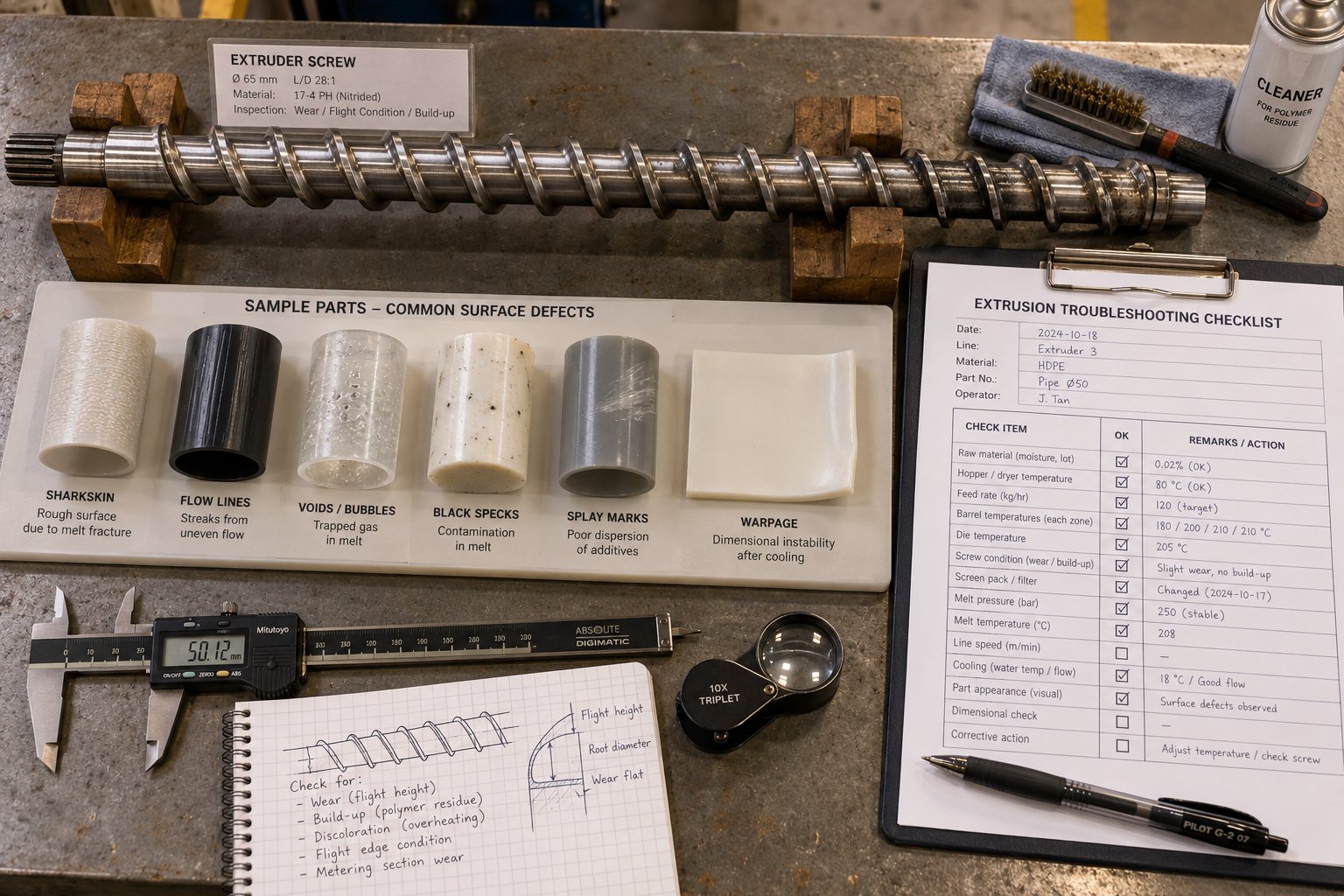
A Practical Roadmap to Solve Extruder Mixing Problems
You have identified the defect. You have classified it as dispersive, distributive, or both. You have quantified the cost. The question now is: what do you actually do — and in what order? Jumping straight to screw modifications or equipment purchases is the mistake this entire article has been building toward preventing. The corrective action sequence matters just as much as the corrective action itself, because each step either confirms or eliminates a category of root causes, narrowing the field so that every dollar you spend addresses a verified problem rather than a guess.
Step-by-Step Corrective Action Roadmap
This sequence works for both single-screw and twin-screw systems. Follow it in order — skipping steps is how plants end up replacing screws for a problem that originated in the hopper blender.
- Identify and document the primary symptom. Pull physical samples. Photograph them. Record the defect frequency — one in ten parts, one in fifty, continuous. Use the diagnostic table from Section 3 to match your dominant defect to its most probable root causes. Resist the urge to fix everything at once; anchor on the single worst symptom.
- Classify the deficiency as dispersive or distributive. Gels, fish eyes, undispersed filler clusters, and pigment specks point to dispersive failure — insufficient stress to break agglomerates. Color streaks, concentration gradients, uneven gloss, and variable additive distribution point to distributive failure — insufficient stream-splitting and spatial redistribution. If both types of defects are present, note which is dominant. This classification determines every downstream decision.
- Check upstream factors first. Before touching anything on the extruder, verify that the feed stream is consistent. Confirm blending equipment calibration, dryer dew point and material moisture levels, regrind particle size uniformity, and additive metering accuracy. Collect feed samples directly from the throat — not from storage — and test them. When an extruder is used the impression material is mixed only as well as the incoming composition allows. If the feed is inconsistent, no screw geometry or process adjustment inside the barrel can fully compensate.
- Evaluate process parameters. Review the barrel temperature profile zone by zone. Check whether the thermal profile matches the polymer's rheological needs — particularly the transition zone temperatures for semi-crystalline resins. Assess screw speed against the dispersive vs. distributive trade-off: higher speed boosts shear rate but cuts residence time. Verify back pressure by checking screen pack mesh size, breaker plate condition, and die restriction. Adjust one variable at a time and allow three to five residence times before evaluating the result.
- Assess screw and barrel condition for wear. Review trending data — output rate at reference RPM, motor amperage, specific energy consumption, and melt temperature deviation from setpoint. If these indicators show gradual degradation over recent months, measure flight clearance directly. Compare against baseline clearance values. A screw with flight clearance exceeding 0.010 inches is leaking polymer over the flights, bypassing the high-shear zone entirely, and no process parameter adjustment can restore the mixing performance that worn geometry has surrendered.
- Consider screw geometry or mixing element changes. This step comes sixth — not first — because it should only follow confirmation that upstream factors, process parameters, and mechanical condition are not the primary root causes. If the diagnosis points to dispersive deficiency, evaluate adding high-shear elements: Maddock mixers for single-screw systems, 90-degree kneading blocks or toothed mixing elements for twin-screw systems. If distributive deficiency is confirmed, consider pin mixers, cavity transfer mixers, 30-degree kneading blocks, or a downstream static extruder mixer. For twin-screw configurations, review the full element sequencing — kneading block stagger angles, zone lengths, and element placement relative to the melt front — against the guidelines from Section 5. Review whether your twin screw extruder mixing elements are correctly matched to the formulation's dispersive and distributive requirements.
- Validate improvement with measurable quality metrics. Do not rely on visual inspection alone. Measure melt flow index variability (standard deviation across samples from the same run), gel count per unit area, color deviation (Delta E values), mechanical property Cpk, and part weight consistency. Compare post-correction metrics against the pre-correction baseline you established in Step 1. Improvement that cannot be measured is improvement that cannot be sustained — the next material change or process drift will erase it, and you will be back to square one without knowing what worked.
This sequence is deliberately conservative. It prioritizes low-cost, reversible interventions — upstream checks, process parameter adjustments — before committing to hardware changes that cost time, money, and production downtime. Most plants that follow it systematically discover that their mixing problem originates in Steps 3 through 5, not Step 6. The screw gets blamed first because it is the most visible component, but it is rarely the only — or even the primary — culprit.
When Screw and Barrel Replacement Becomes the Right Solution
Sometimes, though, the screw is the problem. Two specific scenarios justify equipment-level changes rather than further process optimization:
Scenario 1: Wear-related mixing degradation is confirmed. Steps 5 and the trending analysis from Section 6 have established that flight clearances have opened beyond acceptable limits. Output at reference RPM has dropped. Melt temperature runs consistently above setpoint despite correct barrel temperatures. Specific energy consumption has shifted measurably. In this case, the screw and barrel simply cannot deliver the shear and mixing intensity they were designed for — no process parameter change can compensate for metal that is no longer there. Replacement is not optional; it is the only path back to the machine's designed mixing capability.
Scenario 2: Fundamental screw geometry is wrong for the application. The screw was designed for a different polymer, a simpler formulation, or a lower performance standard than the current application demands. A general-purpose single screw with no mixing section cannot be "tuned" into a high-performance mixing screw through process adjustments alone. A twin-screw configuration with inadequate kneading zone length or incorrect stagger angle sequencing will not suddenly deliver uniform dispersion because you changed the barrel temperature profile. The geometry itself limits the mixing ceiling, and only a redesigned screw or new mixing elements can raise it.
In both scenarios, the critical principle is the same: replacement should address the specific mixing deficiency, not simply restore identical geometry. Replacing a worn screw with an exact copy of the original design is a missed opportunity — especially if the original design lacked adequate mixing sections for the current application. A replacement screw optimized for the diagnosed mixing problem can simultaneously restore lost performance and raise the mixing ceiling beyond where it was when the original screw was new. The polymer engineering analysis from UniSol and GTS documented exactly this: one extruder running worn OEM screws designed for 4.5 tons per shift had degraded to 3.5 tons. Optimized replacement screws did not just restore the original capacity — they doubled output to 8.5 tons by tailoring the design to the actual process requirements.
Proper diagnosis must always precede equipment changes. Replacing screws without understanding the specific mixing deficiency — whether it is dispersive, distributive, wear-related, or configuration-driven — wastes resources and risks repeating the same problem with new hardware.
This is where working with screw barrel specialists who understand mixing science — not just machining tolerances — makes a measurable difference. The right partner evaluates your diagnosed mixing deficiency, your polymer and filler characteristics, your throughput requirements, and your thermal constraints before specifying a replacement geometry. For plants that have completed the diagnostic steps above and confirmed that screw barrel replacement or optimization is the correct path forward, NANHAIYA's screw barrel support provides practical assistance for extrusion plants, recycling operations, and processing teams dealing with melt-quality problems and mixing-related performance issues. Their relevance is particularly strong for recycling operations, where variable feedstock composition amplifies every mixing deficiency and demands screw designs that can handle inconsistent incoming material without sacrificing homogeneity.
The roadmap ends where it began — with the defect. If you followed the sequence, your corrective action is now targeted at a verified root cause, validated with measurable metrics, and justified by a documented business case. The mixing problem is no longer a vague complaint about "poor quality" or an instinct to blame the screw. It is a specific, diagnosed deficiency with a specific, measurable fix. That precision is what separates plants that solve mixing problems permanently from plants that chase them indefinitely.
Frequently Asked Questions About Extruder Poor Mixing Problems
1. What are the most common signs of poor mixing in an extruder?
The most recognizable signs include color streaks or swirls in the extrudate, gels and fish eyes in sheet or film, unmelted polymer particles, uneven surface gloss, variable part weight, and scattered mechanical test results across a single production lot. Inconsistent melt flow index readings from the same batch are another strong indicator. Each symptom points to a different type of mixing failure — for instance, color streaks suggest poor distributive mixing while gels indicate insufficient dispersive stress. Identifying the dominant symptom first is the most efficient way to narrow down root causes and avoid costly trial-and-error adjustments.
2. What is the difference between dispersive and distributive mixing in extrusion?
Dispersive mixing breaks down agglomerates, gels, and oversized domains by applying shear or elongational stress that exceeds the cohesive forces holding them together. It solves particle size problems. Distributive mixing, on the other hand, spatially rearranges already-sized components uniformly throughout the polymer melt through repeated splitting, reorienting, and recombining of flow streams. It solves spatial uniformity problems. The distinction matters because adding aggressive kneading blocks (a dispersive solution) will not fix color streaks (a distributive problem), and gentle stream-splitting elements will not eliminate gels. Diagnosing which type of mixing is deficient before making any changes prevents wasted time and money.
3. Why does my twin-screw extruder still produce mixing defects despite having kneading blocks?
Twin-screw extruders have superior mixing capability, but capability and actual performance are not the same thing. Common reasons for persistent defects include using the wrong kneading block stagger angle for the defect type (90-degree blocks for a distributive problem, for example), placing intense kneading elements before the polymer is fully molten, having insufficient total mixing zone length, or running process parameters that undermine the screw design. Increasing screw speed, for instance, raises shear rate but simultaneously reduces residence time — potentially worsening distributive mixing even while improving dispersive action. Scale-up from lab to production equipment can also shift shear and residence time distributions enough to reintroduce defects that were absent at smaller scale.
4. Can screw and barrel wear cause mixing problems in an extruder?
Yes, and wear is one of the most underestimated causes because it degrades mixing quality so gradually that operators adapt without realizing performance has changed. As flight clearance increases from wear, polymer leaks over the screw flights without being subjected to the high-shear scraping action that represents the primary mixing event in single-screw systems. A new screw typically has 0.002 to 0.004 inches of flight clearance, while a screw needing replacement exceeds 0.010 inches. Tracking output rate at reference RPM, motor amperage, specific energy consumption, and melt temperature deviation over time can reveal wear-related mixing degradation before direct dimensional measurements confirm it. Specialists like NANHAIYA offer screw barrel support specifically for plants experiencing progressive melt-quality decline tied to wear.
5. How do I build a business case for fixing extruder mixing problems?
Start by categorizing scrap by specific defect type rather than recording it as a single number — this reveals which mixing failure drives the largest losses. Then track rework labor hours, document customer complaint costs over 12 months, measure melt flow index variability as a process capability metric, and quantify any additive overconsumption used to compensate for poor distribution. Compare the total annual cost of these losses against the cost of the proposed corrective action, whether that is new mixing elements, a screw redesign, or upstream equipment upgrades. Most properly diagnosed mixing optimization projects achieve payback in under 12 months, with documented cases showing screw replacements paying for themselves through additive savings alone.
Written by
Nanhaiya Technical Team
Zhoushan Nanhaiya Plastic Machinery Co., Ltd.
The Nanhaiya technical team supports screw and barrel manufacturing projects through application review, technical communication, custom manufacturing coordination, and production and quality control.
Discuss Your Application
Related Articles
More insights on screw barrel technology and plastics processing.
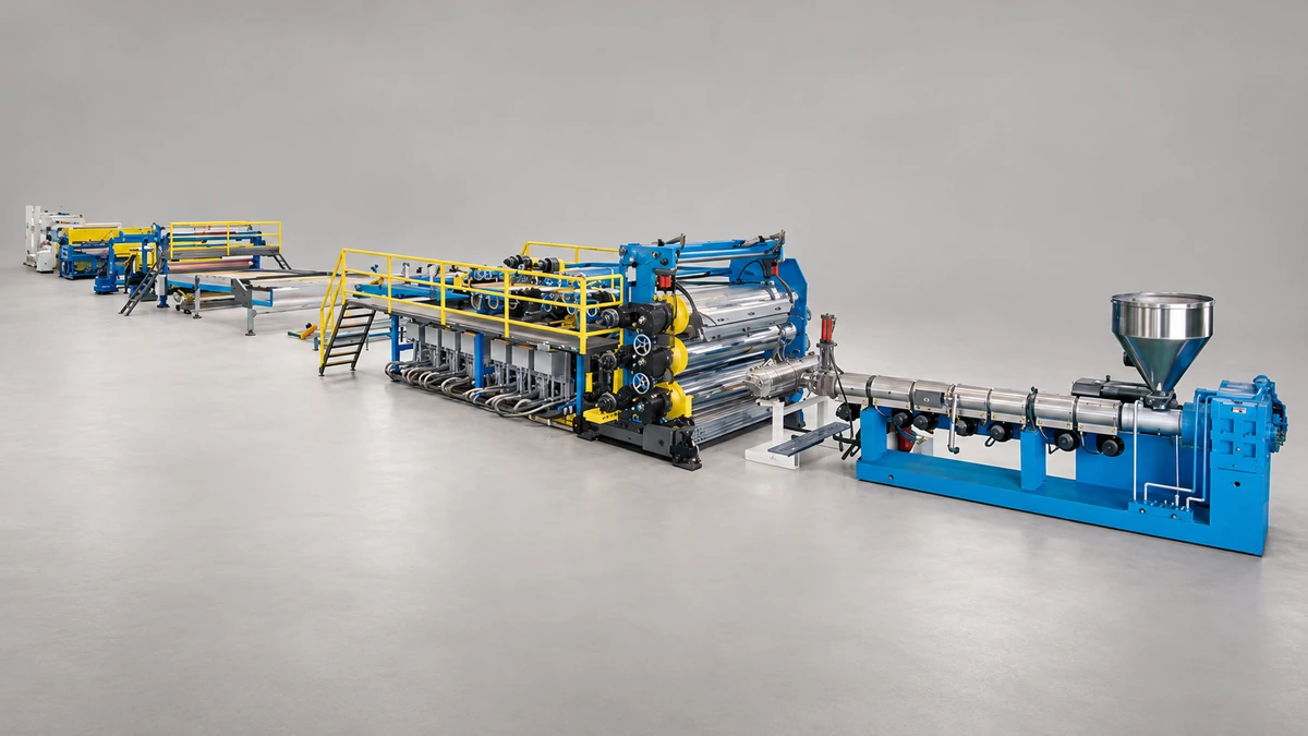
Sheet Extrusion Troubleshooting: Trace Every Defect to Its Root Cause
Nov 2, 2026
Master sheet extrusion troubleshooting with a systematic defect diagnosis framework. Fix orange peel, gauge variation, gels, flatness issues, and co-extrusion problems fast.
Read Article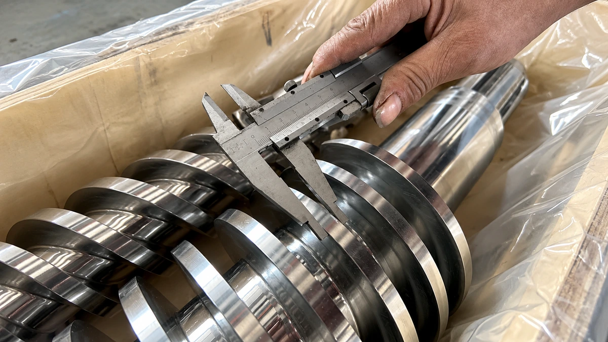
Extrusion Screw Compression Ratio: The Math Most Processors Get Wrong
Nov 2, 2026
Learn how to calculate extrusion screw compression ratio correctly, compare geometric vs. effective ratios, and match compression to every common thermoplastic.
Read Article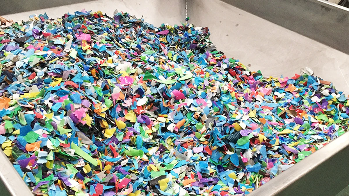
Twin Screw Extruder for Recycling: Scrap In, Sellable Resin Out
Oct 30, 2026
Learn how a twin screw extruder for recycling transforms contaminated plastic scrap into sellable pellets. Covers screw design, polymer guides, and line setup.
Read ArticleLooking for something else?
Search by material, symptom or product and jump straight to the relevant page.
These are navigation suggestions based on keyword matching — not a quotation, not a delivery commitment, and not a substitute for engineering review. Final specification is confirmed by our engineers against your drawings and processed material.
Need help with screw barrel selection?
Share your machine model, processed material and application. Our team can help with pricing and technical support.