

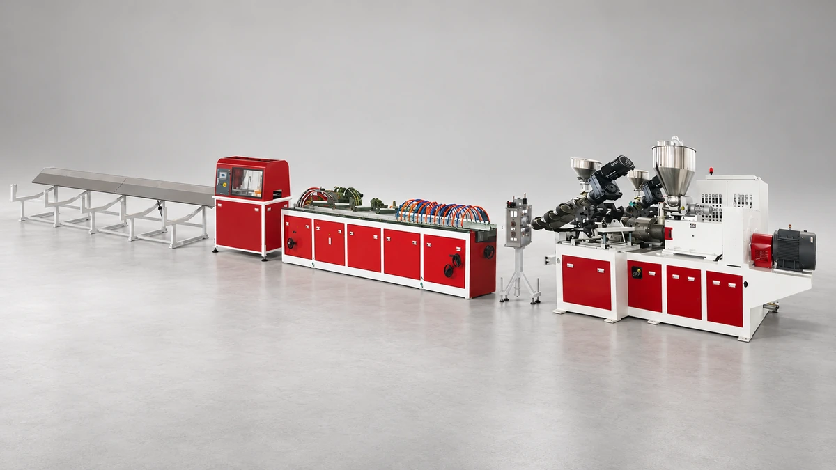
What Is a PVC Window Profile Making Machine
Imagine feeding white PVC powder into one end of a production line and watching fully formed, precision-cut window frames emerge from the other. That is exactly what this class of window machine does — and understanding how it works is the first step toward making a confident investment in one.
Defining the PVC Window Profile Making Machine
A PVC window profile making machine is an integrated extrusion production system that converts raw PVC compound into finished window profile shapes through continuous heating, melting, shaping, cooling, and cutting — all in a single automated line.
In practical terms, the system starts with a dry-blended PVC compound fed into an extruder, where rotating screws melt and homogenize the material. The molten PVC is then forced through a precision die that defines the profile's cross-section, followed by vacuum calibration, spray cooling, haul-off, and automatic cutting. Every stage operates in sync, producing consistent lengths of window framing ready for fabrication into finished windows.
Why PVC Dominates Modern Window Frame Production
PVC has earned its place as the go-to material for window frames across residential and commercial construction. The reasons are straightforward:
- Thermal insulation — Multi-chamber PVC profiles create natural air pockets that reduce heat transfer, improving building energy efficiency.
- Weather resistance — Unlike wood, PVC does not rot, warp, or corrode, even after decades of UV and moisture exposure.
- Low maintenance — There is no need for painting or sealing; a simple wipe-down keeps profiles looking new.
- Recyclability — PVC window profiles can be reprocessed multiple times, aligning with growing sustainability demands in construction.
These material advantages, combined with the speed and repeatability of modern window machining through extrusion, explain why PVC profiles dominate markets worldwide. The technology behind the production line, however, involves far more nuance than most buyers realize.
This guide walks you through every layer of that nuance. You will learn how each stage of the production chain works, what extruder configurations exist and how they differ, how to plan a factory layout around your line, and how to match the right equipment to your specific output and budget goals. Think of it as a technology-neutral roadmap — no product pitch, just the information you need to evaluate your options clearly.
The journey starts where every window profile begins: the raw PVC compound meeting the extruder's feed throat.
The Complete Production Chain Explained Step by Step
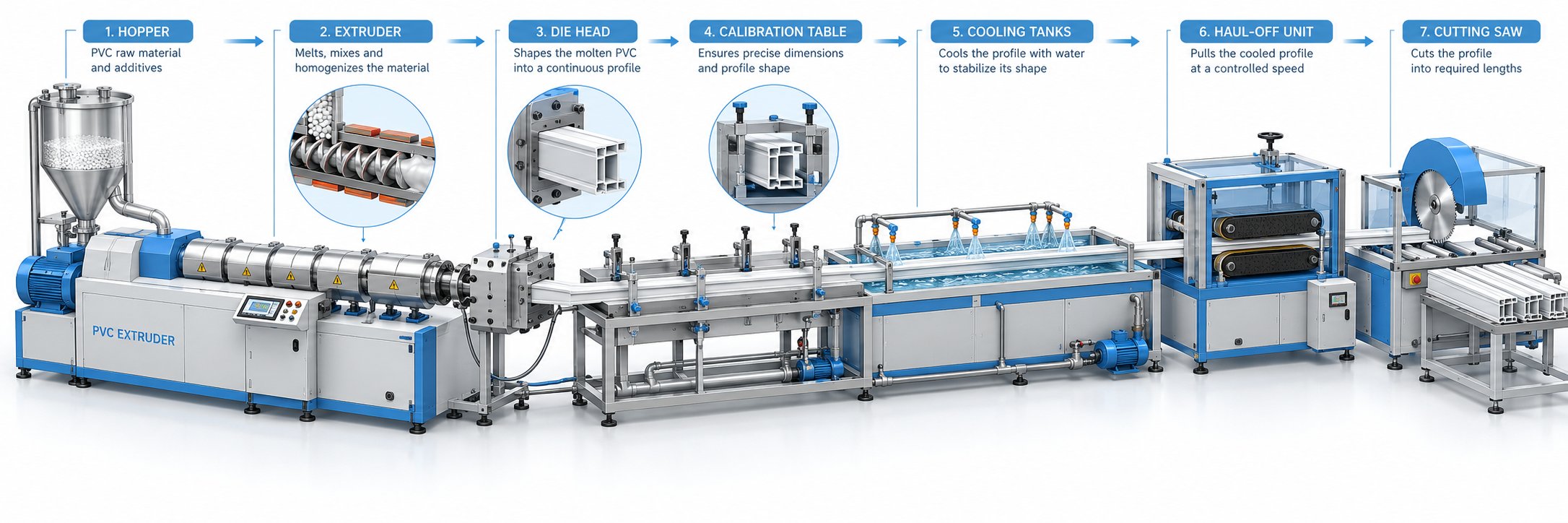
A PVC window profile making machine is not a single device — it is an entire orchestra of coordinated stations, each performing a specific task in strict sequence. Skip a beat at any point, and the final profile suffers in dimensional accuracy, surface finish, or structural integrity. Understanding how the full chain connects gives you the foundation to evaluate any production line on its real merits.
From Raw PVC Compound to Finished Profile
Picture the process as a continuous relay race. Raw PVC resin, along with stabilizers, lubricants, impact modifiers, and pigments, enters the line as a dry powder blend. Minutes later, that powder has been transformed into a rigid, multi-chamber profile cut to exact length and ready for window fabrication. Every stage feeds directly into the next with no interruption — and that seamless continuity is what makes extrusion so efficient for high-volume window manufacturing automation.
Here is the complete production sequence, from the mixing room to the stacking table:
- Dry blending and compounding — A hot/cold mixer disperses additives uniformly into the PVC resin and then cools the blend to a storage-safe temperature. Consistent blending here prevents every downstream defect, from color streaks to weak weld corners.
- Extruder feeding — The dry blend is conveyed into the extruder's feed hopper, where a metering system delivers a steady, controlled flow to the screw intake zone. Stable feeding prevents output surges that would cause dimensional variation in the finished profile.
- Melt plasticizing — Rotating screws inside the heated barrel shear, compress, and melt the powder into a homogeneous melt, typically reaching temperatures between 150 °C and 200 °C. This is the heart of the line — melt uniformity here dictates every quality attribute downstream.
- Die head shaping — The molten PVC is forced through a precision-engineered die that defines the profile's cross-sectional geometry, including internal chambers, wall thicknesses, and surface contours. Even minor imperfections in die design or flow balance show up as visible defects on the finished product.
- Vacuum calibration — Immediately after the die, the still-soft profile enters a calibration sleeve where vacuum pressure pulls it against cooled metal walls to lock in exact dimensions. This stage is where the profile earns — or loses — its dimensional tolerance.
- Spray cooling — The profile passes through one or more water spray tanks that progressively lower its temperature, solidifying the PVC throughout its full wall thickness. Tank length depends on line speed and profile complexity; thicker, multi-chamber window profiles need longer cooling residence times.
- Haul-off — A caterpillar- or belt-type pulling unit grips the cooled profile and draws it through the line at a constant speed synchronized with the extruder output. Inconsistent haul-off speed is a common root cause of warping, bowing, or weight-per-meter variation.
- Online punching or routing (optional) — Some lines include inline stations that punch drainage slots, hardware screw channels, or ventilation holes directly into the moving profile. Performing these operations inline eliminates a separate downstream fabrication step and improves throughput.
- Automatic cutting — A flying saw or planetary saw cuts the continuously moving profile to precise lengths without stopping the line. Accurate, burr-free cuts here reduce scrap and speed up downstream window assembly.
- Stacking and packaging — Cut profiles are transferred to a tilting table or automated stacker, grouped into bundles, and wrapped for storage or shipping. Proper stacking prevents surface scratches and bowing during transport.
How Each Stage Connects in a Continuous Line
Sounds complex? It is — but the critical insight is this: the extruder drives the entire line, yet it cannot compensate for weaknesses in downstream windows machinery. A perfectly plasticized melt means nothing if the calibration table cannot hold vacuum, or if the haul-off jerks at irregular intervals. Every component must be precisely matched in capacity and synchronized through closed-loop speed control.
Think of it like a highway on-ramp. The extruder sets the traffic flow rate, and every station downstream must handle that exact flow without bottlenecks or gaps. When a supplier quotes a line at 300 kg/h, that number is only meaningful if the cooling section, haul-off, and cutter can all sustain that throughput with your specific profile geometry and formulation.
This chain-level perspective is essential because it shifts the buying conversation away from extruder specs alone and toward the performance balance of the complete system. The extruder configuration, however, remains the single most consequential technical decision — and the differences between available options are more significant than most spec sheets suggest.
Single-Screw vs Twin-Screw Extruder Configurations Compared
The extruder configuration you choose shapes everything that follows — output capacity, melt quality, energy draw, and even your factory floor plan. For a pvc profile production line dedicated to window frames, three main options compete for attention: conical twin-screw, parallel twin-screw, and single-screw. Each carries distinct engineering trade-offs, and understanding those trade-offs is the difference between a line that hums for years and one that fights you every shift.
Conical Twin-Screw Extruders for Rigid PVC Profiles
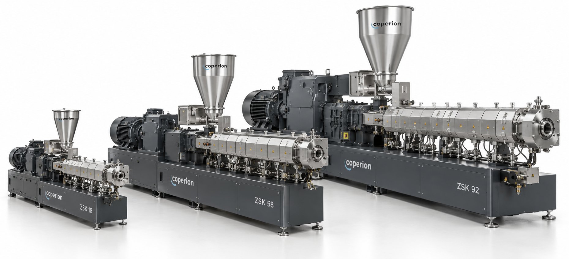
If you survey window profile factories worldwide, one configuration dominates the floor: the conical twin-screw extruder. There is a good reason for that consensus. Conical designs feature two tapered, counter-rotating screws that are wider at the feed end and narrower at the discharge end. This geometry creates a naturally large intake zone that pulls in low-bulk-density PVC dry blend without starving, while the tapering barrel progressively compresses the material as it melts — generating pressure smoothly rather than through aggressive shear spikes.
Why does that matter for PVC specifically? Rigid PVC is notoriously heat-sensitive. Push it too hard with excessive shear, and localized overheating triggers thermal degradation — releasing hydrochloric acid gas, causing discoloration, and weakening the profile's mechanical properties. Conical twin-screw extruders handle this risk better than any alternative because their intermeshing, counter-rotating screws deliver gentle yet thorough plasticizing. The result is a uniform melt with consistent gelation levels, which translates directly into profiles with smooth surfaces, tight dimensional tolerances, and reliable weld-corner strength.
Beyond processing quality, the compact footprint is a practical bonus. Because the screws taper, the gearbox and drive assembly sit behind a narrower barrel discharge, keeping the overall machine length shorter than an equivalent-output parallel design. For manufacturers planning a plastic profile production line in a space-constrained facility, that difference in floor space is meaningful.
The screw and barrel pair inside a conical twin-screw extruder is also the single most critical wear component influencing melt quality and energy efficiency. As these parts wear over thousands of operating hours, the clearance between screw flights and barrel wall increases, degrading plasticizing consistency and raising specific energy consumption. That is why sourcing precision-manufactured replacement barrels matters. Specialist suppliers like NANHAIYA, which produces custom and replacement conical twin screw barrels for PVC profile, pipe, board, and WPC extrusion lines, serve this exact need — helping manufacturers maintain stable plasticizing performance without replacing the entire extruder.
Parallel Twin-Screw and Single-Screw Alternatives
Parallel twin-screw extruders use two same-diameter screws running side by side. They offer greater freedom in screw design because uniform diameters allow engineers to stretch pitch configurations — extending the barrel from, say, 22D to 33D or even 36D — to boost throughput while preserving similar processing conditions. Industry analysis from Rollepaal highlights that advances in FEM-based gearbox design have eliminated the historical torque limitations that once made parallel machines less reliable, giving them equal longevity at high loads.
Where parallel machines truly shine is in very high output scenarios, particularly large-diameter pipe production. Their wider processing window can accommodate aggressive throughput targets more comfortably, and venting flexibility — such as adding an early vent position — helps manage moisture and volatiles at elevated speeds. However, for typical window profile outputs (roughly 80 to 300 kg/h), the extra capacity of a parallel machine often goes unused, and the larger footprint and higher gearbox cost add expense without proportional benefit.
Single-screw extruders, meanwhile, occupy a different niche entirely. With just one rotating screw inside the barrel, they rely heavily on friction and external heat to melt material. Mixing and dispersive capability are inherently limited compared to intermeshing twin-screw designs. For rigid PVC dry blends — the standard feedstock for window profiles — single-screw machines struggle to achieve the homogeneous melt quality needed for multi-chamber profiles with thin internal walls. They perform better when processing pre-compounded PVC pellets, but that adds an upstream pelletizing step and extra cost. You will occasionally see single-screw extruders on entry-level lines producing simple, thick-walled profiles, yet they are rarely the right choice for serious window frame production where industrial automation for window manufacturing demands consistency shift after shift.
Choosing the Right Configuration for Your Application
So how do you decide? The table below lays out the key differences across all three configurations, benchmarked against the factors that matter most for automated sill and track production and broader window profile extrusion:
| Feature | Conical Twin-Screw | Parallel Twin-Screw | Single-Screw |
|---|---|---|---|
| Typical output range | 80 – 350 kg/h | 200 – 800+ kg/h | 50 – 200 kg/h |
| Profile types suited | Multi-chamber window profiles, door frames, sills | Large-diameter pipes, heavy industrial profiles | Simple thick-wall profiles, pre-compounded pellets |
| Dry blend processing | Excellent — designed for PVC powder | Very good with proper screw design | Poor — requires pre-compounded pellets for best results |
| Energy efficiency | High — gentle shear reduces wasted heat | Moderate to high — depends on output utilization | Moderate — higher friction losses, more external heating |
| Maintenance complexity | Moderate — screw/barrel replacement is the key wear item | Higher — longer barrels, more complex gearbox | Low — simpler mechanics, fewer components |
| Footprint | Compact — tapered barrel shortens overall length | Larger — uniform diameter demands more floor space | Compact — but limited by output capacity |
| Best use case | Standard and high-volume PVC window profile lines | Very high throughput pipe and heavy profile applications | Entry-level lines or secondary extrusion of pelletized PVC |
For the vast majority of manufacturers building or upgrading a pvc window profile making machine line, the conical twin-screw extruder remains the safest, most proven starting point. It balances processing quality, energy efficiency, and cost in exactly the range that window profile production demands. Parallel machines enter the conversation only when throughput targets far exceed what a conical can deliver, and single-screw setups suit budget-constrained operations willing to accept narrower processing flexibility.
Whichever configuration you select, keep one principle front of mind: the extruder is only as capable as the downstream equipment it feeds. Even the finest plasticized melt will not hold shape without precision calibration, consistent cooling, and perfectly synchronized haul-off — the very components that complete the production line beyond the extruder itself.
Essential Downstream Equipment for Profile Extrusion Lines
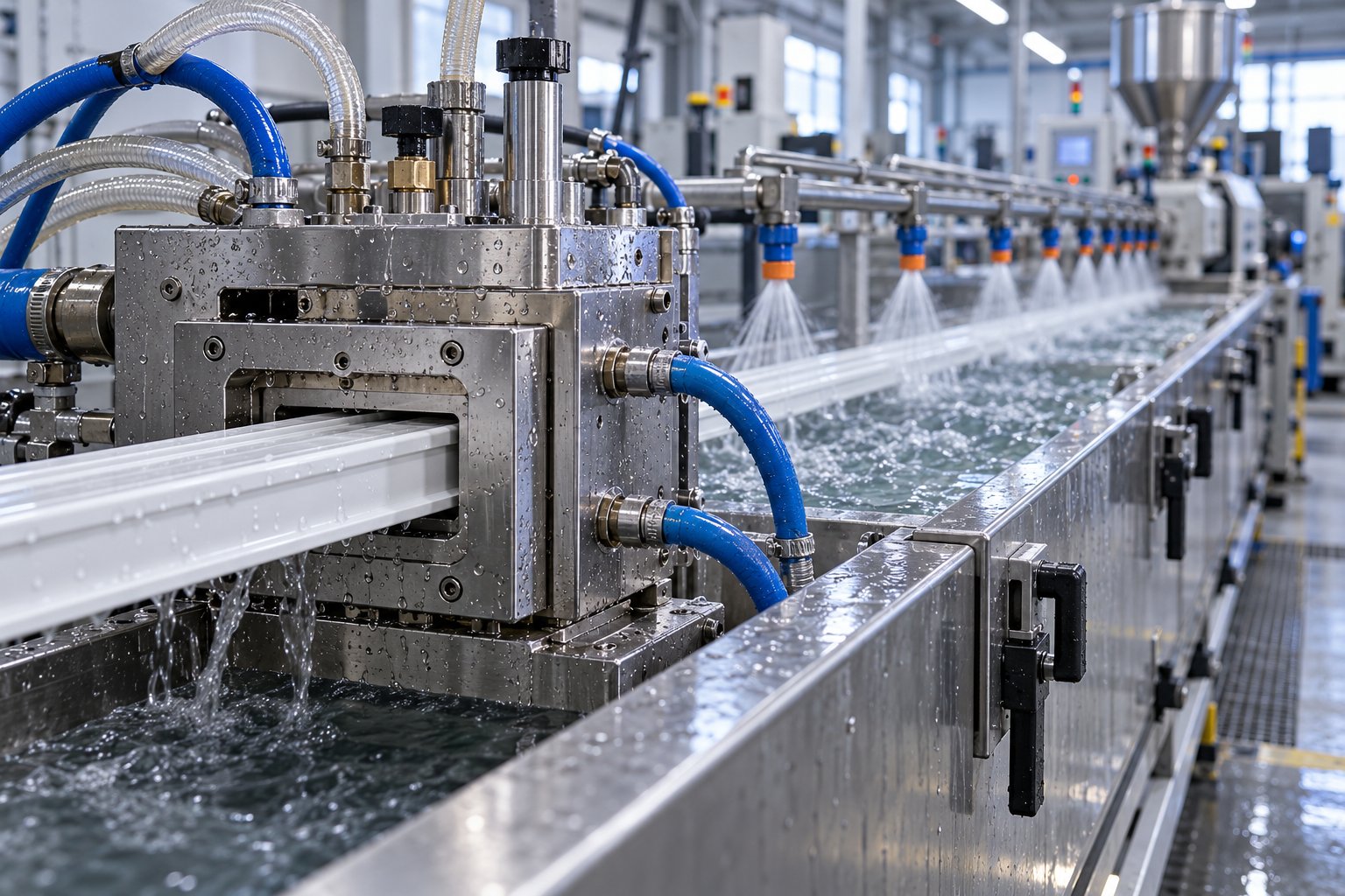
A perfectly plasticized melt exits the die as a soft, shapeable ribbon of PVC — and that is the most vulnerable moment in the entire production chain. Gravity, uneven heat loss, or the slightest pulling inconsistency can distort a multi-chamber window profile beyond tolerance before it ever reaches the cutting saw. The downstream section of your window machinery exists to prevent exactly that, turning an unstable hot shape into a rigid, dimensionally accurate profile ready for fabrication.
Every station downstream is purpose-built to solve a specific problem. Miss one, undersize another, and even the best extruder cannot save the finished product. Here is what each component does, why it matters, and what specifications to watch when evaluating window machines for your facility.
Vacuum Calibration and Cooling Systems
Imagine squeezing toothpaste from a tube — that soft, formless extrusion is roughly what PVC looks like as it leaves the die. The vacuum calibration table is the first quality gate, and arguably the most critical piece of downstream equipment on the entire line.
A vacuum calibration table uses negative pressure to pull the still-soft profile outward against precision-machined calibration plates or sleeves while cooling water simultaneously extracts heat. This combination of vacuum force and temperature control locks the profile's cross-section — including internal chambers, corner radii, and wall thicknesses — into its final geometry. The tooling inside the calibration section is profile-specific, meaning each distinct window profile shape requires its own set of calibration plates. That makes this tooling a significant upfront investment, but it is also the single factor most responsible for dimensional accuracy.
Two variables drive calibration performance: vacuum pressure and water temperature. Insufficient vacuum allows the profile to shrink away from the tooling, producing undersized dimensions. Excessive vacuum can over-expand thin walls or distort chamber geometry. Water temperature matters equally — if cooling is too aggressive near the entry, the outer skin freezes while the interior remains molten, creating internal stresses that cause post-production warping.
Following calibration, the profile passes through one or more spray cooling tanks that progressively bring it to a fully solidified state. Tank length is not arbitrary; it depends directly on your line speed and the profile's wall thickness. Thicker, multi-chamber window profiles retain internal heat longer, demanding cooling sections that may stretch 4 to 6 meters or more. Insufficient cooling length forces you to slow the line — a hidden throughput bottleneck that many first-time buyers overlook.
Haul-Off Units and Automatic Cutting Saws
The haul-off unit is the speed reference of the entire production line. Typically a caterpillar-type puller with rubber-padded belts or tracks, it grips the cooled profile and draws it through every downstream station at a constant, precisely controlled speed. As industry sources note, wall thickness depends directly on the relationship between extruder output and haul-off speed — pull faster and the profile stretches thinner; pull slower and material accumulates. Even small speed oscillations create repeating thickness patterns that compromise the profile's structural performance.
Consistent clamping pressure is just as important as speed stability. Worn caterpillar pads or uneven belt tension cause micro-slipping that shows up as weight-per-meter variation and subtle surface marks. For extrusion automation for window frames, servo-driven haul-off systems with closed-loop speed feedback have become the standard, keeping pulling speed matched to extruder output within fractions of a percent.
At the end of the line, automatic cutting saws convert the continuous profile into precise lengths. Two main technologies compete here:
- Flying saws — The saw blade travels with the moving profile on a carriage, makes the cut, then retracts to its starting position. This approach handles high line speeds well and works for most standard window profile cross-sections. Saw cutters are commonly mounted on traveling tables where the extrusion is momentarily clamped so table, saw, and profile move together during the cut.
- Planetary saws — A circular cutting wheel orbits around the profile's perimeter, splitting the material without chip removal. Planetary cutters produce exceptionally clean, square, distortion-free cuts, making them ideal for premium window profiles feeding into automated assembly. The trade-off is slower cycle time and higher equipment cost.
Both types generate some PVC dust or chips that need vacuum collection, and blade selection matters: rigid PVC cuts best at lower blade RPM to avoid chipping or cracking at the cut face.
Online Punching and Profile Stacking Systems
Between the haul-off and the cutting saw, many modern lines incorporate inline punching or routing stations. These units stamp drainage slots, hardware screw channels, and ventilation openings directly into the moving profile — eliminating a separate offline fabrication step and significantly improving throughput for automation in window extrusion manufacturing.
Here is a consolidated view of every key downstream component, its function, and the specification ranges you should evaluate:
- Vacuum calibration table — Locks profile geometry via vacuum pressure and cooling water. Look for vacuum levels of 0.02 to 0.08 MPa, independent water temperature control per zone, and stainless steel calibration tooling rated for your specific profile cross-section.
- Spray cooling tanks — Progressively solidify the profile through water spray. Typical lengths range from 3 to 6 meters per tank, with one to three tanks depending on line speed and wall thickness. Verify water flow rate, filtration, and drainage capacity.
- Caterpillar haul-off unit — Pulls the profile at constant speed through the line. Clamping force typically ranges from 500 to 5,000 N depending on profile size. Servo-driven models provide the tightest speed control for demanding tolerances.
- Online punching or routing station — Stamps or mills drainage slots and hardware channels into the moving profile. Confirm punch pattern programmability, stroke speed compatibility with line speed, and die changeover time for different profile types.
- Automatic cutting saw (flying or planetary) — Cuts the profile to length without stopping the line. Key specs include cut-length accuracy (typically ±0.5 mm), maximum cutting speed, dust extraction system, and blade type suited for rigid PVC.
- Profile stacking or tilting table — Receives cut profiles and arranges them for bundling. Automated stackers reduce manual handling, minimize surface scratches, and maintain consistent bundle sizing for logistics efficiency.
Every one of these components must be capacity-matched to your extruder's throughput and your target profile geometry. An oversized extruder paired with an undersized cooling section is a recipe for bottlenecks, just as a high-speed line paired with a manually operated stacker will choke at the very last step.
Matching these stations is one part of the equation. The degree to which they communicate and self-adjust — the line's automation level — determines whether you need an operator watching every meter of output or whether the system manages itself.
Automation Levels and Smart Manufacturing Integration
A production line with perfectly matched hardware still depends on one variable that no specification sheet fully captures: how intelligently each station talks to the others. Two factories running identical extruders, calibration tables, and cutting saws can produce dramatically different results — one holding window profiles within a fraction of a millimeter shift after shift, the other chasing dimensional drift with constant manual adjustments. The difference almost always comes down to automation level.
Understanding where your line falls on the automation spectrum — and where it should fall based on your volume targets and labor realities — is one of the most consequential decisions in planning a pvc window profile making machine investment.
Manual, Semi-Automatic, and Fully Automated Lines
Think of automation as a dial, not a switch. At one end, a basic manual line relies on operators to set barrel temperatures, adjust haul-off speed by hand, and visually judge profile quality. At the other end, a fully automated system manages every process variable through closed-loop control, logs every data point, and alerts maintenance staff before problems surface. Most real-world installations land somewhere in between.
Here is how the three tiers break down in practice:
Manual lines use standalone temperature controllers for each barrel zone, a simple variable frequency drive (VFD) for the extruder motor, and operator-set speed references for the haul-off and saw. When something drifts — melt temperature climbing, profile wall thinning, surface gloss changing — an experienced operator notices, walks to the relevant control panel, and makes a correction. Quality depends almost entirely on that operator's skill and attention span. These lines suit very small operations with limited budgets, but they carry hidden costs in scrap, rework, and shift-to-shift inconsistency.
Semi-automatic lines introduce a centralized PLC that coordinates the extruder, haul-off, and cutter under one control architecture. Barrel and die temperatures run on PID loops that hold setpoints automatically. The haul-off speed tracks the extruder output through a programmed ratio, so when an operator increases screw RPM, pulling speed follows proportionally without manual re-entry. Recipe storage lets operators recall saved parameter sets for each profile type, eliminating the guesswork of setting up a new run from memory. Semi-automatic systems represent the sweet spot for many mid-volume manufacturers — significantly better consistency than manual control, without the capital outlay of a full smart extrusion line automation package.
Fully automated lines take coordination further by closing every control loop. A PLC controlled profile extrusion system manages not just speed ratios but actively trims haul-off speed and extruder RPM based on real-time sensor feedback — melt pressure at the die head, wall thickness readings from an ultrasonic or laser gauge downstream, and weight-per-meter data from an inline scale. If the profile begins drifting slightly thick, the system nudges haul-off speed up by fractions of a percent to compensate, all without operator intervention. SCADA or HMI dashboards display every process variable on a single screen, and recipe management extends to automatic changeover sequences that ramp temperatures, speeds, and pressures to new setpoints in a controlled progression.
The operational impact is substantial. Here is a side-by-side comparison of what each automation tier delivers:
| Factor | Manual Line | Semi-Automatic Line | Fully Automated Line |
|---|---|---|---|
| Operators per shift | 3 – 5 (constant supervision) | 2 – 3 (monitoring-focused) | 1 – 2 (oversight and exception handling) |
| Throughput consistency | ±3 – 5% variation typical | ±1 – 2% with PID temperature and ratio control | ±0.5% or better with closed-loop gauge feedback |
| Typical defect rate | Higher — depends on operator vigilance | Moderate — automated temperature and speed hold reduce drift | Lowest — real-time correction catches deviations before they become defects |
| Initial investment tier | Low | Moderate | High |
| Data and traceability | Manual logbooks, no digital record | Basic parameter logging, recipe recall | Full historian with timestamped trends, alarm logs, batch traceability |
You will notice the labor savings alone can reshape the payback calculation. Reducing each shift by even one operator across three shifts adds up to meaningful annual savings — often enough to offset the premium of moving from semi-automatic to fully automated control within 18 to 24 months.
Industry 4.0 and Smart Monitoring in Profile Extrusion
Fully automated lines set the stage, but Industry 4.0 window profile manufacturing pushes the concept into an entirely different dimension. The idea is straightforward: connect every sensor, drive, and controller on the line to a network that feeds data into cloud-based analytics platforms — then use that data not just for control, but for prediction, optimization, and remote management.
What does this look like in a real profile extrusion plant? Imagine a dashboard on your tablet showing live melt pressure trends from every extruder in your factory. A gradual upward drift on Line 3 signals increasing die restriction — likely screen pack fouling or early-stage die buildup. Instead of waiting for an operator to notice degraded surface quality two hours later, the system flags the trend, estimates remaining run time before intervention is needed, and schedules the maintenance window during the next planned changeover. That is automated PVC extrusion monitoring working at its most practical level.
Several capabilities define a genuine Industry 4.0 extrusion setup:
- Real-time temperature and pressure dashboards — Every barrel zone, die zone, and melt pressure reading streams to a centralized interface. IoT-enabled extrusion platforms aggregate these parameters into cloud dashboards accessible from any location with network connectivity, enabling process engineers and quality managers to monitor remotely.
- Predictive maintenance alerts — Motor current draw, gearbox vibration signatures, and screw torque trends feed machine learning algorithms that detect degradation patterns. Rising motor load at constant RPM, for example, can indicate screw or barrel wear well before melt quality visibly suffers. Maintenance teams act on data rather than gut feeling.
- Remote diagnostics — When anomalies occur, secure connections allow equipment specialists to review live data, historical trends, and alarm logs without traveling to the plant. Resolution that once required days of on-site troubleshooting can begin within minutes.
- Dynamic process adjustment — Advanced lines use closed-loop feedback from downstream gauges to continuously trim haul-off speed and extruder RPM. The PLC expresses haul-off speed as a ratio of screw speed, and a slow gauge feedback loop adds a small correction to that ratio to hold dimensional targets — all automatically.
- Energy and OEE tracking — Per-kilogram energy consumption is logged by product and operating condition. Overall Equipment Effectiveness breakdowns — availability, performance, quality — reveal exactly where time and material are lost, shift by shift.
The integration extends beyond the production floor. Some platforms feed actual throughput and energy data directly into ERP and MES systems, replacing manual data entry with automated costing based on real consumption. For manufacturers running multiple lines or sites, multi-line comparisons highlight efficiency variations that would be invisible in plant-level averages.
Does every factory need this level of connectivity? Not necessarily. A single-line operation producing one or two profile types may find that a well-configured semi-automatic PLC system delivers all the consistency and traceability required. But for multi-line plants targeting premium markets with tight tolerances and regulatory documentation demands, smart monitoring is rapidly shifting from competitive advantage to baseline expectation.
Regardless of which automation tier fits your operation, one practical reality remains: every line — manual or smart — needs a physical home. And the way you plan the factory around it influences efficiency just as profoundly as the control system inside it.
Factory Planning and Production Line Layout Essentials
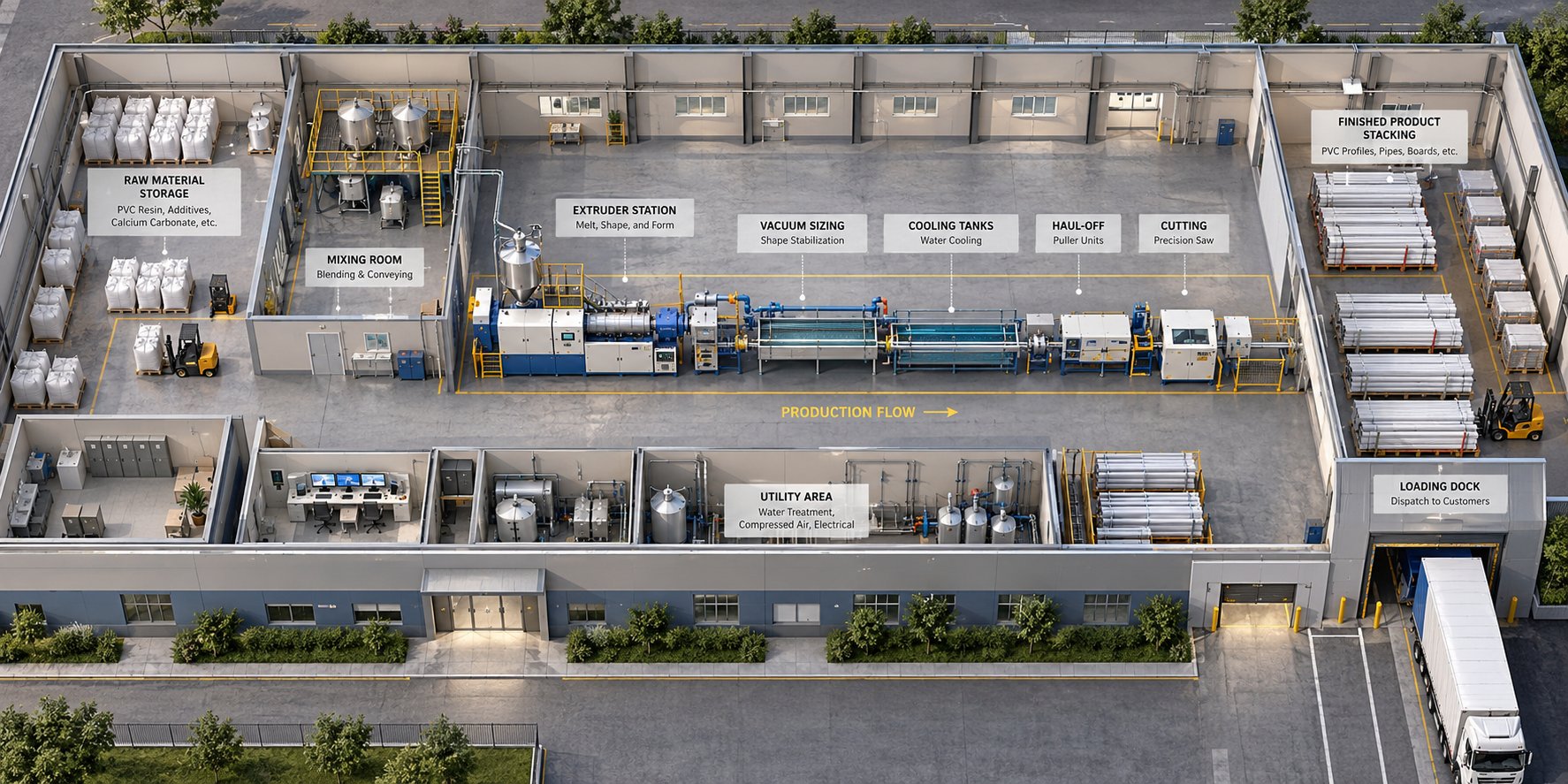
You can spec the finest extruder and the smartest controls on the market, but if the building around them is an afterthought, the line will never hit its rated output. Floor space, ceiling clearance, power capacity, cooling water, compressed air, material flow paths, and even noise management all need to be resolved before equipment arrives — not during commissioning week. PVC profile factory layout planning is where operational efficiency is either designed in or permanently compromised.
Floor Space and Line Layout Planning
A single PVC window profile extrusion line typically stretches 25 to 40 meters from the extruder feed throat to the stacking table, depending on how many cooling tanks your profile requires and whether inline punching stations are included. That figure covers only the production equipment itself. Add at least 1.5 to 2 meters of clear access on both sides for operator movement, routine maintenance, and emergency access to calibration tooling or saw blades. The result? Your extrusion hall needs a minimum clear width of about 6 to 8 meters for a single line, and significantly more if you plan to run parallel lines with shared operator walkways.
Ceiling height is easy to overlook and expensive to fix later. Overhead cranes or hoists are standard for lifting die heads, calibration assemblies, and gearboxes during maintenance. A usable clearance of 5 to 6 meters beneath any crane rail is a practical starting point, though taller profiles or stacked raw material silos may demand more. As factory planning guidance from Jiahao Machinery emphasizes, you should share a detailed workshop drawing — with clear internal dimensions, column locations, entrances, and usable height — before committing to building alterations so that the equipment supplier can verify the complete flow from raw material intake to finished-product exit.
Column placement inside the hall deserves special attention. A column that lands right where your spray cooling tank needs to sit can force an awkward line offset or a shortened cooling section — either of which costs throughput. Mark every column on your layout drawing and confirm that the uninterrupted floor zone matches the extrusion line floor space requirements for your target configuration.
Utility Infrastructure and Workflow Optimization
Three utility systems power every window profile production facility setup: electricity, cooling water, and compressed air. Undersize any of them and the line cannot run at rated capacity; oversize them carelessly and you waste capital and energy.
Electrical supply is the heaviest demand. The extruder drive motor, barrel and die heaters, vacuum pumps, haul-off servos, and the chiller collectively create a significant connected load. A representative single extrusion line — including the chiller and material handling — can carry a nameplate total in the range of 150 to 350 kW depending on extruder size, though actual demand is lower because not every component draws full power simultaneously. Applying a demand factor of 0.70 to 0.85, as utility engineering practice recommends, gives you the effective load for transformer and cable sizing. Add a 20 to 30 percent margin for motor starting surges and future expansion, and you have a realistic electrical specification to hand your site electrician.
Cooling water splits into at least two temperature tiers. The vacuum calibration table and cooling tanks need chilled process water in the 8 to 15 degree Celsius range to lock profile dimensions accurately — even a few degrees of drift shifts the solidification point and causes gauge variation. Machine-side cooling for the extruder gearbox, screw core, and oil circuits runs warmer, typically 25 to 35 degrees Celsius, where precise temperature matters less. Keeping these loops separate through a plate heat exchanger protects dimensional accuracy without forcing the chiller to overcool the entire system. Water quality matters too: hardness below 100 mg/L as CaCO3, pH between 7.5 and 8.5, and chloride below 200 ppm prevent scaling and corrosion that quietly degrade heat transfer over time.
Compressed air at 0.6 to 0.8 MPa feeds pneumatic actuators on the cutting saw, punching station, and profile stacker, as well as air knives that blow surface water off the profile after the cooling tanks. Demand is modest compared to electrical and cooling loads, but moisture or oil contamination in the air supply can mark profile surfaces — so a dryer and filter are non-negotiable. Route the compressor's cooling circuit to the machine-side water loop, never the precision chilled loop, to avoid warming the process water that controls your profile dimensions.
Beyond utilities, workflow sequencing across the facility has a direct impact on labor efficiency and material handling cost. Organize the plant so that raw material storage sits adjacent to the mixing room, the mixing room feeds directly into the extruder hopper area with minimal conveying distance, and finished profile stacking flows toward a loading dock or warehouse without crossing incoming material paths. Every unnecessary crossover or backtrack adds handling time, congestion risk, and potential for damage.
Environmental controls round out the picture. The dry-blending and mixing area generates fine PVC dust that requires a dedicated extraction system — both for worker health and to prevent powder accumulation on sensitive equipment. The extruder drive, vacuum pump, and chiller compressor are the primary noise sources on the line; positioning them away from operator stations or enclosing them reduces noise exposure. Floor drainage should handle cooling water leaks and hose bursts without pooling near electrical cabinets, and ventilation must keep the ambient temperature around drive cabinets low enough to avoid thermal derating of VFDs.
A utility infrastructure for extrusion plant checklist — covering electrical supply, cooling, compressed air, material handling, ventilation, and installation access — should be agreed with your equipment supplier before concrete is poured or cables are pulled. The table below, adapted from industry best practice, outlines the key items and what information to exchange for each:
| Utility Item | Information to Confirm |
|---|---|
| Electrical supply | Available voltage, frequency, phase arrangement; total connected load and transformer sizing with demand factor applied |
| Cooling water | Required flow, supply temperature per loop (process vs. machine), water quality and treatment needs |
| Compressed air | Required pressure (0.6 – 0.8 MPa), flow rate, air quality class, dryer and filter specification |
| Material handling | Raw material delivery method, storage capacity, conveying system to mixer and extruder hopper |
| Ventilation and extraction | Dust extraction for mixing area, cabinet cooling airflow, noise attenuation requirements |
| Installation access | Unloading, lifting, door clearances, and route to final machine position |
Getting these details right before equipment ships is the cheapest insurance against commissioning delays and chronic underperformance. It also sets the stage for a conversation that many manufacturers overlook until something breaks: the wear parts and maintenance schedules that determine whether your line keeps running at peak performance for years — or gradually drifts into expensive inefficiency.
Maintenance Schedules and Wear Parts for Long-Term Reliability
Every component on your extrusion line is aging from the moment production starts. Screws lose their flight edges, barrel bores widen, calibration sleeves erode, and haul-off pads compress — all silently, all continuously. The question is never whether these parts will wear. It is whether you catch the degradation early enough to schedule a replacement on your terms, or whether the line forces your hand with a failed profile, a customer complaint, or an unplanned shutdown that idles your entire downstream operation.
PVC extrusion wear parts maintenance is, in practical terms, the difference between a line that holds its rated output for years and one that slowly bleeds efficiency, energy, and margin. Understanding which parts wear fastest, how to recognize the early warning signs, and when to act is one of the most valuable skills a profile manufacturer can develop.
Critical Wear Parts and Their Impact on Output Quality
Not all wear parts carry equal weight. A dull saw blade costs you a few minutes to swap. A worn screw and barrel pair, by contrast, can silently degrade melt quality for weeks before the surface defects or dimensional drift become obvious — and by that point, you have already shipped questionable product and burned excess energy doing it.
Research from Plastics Technology illustrates the cost vividly: on a 100 mm extruder running polyethylene at 150 kg/h, screw wear that doubled the flight clearance forced a 13% rate reduction just to maintain acceptable discharge temperatures. Apply that math to a window profile line running three shifts, and the lost output easily justifies the cost of a proactive extruder screw and barrel replacement many times over.
Here is every critical wear component you should be tracking, along with its function, the telltale signs that it needs attention, and the maintenance action to take:
- Extruder screws and barrel — These are the highest-impact wear items on the entire line. The screws plasticize and convey the PVC melt; the barrel provides the containing bore and heat transfer surface. As the clearance between screw flights and barrel wall increases, material leaks backward over the flights instead of moving forward. You will notice higher motor current draw at the same screw speed, rising discharge temperatures, inconsistent melt pressure readings, and eventually visible surface roughness or gloss variation on the profile. Industry guidelines suggest checking screw-to-barrel clearance every two to three months for PVC lines running calcium carbonate-filled formulations, since CaCO3 is a known abrasive accelerant. A common replacement threshold is when flight clearance reaches four times the original as-new specification, though critical-tolerance window profiles may demand action at two times clearance. Keep a spare screw set in storage so the swap takes hours, not weeks.
- Die plates and flow inserts — The die defines your profile's cross-section, and any erosion or buildup on its flow channels distorts wall thickness distribution. Symptoms include uneven wall gauges, visible flow lines on the profile surface, and increasing die pressure at constant output. Apply anti-rust oil and protective film to die components during every shutdown, and inspect flow surfaces for scoring or plating wear during scheduled cleaning.
- Calibration sleeves and plates — These precision-machined tooling pieces hold the profile's final dimensions under vacuum. Wear shows up as gradual dimensional drift — profiles that slowly creep out of tolerance on specific features like chamber width or corner radii. Inspect contact surfaces monthly for grooving, and replace sleeves before tolerances exceed your specification window. Stainless steel tooling resists corrosion but still wears at the contact points where the hot profile slides through.
- Haul-off belts or pads — The caterpillar tracks or rubber pads that grip the profile compress and harden over time, reducing traction. Worn pads cause micro-slipping that creates weight-per-meter variation and subtle surface marking. Lubricate internal track gears every two weeks, adjust track tension monthly, and replace pads when grip force drops below the threshold needed for consistent pulling at your line speed.
- Saw blades — Dull or chipped blades produce rough, cracked, or angled cut faces that require rework before window assembly. Rigid PVC is particularly unforgiving — a blade that cuts cleanly on day one can chip profile edges after just a few hundred cuts if tooth geometry degrades. Inspect blades weekly, and keep spares staged for immediate changeover. Lubricate rotating assemblies and check drive belt tension monthly to maintain clean cutting action.
- Vacuum pump seals and filters — Degraded vacuum pump performance reduces the negative pressure available at the calibration table, allowing the profile to pull away from tooling and lose dimensional accuracy. Clean vacuum tank filter screens monthly and monitor vacuum level trends for gradual decline that indicates seal wear or line leaks.
Among all of these, the screw and barrel remain the dominant concern. Their condition directly controls melt homogeneity, specific energy consumption, and the stability of every quality attribute downstream. A worn barrel does not just make bad profiles — it makes the entire line work harder to produce them, driving up electricity cost per kilogram while simultaneously lowering salable output.
Preventive Maintenance Scheduling for Maximum Uptime
Reactive maintenance — running until something breaks — is the most expensive strategy in extrusion. A snapped haul-off belt or a seized vacuum pump does not just cost the replacement part; it costs every kilogram of profile you cannot produce during the unplanned stop, plus the scrap generated during restart and restabilization. Preventive maintenance for profile extrusion line operations flips that equation by scheduling interventions during planned downtime windows, often aligning them with profile changeovers or shift breaks.
A practical schedule follows a tiered structure:
- Daily — Remove dust from heating elements and electrical cabinets. Visually inspect profile surface quality for early signs of melt inconsistency. Confirm vacuum levels and cooling water temperatures are within range.
- Weekly — Clean electrical cabinet filter screens. Lubricate saw rotating assemblies. Inspect saw blade condition and cutting quality.
- Every two weeks — Lubricate haul-off track gears. Clean dust inside electrical cabinets — as maintenance guidance from LIANSU notes, roughly 80% of electrical failures trace back to poor heat dissipation caused by dust buildup.
- Monthly — Clean vacuum tank water filters. Adjust haul-off track tension. Inspect calibration tooling for wear patterns. Check drive belt tension on cutting saws. Verify cooling water quality parameters.
- Every two to three months — Measure screw-to-barrel clearance and compare against baseline values. This interval matters most for formulations containing calcium carbonate or other abrasive fillers that accelerate wear.
- Every 3,000 operating hours — Replace gearbox oil. Inspect gearbox bearings for abnormal noise or vibration signatures.
- Quarterly — Inspect mixing blade wear in the compound mixer. Check sealing gaskets on discharge valves. Review screw and barrel clearance trend data to forecast the next replacement window.
The conical twin screw barrel lifespan varies significantly depending on formulation abrasiveness, operating hours, and material quality, but a well-manufactured barrel typically outlasts the screws by a factor of roughly three. That means you may replace screws two or three times before the barrel itself needs swapping — though each clearance check should evaluate both components together, since a new screw in a worn barrel still leaves excessive clearance.
When the time comes for replacement, sourcing matters. A poorly manufactured barrel introduces dimensional inconsistencies that undermine the very melt stability you are trying to restore. Specialist manufacturers like NANHAIYA focus specifically on custom and replacement conical twin screw barrels for PVC extrusion lines — serving pipe, profile, board, foam board, and WPC producers who need barrels machined to tight tolerances for stable plasticizing performance. For window profile manufacturers running conical twin-screw extruders, having a trusted barrel supplier on speed dial means the difference between a quick, planned swap and a frantic search during an unplanned shutdown.
Proactive wear part replacement does not eliminate maintenance cost — it moves that cost from emergency budgets into planned operating expenses, where it is predictable, manageable, and far less disruptive.
Keeping a maintenance log that tracks clearance measurements, replacement dates, and motor current trends over time transforms guesswork into data-driven scheduling. You will begin to see patterns — how many operating hours your specific formulation allows before clearance doubles, which profile shapes stress calibration tooling fastest, and when seasonal cooling water temperature shifts affect dimensional stability. That historical knowledge becomes the foundation for a preventive maintenance for profile extrusion line program that truly fits your operation rather than following a generic checklist.
With your line running reliably and maintenance costs under control, the next strategic question shifts from keeping the machine healthy to choosing the right machine in the first place — matching extruder size, profile complexity, co-extrusion capability, and budget tier to your specific production goals.
How to Choose the Right Machine for Your Production Needs
You understand the production chain, you know which extruder configuration fits rigid PVC best, and you have a maintenance strategy mapped out. The remaining question is deceptively simple: which specific line configuration matches your factory, your market, and your growth trajectory? Overshoot and you burn capital on capacity that sits idle. Undershoot and you hit a throughput ceiling just as order volumes climb.
A structured PVC profile machine buyer guide boils the decision down to four interlocking factors: production volume targets, profile complexity, budget tier, and available factory space. Get these four aligned and the equipment practically selects itself.
Matching Extruder Size to Your Output Requirements
Extruder sizing is the anchor decision — everything downstream scales from it. The logic is straightforward: estimate your required daily output in kilograms, factor in planned operating hours and a realistic efficiency rate, and work backward to the kilograms-per-hour capacity your extruder needs to deliver.
Sounds simple, but two common mistakes trip up first-time buyers. The first is sizing to peak demand rather than sustained average demand, which leads to an oversized machine running chronically under load — wasting electricity and accelerating wear on components that perform best within their designed operating window. The second mistake is ignoring the difference between nameplate output and real-world output. A manufacturer may rate an extruder at 300 kg/h, but that number assumes an optimized formulation, ideal ambient conditions, and a simple profile cross-section. Your actual multi-chamber window profile, with its thin internal walls and tight tolerances, may realistically pull 220 to 250 kg/h from that same machine.
This window profile extruder size selection guide maps typical daily output targets to recommended extruder models and approximate line specifications, drawing on industry configuration data and real-world operating ranges:
| Daily Output Target | Recommended Extruder Model | Motor Power | Realistic Output Range (kg/h) | Typical Line Length | Best Suited For |
|---|---|---|---|---|---|
| 1 – 3 tonnes/day | SJSZ-51/105 or SJSZ-65/132 | 22 – 37 kW | 80 – 250 kg/h | 20 – 28 m | Small manufacturers, local market supply, startup operations |
| 3 – 6 tonnes/day | SJSZ-65/132 or SJSZ-80/156 | 37 – 55 kW | 200 – 400 kg/h | 28 – 35 m | Mid-volume producers, regional distribution, growing operations |
| 6 – 12 tonnes/day | SJSZ-80/156 or SJSZ-92/188 | 55 – 90 kW | 350 – 650 kg/h | 32 – 40 m | Large-scale manufacturers, export markets, continuous three-shift production |
| 12+ tonnes/day | Multiple lines or SJSZ-92/188+ | 90+ kW per line | 500 – 700+ kg/h per line | 35 – 40+ m per line | High-volume industrial plants, multi-line configurations |
Notice the overlap in the middle tiers. A factory targeting 4 tonnes per day could achieve that with a 65/132 machine running extended hours — or a 80/156 running a comfortable single shift with room to grow. The right choice depends on whether you value lower capital cost now or built-in headroom for the next two to three years of growth. As industry engineers emphasize, overloading a small machine destroys the gearbox, while running a large machine chronically under capacity wastes electricity — so aiming for 70 to 85 percent of the extruder's rated output during normal production is the efficiency sweet spot.
Profile Complexity and Co-Extrusion Capabilities
Output volume only tells half the story. The geometry of your target profile determines die complexity, calibration tooling investment, cooling section length, and — critically — whether a single extruder can even do the job alone.
Window profiles range from simple single-chamber glazing beads to sophisticated five- or six-chamber main frame sections with integrated gasket grooves, reinforcement cavities, and drainage channels. Each step up in complexity adds engineering demands:
- Simple profiles (glazing beads, decorative trims, small accessories) — Require relatively straightforward dies and short calibration tooling. These profiles run faster and tolerate wider process windows, making them suitable for entry-level lines or secondary production runs on a larger machine during off-peak hours.
- Standard multi-chamber profiles (casement frames, sash sections, mullions) — The workhorse of the window industry. Multi-chamber designs create the trapped air pockets that deliver thermal insulation performance. Die design becomes significantly more complex because melt must be distributed evenly across thin internal walls and multiple chambers simultaneously. Calibration tooling is profile-specific and represents a substantial tooling investment — often tens of thousands of dollars per profile shape. Cooling sections need to be longer because the internal chambers insulate the core from the cooling water, slowing heat extraction.
- Co-extruded profiles (multi-material or multi-color) — This is where the line configuration changes fundamentally. Co-extrusion technology for window profiles allows two or more materials to be processed simultaneously and fused into a single profile. A smaller secondary extruder feeds a cap layer — typically ASA or PMMA — onto the main PVC substrate as both materials converge in a specialized co-extrusion die. The outer layer provides superior UV resistance, colorfastness, or a decorative wood-grain finish without secondary laminating or painting operations.
Co-extrusion adds capital cost (the secondary extruder, co-extrusion die, and separate material handling), but it opens market segments that single-material producers simply cannot reach. In competitive markets where consumers expect colored frames, weather-resistant finishes, or sustainability features like recycled-core construction with a virgin outer skin, co-extrusion capability becomes a genuine differentiator rather than a luxury. If your business plan includes premium or export markets within the next three to five years, specifying a line with co-extrusion readiness — even if you do not activate it immediately — avoids a costly retrofit later.
Budget Tiers and Investment Planning
How do you translate all of this into a spending decision? Think of the market as three broad investment tiers, each matching a different business profile:
Entry-Level Lines
These typically pair a 51/105 or 65/132 conical twin-screw extruder with basic downstream equipment and semi-manual controls. Initial capital outlay is the lowest, and the lines suit small manufacturers supplying local or regional markets with a limited range of profile types. The trade-off is lower throughput consistency, higher labor dependency, and less room to scale without eventually replacing core equipment. For a startup testing market viability before committing to heavy automation, an entry-level line is a rational first step.
Mid-Range Lines
A 65/132 or 80/156 extruder with PLC-based semi-automatic controls, servo haul-off, and recipe storage defines the mid-range tier. These lines deliver strong throughput consistency, manageable labor requirements, and enough flexibility to run multiple profile shapes with reasonable changeover times. Most manufacturers producing standard window profile systems for domestic and regional distribution operate comfortably in this tier. It also offers a natural upgrade path — adding co-extrusion, inline punching, or smart monitoring modules as volumes grow.
High-Output Automated Lines
Built around 80/156 or 92/188 extruders with fully automated control, closed-loop dimensional feedback, co-extrusion capability, and Industry 4.0 monitoring, these lines target large-scale manufacturers running continuous three-shift operations for export or high-volume domestic markets. Initial investment is the highest, but per-kilogram production cost is the lowest — energy-efficient servo drives, minimal scrap rates, and reduced labor per tonne of output compound into significant operational savings over a 10- to 15-year machine lifecycle.
The critical insight is that the cheapest line is rarely the lowest-cost line over its lifetime. Total cost of ownership analysis consistently shows that budget equipment harbors hidden costs — higher scrap rates, greater energy consumption per kilogram, more frequent unplanned downtime, and earlier replacement cycles. Framing the purchase as a per-kilogram cost equation over 10 years, rather than a line-item capital comparison, almost always shifts the rational choice upward by one tier.
One final factor ties the other three together: physical space. Your factory footprint constrains which extruder size, cooling section length, and ancillary equipment you can actually install. A 92/188 line stretching 38 meters with dual cooling tanks, co-extrusion station, and inline punching simply will not fit in a 25-meter hall — no matter how compelling the output numbers look on paper. Revisit the floor space and layout principles covered earlier in this guide and overlay your shortlisted equipment configurations onto the actual building dimensions before signing a purchase order. A layout drawing that accounts for operator access, crane reach, utility runs, and forklift clearance is not optional — it is the final reality check that prevents expensive surprises on installation day.
Match extruder capacity to realistic daily demand, confirm your building can physically house the full line length, factor in profile complexity and co-extrusion readiness, then evaluate total cost of ownership over a decade — not just the purchase price.
With a clear framework for how to choose a PVC profile extrusion machine that fits your specific operation, the remaining question is forward-looking: what emerging technology and material trends should influence your investment decision today to keep the line competitive five or ten years from now?
Emerging Trends Shaping PVC Profile Extrusion Technology
The machine you install today will be running profiles for the next decade or longer. That means every investment decision carries an implicit bet on where the industry is heading — in raw materials, energy regulation, sustainability mandates, and processing technology. Several converging trends are already reshaping how PVC window profiles are manufactured, and buyers who account for them now will avoid costly retrofits later.
Lead-Free Formulations and Recycled PVC Processing
For decades, lead-based stabilizers dominated rigid PVC compounding because they offered excellent long-term thermal stability and wide processing windows. That era is ending. Regulatory pressure across the EU, North America, and increasingly in Asia has accelerated the shift toward calcium-zinc (Ca/Zn) stabilizer systems, which eliminate toxic heavy metals entirely. The performance trade-off is real but manageable: Ca/Zn formulations deliver good thermal stability and superior weather resistance, yet they operate within a slightly narrower processing window compared to lead-based alternatives. In practical terms, lead-free PVC stabilizer processing demands tighter barrel temperature control, more precise screw speed regulation, and closer attention to shear sensitivity — all of which favor modern PLC-controlled lines over manually operated equipment.
Running parallel to the stabilizer transition is the growing push to incorporate recycled PVC content into new profiles. Post-industrial regrind has been common for years, but post-consumer recycled PVC introduces a different challenge: variable contamination levels from labels, gasket residues, coatings, and mixed polymer traces. Advanced melt filtration systems — including laser-drilled screen disc filters capable of handling contamination levels of 3 to 5% — are making recycled PVC window profile extrusion viable at production scale. These filtration units sit between the extruder and die, continuously removing particulate contaminants while maintaining stable melt pressure. For manufacturers evaluating new lines, specifying a melt filtration station — or at least pre-engineering the floor space and plumbing connections for one — is a practical hedge against tightening recycled-content mandates in construction materials.
Energy-Efficient Drives and Next-Generation Extrusion
Energy cost per kilogram of profile is climbing the priority list for every manufacturer, and drive technology is where the biggest efficiency gains are emerging. Traditional AC induction motors, long the workhorse of extrusion lines, convert roughly 82 to 85% of electrical energy into useful mechanical output. The latest energy efficient servo driven extruder configurations — built around permanent magnet synchronous motors (PMSMs) — push that conversion efficiency to 92 to 95%. Over thousands of operating hours per year, that 10-point efficiency gap translates into meaningful electricity savings, particularly for factories running multiple lines around the clock.
Servo drives also deliver superior low-speed torque, faster dynamic response to load changes, and regenerative braking that feeds deceleration energy back into the system. Combined with real-time viscosity monitoring and adaptive screw speed control, these drives maintain optimal specific energy consumption even as formulations, ambient conditions, or profile geometries change between production runs. The future of PVC profile manufacturing increasingly belongs to lines that treat energy as a controlled process variable rather than a fixed overhead cost.
For buyers weighing their options, the takeaway is this: a line purchased with a conventional AC drive will still produce good profiles, but it will consume more energy doing so every single day of its operational life. If your facility runs two or three shifts, the payback period on servo drive upgrades is often under three years — after which the savings are pure margin improvement.
Three takeaways for any buyer evaluating a pvc window profile making machine: first, match extruder size and automation level to your realistic output targets and labor model, not to peak-case projections; second, prioritize total cost of ownership over purchase price, because energy consumption, wear part longevity, and scrap rates compound over a decade into far larger numbers than the initial equipment invoice; third, future-proof your investment by specifying lines compatible with lead-free formulations, recycled PVC processing, and energy-efficient servo drives — the regulatory and market trends driving these capabilities are accelerating, not slowing down.
Frequently Asked Questions About PVC Window Profile Making Machines
1. What is a PVC window profile making machine and how does it work?
A PVC window profile making machine is an integrated extrusion system that transforms raw PVC dry blend into finished window frame profiles through a continuous sequence of heating, melting, die shaping, vacuum calibration, cooling, haul-off, and automatic cutting. The extruder melts and homogenizes the compound, a precision die defines the profile cross-section, and downstream stations solidify and cut it to length — all synchronized in a single automated line.
2. Why is a conical twin-screw extruder preferred for PVC window profiles?
Conical twin-screw extruders are the industry standard because their tapered, counter-rotating screws provide gentle yet thorough plasticizing that suits heat-sensitive rigid PVC. The wider feed zone efficiently intakes low-bulk-density powder blends, while progressive compression avoids the shear spikes that cause thermal degradation. This results in uniform melt quality, smooth profile surfaces, and tight dimensional tolerances. Specialist suppliers like NANHAIYA manufacture precision conical twin screw barrels that help maintain stable plasticizing performance over thousands of operating hours.
3. How much factory space is needed for a PVC profile extrusion line?
A single PVC window profile extrusion line typically requires 25 to 40 meters of uninterrupted length from the extruder to the stacking table, with at least 1.5 to 2 meters of clear access on each side for maintenance and operator movement. Overall hall width should be 6 to 8 meters minimum for one line, and usable ceiling height of 5 to 6 meters is recommended to accommodate overhead cranes used during die and gearbox maintenance.
4. What are the most critical wear parts on a PVC profile extrusion line?
The extruder screw and barrel pair ranks as the highest-impact wear component, directly affecting melt homogeneity, energy efficiency, and profile surface quality. Other key wear items include die plates, calibration sleeves, haul-off belts or pads, saw blades, and vacuum pump seals. Regularly measuring screw-to-barrel clearance every two to three months and replacing components before tolerances exceed specification prevents costly unplanned downtime and quality drift.
5. How do I choose the right extruder size for my window profile production targets?
Start by estimating your required daily output in kilograms, then factor in planned operating hours and a realistic efficiency rate of 70 to 85 percent of rated capacity. For example, a factory targeting 1 to 3 tonnes per day typically suits a 51/105 or 65/132 conical twin-screw extruder, while 6 to 12 tonnes per day calls for an 80/156 or 92/188 model. Always account for the difference between nameplate output and real-world throughput with your specific multi-chamber profile geometry.
Written by
Nanhaiya Technical Team
Zhoushan Nanhaiya Plastic Machinery Co., Ltd.
The Nanhaiya technical team supports screw and barrel manufacturing projects through application review, technical communication, custom manufacturing coordination, and production and quality control.
Discuss Your Application
Related Articles
More insights on screw barrel technology and plastics processing.
PVC Conduit Pipe Extrusion Line: What No Supplier Tells You
Nov 2, 2026
Complete guide to PVC conduit pipe extrusion lines — components, extruder types, temperature profiles, defect troubleshooting, standards, and buyer decision framework.
Read Article Extrusion Line Decoded: From Screw Geometry to Factory ROI
Oct 30, 2026
Learn how an extrusion line works — from screw geometry and line configurations to automation, troubleshooting, and ROI. A complete, vendor-neutral guide.
Read Article
Sheet Extruder Machine Secrets: From Screw Design To Perfect Output
Oct 30, 2026
Learn how a sheet extruder machine works, compare line types, decode key specs, and follow a structured buyer's guide to choose the right equipment for your operation.
Read ArticleLooking for something else?
Search by material, symptom or product and jump straight to the relevant page.
These are navigation suggestions based on keyword matching — not a quotation, not a delivery commitment, and not a substitute for engineering review. Final specification is confirmed by our engineers against your drawings and processed material.
Need help with screw barrel selection?
Share your machine model, processed material and application. Our team can help with pricing and technical support.