

What Are Sink Marks in Injection Molding
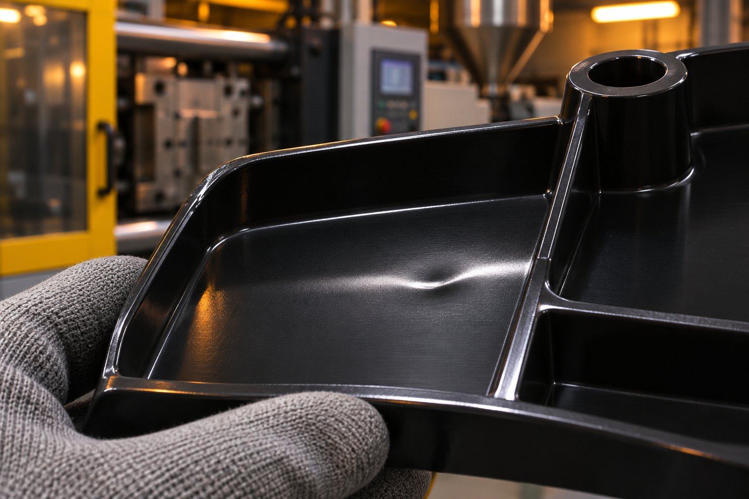
Imagine pulling a freshly molded part off the line, flipping it over, and spotting a shallow dimple right above a structural rib. The part meets every dimensional spec, yet that tiny depression signals a problem your customer will notice instantly. That dimple is a sink mark, and it ranks among the most common cosmetic defects in plastic injection molding.
Eliminating these defects rarely comes down to a single adjustment. It demands coordinated action across three intervention stages: part design, mold design, and process optimization. Each stage offers distinct leverage, and knowing where to apply force first can save weeks of trial-and-error on the press. This guide walks through the science, the design rules, the process fixes, and the measurement standards you need to address sink marks systematically, before and after steel is cut.
What Exactly Is a Sink Mark
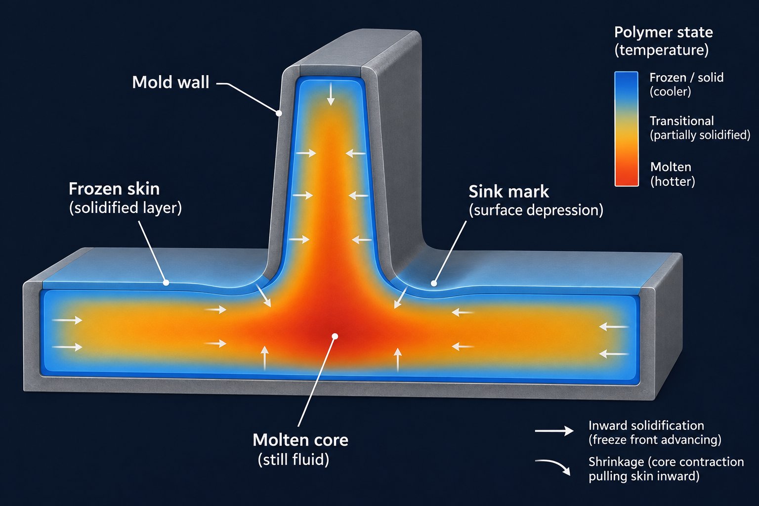
A sink mark appears as a localized, shallow depression on the surface of an injection-molded part. You'll typically find one adjacent to ribs, bosses, screw posts, or anywhere the wall cross-section thickens abruptly. During cooling, molten polymer solidifies from the mold wall inward. Thicker regions retain heat longer, and as the still-molten core contracts, it pulls the already-solidified outer skin inward, leaving a visible dent.
A sink mark is a localized surface depression on an injection-molded part caused by insufficient compensation for volumetric shrinkage in thicker regions during cooling. It forms when the solidified outer skin is pulled inward by the contracting molten core beneath it.
This distinguishes a sink mark from a purely cosmetic blemish like a scuff or a flow line. A scuff is surface-level damage; a flow line traces the path of the melt front. A sink mark, by contrast, is a structural consequence of differential shrinkage, rooted in the geometry of the part itself. Because the root cause is volumetric, the defect can appear on both textured and polished surfaces, and no amount of post-mold buffing will make it disappear.
Why Sink Marks Matter in Production
Even when a sink mark has zero impact on mechanical performance, it carries real cost. Consumer electronics housings, automotive interior trim, and medical device enclosures are all judged on surface quality the moment a customer or inspector picks them up. A visible depression signals poor quality, regardless of how well the part functions. In some cases, sink marks also compromise dimensional accuracy where mating surfaces must sit flush, turning a cosmetic issue into an assembly problem.
Material choice amplifies or softens the risk. Semi-crystalline resins like polypropylene (PP) and nylon (PA) can exhibit shrinkage rates as high as 2% or more, making them inherently more prone to sinking than amorphous alternatives such as ABS or polycarbonate, which typically shrink between 0.4% and 0.7%. Understanding this material-level behavior is the first step toward predicting where injection molding sink marks will appear, and the deeper physics behind that shrinkage is exactly where the engineering story begins.
The Science Behind Sink Mark Formation
That material-level shrinkage behavior mentioned above doesn't happen uniformly across a part's cross-section. It follows a predictable physical sequence, and understanding that sequence is the key to predicting — and preventing — sink marks in injection molding.
Volumetric Shrinkage and the Frozen-Skin Model
Picture a cross-section of a freshly filled cavity. The molten polymer touches the cold mold wall and begins solidifying almost immediately, forming a rigid "frozen skin" layer. Meanwhile, the core of the wall section remains hot and fluid. As seconds tick by, solidification marches inward from both mold surfaces, thickening the frozen skin while the molten core continues to shrink.
Here's where geometry matters. In a nominal wall section — say 2 mm thick — the core freezes relatively quickly, and the frozen skin is stiff enough to hold its shape while the modest remaining shrinkage occurs. But at a rib-wall junction or a boss base, the effective cross-section may double or triple. That thicker region retains heat far longer, so its molten core keeps contracting well after the surrounding thinner walls have fully solidified. The still-compliant skin over that thick zone gets pulled inward by the contracting core beneath it, and you're left with a visible depression — a shrink mark on the surface.
The critical takeaway is straightforward: anywhere the local wall thickness increases, cooling slows down, differential shrinkage grows, and sink risk climbs.
PVT Behavior and Material Influence
To understand why some resins sink more than others, you need a basic grasp of PVT behavior — the relationship between Pressure, Volume, and Temperature in a polymer melt.
As Plastics Technology explains, specific volume (volume per unit mass) is directly proportional to temperature but inversely proportional to pressure. During cooling inside the mold, both temperature and pressure are dropping, which means the material's specific volume is decreasing — in other words, it's shrinking. The final dimensions of the part are determined by how much total volume reduction occurs between the molten state and room temperature.
This is where resin type makes a dramatic difference. Semi-crystalline polymers like PP, PA (nylon), and POM undergo an additional volume reduction during cooling because their molecular chains organize into tightly packed crystalline structures. Amorphous polymers such as ABS, PC, and PMMA lack this crystallization step, so their total shrinkage is substantially lower. The table below illustrates the practical gap:
| Resin Family | Structure | Typical Mold Shrinkage Range | Relative Sink Mark Risk |
|---|---|---|---|
| Polypropylene (PP) | Semi-crystalline | 1.0% – 2.5% | High |
| Polyamide / Nylon (PA6, PA66) | Semi-crystalline | 0.8% – 2.0% | High |
| Polyoxymethylene (POM) | Semi-crystalline | 1.5% – 2.5% | High |
| High-Density Polyethylene (HDPE) | Semi-crystalline | 1.5% – 3.0% | High |
| ABS | Amorphous | 0.4% – 0.7% | Low to Moderate |
| Polycarbonate (PC) | Amorphous | 0.5% – 0.7% | Low to Moderate |
| PMMA (Acrylic) | Amorphous | 0.2% – 0.6% | Low |
| Polystyrene (PS) | Amorphous | 0.3% – 0.6% | Low |
A semi-crystalline resin shrinking at 2% has roughly three to four times the volumetric contraction of an amorphous resin at 0.5%. That extra contraction concentrates at thick sections, making injection moulding sink marks far more aggressive in crystalline materials — even when part geometry is identical.
The Role of Packing Pressure in Shrinkage Compensation
If shrinkage is the disease, packing pressure is the primary treatment. After the cavity fills, the molding machine continues to push additional molten polymer through the gate under sustained pressure. This extra material flows into the cavity to compensate for the volume lost as the part cools and contracts. The higher the packing pressure, the more material is forced in, and the less the surface has to collapse inward.
There's a catch, though, and it revolves around a concept called gate freeze-off. The gate — that small opening connecting the runner to the cavity — is typically the thinnest cross-section in the flow path. It solidifies before the rest of the part does. The moment the gate freezes, the cavity is sealed off from the runner system, and no additional packing material can enter the part.
This creates a critical timing window. If a thick rib base or boss hasn't received enough compensating material before the gate freezes, packing pressure becomes irrelevant — the shrinkage in that region will proceed uncompensated, and a sink mark is virtually guaranteed. Engineers use gate seal studies to identify the exact moment of freeze-off by molding parts at progressively longer hold times and tracking part weight; once weight plateaus, the gate has sealed.
The interplay between volumetric shrinkage, material type, and the packing window defines the physics of every sink mark. Yet the physics alone doesn't tell you whether that surface depression you're looking at is actually a sink mark — or something else entirely. Several defects look deceptively similar, and misdiagnosis leads to wasted corrective effort.
Sink Marks vs. Related Defects and How to Tell Them Apart
A depression on a molded part doesn't automatically mean you're dealing with a sink mark. Several injection molding defects share a similar visual signature, and jumping to the wrong diagnosis sends corrective effort in entirely the wrong direction. Before adjusting a single process parameter, it pays to confirm what you're actually looking at.
Sink Marks vs. Voids
Here's an insight that surprises many newer engineers: sink marks and voids are two outcomes of the same physical phenomenon — volumetric shrinkage in thick sections. The difference lies in the stiffness of the frozen skin at the moment the core contracts.
When the outer skin is still warm and compliant, the contracting core pulls it inward, producing a visible sink mark on the surface. When that skin has already cooled into a rigid shell, it resists deformation, and the shrinkage manifests as a hollow vacuum void trapped inside the part. Think of it as a tug-of-war: soft skin means the surface loses and collapses; hard skin means the interior loses and pulls apart.
This relationship creates a practical trade-off. Increasing packing pressure can push a void toward the surface, converting it into a shallow sink mark. Conversely, lowering mold temperature to stiffen the skin faster may eliminate a surface sink — only to reveal an internal void on a cross-section cut. Neither outcome is universally better; the right choice depends on whether cosmetic appearance or internal structural integrity takes priority for that particular feature.
Sink Marks vs. Warpage
Both sink marks and warpage stem from non-uniform shrinkage, yet they operate at completely different scales. A sink mark in injection molding is a localized depression — typically a few tenths of a millimeter deep and confined to the area directly above a rib or boss. Warpage, on the other hand, is a global distortion: the entire part bows, twists, or curves because shrinkage differs between regions, between mold halves, or along versus across fiber orientation in filled resins.
The danger here is that aggressively correcting one defect can trigger the other. Cranking packing pressure high enough to flatten every sink mark can generate residual stress gradients that warp the part after ejection. Extending cooling time to lock in the surface shape may create a temperature asymmetry between the core and cavity sides of the mold, producing a bow toward the hotter side. Effective troubleshooting treats these two defects as linked variables, not independent problems.
Sink Marks vs. Flow Marks and Surface Depressions
Flow marks in injection molding are wavy or streaked patterns on the surface caused by the melt front hesitating, slowing, or changing direction during fill. They follow the flow path and tend to appear near gates or where the wall thickness transitions abruptly. Unlike a sink mark — which forms after fill, during cooling — a flow mark is locked into the surface during fill and cannot be resolved by packing adjustments alone.
Surface depressions caused by ejection damage or mold defects add another layer of confusion. A dented ejector-pin witness mark or a depression from a worn cavity insert can mimic the appearance of sink marks in injection moulding, yet the root cause is purely mechanical. The telltale clue: ejection-related depressions align with pin locations and appear consistently in the same spot from shot to shot, regardless of process changes.
The table below provides a quick differential-diagnosis matrix to help you classify what you see before you start turning dials:
| Defect | Typical Appearance | Location Pattern | Primary Root Cause | First Corrective Action |
|---|---|---|---|---|
| Sink Mark | Shallow, smooth depression | Opposite ribs, bosses, thick sections | Volumetric shrinkage in thick regions during cooling | Verify packing pressure and gate seal time |
| Void | Not visible externally; internal hollow detected via cross-section or CT scan | Center of thick wall sections | Volumetric shrinkage when skin is too rigid to collapse | Increase pack pressure; evaluate coring out thick sections |
| Warpage | Global bowing, twisting, or curvature of the entire part | Across large flat areas or long spans | Non-uniform shrinkage from temperature asymmetry, fiber orientation, or geometry | Check mold temperature balance; review gate location for filled resins |
| Flow Mark | Wavy lines, streaks, or dull bands following the flow path | Near gate or at wall-thickness transitions | Flow-front hesitation, fountain flow effects, or low melt/mold temperature | Increase injection speed or melt temperature to maintain a consistent flow front |
| Ejection Depression | Circular or pin-shaped dent, often with sharp edges | Aligned with ejector-pin or lifter locations | Mechanical force on soft part during ejection, or worn mold component | Extend cooling time; inspect ejector pins and cavity surfaces |
Getting the diagnosis right on the first attempt saves real money. A molder who mistakes a flow mark for a sink mark injection molding defect will chase packing-pressure changes that never address the actual fill-phase issue. Likewise, confusing a void with a sink mark can lead to cosmetic fixes that leave a hidden structural weakness inside the part.
With a clear identification in hand, the next logical question shifts from what is it to how do I prevent it at the source — and that conversation starts at the CAD screen, long before any resin reaches the barrel.
Design Rules That Prevent Sink Marks Before Tooling Begins
Every sink mark you see on a finished part was baked into the geometry months earlier, at the CAD stage. Process tweaks and mold cooling tricks can reduce severity, but they're always fighting a part design that stacks the odds against them. Effective sink mark prevention part design means applying quantitative design-for-manufacturability (DFM) rules to every feature that creates a local thickness increase — ribs, bosses, screw posts, gussets, and wall transitions. Get these ratios right, and the molder has a fighting chance. Get them wrong, and no amount of packing pressure will save the cosmetic surface.
Rib and Wall Thickness Ratios
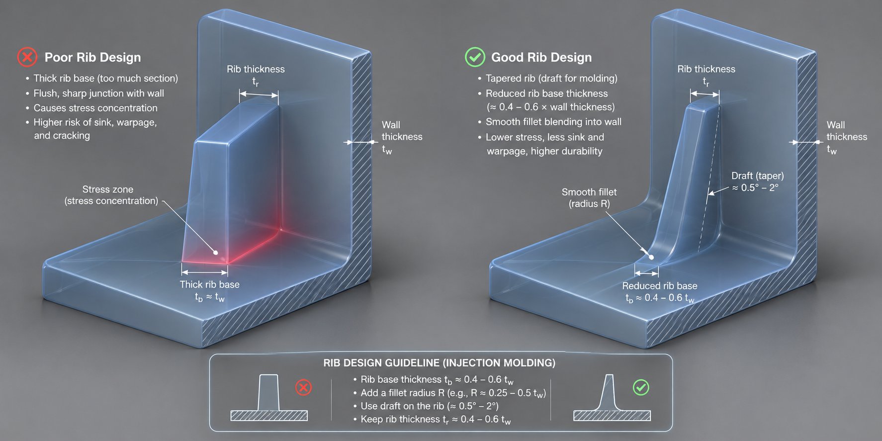
The single most referenced DFM guideline in injection molding is the wall thickness ratio for ribs. The rule is simple: the base of a rib should not exceed 50–60% of the nominal wall thickness for cosmetic parts. Why? Because the junction where a rib meets the wall creates a locally thicker cross-section. That extra mass cools slower than the surrounding wall, and the differential shrinkage pulls the opposite surface inward — producing the classic sink mark directly opposite the rib.
Resin type sharpens this rule further. Komaspec's DFM guidance recommends keeping the rib base at 40–50% of wall thickness for semi-crystalline resins like PP, PE, and POM, since their higher shrinkage rates punish thick junctions more aggressively. Amorphous materials such as ABS and PC are more forgiving, tolerating ratios up to 60%.
Thickness isn't the only lever. Tapering a rib toward its tip reduces the mass concentration at the base, where sinking originates. Additional injection molding rib design sink marks guidelines include:
- Height: No more than 3× the rib's own thickness. Taller ribs buckle under load, resist fill at the tip, and are harder to vent.
- Spacing: At least 2× the nominal wall between adjacent ribs, so the steel between them can be cooled effectively.
- Base fillet radius: 0.25–0.5× the rib thickness. A fillet reduces stress concentration at the junction, but oversizing it adds mass and reintroduces sink risk.
- Draft: A minimum of 0.5–1° per side for clean ejection without drag marks.
The table below consolidates DFM guidelines injection molding sink marks rules across all common feature types, giving you a single reference to check your design against before releasing it for tooling:
| Feature Type | Recommended Thickness Ratio (% of Nominal Wall) | Common Violation | Sink Risk Level |
|---|---|---|---|
| Ribs (amorphous resin) | 50–60% | Full wall-thickness ribs at base | High if exceeded |
| Ribs (semi-crystalline resin) | 40–50% | Same base thickness as nominal wall | Very High if exceeded |
| Bosses | Boss wall ≈ 60% of nominal wall; OD ≈ 2.0–2.4× screw diameter | Boss fused directly into sidewall, creating merged thick section | High |
| Screw Posts | Wall ≈ 60% of nominal; core from base | Solid (uncored) post behind cosmetic surface | High |
| Snap Fits | Base ≤ 60% of nominal wall | Overly thick cantilever root | Moderate to High |
| Gussets | 50–60% of nominal wall; height ≤ 2× gusset thickness | Full-thickness gusset connecting boss to sidewall | Moderate |
| Wall Transitions | Taper over ≥ 3× wall thickness; limit change to 25% per transition | Abrupt step from thin to thick section | High at the step |
Boss and Screw Post Design
Bosses are among the most frequent sources of sink marks, largely because designers default to fusing them directly into an adjacent sidewall. That solid intersection creates a massive thick section that behaves like a heat reservoir during cooling. The fix is structural: stand the boss off from the wall and connect it back with thin gusset ribs that follow the same 50–60% thickness rule.
RapidDirect's screw boss design guide reinforces this approach — size the boss outer diameter at roughly 2.0–2.4× the screw's major diameter, keep the boss wall near 60% of the nominal wall, and always core the boss from the base so the cross-section stays thin. When a boss sits directly behind a cosmetic A-surface, you have two options: core the back of that surface to reduce the effective thickness, or specify a surface texture deep enough to mask the expected sink depth. Either decision is far cheaper to make during a design review than to discover during first-article inspection.
For screw posts that must handle repeated threading, consider insert molding with metal threaded inserts rather than relying on the plastic boss alone. This doesn't eliminate the sink mark concern at the junction — you still need to manage the wall thickness ratio — but it does prevent the cracking and thread stripping that occur when a too-thick boss is trimmed down to meet cosmetic requirements.
Wall Transitions and Gate Placement
When a part requires different wall thicknesses in different regions — a structural mounting flange meeting a thin enclosure wall, for example — the transition between them is a sink-mark hotspot. Abrupt steps concentrate shrinkage right at the boundary. The DFM rule is to taper the transition gradually, spanning at least three times the nominal wall thickness, and to limit the thickness change to no more than about 25% per step. This spreads the differential cooling over a wider area, reducing the peak shrinkage at any single point.
Gate placement ties directly into this. Wise Plastics' gate placement analysis highlights a principle that every molder knows but not every designer follows: gate into the thickest section and let material flow from thick to thin. If you gate into a thin region, that thin gate area freezes off first, sealing the cavity before packing pressure can reach the heavy section downstream. The result is an uncompensated thick zone and a sink mark you cannot eliminate with process changes.
This is exactly why gate location belongs in the design conversation, not just the mold-build conversation. Choosing a gate that provides the shortest, most direct flow path to the thickest feature maximizes the packing window — the time between fill and gate freeze-off during which compensating material can still enter the cavity.
Simulation tools like Autodesk Moldflow, SolidWorks Plastics, and Moldex3D make this analysis practical long before anyone cuts steel. These platforms model fill patterns, predict gate freeze-off timing, and estimate sink mark depth at every point on the part surface. Running a fill-and-pack simulation during the design phase lets you iterate on rib thickness, boss placement, and gate location in software — where a change costs an afternoon of CAD work — rather than in hardened tool steel, where the same change costs weeks and thousands of dollars.
Sound design rules dramatically reduce the opportunity for sink marks to form. Yet the mold itself introduces another layer of variables — cooling channel layout, gate type, runner balance — that can either reinforce those design decisions or quietly undermine them.
Mold Design Strategies for Sink Mark Reduction
A part designed with textbook rib ratios and perfect wall transitions can still develop sink marks if the mold can't extract heat evenly or deliver packing pressure where it's needed most. The mold is the intermediary between smart design intent and real-world thermodynamics, and two systems within it carry the most influence over sink depth: the cooling circuit layout and the gate-and-runner configuration.
Cooling Channel Design for Thick Sections
Recall that sink marks form because thick sections cool slower than surrounding thin walls. If you can speed up heat extraction specifically at those thick zones — a rib base, a boss root, a screw-post junction — you shrink the temperature gap between thick and thin regions, and the differential shrinkage that creates the depression drops right along with it.
Traditional gun-drilled cooling lines run in straight paths dictated by the limits of conventional machining. They work fine for flat, uniform geometries, but they can't follow the contours of a complex core or wrap around a cluster of bosses. That's where targeted cooling hardware comes in:
- Conformal cooling channels: Built through metal additive manufacturing (DMLS or SLM), these channels follow the exact contour of the part surface. By maintaining a consistent wall thickness between the channel and the cavity surface, they eliminate hot spots that straight-drilled lines inevitably leave behind. Research and field applications show conformal cooling can cut cycle times by 10–40% while simultaneously improving surface quality — including measurable conformal cooling sink mark reduction at rib intersections and thick transitions.
- Baffles and bubblers: When additive tooling isn't in the budget, baffles (flat blades inserted into drilled holes to force coolant up one side and down the other) and bubblers (tubes that spray coolant against the end of a blind hole) bring cooling closer to deep cores and tall bosses that straight channels can't reach.
- Heat pipes: Sealed copper tubes filled with a phase-change fluid that rapidly transfers heat away from isolated hot spots. They're particularly useful inside slender core pins where there's no room for a water line.
Independent cooling circuits add another layer of control. Connecting a thick-section region to its own dedicated circuit — with its own flow rate and temperature setpoint — lets you pull heat aggressively from the sink-prone zone without over-cooling adjacent thin walls and risking premature freeze-off or excessive residual stress there. Even a modest 5–10 °C reduction in mold-surface temperature near a rib base can measurably reduce sink depth, because the frozen skin forms faster and becomes rigid enough to resist the inward pull of the contracting core.
The key principle behind effective mold cooling design sink marks prevention is straightforward: cool the thick sections at approximately the same rate as the thin ones. Uniform solidification means uniform shrinkage, and uniform shrinkage means no localized depressions.
Gate Type, Size, and Location Strategy
Cooling addresses the thermal side of the equation. Gate design injection molding sink marks prevention addresses the pressure side — specifically, how long and how effectively packing pressure can push compensating material into the cavity before the gate solidifies.
Every gate type creates a different freeze-off profile, and that profile directly determines your packing window:
- Edge gate: One of the most common cold-runner gate types, placed on the parting line at the side of the part. Its cross-section is relatively easy to size, and it works with almost any part geometry. However, if undersized, it freezes off early, cutting the packing window short.
- Submarine (tunnel) gate: Enters below the parting line and shears automatically during ejection. It's excellent for high-volume small parts, but its tapered, narrow profile tends to freeze faster than an edge gate of equivalent flow area, which can limit packing to thick downstream features.
- Pin gate: A small-diameter gate used in three-plate or hot-runner molds. Clean gate vestige, minimal cosmetic impact — but the tiny cross-section freezes quickly, making it a poor choice when the part has heavy sections that need sustained packing.
- Valve gate: A hot-runner gate with a mechanically actuated pin that opens and closes on command. This is the gold standard for valve gate packing pressure sink marks control because it decouples gate timing from thermal freeze-off. You decide exactly when the gate opens and closes, so you can hold the gate open long enough for full packing regardless of how thick or thin the gate orifice is.
A general sizing principle applies across all types: a larger gate cross-section delays freeze-off, extending the window during which additional melt can compensate for volumetric shrinkage. When sink marks persist despite adequate packing pressure at the machine, the gate may simply be freezing before that pressure can do its job. Increasing gate diameter or switching to a valve gate often resolves the issue without touching a single process parameter.
Gate location reinforces the design-stage rule discussed earlier — gate into or very near the thickest section. From a mold-design perspective, this sometimes means adding a secondary gate or repositioning a runner drop, which requires rebalancing the rest of the runner system.
That brings up a critical point for multi-cavity molds. Even a geometrically symmetrical runner layout can produce unbalanced filling because of non-uniform melt temperature distribution caused by shear heating along runner walls. Hotter melt flows faster, so inner cavities may fill and pack differently than outer ones. The result is inconsistent sink mark severity across cavities — some parts look perfect while others from the same shot show visible depressions. Solutions include melt-rotation inserts at runner splits, valve-gate sequencing for independent cavity control, and advanced simulation to map temperature profiles before the runner system is finalized.
Venting Considerations
Venting rarely headlines a sink-mark discussion, but it deserves a footnote with teeth. When trapped air or gas can't escape the cavity fast enough during fill, it creates localized back pressure that resists complete cavity packing. The machine's pressure gauge may read an adequate pack setpoint, yet the actual pressure at the end of fill — where the vent should be — falls short because compressed gas is pushing back. The part appears fully packed on paper but remains slightly under-packed in practice, and the resulting volumetric deficit shows up as a shallow sink mark.
The fix is mechanical: verify vent depth and location, especially at last-fill areas opposite the gate. Clean vents regularly, because even a thin film of residue or flash can reduce effective vent area enough to raise cavity pressure and starve the pack phase.
Mold-side interventions — cooling layout, gate strategy, runner balance, and venting — set the physical stage. Yet even a perfectly designed and built mold relies on the process to deliver the right pressure, temperature, and timing at every point in the cycle. When sink marks survive sound design and sound tooling, the process parameters themselves become the next lever to pull.

How to Fix Sink Marks in Injection Molding Through Process Parameter Optimization
Design sets the ceiling. Mold construction sets the floor. But between those two boundaries, the injection molding process parameters you dial in at the press determine whether a part walks out clean or carries a visible depression. Process optimization is also the fastest, cheapest corrective path available — no steel cutting, no CAD revision, just data-driven adjustment on the machine you already have. That makes it the logical first response when sink marks appear on parts molded from a proven tool.
Packing Pressure and Hold Time Optimization
Packing pressure is your most direct lever against sink marks. Here's why: as the molten core contracts during cooling, it tries to pull the solidified outer skin inward. Packing pressure counteracts that pull by forcing additional melt into the cavity, replenishing the volume lost to shrinkage. The higher the effective packing pressure at the thick section, the less the surface collapses.
Hold time governs how long that packing pressure stays active. If hold time is too short, the screw retracts before the gate solidifies, and molten resin can actually flow back out of the cavity through the still-open gate — a phenomenon known as backflow. Industry data shows that setting hold time at the exact gate-freeze edge virtually guarantees intermittent unsealed gates under normal thermal fluctuation. A safety margin of roughly 20% beyond the identified gate-seal point is standard practice for cold-runner molds.
The challenge is finding the right combination without overshooting into flash, warpage, or excessive residual stress. A structured hold time optimization sink marks sequence removes the guesswork:
- Run a gate-seal study. Mold parts at incrementally increasing hold times while keeping all other parameters constant. Weigh three consecutive shots at each increment. When part weight plateaus, the gate has frozen — that's your minimum effective hold time.
- Add a safety margin. Set hold time approximately 1–2 seconds (or ~20%) above the plateau point to buffer against normal process variation — lot-to-lot viscosity shifts, seasonal temperature swings, and minor machine drift.
- Incrementally raise packing pressure. Starting from your current setpoint, increase pack pressure in small steps (50–100 psi plastic pressure per step). After each increment, measure part weight and visually inspect sink depth. Part weight should rise with each step until it, too, plateaus.
- Monitor for side effects. At each step, check for flash at the parting line, difficulty ejecting, or emerging warpage. If any appear before sink marks disappear, you've reached the process limit and need to look upstream at mold or design factors.
- Lock the validated window. Document the final pack pressure and hold time as your process baseline. Revalidate whenever the mold moves to a different press, the resin lot changes, or plasticizing components are replaced.
Cooling Time, Melt Temperature, and Mold Temperature Effects
Packing pressure and hold time get the headlines, but the thermal parameters shape the environment in which packing either succeeds or falls short.
Cooling time determines how rigid the frozen skin becomes before internal shrinkage exerts its pull. Extending cooling time gives the skin more time to solidify and stiffen, making it harder for the contracting core to deform. The trade-off is cycle time — every added second multiplies across thousands of shots. Fictiv's process parameter guide notes that cooling accounts for 60–70% of the total cycle, so even small adjustments here carry significant throughput implications.
Melt temperature pulls in two opposing directions. A hotter melt flows more easily, transmitting packing pressure deeper into the cavity and around corners — good for reaching thick sections far from the gate. But a hotter melt also carries more thermal energy, which means greater total volumetric shrinkage as it cools to room temperature. The net effect depends on part geometry: for long, thin flow paths to a distant thick section, a moderate melt-temperature increase often helps; for parts where the thick section is near the gate, the extra shrinkage may outweigh the packing benefit.
Mold temperature follows a similar balancing act. Raising mold temperature keeps the melt fluid longer, improving packing transmission and surface replication. But it also slows solidification of the frozen skin, leaving it compliant and more susceptible to being pulled inward. For cosmetic parts in semi-crystalline resins, a slightly elevated mold temperature combined with higher pack pressure often yields the best compromise.
The matrix below maps each injection molding process parameters sink marks adjustment, its expected effect, potential side effects, and a priority ranking to guide your optimization sequence:
| Parameter | Direction of Change | Effect on Sink Marks | Potential Side Effects | Priority |
|---|---|---|---|---|
| Packing Pressure | Increase | Directly compensates volumetric shrinkage; reduces sink depth | Flash, increased residual stress, warpage, difficult ejection | 1 — Adjust first |
| Hold Time | Increase (to gate seal + margin) | Ensures packing pressure remains active until gate freezes | Longer cycle time if not offset by cooling reduction | 2 — Validate via gate-seal study |
| Cooling Time | Increase | Stiffens skin before core shrinkage can pull it inward | Longer cycle time, potential over-cooling of thin sections | 3 — Adjust after packing is optimized |
| Melt Temperature | Moderate increase | Improves packing transmission to distant thick sections | Higher total shrinkage, risk of degradation, longer cooling needed | 4 — Fine-tune carefully |
| Mold Temperature | Moderate increase | Keeps melt fluid longer for better pack; improves surface finish | Slower skin formation, longer cycle, possible warpage | 5 — Balance with cooling capacity |
| Injection Speed | Increase | Reduces premature freeze-off during fill, ensuring uniform cavity pressure at pack switchover | Shear heating, jetting, burn marks, trapped gas | 6 — Adjust only if fill pattern is uneven |
Work down the priority column from top to bottom. Packing pressure and hold time resolve the majority of process-induced sink marks. The thermal parameters are refinement levers — useful for closing the last gap, but less effective as standalone fixes.
When Process Alone Cannot Compensate
Sometimes you've optimized every parameter in the table above, and the sink mark persists. That's a signal that a physical constraint is blocking the process from doing its job. Three scenarios appear most often:
- Gate freezes too early. If the gate cross-section is too small or located far from the thick section, it solidifies before adequate packing material reaches the shrinkage zone. No amount of increased pack pressure helps once the gate is sealed. The fix lives in the mold — enlarge the gate, reposition it, or switch to a valve-gate system.
- Machine cannot sustain required packing pressure. Older or undersized machines may hit hydraulic pressure limits before delivering enough plastic pressure to compensate for high-shrinkage resins. Verifying that the machine's intensification ratio and available hydraulic pressure can generate the required plastic pressure is a basic but frequently overlooked check. Pressure loss studies from the nozzle tip through the sprue, runner, and gate can reveal where pressure is being consumed before it reaches the cavity.
- Worn plasticizing hardware delivers inconsistent melt. This is the subtlest failure mode. A screw with worn flight lands, a check ring that no longer seats cleanly, or a barrel with internal wear allows molten resin to slip backward during the packing phase instead of flowing into the cavity. The machine's pressure transducer shows the setpoint is being met, yet the actual pressure transmitted to the melt is lower — and inconsistent from shot to shot. The symptom looks like random process instability: sink depth varies cycle to cycle despite locked parameters, and part weight standard deviation creeps upward over weeks or months.
Diagnosing plasticizing-unit wear requires measuring screw recovery time, monitoring cushion stability, and comparing shot-weight consistency against the tool's validated baseline. If the data points to degraded check-ring sealing or worn screw geometry, the corrective path is hardware replacement, not further process adjustment.
For molders who trace the issue to a worn or mismatched screw and barrel, NANHAIYA's custom injection molding screw barrels offer one practical option. Their technical review evaluates screw geometry, wear patterns, melting efficiency, mixing performance, and material-retention concerns, then matches the replacement to the specific machine, resin, and shot requirements rather than supplying a generic off-the-shelf unit. It's not a universal fix for every sink mark scenario — but when plasticizing hardware is the confirmed bottleneck, a purpose-built screw and barrel restores the packing consistency that process optimization depends on.
Process parameters are powerful, yet they operate within boundaries set by part geometry, mold construction, and machine condition. When you've pushed every dial as far as physics and equipment allow and a faint depression still remains, the conversation shifts from elimination to managed acceptance — strategic methods for masking what can't be fully removed.
Sink Mark Mitigation Strategies When Full Elimination Is Not Possible
Here's the uncomfortable truth every experienced molder eventually accepts: some sink marks survive every optimization you throw at them. The rib thickness ratio is textbook. The cooling channels target the right zones. Packing pressure is maxed out at gate seal. Yet a faint depression still catches the light at just the wrong angle. Does that mean the part is a reject? Not necessarily. A well-chosen masking strategy can render that residual sink invisible to the end user — often at a fraction of the cost of redesigning the tool or extending the cycle.
The key is matching the mitigation method to the severity of the remaining defect, the cosmetic expectations of the application, and the per-part budget you can absorb. The options fall into three categories: surface texturing built into the mold steel, geometric tricks designed into the part, and post-mold decoration applied after ejection.
Strategic Surface Texturing
If you've ever wondered how to hide sink marks in injection molding without touching a single process parameter, surface texture is your most powerful ally. A polished, mirror-finish cavity is brutally honest — it reflects light uniformly, so even a depression measuring a few hundredths of a millimeter becomes visible as a shadow or a subtle distortion in the reflection. Swap that polished surface for a matte or grained texture, and the irregular surface pattern breaks up the reflected light, making shallow depressions far harder for the human eye to detect.
Three texturing methods dominate the conversation:
- EDM spark erosion textures (VDI 3400 standard): Controlled electrical discharge pits the mold surface, creating a uniform, non-directional matte or satin finish. VDI grades ranging from 12 (fine matte, Ra 0.40 µm) up through 45 (coarse texture, Ra 18.0 µm) give engineers a broad spectrum to choose from. A VDI 27 or higher texture typically masks sink depths under 0.05 mm effectively.
- Bead-blast and grit-blast finishes (SPI D grades): Glass bead blasting (SPI D-1) produces a satin finish, while aluminum oxide blasting (SPI D-2 and D-3) delivers progressively coarser matte surfaces. These finishes are fast to apply, inexpensive relative to polishing, and excellent at disguising minor surface irregularities including faint sink marks and flow lines.
- Chemical-etched patterns (Mold-Tech, Yick Sang catalogs): Photo-chemical etching transfers intricate, repeatable patterns — leather grain, geometric patterns, wood grain — directly into the cavity steel. As KS Manufacturing notes, textured surfaces hide sink marks and flow lines that a gloss finish would advertise, and they also resist visible scratching over the product's service life. Mold-Tech patterns like MT-11010 through MT-11030 are among the most commonly specified for consumer enclosures precisely because they balance aesthetic appeal with defect concealment.
One critical trade-off accompanies every texturing decision: draft angle. The general rule is approximately 1.5 degrees of additional draft per 0.001 inch (0.025 mm) of texture depth. A leather-grain pattern at 0.003 inches deep on a 3-inch sidewall demands roughly 3 extra degrees of draft — and that changes the wall thickness at the top of the draw. Specify the texture early in the design phase so the geometry accommodates it, rather than discovering after tool sampling that the part won't eject cleanly.
The logic is simple: the deeper the expected sink, the heavier the texture needed to mask it. But heavier textures carry heavier draft requirements. If your part geometry can't support the necessary draft increase, you'll need to combine a lighter texture with one of the other strategies below.
Geometric Feature Strategies
Sometimes the most effective way to use surface texture to mask sink marks is to not rely on texture alone. Strategic geometric features on the cosmetic side of the part can redirect the viewer's eye, break up the surface plane, and make residual depressions functionally invisible.
Imagine a flat cosmetic panel with a structural rib directly behind it. Even with an optimized rib ratio, a faint sink shadow appears under raking light. Instead of deepening the texture or extending the cycle, consider these geometric interventions:
- Decorative ribs or raised lines: Adding a shallow raised feature on the cosmetic surface directly opposite (or flanking) the structural rib creates a deliberate surface break that the eye reads as intentional design — not a defect. The raised feature also locally stiffens the skin in that zone, making it more resistant to inward pull.
- Logos, labels, and embossed text: Placing a brand mark, part number, or certification symbol over a known sink-prone area turns a defect zone into a feature zone. The dimensional variation of the embossed or debossed graphic overwhelms the subtle depression beneath it.
- Step changes and deliberate surface breaks: A slight step — even 0.2 to 0.3 mm — in the cosmetic surface near a rib intersection creates a shadow line that masks the gradual depression a sink mark would produce. The eye perceives a crisp geometric edge rather than a soft, undefined dip.
- Parting line and witness line relocation: Moving the parting line so it passes through or adjacent to the sink-prone region introduces a witness line — a slight mismatch at the mold split — that visually camouflages the sink. This is a mold-design decision, so it needs to be considered before steel is cut, but it's remarkably effective on parts where the parting line location is flexible.
The underlying principle behind every geometric strategy is the same: replace an uncontrolled surface anomaly with a controlled design feature. The human eye forgives sharp, deliberate lines far more readily than soft, ambiguous depressions.
Post-Processing Options
When in-mold texture and geometric tricks aren't enough — or when the sink mark sits on a surface that must remain smooth and glossy — post-mold decoration can cover what the cavity couldn't conceal. These methods add cost per part, so they're typically reserved for higher-value products where the cosmetic standard justifies the investment.
- Painting: A coat of primer and paint fills and bridges minor surface depressions. Metallic, soft-touch, and high-gloss paint systems are all effective at cosmetic defect masking in injection molding, though they carry the highest per-part cost due to masking fixtures, spray booth operation, and labor. KS Manufacturing identifies painting as the most expensive decoration route but notes it delivers appearance that molding alone cannot reach.
- Pad printing: Transfers ink from an etched plate to the part via a silicone pad. It works well for applying graphics, logos, or color blocks over localized sink zones on curved or recessed surfaces. Tooling cost per image is low, making it practical even for moderate volumes.
- In-mold labeling (IML): A pre-printed film is placed in the cavity before the shot and becomes encapsulated by the resin during molding. The label sits on top of the surface, masking any underlying sink. IML demands higher tooling and automation investment but adds virtually zero per-part labor once running — ideal for high-volume consumer packaging or appliance panels.
- Hydrographic film transfer (water transfer printing): A printed film floats on a water bath and wraps around the dipped part, conforming to complex 3D surfaces. The film layer smooths over minor depressions while applying decorative patterns like carbon fiber, wood grain, or camouflage. Cost falls between pad printing and painting, with excellent cosmetic coverage.
The list below ranks these sink mark mitigation strategies from lowest to highest added cost per part, giving you a quick decision framework:
- Mold-surface texturing (EDM, bead blast, chemical etch) — one-time tooling cost, zero per-part cost increase
- Geometric feature additions (ribs, logos, step changes) — design-phase cost only, no recurring per-part cost
- Pad printing — low tooling cost, modest per-part cost
- Hydrographic film transfer — moderate per-part cost
- In-mold labeling — high tooling and automation investment, low per-part cost at volume
- Painting — highest per-part cost due to fixturing, labor, and environmental compliance
Every mitigation approach involves a trade-off between upfront investment, recurring cost, and the depth of sink it can realistically conceal. Texture and geometry handle the majority of cases at minimal added expense. Post-mold decoration steps in for the minority of applications where the cosmetic bar is set higher than molding alone can clear.
Choosing the right strategy depends not only on cost but also on how you define "acceptable" in the first place. That judgment varies wildly between an automotive Class A exterior panel and a hidden structural bracket — which raises a question few engineers ask early enough: how deep is too deep, and who decides?
Measuring Sink Marks and Setting Acceptance Criteria
"How deep is too deep" sounds like a simple question, but in practice it trips up engineering teams, quality departments, and purchasing managers alike. A sink mark that triggers a reject on an automotive dashboard panel might pass without a second glance on an internal cable clip. Without a clear, documented answer — tied to actual measurement data — you're left arguing opinions instead of evaluating evidence. Defining sink mark tolerance standards before production begins saves far more time and money than debating defect severity after thousands of parts are already boxed.
Measurement Methods and Equipment
You can't manage what you can't measure, and sink mark depth measurement requires tools matched to the precision your application demands. The options range from quick shop-floor checks to laboratory-grade surface analysis, and each occupies a distinct niche in the quality workflow.
- Dial indicators and depth gauges: The simplest approach. A technician bridges a straight edge or fixture across the sink-prone area and measures the gap between the reference surface and the depression's lowest point with a dial indicator. Resolution is typically 0.01 mm (0.0005 in.), which is sufficient for Class B and Class C surfaces. It's fast, cheap, and requires minimal training — but it only captures a single point and depends heavily on how the operator positions the reference.
- Contact profilometers: A diamond-tipped stylus drags across the surface and records the vertical displacement as a profile trace. Profilometers deliver repeatable, quantitative sink depth readings down to sub-micrometer resolution. They're ideal for documenting the exact depth and width of a depression on cosmetic parts, and the resulting 2D profile trace is easy to include in inspection reports. The limitation is speed — each trace covers a single line, so mapping an entire sink zone requires multiple passes.
- Coordinate measuring machines (CMMs): A CMM captures discrete 3D point coordinates with very high accuracy, typically ranging from a few tenths of a micrometer to several micrometers. By probing a grid of points across the suspected sink area and comparing them to the nominal CAD surface, a CMM can quantify the depression depth and its spatial extent. CMMs excel at repeatability and formal dimensional reporting — particularly valuable when customers require GD&T-referenced inspection data. The trade-off is throughput: setup, fixturing, and probe-path programming take time, making CMMs better suited to first-article and periodic audit inspections than 100% inline checks.
- Structured-light 3D scanners: These capture millions of surface points in minutes, producing a dense point cloud or mesh that can be overlaid onto the CAD model for full-surface deviation analysis. As Shining 3D's comparison guide notes, 3D scanners are often faster for complex shapes and full-part inspection, and they can measure deformation, wear, dents, and surface variation in a single scan. A color-mapped deviation plot instantly highlights every sink zone on the part, making scanners particularly useful during mold qualification when you need a global picture of surface quality across every feature — not just the one spot you suspected.
- Visual comparison against reference plaques: For high-volume production where instrument measurement of every part isn't practical, molded reference plaques representing the boundary between "accept" and "reject" provide trained inspectors with a physical standard. The inspector holds the production part next to the plaque under controlled lighting and makes a pass/fail judgment. It's subjective, but when the plaques are well-made and the lighting is consistent, it's remarkably effective for maintaining a visual quality gate at production speed.
Which method you choose depends on where you are in the product lifecycle. During mold qualification and first-article inspection, a profilometer or 3D scanner gives you the quantitative baseline. During steady-state production, visual comparison against reference plaques or periodic CMM audits keeps the process on track without bottlenecking throughput.
Industry-Specific Tolerance Standards
Acceptable sink depth isn't a universal number — it's a function of what the end user sees, touches, and expects. A consumer picking up a premium smartphone case has a dramatically different sensitivity threshold than a technician installing a structural bracket inside an electrical enclosure. Industry-specific injection molding cosmetic acceptance criteria formalize these expectations into surface classifications, each carrying its own allowable defect limits.
The table below outlines the most commonly used cosmetic grading tiers, their typical sink depth limits, representative applications, and the inspection approach each tier generally demands:
| Surface Classification | Typical Max Allowable Sink Depth | Example Applications | Common Pass/Fail Criteria Approach |
|---|---|---|---|
| Class A — High Cosmetic | < 0.05 mm (often near zero visible depression) | Automotive exterior panels, consumer electronics front housings, medical device enclosures with gloss finish | Instrument-verified (profilometer or 3D scan) plus visual under controlled directional lighting at 30 cm; no visible or tactile depression at 45-90 degree viewing angles |
| Class B — Semi-Cosmetic | 0.05 – 0.15 mm | Automotive interior trim, appliance panels, electronics rear housings, power tool bodies | Visual inspection at 30 cm under standard fluorescent lighting; no visible marks or tactile depressions from 45 to 90 degrees; periodic profilometer audit |
| Class C — Non-Cosmetic / Structural | 0.15 – 0.50 mm (or no cosmetic limit if purely structural) | Internal brackets, wire management clips, hidden structural supports, under-hood automotive components | Visual check for gross defects only; dimensional inspection per print tolerances; sink marks accepted if assembly fit and mechanical performance are unaffected |
These ranges represent general industry consensus rather than a single published standard, because sink mark limits are typically defined in OEM-specific cosmetic specifications rather than in a universal ISO or ASTM document. Automotive OEMs, for instance, maintain internal appearance standards — often proprietary — that specify acceptable defect size, density, and visibility for each surface zone of a vehicle interior. Consumer electronics brands follow similar tiered schemes, frequently referencing inspection conditions like the ones FirstMold outlines: visual inspection at 30 cm for 3–5 seconds under standard factory fluorescent lighting, by an inspector with a visual acuity of 0.7 or above, at viewing angles perpendicular to the surface and at 45 degrees from above or below.
The practical lesson? Define the surface classification for every face of your part before the mold is designed. Write it into the part specification, agree on it with your molder, and document the measurement method and inspection conditions that will be used to verify compliance. Ambiguity here is expensive — it turns every first-article review into a negotiation rather than a pass/fail data check.
When Sink Marks Are Acceptable
Not every sink mark needs to be eliminated. That statement might sound heretical after seven chapters focused on prevention and reduction, but engineering reality demands it. Eliminating the last visible trace of a depression on a Class B surface might require an additional 5–10 seconds of cooling time per cycle, a mold modification to add conformal cooling channels near one rib base, or a part redesign that replaces a single thick rib with two thinner ones — each carrying a cost that compounds across production volume.
Always exhaust process optimization and low-cost mitigation strategies before committing to tooling changes or part redesigns to chase the final increment of sink mark reduction.
A structured cost-of-remediation versus cost-of-acceptance framework helps you decide where to draw the line. Consider these factors:
- Surface classification: Is the affected surface Class A, B, or C? A Class C hidden bracket with a 0.10 mm sink that clears fit and function specs warrants no further action. The same 0.10 mm depression on a Class A gloss-finish consumer panel probably does.
- Production volume: A 3-second cooling time extension costs almost nothing on a 500-piece prototype run. On a 2-million-piece annual program running 24/7, those 3 seconds translate to thousands of additional machine-hours per year — a quantifiable cost you can weigh against the perceived quality improvement.
- End-use visibility: Where does the user actually see and touch the part? A sink mark on the underside of a laptop that only appears when the device is flipped over and examined under raking light is functionally invisible in normal use. Investing heavily to remove it may satisfy an inspection checklist but deliver zero value to the customer.
- Remediation cost escalation: Process parameter tweaks are essentially free. Mold maintenance and minor gate enlargements cost hundreds to low thousands. Adding conformal cooling or repositioning a gate requires significant mold rework — potentially tens of thousands of dollars. A full part redesign that modifies rib geometry and boss placement may trigger re-validation of the entire tool and updated regulatory submissions for medical or automotive components.
The most disciplined engineering teams treat sink mark acceptance as a data-driven decision, not an emotional one. They measure the depression, compare it against the agreed specification, calculate the cost of the next remediation step, and weigh it against the actual impact on customer satisfaction and product performance. When the cost of chasing perfection exceeds the value it creates, acceptance — documented and intentional — is the right engineering call.
Knowing how to measure, classify, and make accept/reject decisions gives you the final piece of the quality picture. What remains is assembling every lever discussed so far — material, process, mold, and design — into a single diagnostic workflow that tells you exactly where to start when a sink mark appears on your production floor.

A Systematic Troubleshooting Framework for Sink Mark Defects
You've measured the depression, confirmed it's actually a sink mark and not an ejection dent or flow line, and your customer just flagged it as a reject. The pressure is on. Where do you start?
Randomly adjusting parameters — bumping pack pressure, extending cooling, lowering melt temperature — burns time and material while potentially introducing new defects. A structured sink mark troubleshooting injection molding approach replaces guesswork with a repeatable diagnostic sequence that narrows the root cause efficiently and points you toward the most cost-effective fix.
A Four-Branch Diagnostic Flowchart
Think of every sink mark root cause analysis as a decision tree with four main branches. Each branch represents a category of potential causes, and you work through them in a deliberate order — starting with the quickest, cheapest checks and escalating only when the evidence demands it.
- Branch 1: Material Verification
- Confirm the resin grade and lot match the validated process setup. A lot-to-lot viscosity shift of even a few percent changes flow behavior enough to alter packing effectiveness.
- Check moisture content with a moisture analyzer. Hygroscopic resins like nylon and PC that aren't dried to specification produce splay and inconsistent melt viscosity, both of which undermine packing. CavityMold's root-cause methodology reinforces this point — never assume the mold is at fault without first ruling out material evidence.
- Inspect for contamination: regrind percentage within spec, no cross-contamination from a previous material run, and color concentrate dosing at the correct letdown ratio.
- Review the resin's published shrinkage range. If the current resin lot sits at the high end of the shrinkage band, the same process settings may no longer compensate adequately.
- Branch 2: Process Parameter Audit
- Compare the current process sheet against the validated baseline — packing pressure, hold time, cooling time, melt temperature, mold temperature, injection speed, and switchover position.
- Re-run a gate-seal study to confirm hold time still reaches gate freeze-off. Gate wear or thermal drift can shift the freeze point over thousands of cycles.
- Check cushion stability. If the cushion varies more than 1–2 mm shot to shot, the machine may not be delivering consistent packing pressure to the cavity.
- Monitor part weight across 20–30 consecutive shots. A rising standard deviation signals process instability that no single parameter adjustment will fix.
- Branch 3: Mold-Side Inspection
- Verify cooling circuit function: confirm flow rates, inlet/outlet temperature differentials, and check for blockages or scale buildup in waterlines. A partially clogged cooling channel near a rib base can silently re-introduce the thermal imbalance that creates sink marks.
- Inspect gate condition. A gate that has eroded or accumulated residue effectively reduces its cross-section, accelerating freeze-off and shortening the packing window.
- Check venting adequacy at last-fill locations. Compressed gas trapped by clogged or undersized vents creates back pressure that resists full pack, as RJG's quality analysis explains — even when the machine's pressure setpoint appears sufficient.
- Examine the parting line, cavity surfaces, and ejector pins for wear or damage that could mimic or contribute to surface depressions.
- Branch 4: Part Geometry Evaluation
- Measure rib-to-wall thickness ratios at the sink location. Production tooling sometimes drifts from the original CAD intent due to EDM electrode wear, welding repairs, or steel erosion at high-flow areas.
- Re-examine boss connections, wall transitions, and any thick sections against the DFM guidelines outlined earlier in this article. If the geometry violates recommended ratios, process and mold interventions can only reduce — not eliminate — the defect.
- Run or re-run a fill-and-pack simulation against current resin data if the original analysis used different material properties or a different gate configuration than what was actually built.
Work the branches in order. Branch 1 and Branch 2 can each be completed in under an hour using equipment already on the shop floor. Branch 3 typically requires a mold pull and inspection — a half-day commitment. Branch 4 may involve CAD review, simulation, and cross-functional design discussion, making it the most time-intensive. The sequence ensures you exhaust fast, low-cost diagnostics before investing in slower, more expensive investigations.
Cost-Effectiveness of Remediation Paths
Once the root cause is identified, the next question is practical: what's the least expensive way to fix it? Remediation options fall along a clear cost escalation ladder, and jumping to a higher rung before exhausting the lower ones wastes budget and lead time.
Always exhaust process parameter optimization and routine mold maintenance before committing to tooling modifications or part redesigns. The cheapest fix that solves the problem is the right fix.
The escalation sequence looks like this:
| Remediation Level | Typical Actions | Relative Cost | Typical Lead Time |
|---|---|---|---|
| 1. Process Parameter Adjustment | Optimize pack pressure, hold time, cooling time, melt/mold temperature per gate-seal study | Lowest (labor only) | Hours to 1–2 days |
| 2. Mold Maintenance & Minor Modifications | Clean cooling channels, clear vents, enlarge gate, replace worn inserts, add or reposition baffles | Low to Moderate ($hundreds – low $thousands) | 1–5 days |
| 3. Mold Redesign | Add conformal cooling, reposition or add gates, rebalance runner system, modify core/cavity geometry | High ($thousands – $tens of thousands) | Weeks to months |
| 4. Part Redesign | Revise rib ratios, core out thick sections, reposition bosses, change wall transitions | Highest (tooling rework + re-validation + potential regulatory resubmission) | Months |
Most sink marks traced to process or maintenance root causes resolve at Level 1 or Level 2. The injection molding defect troubleshooting framework above is designed to identify which level is appropriate — not to push every problem toward the most expensive solution.
Evaluating Plasticizing Hardware as a Root Cause
There's a fifth diagnostic path that doesn't fit neatly into the four branches above, because it cuts across all of them: the plasticizing unit itself. When Branches 1 through 4 check out — the material is in spec, the process is validated, the mold is clean and functional, and the geometry meets DFM rules — yet sink marks persist or vary unpredictably from shot to shot, the screw and barrel warrant direct inspection.
Here's why. As MD Plastics details, the screw's flight geometry, the barrel's internal bore condition, and the check ring's sealing integrity collectively determine how consistently the machine delivers melt to the cavity during packing. Worn screw flights reduce pumping efficiency, meaning the machine takes longer to recover and may not build consistent shot volume. A degraded check ring allows melt to leak backward past the screw tip during the pack phase — the machine's pressure transducer reads the commanded setpoint, but the actual pressure reaching the cavity falls short. Barrel wear widens the clearance between the screw and barrel wall, reducing shear and mixing efficiency while further enabling backflow.
The symptoms masquerade as process instability: shot weight drifts upward in standard deviation, cushion position wanders, and sink depth varies cycle to cycle despite locked parameters. An operator chasing these symptoms with process adjustments is treating effects, not the cause. Diagnostic checks that point toward plasticizing hardware include:
- Screw recovery time trending longer over weeks or months, indicating reduced conveying efficiency from worn flights.
- Cushion instability — variation exceeding 1–2 mm despite stable shot-size and switchover settings — suggesting check-ring leakage.
- Rising part-weight standard deviation across consecutive shots, beyond what normal material or thermal variation would explain.
- Visual inspection after screw pull revealing worn flight lands, scoring on the barrel bore, or damaged check-ring components.
When the evidence confirms worn or mismatched plasticizing components, the corrective action is hardware replacement — not further process tinkering. A generic replacement screw may restore function temporarily, but if the original geometry wasn't optimized for the resin, shot size, or machine platform in the first place, the underlying mismatch persists.
For molders who reach this point in the diagnostic tree, NANHAIYA's custom injection molding screw barrels provide a purpose-built replacement path. Their technical review evaluates the existing screw geometry, wear condition, melting and mixing performance, and material-retention history, then specifies a screw and barrel matched to the specific machine platform, resin family, and shot-size requirements — rather than defaulting to a catalog standard. It's one actionable step within a broader troubleshooting framework, appropriate when the diagnosis clearly points to plasticizing hardware as the limiting factor.
That distinction matters. A new screw won't fix a blocked cooling channel, an undersized gate, or a rib-to-wall ratio that violates DFM rules. It fixes the specific problem of inconsistent melt delivery and degraded packing efficiency caused by worn or poorly matched plasticizing components. The diagnostic framework ensures you arrive at that conclusion through evidence, not assumption.
Sink marks in injection molding are never a single-variable problem. They live at the intersection of polymer physics, part geometry, mold thermodynamics, process settings, and machine condition. The engineers who solve them consistently are the ones who resist the urge to turn one dial and instead follow the evidence through a structured sequence — material, process, mold, design, and machine — applying the least-cost, highest-leverage fix that the data supports. Every chapter of this guide maps to a branch of that sequence. Use them together, and the dent gets fixed before you ever have to cut new steel.
Frequently Asked Questions About Sink Marks in Injection Molding
1. What causes sink marks in injection molding?
Sink marks result from volumetric shrinkage in thicker regions of a molded part during cooling. As molten polymer solidifies from the mold wall inward, thicker cross-sections — such as rib-wall junctions, boss bases, and screw posts — retain heat longer. The still-molten core continues to contract and pulls the already-solidified outer skin inward, creating a visible surface depression. The severity depends on three interacting factors: the local wall-thickness ratio (thicker sections shrink more), the resin type (semi-crystalline polymers like PP and nylon shrink 2-4x more than amorphous materials like ABS or PC), and the effectiveness of packing pressure in compensating for that contraction before the gate freezes off.
2. How do you fix sink marks in injection molding?
Fixing sink marks requires a layered approach across three stages. First, optimize process parameters: increase packing pressure, extend hold time to ensure gate seal, and fine-tune cooling time. A structured gate-seal study identifies the minimum effective hold time, after which packing pressure is incrementally raised while monitoring part weight and sink depth. Second, evaluate mold-side factors such as cooling channel placement near thick sections, gate size and type (valve gates offer the most control), and venting adequacy. Third, if process and mold adjustments are insufficient, revisit part geometry — ensure rib-to-wall thickness ratios stay at 50-60% for amorphous resins and 40-50% for semi-crystalline resins. Additionally, worn plasticizing hardware like degraded check rings or screw flights can undermine packing consistency, so inspecting screw and barrel condition is an often-overlooked but critical diagnostic step.
3. What is the difference between sink marks and voids in injection molding?
Sink marks and voids are actually two manifestations of the same root cause — volumetric shrinkage in thick wall sections. The outcome depends on the stiffness of the frozen outer skin at the moment the molten core contracts. If the skin is still warm and compliant, the shrinkage pulls it inward, producing a visible surface depression (sink mark). If the skin has already cooled into a rigid shell, it resists deformation, and the shrinkage creates a hollow vacuum pocket trapped inside the part (void). This relationship means that increasing packing pressure can convert an internal void into a surface sink mark, while lowering mold temperature to stiffen the skin faster might eliminate a surface sink but introduce a hidden void. The correct trade-off depends on whether cosmetic appearance or internal structural integrity is the higher priority for the specific application.
4. What rib-to-wall thickness ratio prevents sink marks?
The industry-standard DFM guideline recommends that the base of a rib should not exceed 50-60% of the nominal wall thickness for amorphous resins like ABS and polycarbonate. For semi-crystalline resins such as polypropylene, nylon, and POM — which exhibit higher volumetric shrinkage — the recommended ratio tightens to 40-50%. Beyond thickness, additional design rules help: taper ribs toward their tip to reduce mass at the base, limit rib height to 3x the rib thickness, space adjacent ribs at least 2x the nominal wall apart for adequate mold cooling, and keep base fillet radii between 0.25x and 0.5x the rib thickness. Bosses should use a wall thickness of roughly 60% of the nominal wall with an outer diameter of 2.0-2.4x the screw diameter, and they should be connected to sidewalls via thin gusset ribs rather than solid intersections.
5. How do you measure sink mark depth on injection molded parts?
Sink mark depth can be measured using several methods matched to the required precision. For quick shop-floor checks, a dial indicator bridged across the depression with a straight-edge reference provides 0.01 mm resolution — sufficient for Class B and C surfaces. Contact profilometers drag a stylus across the surface to produce a quantitative 2D profile trace with sub-micrometer resolution, ideal for formal inspection reports. Coordinate measuring machines (CMMs) capture 3D point data and compare it against nominal CAD geometry for GD&T-referenced reporting. Structured-light 3D scanners capture millions of surface points in minutes, generating color-mapped deviation plots that highlight every sink zone in a single scan. For high-volume production, molded reference plaques representing the accept/reject boundary allow trained inspectors to make rapid visual pass/fail judgments under controlled lighting conditions.
Written by
Nanhaiya Technical Team
Zhoushan Nanhaiya Plastic Machinery Co., Ltd.
The Nanhaiya technical team supports screw and barrel manufacturing projects through application review, technical communication, custom manufacturing coordination, and production and quality control.
Discuss Your Application
Related Articles
More insights on screw barrel technology and plastics processing.

Blown Film Defects and Solutions: Fix What Others Can't Diagnose
Nov 4, 2026
Master blown film defects and solutions with a systematic diagnostic framework covering defect taxonomy, process-zone troubleshooting, resin-specific behavior, and prevention programs.
Read Article
Screw Speed Injection Molding: The Parameter Most Molders Get Wrong
Nov 4, 2026
Learn how screw speed in injection molding controls melt quality, shear heating, and residence time. Avoid common RPM mistakes with this in-depth process guide.
Read Article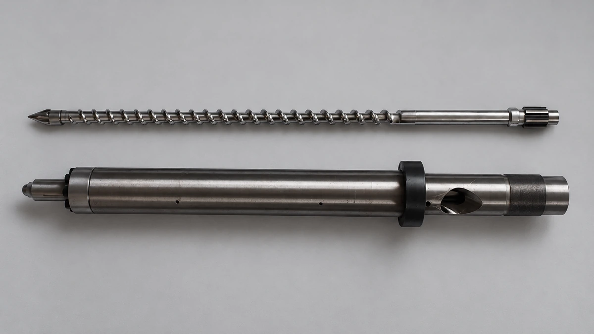
Your Injection Molding Shot Size Calculation Is Missing Melt Density
Nov 4, 2026
Learn the complete injection molding shot size calculation with melt density corrections, barrel utilization rules, runner system impact, and two worked examples.
Read ArticleLooking for something else?
Search by material, symptom or product and jump straight to the relevant page.
These are navigation suggestions based on keyword matching — not a quotation, not a delivery commitment, and not a substitute for engineering review. Final specification is confirmed by our engineers against your drawings and processed material.
Need help with screw barrel selection?
Share your machine model, processed material and application. Our team can help with pricing and technical support.