

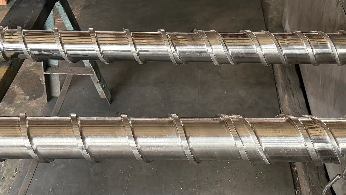
Understanding the Barrier Screw and Why It Exists
Imagine pulling a finished part off the line and spotting a white speck buried in the surface, an unmelt that sailed right through your process. You tweak temperatures, bump up back pressure, maybe slow down the screw speed, and the speck disappears for a shift or two before returning. The root cause often isn't your process settings at all. It's the screw geometry itself, specifically the way a conventional single-flighted design handles the transition from solid pellets to homogeneous melt.
That frustration is exactly what drove the development of the barrier screw more than half a century ago, and it remains one of the most effective upgrades a processor can make to improve melt quality, consistency, and throughput.
What Is a Barrier Screw
A barrier screw is a plasticating screw that incorporates a secondary flight, known as the barrier flight, into the transition (compression) zone. This additional flight physically separates the solid polymer bed from the developing melt pool by creating two distinct channels: one that retains unmelted solids and another that collects molten resin. The barrier flight clearance allows melt to pass over into the melt channel while preventing solid pellets from crossing, resulting in significantly improved melting efficiency and melt-temperature homogeneity compared to conventional single-flighted designs.
In practical terms, the barrier flight acts like a filter built directly into the screw geometry. As SpiraMelt Technologies explains, the primary channel continuously decreases in cross-sectional area as solids melt, while the auxiliary melt channel grows to accommodate increasing volumes of molten polymer. This controlled separation keeps fresh solid material pressed against the hot barrel surface, maximizing heat transfer where it matters most.
Why Barrier Screws Matter for Modern Processing
So why should you care about flight geometry when you've got heater bands and process controllers doing the heavy lifting? Because the real bottleneck in plasticating performance usually isn't heat input; it's how efficiently that heat reaches unmelted polymer.
In a conventional screw, a growing melt pool gradually occupies more and more of the channel width inside the transition section. That melt pool acts as an insulating blanket, reducing the barrel-surface area available for melting fresh solids. Eventually, the shrinking solid bed loses structural integrity and fragments, scattering cold, unmelted pieces into the melt pool. This phenomenon, known as solid-bed breakup, is a primary source of unmelts, pressure instability, and inconsistent melt temperature in both extrusion and injection molding.
A barrier screw attacks each of these pain points at the source:
- Unmelts and gels: By draining melt away from the solids channel, the design prevents solid-bed breakup and keeps pellet fragments from reaching downstream zones.
- Poor melt-temperature homogeneity: Continuous melt separation maintains high heat-transfer rates along the full length of the barrier section, producing a more thermally uniform output.
- Throughput limitations: With more barrel-surface area actively contributing to melting, processors can often increase screw speed, and therefore output, without sacrificing part quality.
- Pressure fluctuations: A stable solid bed means steadier pressure development, which translates to more consistent die flow or shot-weight repeatability.
These advantages explain why virtually every barrier screw extruder factory producing high-volume film, sheet, or pipe lines now offers barrier-geometry options as standard or preferred configurations. The technology has proven itself across polyolefins, nylons, and a wide range of other commodity and engineering resins.
This article walks through the complete picture: how the barrier flight works inside the barrel, the geometric parameters that govern performance, the major design variants and how they compare, polymer-specific selection guidance, real-world application differences between extrusion and injection molding, honest limitations, and a practical framework for choosing the right design. Whether you're troubleshooting persistent unmelts or evaluating a screw upgrade, the goal is to give you the engineering context behind the decision, not just a sales pitch.
The logical starting point is understanding exactly what happens to polymer inside that barrel channel, and why a second flight changes everything about the melting process.
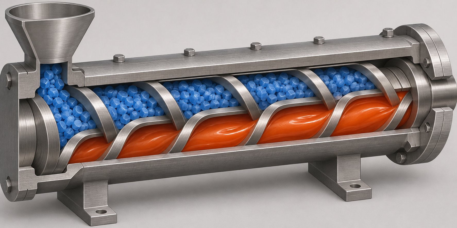
How a Barrier Screw Works Inside the Barrel
To appreciate what a barrier screw design actually accomplishes, you first need a clear picture of what happens inside a conventional single-flighted channel. The difference between the two isn't subtle; it fundamentally changes how polymer transitions from solid pellet to flowing melt.
Melting in a Conventional Screw vs a Barrier Screw
Picture a cross-section of a conventional screw channel somewhere in the transition zone. A thin film of molten polymer forms where the compacted solid bed contacts the hot barrel wall. As the screw rotates, the advancing main flight scrapes this melt film off the barrel surface and pushes it into a growing melt pool on one side of the channel. This mechanism was first described theoretically by Tadmor in 1966 and confirmed through Maddock's famous "screw-pull" experiments, where colored pellets revealed the solid bed shrinking in width while the melt pool expanded beside it.
Here's the problem: as that melt pool grows, it occupies an ever-larger share of the channel. The molten resin sitting between the solid bed and the barrel acts like an insulating layer, reducing the surface area where fresh solid polymer can contact the hot barrel. Melting slows down exactly when you need it to speed up. Worse, the narrowing solid bed eventually loses structural integrity, fragments under internal channel pressure, and disperses cold, unmelted chunks into the surrounding melt pool. This solid-bed breakup is unpredictable, and it's the single biggest source of unmelts and pressure surges in conventional processing.
A barrier screw extruder solves this by introducing a secondary flight, the barrier flight, that continuously drains melt away from the solid bed before it can accumulate and insulate. Molten polymer flows over the undercut barrier flight into a separate melt channel, while unmelted solids remain physically confined in the primary channel. The result? Fresh solid material stays in direct contact with the barrel wall along the entire length of the barrier section, maintaining high conductive and dissipative heat-transfer rates from start to finish.
| Performance Factor | Conventional Screw | Barrier Screw |
|---|---|---|
| Melt-film behavior | Melt film scraped into a growing melt pool that shares the channel with the solid bed, progressively insulating solids from the barrel | Melt film continuously drained over the barrier flight into a separate channel, keeping the barrel surface exposed to fresh solids |
| Solid-bed stability | Solid bed narrows until it fragments unpredictably (solid-bed breakup), scattering unmelted particles into the melt | Solid bed remains compact and structurally intact as the primary channel gradually narrows in a controlled fashion |
| Melt-temperature uniformity | Wide temperature variation; melt pool near the barrel runs hotter while solid fragments introduce cold spots | Narrower temperature distribution; melt is collected at a more consistent thermal state throughout the barrier section |
| Risk of unmelts | High, especially at elevated screw speeds where solid-bed breakup becomes more frequent | Significantly reduced; solids cannot cross the barrier flight into the melt channel without first melting |
The practical takeaway is straightforward: by physically segregating melt from solids, the barrier flight preserves the very conditions that make melting efficient. Research at Paderborn University has shown that solid-bed breakup in conventional screws becomes more frequent and severe at higher screw speeds, occurring predominantly near the end of the compression zone. A barrier screw injection molding or extrusion setup sidesteps this failure mode entirely, which is why processors often find they can push throughput higher without the melt-quality penalties they'd see on a general-purpose screw.
The Role of Barrier Flight Clearance
The gap between the top of the barrier flight and the inner barrel wall is arguably the single most critical dimension in the entire barrier screw design. This clearance is what controls the separation: it must be large enough for molten polymer to flow freely into the melt channel, yet small enough to prevent unmelted pellets or solid fragments from sneaking through.
Think of it as a precision gate. Set it too tight, and you create excessive shear heating in the melt film as it's forced through a narrow restriction. That extra shear raises melt temperature beyond what the process needs, increases the pressure drop across the barrier flight, and can even cause localized degradation of heat-sensitive resins. Set it too loose, and unmelted solids leak into the melt channel, defeating the entire purpose of the design and reintroducing the unmelt problems you were trying to eliminate.
The optimal clearance depends on several interacting variables:
- Screw diameter: Larger-diameter screws generally allow proportionally larger clearances because pellet sizes and solid-bed dimensions scale accordingly.
- Material rheology: Low-viscosity melts flow more readily through tighter gaps, while high-viscosity resins may need slightly more clearance to avoid excessive pressure buildup.
- Pellet geometry: Standard pellets, micropellets, and powder each present different risks for solids leakage at a given clearance setting.
- Barrel condition: A worn barrel effectively increases the clearance, which can degrade separation performance over time, even if the screw itself hasn't worn significantly.
Specific clearance values are proprietary to each screw manufacturer and vary with screw diameter, intended polymer family, and target throughput. If you're evaluating a barrier screw extruder for sale, always confirm the barrier flight clearance specification and understand how it was optimized for your target material. This is not a dimension you want to guess at; it should be confirmed with the screw or barrel manufacturer based on your exact processing conditions.
The interplay between barrier clearance and channel geometry raises a broader question: what are all the geometric parameters that collectively define how a barrier screw performs, and how do they interact? That's where the engineering gets genuinely interesting, and where small dimensional choices produce outsized effects on melt quality.
Key Geometric Parameters That Define Barrier Screw Performance
Barrier flight clearance matters enormously, but it's just one piece of a much larger geometric puzzle. Every dimension on a barrier screw, from the helix angle of each flight to the channel depth at the very last turn, influences how effectively solids separate from melt, how much pressure the screw generates, and ultimately whether your extrudate or molded part comes out clean or riddled with defects. What makes barrier screw design genuinely complex is that these parameters don't operate in isolation; they interact, sometimes in counterintuitive ways.
The following breakdown covers every critical geometric variable in one place, something most technical resources scatter across multiple articles or skip entirely. If you're specifying a new screw, troubleshooting a barrier screw temperature profile issue, or simply trying to understand why one design outperforms another, these are the dimensions that drive the difference.
Flight Geometry and Lead Angles
Imagine unwinding the screw flights into flat, straight channels laid out on a table. You'd see two helical paths: the main flight and the barrier flight, each wrapped around the screw root at a slightly different angle. That difference in helix angle, or lead angle, is the engine behind the entire solid-melt separation mechanism.
The main flight typically maintains a conventional helix angle, often close to a square-pitch configuration where the lead roughly equals the screw diameter. The barrier flight, however, is introduced at a steeper or shallower angle, depending on the specific design variant. Because the two flights have different pitches, they converge along the length of the screw, steadily changing the width ratio between the solids channel and the melt channel.
Here's the practical effect: as polymer advances down the screw, the solids channel progressively narrows while the melt channel widens. This geometric divergence mirrors what's physically happening to the material. The solid bed is shrinking as it melts, and the melt volume is growing. A well-designed barrier screw matches these channel-width changes to the expected melting rate of the target polymer so that the solid bed always fills its channel snugly without excessive compression or premature looseness.
When that match is off, problems follow quickly. If the solids channel narrows faster than the polymer actually melts, you build extreme localized pressure in the solids channel. Jim Frankland's analysis of an 8-inch barrier screw documented forces approaching 350,000 pounds generated by a solid plug trapped at the end of an overly aggressive solids channel, enough to bend the screw shaft 0.100 inches and cause catastrophic flight wear. Conversely, if the solids channel narrows too slowly, melt accumulates around the remaining solids, undermining the bed's structural integrity and recreating the very solid-bed breakup the design was meant to prevent.
The divergence angle between the two flights, therefore, is not arbitrary. It must be tuned to the melting characteristics of the specific polymer family being processed. This relationship between lead angle and melting rate is one of the primary reasons a barrier screw optimized for HDPE won't necessarily perform well on polystyrene, even at the same screw diameter.
Channel Depths and Compression Ratios
Channel depth is the other major lever controlling what happens inside the first plug of solid material as it travels through the screw channel and encounters the barrier section. The depth profile across feed, barrier, and metering zones determines the compression ratio, which directly governs pressure generation, solid-bed compaction, and ultimately melt quality.
In a barrier screw, the depth story is more nuanced than in a conventional design because you're managing two parallel channels simultaneously. The solids channel typically starts at a depth comparable to the feed-section depth and decreases as material advances, compressing the solid bed and maintaining intimate contact with the barrel wall. Meanwhile, the melt channel may start relatively shallow and deepen as it fills with increasing volumes of molten polymer.
Research comparing barrier and general-purpose screws on a 38 mm extruder at UMass provides concrete geometry data that illustrates this progression. In the studied barrier screw, the combined channel depth decreased from 7.57 mm in the feed section to as little as 0.50 mm at the end of the solids channel by turn 17, while the flight width (incorporating the barrier flight) expanded from 3.81 mm to 19.5 mm over the same span. That extreme depth reduction in the solids channel is what forces thorough melting before material exits the barrier section.
For quick reference, here are the key geometric parameters that collectively define barrier screw performance:
- Barrier flight clearance: The radial gap between the barrier flight tip and the barrel bore. Controls whether melt passes cleanly while solids are retained. Typical values are significantly larger than the main flight clearance but vary with screw diameter and target resin.
- Main flight lead angle: The helix angle of the primary (full-wiping) flight. Sets the base conveying pitch and channel width for the screw.
- Barrier flight lead angle: The helix angle of the secondary (undercut) flight. Its divergence from the main flight lead angle determines how rapidly the solids channel narrows and the melt channel widens.
- Solids-channel width progression: The rate at which the solids channel narrows along the barrier section. Must match the expected melting rate for the target polymer to avoid either wedging or bed breakup.
- Melt-channel width progression: The rate at which the melt channel widens, accommodating the growing volume of molten resin separated from the solid bed.
- Feed-section channel depth: Governs the initial volumetric intake. Typically 15-20% of the screw diameter for standard pellet feedstocks, though the exact value depends on feedstock bulk density and resin type.
- Solids-channel depth profile: The decreasing depth within the barrier section that compresses the solid bed. This depth interacts with channel width to define the true compression experienced by the polymer.
- Melt-channel depth profile: May remain constant or increase slightly to accommodate growing melt volume without excessive pressure drop.
- Metering-section channel depth: Sets the final pumping geometry downstream of the barrier section. The ratio of feed depth to metering depth defines the overall compression ratio.
- Overall L/D ratio: The total screw length divided by its diameter. Barrier screws generally require L/D ratios of 24:1 or greater to provide sufficient length for the feed, barrier, and metering sections. The UMass study used a 27:1 L/D, which is representative of many commercial barrier designs.
Compression ratio deserves special emphasis because getting it wrong creates cascading problems. A ratio that's too low, meaning the feed channel isn't deep enough relative to the metering channel, fails to compact the solid bed adequately. Entrained air can't escape forward through the melt, so it works backward through the hopper or, worse, gets carried into the part as voids or splay. A ratio that's too high overfeeds the downstream sections, generating excessive pressure that can plug mixing elements or overwhelm the barrier flight's ability to separate solids from melt. For PS resins, an optimal ratio near 3.0 is common, while ABS typically performs best around 2.5. Polyolefins such as LLDPE favor roughly 2.8.
These numbers shift further when a barrier section is involved because the barrier flight itself contributes additional compression beyond what the simple feed-to-metering depth ratio implies. This is why specifying a barrier screw purely by compression ratio, the way you might spec a general-purpose screw, is insufficient. The full depth and width profile across every turn of the barrier section matters.
With the geometric fundamentals established, a natural question emerges: how have different screw designers combined these parameters into distinct barrier configurations, and what trade-offs does each variant prioritize? The answer reveals a surprisingly diverse family of designs, each tailored to different processing challenges.
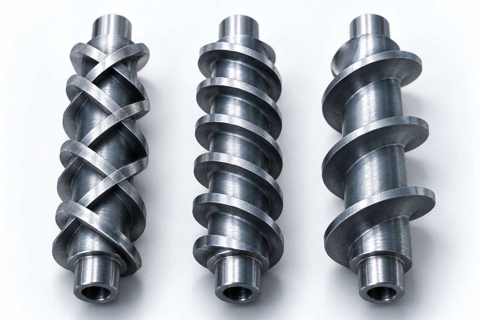
Major Barrier Screw Design Variants Compared
Not all barrier screws are built the same, and that distinction matters far more than most processors realize. The secondary flight concept may sound like a single idea, but over the decades it has evolved into a family of distinctly different geometries, each prioritizing different trade-offs between melting capacity, output volume, solid-bed handling, and pressure generation. Choosing the wrong variant for your resin and process is a fast path to the same melt-quality headaches you were trying to escape.
What follows is something rarely found in one place: a consolidated, side-by-side breakdown of every major barrier screw extrusion design, from the original patent concepts to the more specialized variants that emerged later. If you've ever wondered why two screws both labeled "barrier" perform nothing alike on the same polymer, the geometry differences explained below are the answer.
Maillefer, Barr, and Energy Transfer Designs
The Maillefer design, also called the crossing barrier, was one of the earliest barrier screw concepts to reach commercial use. Its defining geometric feature is a barrier flight that crosses from one side of the main channel to the other along the length of the barrier section. Imagine the solids channel starting at full width and the melt channel starting at zero width; as material advances, the barrier flight gradually trades that space, shrinking the solids channel to nothing while the melt channel expands to fill the entire cross-section. The solids channel effectively "crosses" the screw diameter from one flight flank to the opposite one.
A practical advantage of this crossing geometry is that there's no abrupt channel restriction at the point where the barrier flight begins. The solids channel width stays relatively constant at the start, which Jim Frankland notes can be beneficial for hard and slippery polymers whose fragile solid beds don't easily reshape to accommodate sudden cross-sectional changes. However, the crossing design has a significant limitation: because the solid bed must continuously deform as the channel crosses, the pressure required for that distortion can propagate back into the feed section, reducing feed efficiency and output. The barrel surface area exposed to the solid bed in the solids channel is also substantially less, roughly half, compared to a parallel barrier of the same axial length.
The Barr design, named after noted screw designer Robert Barr, introduced the parallel barrier concept. Here, the barrier flight runs roughly parallel to the main flight rather than crossing it. Both the solids channel and the melt channel exist side by side along the length of the barrier section, with the solids channel narrowing and the melt channel widening as the lead angles diverge. This parallel arrangement provides considerably more melting area. On a 3.5-inch screw with standard pitch and 10 diameters of barrier flight, the parallel configuration typically delivers approximately one-third more area in the solids channel than a crossing design of equivalent length. Since melting capacity is largely proportional to the surface area where solid polymer contacts the barrel, this translates directly into higher throughput potential with quality melt.
The trade-off? The parallel barrier does introduce a geometry change at the start of the barrier section where the melt channel must begin. For polymers with fragile solid beds, this transition can disrupt solid-bed formation if not carefully managed. Good parallel designs compensate with features like a gradual barrier introduction, a small opening into the melt channel to accommodate early melting, or a brief decompression zone to offset the sudden loss of channel cross-section.
The Dray and Lawrence design, sometimes called the energy-transfer type, builds on the parallel barrier concept by increasing the helix angle of the main flight within the barrier section beyond standard pitch. On a 3.5-inch screw, for example, the lead might increase by 25% to 4.375 inches, producing a helix angle of roughly 21.7 degrees. The wider channels that result make it easier to introduce the barrier and melt channel without pinching the solids channel width, essentially combining the parallel barrier's melting advantage with less disruption of the solid bed.
You might expect that wider channels would dramatically boost melting area, but the math tells a more nuanced story. As Frankland has explained, the increased helix angle yields fewer turns of barrier flight over the same axial length, roughly 8 turns versus 10 on that 3.5-inch screw. The net melting-area gain is less than 10%, and even that modest advantage is partially offset by reduced viscous dissipation per unit length at the longer helix angle. The real benefit of the Dray/Lawrence approach is the ability to pack more volume into the barrier section for higher output, rather than a proportional increase in melting efficiency. For that reason, it has become particularly popular in high-output barrier screw extrusion applications such as blown film and sheet lines where throughput is the primary driver.
MC-3, Kim, and Other Variants
Beyond the three foundational designs, several more specialized variants have emerged to address specific processing challenges.
The MC-3 (or double-wave) concept takes a fundamentally different approach to melt-solid management. Instead of a classic narrowing solids channel and widening melt channel, the MC-3 uses two or three parallel channels of equal width separated by a barrier flight low enough for melt to flow over. The distinguishing feature is that channel depths undulate in a wave-like pattern, with one channel running shallow while the adjacent channel runs deep, then reversing half a turn later. Allan Griff describes how melt flows from the shallow channel to the deep one, and then back again as depths reverse, forcing the material through repeated cross-channel mixing events as it moves downstream. The result is excellent distributive mixing and flow stabilization, though at the cost of a less aggressive solids-separation mechanism than a true barrier design. The MC-3 excels where mixing quality and output stability are higher priorities than raw melting capacity.
The Kim screw employs a unique approach to channel geometry within the barrier section. Rather than relying solely on diverging lead angles to control channel widths, the Kim design manipulates the depth profile of the melt channel more aggressively, often incorporating a secondary mixing element integrated directly into the barrier zone. The intent is to achieve more thorough melt homogenization before material even reaches the metering section, which can reduce or eliminate the need for separate downstream mixing devices. This makes it attractive for applications requiring tight melt-temperature tolerances, though the more complex geometry can complicate cleaning during material changeovers.
It's also worth noting hybrid configurations that blend elements from multiple design families. A parallel barrier section with standard (non-increased) helix angle, for instance, falls somewhere between the Barr and Dray/Lawrence concepts. These hybrids sacrifice some melting-area advantage but produce narrower channels that can deliver lower melt temperatures, making them well suited to softer polymers and resins with low energy requirements. Some designs, including one originally patented by DuPont, even start the barrier by retarding the main flight pitch to form the barrier channel backward, specifically to minimize disruption of the solid bed at the transition point.
When you're evaluating options from any barrier screw extruder manufacturer, the design variant is arguably more important than the brand name on the quote. The table below consolidates the critical distinctions:
| Design Name | Key Geometry Feature | Primary Advantage | Known Limitation | Best-Fit Application |
|---|---|---|---|---|
| Maillefer (Crossing) | Barrier flight crosses from one channel side to the other; solids channel starts at full width, ends at zero | No abrupt channel restriction at barrier start; handles hard/slippery polymers with fragile solid beds | Lower melting area vs. parallel types; continuous solid-bed distortion can reduce feed efficiency and output | Lower-energy-requirement polymers (low melting point, low specific heat); torque-limited extruders with sufficient L/D |
| Barr (Parallel) | Barrier flight runs parallel to main flight; diverging lead angles create narrowing solids channel and widening melt channel | ~33% more solids-channel area than crossing design at same length; higher melting capacity per unit length | Geometry change at barrier start can disrupt fragile solid beds if not carefully designed | Higher-energy-requirement polymers (HDPE, nylon, PP); processes demanding maximum melt quality at moderate to high output |
| Dray/Lawrence (Energy Transfer) | Parallel barrier with increased helix angle (wider channels) in barrier section | More channel volume for higher output; reduced solid-bed disruption at barrier introduction | Fewer barrier flight turns at same axial length; melting-area gain under 10%; often needs metering section for head-pressure generation | High-output extrusion (blown film, sheet, pipe); applications where throughput takes priority over minimum screw length |
| MC-3 (Double-Wave) | Equal-width parallel channels with oscillating (wave) depth profiles, out of phase | Excellent distributive mixing and flow stabilization; melt moves back and forth across barrier for thorough blending | Less aggressive solids-separation than classic barrier designs; may not fully prevent unmelts without downstream mixing | Applications prioritizing mixing quality and output stability over raw melting rate; color-change-sensitive processes |
| Kim | Aggressive melt-channel depth manipulation with integrated mixing element within the barrier zone | High melt homogeneity before metering section; may reduce or eliminate need for separate downstream mixers | Complex geometry complicates cleaning during material changeovers; design less widely standardized | Tight melt-temperature-tolerance applications; engineering resins where homogeneity is paramount |
One additional factor that applies across all variants: the exit end of the solids channel can be either closed or open. A closed end requires that melting is substantially complete before material reaches the channel terminus, or the plugged solids will cause pressure fluctuations, accelerated screw wear, and poor thermal homogeneity. An open end lets residual solids pass into the metering section, but demands that a downstream mixing element, such as a Maddock section, finishes the job. Getting this detail right requires careful melting-rate calculations matched to the specific polymer, which is why any reputable barrier screw extruder manufacturer will ask detailed questions about your resin, throughput target, and barrel geometry before recommending a design.
Knowing which variant exists is only half the equation. The other half is understanding which polymers play nicely with barrier geometry in the first place, and which ones introduce risks that no flight configuration can fully mitigate.
Which Polymers Benefit Most from Barrier Screws
A barrier screw's performance isn't determined by geometry alone. The polymer running through it has just as much influence on the outcome. Semi-crystalline resins, amorphous resins, and heat-sensitive materials each melt through fundamentally different mechanisms, and those differences dictate whether a barrier design helps, hurts, or simply doesn't matter much. Yet polymer-specific guidance is one of the biggest gaps in most barrier screw discussions. Let's fill it.
Semi-Crystalline Polymers and Barrier Screw Selection
Semi-crystalline resins like HDPE, LDPE, LLDPE, PP, and nylon are, as a group, the strongest candidates for barrier designs. The reason comes down to how they melt. As John Bozzelli explains, semi-crystalline polymers behave much like ice: they remain hard and rigid until they reach their melting point, then require an additional dose of energy to overcome the heat of fusion and break up their ordered crystalline structure. There's no gradual softening along the way. A nylon 6 pellet sitting at one degree below its melting point is essentially just as rigid as it was at room temperature.
This sharp melting behavior creates two related challenges inside the barrel. First, the total energy demand is significantly higher. Nylon 6, for example, requires roughly twice the energy per kilogram as ABS, about 716 BTU/kg versus 342, despite processing at similar temperatures. Second, because the pellets stay hard right up until the melting threshold, solid-bed breakup is violent and unpredictable. Hard fragments scatter into the melt pool and resist further melting because they've lost barrel-wall contact. These cold, rigid chunks are the classic unmelts that end up embedded in finished parts or gouging screw flights.
Barrier designs directly counter both problems. By continuously draining melt away from the solid bed, they keep fresh crystalline solids pressed firmly against the hot barrel surface, maximizing the heat-transfer rate exactly where it's needed most. The solid bed retains structural integrity because the narrowing solids channel provides controlled compression rather than allowing the bed to fragment on its own. For polyolefins and nylons, parallel barrier variants like the Barr design tend to perform best because they offer the greatest melting area per unit length, matching the high energy demand of these resins. High-output polyolefin applications, such as blown film lines running LLDPE, often pair an energy-transfer (Dray/Lawrence) variant with a downstream mixing section for throughput-driven production.
The barrier screw temperature profile also shifts meaningfully for semi-crystalline materials. Because melting doesn't begin until the crystalline melting point is reached, the feed zone should remain cool enough to maintain solid conveying friction without premature softening. Barrel temperatures in the barrier zone then ramp aggressively to drive the solid bed past that melting threshold as quickly as possible. Even small machines running a 20 mm diameter barrier screw for laboratory or pilot-scale work follow this principle: keep the feed cold, push energy hard in the barrier section, and let the metering zone stabilize the melt.
Amorphous and Heat-Sensitive Resins
Amorphous polymers, including PS, ABS, PC, and PMMA, present a completely different melting picture. As Bozzelli puts it, amorphous resins melt like frozen butter. They begin softening well below their processing temperature and continue to soften progressively as energy increases. There's no crystalline structure to overcome, no sudden heat-of-fusion barrier, and substantially less total energy required per kilogram.
This gradual softening makes amorphous resins far more forgiving inside any screw design. A partially melted amorphous pellet behaves like taffy: if it gets wedged between a flight and the barrel wall, it deforms rather than gouging metal. Solid-bed breakup, when it occurs, is less damaging because the fragments are already semi-molten. A general-purpose screw may produce acceptable results on amorphous resins in many situations, which means the incremental benefit of a barrier design is smaller than it is for semi-crystalline materials. Barrier screws still improve melt homogeneity and can enable higher throughput on amorphous polymers, but they're a conditional rather than essential upgrade.
Heat-sensitive resins introduce a different category of risk entirely. PVC is the prime example: it doesn't melt to a low-viscosity flow like polyolefins but instead transitions into a gelled, elastic-plastic state. Exposure to excessive temperature or prolonged residence time triggers degradation, releasing hydrochloric acid and producing discoloration, black specks, or brittleness. The barrier section's additional shear at the flight clearance and the potential for material hang-up in narrow channel transitions make standard barrier designs risky for rigid PVC. Most rigid PVC processing relies on twin-screw extruders with low-shear geometry and moderate compression ratios (typically 1.3 to 1.6) rather than single-screw barrier configurations. Certain engineering resins with narrow processing windows, such as some grades of POM and thermally sensitive PET, face similar concerns where the added residence time in the barrier section can push material past its degradation threshold.
The following categorization provides a practical starting point for evaluating whether a barrier design fits your resin:
- Strong candidates for barrier screws: HDPE, LDPE, LLDPE, PP, nylon 6, nylon 66. These semi-crystalline resins benefit most from improved solid-bed stability and the higher melting efficiency that barrier geometry provides.
- Conditional candidates: PS, ABS, PC, PMMA, PETG. Amorphous resins gain melt-homogeneity and throughput improvements, but a well-designed general-purpose or modified conventional screw may deliver acceptable results, especially at moderate output rates or smaller shot sizes.
- Poor candidates (or requiring specialized design): Rigid PVC, certain POM grades, thermally sensitive PET, and heavily filled compounds prone to hang-up. For these materials, the added shear, residence time, and cleaning difficulty of a barrier section often outweigh the melting benefits. Modified conventional screws with optimized compression profiles, or twin-screw configurations, are typically preferable.
Polymer selection is the starting point, but the application itself, whether extrusion or injection molding, changes how a barrier screw's advantages translate into real-world performance gains. The same resin can demand very different things from the same screw geometry depending on whether it's feeding a flat die or reciprocating inside a barrel.
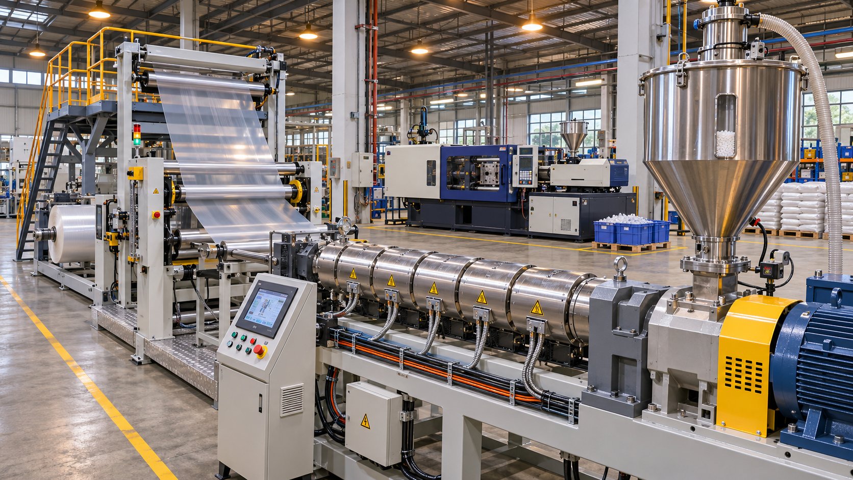
Barrier Screw Applications in Extrusion and Injection Molding
A blown film line running LLDPE at 800 pounds per hour and a 1000-ton injection molding machine cycling thin-wall HDPE containers share at least one thing in common: both benefit from better melting, and both can see measurable process improvements from a barrier screw. But the way those improvements show up on the shop floor, and the design details that matter most, differ considerably between the two processes. Most barrier screw discussions focus almost exclusively on extrusion. That leaves injection molders to figure things out on their own, which is a missed opportunity given how much cycle time and shot consistency stand to gain.
Barrier Screws in Extrusion Applications
Extrusion is where barrier designs first proved their worth, and it remains the application space with the longest track record. Research published in the Journal of Plastic Film and Sheeting confirms that screws with barrier flighted melting sections are the preferred choice for melting and extruding polyethylene resins into films using both smooth-bore and grooved-bore single-screw extruders, delivering higher rates and lower discharge temperatures compared to general-purpose designs.
Here's how those advantages translate across specific extrusion processes:
- Blown film: This is arguably the single largest application for barrier screws. Blown film demands tight melt-temperature uniformity to maintain consistent bubble geometry and gauge control. Even small temperature variations cause thickness bands in the film. A barrier design's ability to deliver homogeneous melt at lower average discharge temperature directly improves bubble stability, reduces frost-line height variability, and enables higher line speeds without sacrificing optical clarity or mechanical properties. Energy-transfer (Dray/Lawrence) variants are especially popular on high-output blown film lines where throughput is the dominant priority.
- Cast film and sheet: Similar to blown film, cast processes are sensitive to melt-temperature uniformity because variations cause cross-web thickness inconsistency and surface defects. The reduced risk of unmelts is critical in thin-gauge cast films where even microscopic gels or unmelted particles create visible defects or pinhole failures.
- Pipe and profile: Pipe extrusion, particularly large-diameter HDPE pipe, benefits from the lower melt temperatures that barrier screws produce. Lower discharge temperatures mean less energy dumped into the cooling bath and shorter cooling line requirements. For profile extrusion, where complex die geometries demand uniform viscosity across the entire melt stream, the tighter thermal distribution from a barrier design translates into more consistent die swell and tighter dimensional tolerances.
- Blow molding: Continuous-extrusion blow molding shares many of the same requirements as pipe extrusion, with the added demand for consistent parison weight and wall-thickness distribution. Barrier screws help stabilize parison formation by reducing pressure fluctuations caused by unmelt surges and solid-bed breakup events.
Across all of these processes, the performance story is consistent: better melting efficiency means you can push output higher before melt quality degrades, and the resulting lower discharge temperatures reduce downstream cooling demands. That combination of more throughput and less cooling time is why barrier geometry has become the de facto standard on polyolefin extrusion lines rather than a specialty upgrade.
Barrier Screws in Injection Molding
Injection molding introduces a wrinkle that extrusion doesn't have: the screw must function both as a plasticator and as a plunger. During recovery, the screw rotates to melt and convey resin forward, building a shot of molten polymer ahead of the screw tip. During injection, rotation stops and the entire screw drives forward like a piston, pushing that shot through the nozzle, runner, and into the mold cavity. This dual role changes how barrier screw benefits manifest in practice.
The most immediate gain is reduced screw recovery time. Recovery, the time it takes the screw to rotate back to its set position after injection, is the phase most directly limited by melting efficiency. A general-purpose screw melting recycled HDPE, for example, might require a recovery time that exceeds the cooling time, forcing the overall cycle to stretch beyond what the part actually needs. A case study documented by Nordson illustrates this clearly: switching from a general-purpose screw to a barrier design on a 1000-ton machine processing 100% recycled HDPE dropped recovery time enough to reduce cooling time and cut the overall cycle by 12%, boosting daily output from 1,041 to 1,184 parts.
Why does faster recovery matter so much? Because in a robust molding process, recovery time should finish one to two seconds before the set cooling time expires. If recovery runs long, the machine sits waiting for the screw to finish plasticating before it can open the mold, and every second of unnecessary cycle time multiplies across thousands of shots per day. By melting resin more efficiently, a barrier design completes recovery faster and frees up that time margin.
Beyond recovery speed, injection molders see improvements in several other areas:
- Shot-weight repeatability: A thermally uniform melt has consistent density, which translates directly into more repeatable shot weights. Processors running tight-tolerance parts, particularly in packaging, medical devices, and automotive components, often find that switching to a barrier design tightens their Cpk values without any other process changes.
- Lower melt temperature at equivalent output: Because the barrier section melts more efficiently, less viscous dissipation and less back pressure are needed to achieve complete melting. The result is a lower average melt temperature, which shortens cooling time and further reduces cycle.
- Reduced back-pressure requirements: General-purpose screws often need elevated back pressure to force remaining solids through the metering section and improve mixing. Barrier designs accomplish melting in the barrier section itself, allowing processors to run lower back pressures without sacrificing melt quality. Lower back pressure reduces wear, lowers melt temperature, and decreases the risk of drool at the nozzle.
One consideration unique to injection molding is compatibility with the non-return valve (check ring) at the screw tip. The barrier section must deliver melt that's clean enough, free of unmelted solids and pressure spikes, to allow the check ring to seat consistently. Solid fragments passing through a worn or improperly designed barrier section can lodge under the check ring seat, causing it to leak during injection and degrading shot-weight control. This means barrier flight clearance is even more consequential in injection molding than in extrusion, where there's no check valve to contaminate.
Integration with Mixing Sections and Metering Zones
Whether in extrusion or injection molding, the barrier section is just one component of a complete screw design. It doesn't operate in isolation; its output feeds directly into downstream elements that finish the job of homogenization, pressure generation, and melt conditioning. Understanding that sequence matters because a poorly matched downstream section can undo the advantages the barrier section provides.
A typical barrier screw follows this zone progression from feed hopper to discharge:
- Feed section: Deep-channel zone that accepts solid pellets from the hopper and conveys them forward through frictional drag against the barrel wall. Channel depth and flight geometry here are optimized for the bulk density and friction characteristics of the target feedstock.
- Barrier (transition) section: The dual-channel zone where the barrier flight separates solids from melt. Solids channel narrows progressively; melt channel widens. This is where the majority of melting occurs.
- Mixing section (optional but common): A distributive or dispersive mixing element positioned immediately after the barrier section. Industry expert Jim Frankland emphasizes that distributive mixers are usually the better choice after a barrier section, since the material should already be fully melted. Adding a dispersive (high-shear) mixer at this point often just raises melt temperature and increases pressure drop without meaningful benefit. Distributive types like Saxton, pin, or pineapple mixers homogenize temperature and blend color or additives with minimal added shear.
- Metering section: A constant-depth channel downstream of the mixing section that generates the pumping pressure needed to push melt through the die or accumulate a shot ahead of the screw tip. Channel depth here, relative to the feed section, defines the overall compression ratio and controls discharge pressure stability.
- Screw tip or non-return valve (injection molding only): In injection molding, the screw terminates in a check-ring assembly that allows melt to flow forward during recovery but seals during injection to prevent backflow. The metering section must deliver consistent, solids-free melt to this valve for reliable seating and repeatable shot control.
The choice between distributive and dispersive mixing deserves a closer look because it's a common source of mismatch. Dispersive mixers like the Maddock (also known as the UCC or Leroy design) were originally developed to compensate for the incomplete melting of conventional screws. They subject material to high shear as it passes through a narrow clearance gap, breaking up any remaining solids. On a properly functioning barrier screw, that job is already done. Adding a dispersive mixer after a barrier section, as Frankland points out, "would needlessly increase the melt temperature, reduce the output because of the added pressure drop, and result in greater energy requirements during both the extrusion and the subsequent cooling processes."
Distributive mixers, by contrast, work by dividing the melt stream into many layers and recombining them without imposing aggressive shear. A Saxton mixer divides melt into multiple channels with interrupted flights allowing cross-channel flow. Pin mixers create exponential divisions based on the number of pins and rows, breaking laminar-flow boundaries and blending components of different viscosities. Pineapple mixers converge divided streams at varying angles for chaotic mixing, which is particularly effective for color distribution. Each type carries trade-offs in pressure drop and mixing intensity, but all are better suited to the already-melted output of a barrier section than a high-shear alternative.
For processors asking whether a 3.5 extrusion screw should have barrier flights or a mixer, the answer is often both, but in the right order and the right type. The barrier section handles melting; a distributive mixer downstream handles homogenization. Stacking a dispersive mixer onto a barrier screw is one of the most common specification errors in the industry, and it costs processors in melt temperature, energy, and throughput every hour the line runs.
Getting the full screw assembly right, barrier section, mixer, and metering zone working together as a system, delivers the kind of results that make the investment worthwhile. But every system has limits, and barrier screws are no exception. Understanding where those limits lie, and recognizing the early signs of wear and performance degradation, is what separates processors who get lasting value from those who end up chasing new problems.
Limitations, Wear Indicators, and Troubleshooting
Every preceding section of this article has built a compelling case for barrier screws: better melting, tighter thermal uniformity, higher throughput, faster recovery. All true. But a balanced evaluation demands equal honesty about the downsides, and there are real ones. Processors who invest in barrier geometry without understanding its limitations, wear characteristics, and maintenance requirements often trade one set of headaches for another. This is the section most technical resources skip entirely, and it's arguably the one that saves you the most money in the long run.
Honest Limitations and When Not to Use a Barrier Screw
A barrier screw is not a universal solution. There are specific situations where the added complexity works against you rather than for you. Before committing to a barrier feed screw upgrade or specifying one on a new machine, consider the following caveats:
- Higher initial cost: The dual-flight geometry is more complex to machine than a standard single-flighted design. Expect to pay 30-50% more for a barrier screw than an equivalent general-purpose screw of the same diameter and metallurgy. That premium is justified when melt quality or throughput improvements generate a return, but it's wasted money on processes where a conventional screw already delivers acceptable results.
- Longer lead times: Because barrier screws require tighter tolerances on the secondary flight and more careful matching to barrel dimensions, custom and replacement orders typically take longer to manufacture than general-purpose screws. Plan accordingly during scheduled maintenance windows; a barrier feed screw manufacturer rarely stocks your exact configuration on the shelf.
- Reduced material-change flexibility: The dual-channel geometry with its narrow solids channel and controlled clearances creates more surface area where residual polymer can hang up during color or material changes. Purging a barrier design takes longer and consumes more purge compound than cleaning a simple single-flighted screw. If your production schedule involves frequent resin or color changeovers, the downtime penalty can offset the melting-efficiency gains.
- Potential for material hang-up and degradation: The transition point where the barrier flight begins and the corners of the narrowing solids channel are prime locations for polymer to stagnate, particularly with heat-sensitive resins. Stagnant material degrades over time, producing black specks, carbon contamination, or discolored streaks that are difficult to trace back to the screw without a pull-and-inspect procedure.
- More complex troubleshooting: When a general-purpose screw produces unmelts, the diagnostic path is relatively straightforward: check compression ratio, barrel temperatures, screw speed, and back pressure. When a barrier screw produces problems, the diagnostic space expands to include barrier flight clearance condition, solids-channel geometry match to the current resin, barrel bore wear affecting the clearance gap, and potential solid-bed wedging at the end of the barrier section. You're solving a more complex system, which demands a deeper understanding of the underlying mechanics.
- L/D requirements: Barrier designs generally require an L/D ratio of 24:1 or greater to accommodate the feed, barrier, and metering sections with adequate length in each zone. If your machine has a short barrel, say 20:1, there simply isn't enough length to fit a properly proportioned barrier section without compromising the feed or metering zone. Attempting to shoehorn a barrier into a short L/D often produces worse results than a well-designed conventional screw optimized for that length.
- Not ideal for filled or abrasive compounds: Glass-fiber-reinforced resins, mineral-filled compounds, and recycled streams with contaminants accelerate wear on the barrier flight far faster than on a standard flight. The barrier flight's undercut clearance is already tighter than the main flight clearance, so even modest abrasive wear degrades the separation function quickly. If you're processing highly filled materials, expect significantly shorter service life from the barrier section.
The bottom line? If your process runs frequent changeovers on a short-barreled machine processing heat-sensitive or heavily filled resins, a barrier screw may create more problems than it solves. Recognizing when not to use one is just as valuable as knowing when it's the right call.
Wear Patterns, Maintenance, and Replacement Timing
Every screw wears. That's an unavoidable reality of pushing abrasive polymer under pressure against a metal barrel for thousands of hours. What makes barrier screw wear uniquely consequential is where it matters most. On a general-purpose screw, flight-tip wear increases the clearance between the flight land and the barrel wall, reducing pumping efficiency and allowing more polymer to leak backward over the flights. Output drops gradually, and processors compensate by bumping screw RPM. It's a slow, predictable degradation curve.
On a barrier screw, the stakes are different. The barrier flight clearance is the precision gate controlling the entire solid-melt separation mechanism. When that flight wears, the clearance opens up, and unmelted solids begin leaking into the melt channel. You don't just lose pumping efficiency; you lose the fundamental function the design was built to perform. A worn barrier flight turns your barrier screw into an expensive, hard-to-clean general-purpose screw that's worse than a dedicated GP design because the residual geometry still creates hang-up points without delivering separation benefits.
Here's what to watch for:
Indirect indicators during operation are your first line of defense. Predictive maintenance data from extrusion lines reveals that several measurable parameters shift in characteristic ways as screw condition degrades:
- Output rate versus screw RPM: As wear progresses, it takes more RPM to achieve the same lb/hr output. Tracking this ratio over weeks and months reveals the wear curve specific to your screw, barrel, and material combination. A decline of 15% or more from baseline typically indicates the screw has moved past the marginal zone into replacement territory.
- Melt-temperature deviation: Worn screws generate more shear heat because polymer slips over degraded flights rather than being conveyed cleanly. If your melt temperature is running 8-15 degrees Fahrenheit above barrel setpoints and climbing, barrier flight wear is a likely contributor. Deviations exceeding 15 degrees Fahrenheit generally warrant a screw pull.
- Pressure fluctuations: This is the signature symptom of barrier flight failure. Rhythmic melt-pressure oscillations, often in the range of 100-500 PSI at regular intervals, indicate that solid fragments are periodically leaking past the worn barrier clearance and disrupting the melt stream. The surging shows up downstream as wall-thickness variation in extruded products or shot-weight scatter in injection molding.
- Motor amperage at constant RPM: Changes in motor load at the same screw speed indicate shifting melting behavior. An increase of more than 10% from baseline at rated RPM is a strong signal that wear has altered the screw's processing characteristics enough to require action.
- Specific energy (kWh/lb): This is the single most sensitive indicator of overall screw condition. As wear progresses, specific energy initially decreases (reduced pumping efficiency means less energy transferred per pound), then increases as operators compensate with higher RPM.
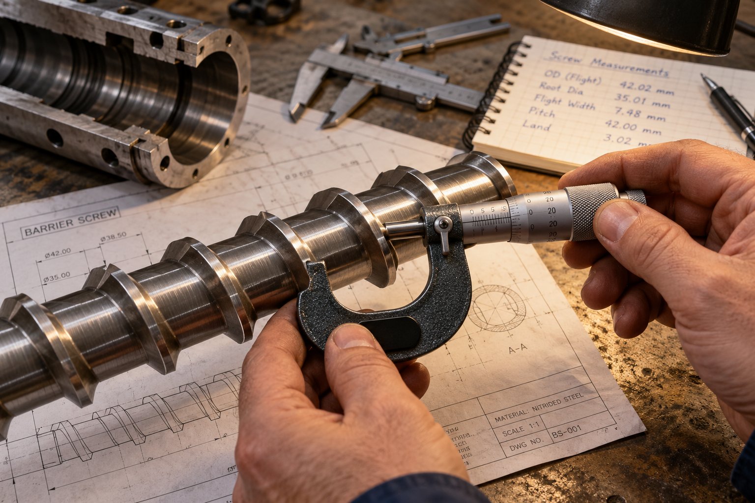
Direct measurement during scheduled shutdowns provides definitive confirmation. When you pull the screw, measure the barrier flight OD at multiple points along the barrier section. Industry data suggests that new screws typically run 0.002-0.004 inches of clearance per side with the barrel. At 0.006-0.010 inches, performance is marginal. Beyond 0.010 inches, the screw needs rebuilding or replacement. For barrier flights specifically, these thresholds should be considered even more conservatively because the barrier clearance was already larger than the main flight clearance by design. A barrier flight that has worn to the point where its clearance approaches or exceeds the main flight clearance has effectively ceased functioning as a barrier.
Also inspect the solids channel near its terminus, the narrowest point at the end of the barrier section. This is where the highest compressive forces act on remaining solids, and it's where you'll see the most aggressive wear. Galling, scoring, or visible metal loss in this region confirms that the solid bed was being over-compressed or that hard polymer fragments were being forced through a closing channel, a condition that generates enormous localized pressure and accelerates metal fatigue.
Barrel condition interacts directly with barrier screw performance. Even a perfectly maintained screw can't compensate for a worn barrel. As the barrel bore opens up from wear, the effective clearance at both the main flight and barrier flight increases simultaneously. Barrel bore ovality, where different sections wear unevenly into an egg-shaped cross-section, is particularly damaging because it creates variable clearance around the circumference. Material can leak past the barrier flight on the worn side while being properly retained on the tight side, producing intermittent unmelts that are maddeningly inconsistent and nearly impossible to diagnose without pulling the screw and measuring the barrel bore.
Grooved feed sections add another variable. The grooves dramatically increase solids-conveying pressure, which pushes material into the barrier section with more force than a smooth-bore barrel. If the grooves themselves wear down, the conveying pressure drops, and the carefully calibrated melting-rate assumptions built into the barrier geometry no longer hold. The result is either starved melting (if groove wear reduces conveying) or over-pressurized solid beds (if the barrier section was designed for smooth-bore feeding and someone installs it on a grooved machine).
Barrel temperature uniformity matters too. A failing heater band in the barrier zone creates a cold spot on the barrel wall, slowing local melting and allowing the solid bed to persist deeper into the barrier section than the geometry was designed to accommodate. Monitoring heater duty cycles by zone provides early warning: if a zone in the barrier region is trending toward 90% or higher duty, the heater band is approaching failure and will soon compromise the melting profile the screw depends on.
Refurbish versus replace? The decision depends on the type and extent of wear. Barrier flight resurfacing through PTA (plasma transferred arc) welding on the flight crests followed by precision grinding can restore a worn screw to original specifications, and the hard-faced overlay typically more than doubles the service life of a nitrided screw prior to refurbishment. However, if the screw root has worn significantly, if the channel geometry has distorted, or if the barrier flight has worn so far that re-welding can't restore the design clearance, replacement is the more reliable path. A reputable barrier feed screw manufacturer or refurbishment specialist should evaluate the screw dimensionally and provide an honest assessment before committing to either option.
Building a wear history for each screw, tracking the indirect indicators continuously and correlating them with direct measurements at each screw pull, transforms replacement timing from guesswork into a predictable maintenance event. After two or three replacement cycles with good data, you'll be able to forecast when the next change is needed within a few weeks, ordering the replacement screw in advance and scheduling the swap during a planned shutdown rather than scrambling after a catastrophic failure.
Knowing the limitations and wear realities of barrier screws doesn't diminish their value; it sharpens your ability to extract maximum performance from the investment. The next logical step is putting all of this knowledge into a structured selection framework: how do you match the right barrier design to your specific polymer, machine, and production requirements?
How to Select the Right Barrier Screw for Your Process
Understanding limitations and wear patterns is essential background, but at some point every processor faces the same practical question: which barrier screw design actually fits my machine, my resin, and my production targets? The answer is never a single model number pulled from a catalog. It's a systematic evaluation that starts with your specific process requirements and works outward through machine constraints, barrel condition, and downstream equipment. Skip a step and you risk spending thousands on a barrier flight screw that underperforms a well-matched general-purpose design.
The framework below distills the decision into a logical sequence. Work through it in order, because each step constrains the options available in the next.
Decision Criteria for Barrier Screw Selection
- Identify your target polymer and its melting behavior. Is it semi-crystalline with a sharp melting point (HDPE, PP, nylon) or amorphous with gradual softening (PS, ABS, PC)? Semi-crystalline resins generate the largest return on a barrier investment. Heat-sensitive resins like rigid PVC may rule out barrier geometry entirely. If you're running multiple resins on the same machine, weigh how frequently you change over; a barrier design's cleaning difficulty may outweigh its melting advantage in high-changeover environments.
- Define your throughput and melt-quality requirements. Are you chasing higher lb/hr output, tighter melt-temperature uniformity, fewer unmelts, or all three? Blown film and cast film lines typically prioritize thermal homogeneity and low discharge temperature, pointing toward parallel (Barr) or energy-transfer (Dray/Lawrence) variants. Barrier feed screws for injection molding prioritize fast recovery time and shot-weight repeatability, which often favor a parallel barrier with a distributive mixing section downstream.
- Document your existing machine platform. Measure and confirm screw diameter, L/D ratio, available drive torque, and maximum allowable screw RPM. A barrier screw generally requires an L/D of 24:1 or greater to accommodate properly proportioned feed, barrier, and metering zones. If your machine runs a 20:1 barrel, a full barrier section may not fit without unacceptable compromises. Drive torque is equally important: barrier designs generate higher channel pressures than general-purpose screws, especially during startup, and an undersized gearbox limits how aggressively you can run.
- Assess barrel condition. Pull the screw and measure the barrel bore at multiple points along its length. A worn barrel effectively increases barrier flight clearance regardless of the screw's condition, degrading the solid-melt separation you're paying for. If bore measurements show significant wear or ovality, replacing or relining the barrel before installing a new barrier screw is the only way to ensure the investment performs as designed. Ignoring barrel condition is one of the most expensive shortcuts in screw specification.
- Evaluate grooved-feed compatibility. If your extruder has a grooved feed section, the barrier screw design must account for the dramatically higher solids-conveying pressure that grooves produce. As Plastics Technology details, grooved-feed extruders can generate pressures up to 15,000-20,000 psi at the end of the groove section, far exceeding smooth-bore pressures of 3,000-4,000 psi. Barrier screws paired with grooved feeds need shallower feed-section channels, typically 0.25-0.4 inches deep on a 3.5-inch screw, compared to 0.6-0.7 inches for smooth-bore designs. The shallower channels maintain forward force in the grooves and prevent over-pressurizing the barrier section. Getting this match wrong risks catastrophic pressure buildup or, at minimum, starved melting and poor output efficiency. If you're considering adding barrier flights on a 3.5 Davis Standard extruder screw or a similar platform with grooved feeding, the screw geometry must be engineered specifically for that feed configuration.
- Choose between single-start and multi-start configurations. A single-start barrier screw has one main flight and one barrier flight, the most common arrangement for general-purpose and moderate-output applications. Multi-start designs use two or more main flights with corresponding barrier flights, effectively creating parallel processing channels that increase throughput capacity at the same screw RPM. Multi-start configurations suit large-diameter extruders (typically 4.5 inches and above) where the channel width on a single-start design would become so wide that the solid bed loses structural integrity. For smaller machines and injection molding, single-start designs are nearly always the better fit because the narrower channels maintain solid-bed stability and the geometry is simpler to manufacture, clean, and maintain.
- Specify the downstream mixing element. As discussed in the application section, a barrier flight extruder screw should almost always be paired with a distributive mixer rather than a dispersive one. Confirm that the mixing section type, length, and clearance are designed to complement the barrier section's output rather than duplicate or counteract it. Mixing section selection should be part of the initial screw specification, not an afterthought.
- Confirm dimensional compatibility with downstream equipment. In extrusion, verify that the screw's pumping characteristics, discharge pressure and volumetric output at target RPM, match the die's pressure-drop requirements. In injection molding, confirm check-ring compatibility: the metering section OD, tip thread pattern, and overall length must match the existing non-return valve assembly. Even small dimensional mismatches can cause assembly problems or inconsistent check-ring seating.
Working through these steps before contacting a supplier eliminates the back-and-forth that delays projects and prevents the all-too-common mistake of specifying a screw based solely on diameter and resin name.
Matching Barrier Screws to Barrel Specifications
A barrier screw is only as good as the barrel it turns inside. That statement sounds obvious, but in practice many processors treat screw and barrel as independent purchasing decisions, sometimes buying a replacement screw from one supplier and expecting it to pair seamlessly with a barrel from another. The two components form a precision tolerance system where clearance at every flight, main and barrier, determines process performance.
Three barrel characteristics deserve particular attention during barrier screw selection:
- Bore diameter and roundness: The barrier flight clearance is specified relative to a nominal barrel bore. If the bore has worn 0.005-0.010 inches beyond nominal, the effective barrier clearance is already wider than design intent before the new screw ever turns. Measuring bore diameter and roundness at multiple axial and radial positions establishes whether the barrel can support a new barrier screw or needs relining first.
- Surface treatment and metallurgy: Nitrided barrels provide adequate wear resistance for unfilled commodity thermoplastics and typically last 3-5 years in standard service. Bimetallic barrels with centrifugally cast alloy liners achieve higher hardness (68-72 HRC) and are essential for mineral-filled, glass-reinforced, or abrasive recycled streams where nitrided surfaces degrade within 12-18 months. Matching barrel metallurgy to your resin's abrasiveness protects not only the barrel but the barrier screw clearance: a barrel that wears faster than the screw opens up the clearance gap and undermines the separation function long before the screw itself shows measurable wear.
- Feed-section configuration: Smooth-bore, grooved, or vented feed sections each impose different constraints on the barrier screw design. Grooved feeds demand shallower screw channels and mechanically robust barrel sections rated for the higher pressures they generate. Vented barrels require that the first-stage screw section, often incorporating the barrier zone, completes melting before the vent port so that volatiles can escape through a fully molten melt pool rather than blowing back through unmelted solids.
Custom and replacement screw manufacturing always requires matching flight geometry, metallurgy, and dimensional tolerances to the existing barrel. Processors evaluating their barrel-and-screw compatibility can review configurations and surface-treatment options alongside their screw specifications to ensure the complete system is optimized rather than just the individual components.
NANHAIYA's single screw barrel lineup offers a useful reference point for this evaluation. Their configurations span barrier, vented, single-start, multi-start, and optional grooved-feeding designs, with nitrided and other surface-treatment options available for matching to specific resin families and wear environments. Reviewing barrel bore dimensions, surface hardness specifications, and feed-section configurations alongside your barrier screw requirements helps ensure that both components are engineered as a matched pair. That said, specific flight geometry, vent-port placement, and machine-platform compatibility always require engineering confirmation with the manufacturer before finalizing an order.
Selecting the right combination isn't just a purchasing exercise; it's a process engineering decision that determines whether your barrier screw delivers on its promise of better melt quality and higher throughput, or simply becomes an expensive component that underperforms because the system around it wasn't designed to support it. The final step is pulling all of these threads together, geometry, polymer, application, limitations, barrel matching, into a coherent decision framework that turns knowledge into action on the production floor.
Putting It All Together for Better Processing Results
Every section of this article has explored a different facet of the same core truth: a barrier screw is a precision tool, not a plug-and-play fix. The geometry, the polymer, the barrel, the mixing section, and the downstream equipment all function as a single interconnected system. Upgrade one component without considering the rest, and you'll likely swap one set of defects for another. Get the system right, and the barrier screw advantages compound in ways that show up on every shift: fewer unmelts, tighter melt-temperature distribution, higher throughput, and more repeatable parts.
That said, there's a single principle that threads through every design variant, every polymer family, and every application discussed above:
A barrier screw only delivers its full potential when the design variant matches the polymer's melting behavior, the barrel's dimensional condition supports the required flight clearances, and the downstream elements complement rather than duplicate the barrier section's function.
Ignore any one of those three factors and you're leaving performance on the table, or worse, creating problems that are harder to diagnose than the ones you started with.
Key Takeaways for Barrier Screw Success
If you've read through the preceding sections, you already have the technical depth to make informed decisions. Here's the distilled version, six decision points that capture the most consequential lessons:
- Match the design variant to the polymer's melting behavior. Semi-crystalline resins with sharp melting points and high energy demands, such as HDPE, PP, and nylon, benefit most from parallel (Barr) or energy-transfer (Dray/Lawrence) barrier designs. Amorphous resins see smaller gains, and heat-sensitive materials like rigid PVC may be better served by conventional or twin-screw configurations. There is no universal best barrier design; the polymer dictates the geometry.
- Verify barrel condition before investing in a new screw. A worn barrel with bore ovality or excessive diameter growth silently undermines every advantage a barrier screw provides. Measuring the bore at multiple axial and radial positions before ordering a replacement screw is the single most cost-effective step in the entire upgrade process. A precision screw inside a worn barrel is a waste of money.
- Pair the barrier section with a distributive mixer, not a dispersive one. The barrier section's job is melting. If it's doing that job properly, the material exiting the barrier zone is already fully molten. A dispersive mixing element downstream only adds unnecessary shear, raises melt temperature, and increases pressure drop. Distributive mixers like Saxton, pin, or pineapple designs homogenize temperature and blend additives without the penalty.
- Account for your machine's L/D ratio and drive torque. Barrier screws generally require an L/D of 24:1 or greater to fit properly proportioned feed, barrier, and metering zones. Machines with shorter barrels can't accommodate a full barrier section without compromising other zones. Drive torque matters too: the higher channel pressures generated by barrier geometry during startup and operation demand adequate gearbox capacity.
- Monitor barrier flight clearance as a primary wear indicator. Unlike a general-purpose screw where flight-tip wear degrades pumping gradually, barrier flight wear destroys the solid-melt separation function entirely. Track indirect indicators during production, such as output-versus-RPM ratios, pressure fluctuations, and melt-temperature deviations, and correlate them with direct clearance measurements during scheduled screw pulls. Building a wear history transforms replacement timing from reactive to predictable.
- Treat screw and barrel as a matched system, not independent components. Surface treatment, bore diameter, feed-section configuration (smooth, grooved, or vented), and barrel metallurgy all interact directly with the barrier screw's flight geometry and clearance tolerances. Specifying one without referencing the other leads to mismatches that no amount of process adjustment can correct.
Next Steps for Processors and Equipment Builders
Whether you're troubleshooting persistent unmelts on an existing line, evaluating a barrier mixing screw upgrade for better color dispersion, or specifying screws and barrels for a new machine platform, the path forward starts with the same action: gather your process data and machine specifications before contacting a supplier. Know your polymer, your throughput target, your barrel bore measurements, and your feed-section type. That information turns the conversation from a generic sales pitch into an engineering discussion that produces a matched screw-and-barrel solution.
Processors sourcing custom or replacement barrels alongside barrier screw specifications can explore options from manufacturers who offer the full range of configurations needed for a proper system match. NANHAIYA's single screw barrel lineup, for example, covers barrier, vented, single-start, multi-start, and grooved-feeding configurations with nitrided and other surface-treatment options. Reviewing those barrel specifications alongside your screw geometry, resin requirements, and machine dimensions helps ensure both components are engineered as a coordinated pair rather than assembled from mismatched parts. As with any precision component, specific flight geometry, vent-port placement, and machine compatibility should be confirmed directly with the manufacturer before finalizing an order.
The barrier screw isn't new technology. It's proven, well-understood, and backed by decades of field experience across virtually every thermoplastic process. What separates processors who get exceptional results from those who get disappointing ones isn't the screw itself; it's the rigor they bring to selecting, installing, and maintaining it as part of a complete system. Apply that rigor, and the unmelts disappear for good.
Frequently Asked Questions About Barrier Screws
1. What is the difference between a barrier screw and a general-purpose screw?
A general-purpose screw uses a single flight to convey and melt polymer, allowing the growing melt pool to insulate the solid bed from the barrel wall and eventually cause unpredictable solid-bed breakup. A barrier screw adds a secondary undercut flight that creates two separate channels, one for solids and one for melt. This barrier flight continuously drains molten resin away from the solid bed, keeping fresh polymer in contact with the hot barrel surface. The result is more efficient melting, tighter melt-temperature uniformity, significantly fewer unmelts, and the ability to run at higher screw speeds without sacrificing part quality. However, barrier screws cost more, are harder to clean during changeovers, and require a minimum L/D ratio of roughly 24:1 to accommodate the additional flight geometry.
2. Which polymers work best with barrier screws?
Semi-crystalline resins such as HDPE, LDPE, LLDPE, PP, nylon 6, and nylon 66 benefit the most because they have sharp melting points and high energy demands that make solid-bed breakup especially problematic on conventional screws. Amorphous resins like PS, ABS, PC, and PMMA are conditional candidates; they gain improved homogeneity and throughput but may not require a barrier design at moderate output rates. Heat-sensitive materials such as rigid PVC and certain POM grades are generally poor candidates because the added shear and residence time in the barrier section risk degradation. Always match the barrier variant to the polymer's melting characteristics rather than assuming one design works for all materials.
3. How do you know when a barrier screw needs to be replaced?
Monitor several indirect indicators during production: a declining output-to-RPM ratio (15% or more below baseline), rhythmic melt-pressure fluctuations of 100-500 PSI, melt temperatures running 8-15 degrees Fahrenheit above setpoints, and motor amperage increases exceeding 10% at constant RPM. During scheduled screw pulls, directly measure the barrier flight outside diameter at multiple points. New screws typically maintain 0.002-0.004 inches of clearance per side with the barrel; performance becomes marginal at 0.006-0.010 inches and replacement is warranted beyond 0.010 inches. Barrier flight wear is more consequential than main flight wear because it destroys the solid-melt separation function entirely, so these thresholds should be applied conservatively.
4. Can barrier screws be used in injection molding or only extrusion?
Barrier screws work effectively in both extrusion and injection molding, though the benefits manifest differently. In injection molding, the primary gains are reduced screw recovery time, improved shot-weight repeatability, and lower melt temperatures at equivalent output. One documented case showed a 12% cycle-time reduction on a 1000-ton machine processing recycled HDPE simply by switching from a general-purpose to a barrier design. A key consideration unique to injection molding is check-ring compatibility: the barrier section must deliver solids-free melt so the non-return valve seats consistently. Solid fragments passing a worn barrier flight can lodge under the check ring, causing backflow during injection and degrading shot control.
5. What type of mixing section should be paired with a barrier screw?
A distributive mixer is almost always the correct choice after a barrier section. Because the barrier zone should deliver fully melted polymer, adding a dispersive (high-shear) mixer downstream only raises melt temperature, increases pressure drop, and wastes energy without meaningful benefit. Distributive designs such as Saxton, pin, or pineapple mixers divide and recombine the melt stream to homogenize temperature and blend color or additives with minimal added shear. Pairing a dispersive Maddock mixer with a properly functioning barrier screw is one of the most common specification errors in the industry, costing processors in elevated melt temperature and reduced throughput on every production run.
Written by
Nanhaiya Technical Team
Zhoushan Nanhaiya Plastic Machinery Co., Ltd.
The Nanhaiya technical team supports screw and barrel manufacturing projects through application review, technical communication, custom manufacturing coordination, and production and quality control.
Discuss Your Application
Related Articles
More insights on screw barrel technology and plastics processing.
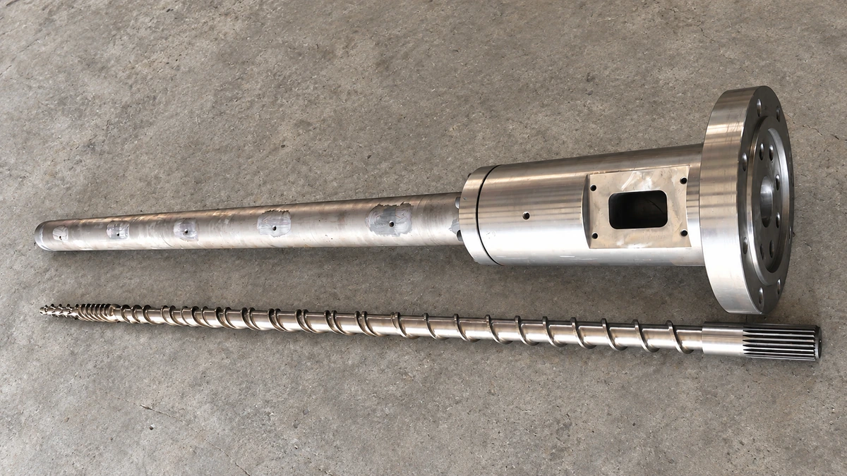
Why Your Single Screw Extruder Design Causes Extrusion Defects
Nov 13, 2026
Learn how single screw extruder design parameters—L/D ratio, compression ratio, channel depth, and mixing elements—affect melt quality, throughput, and defects.
Read Article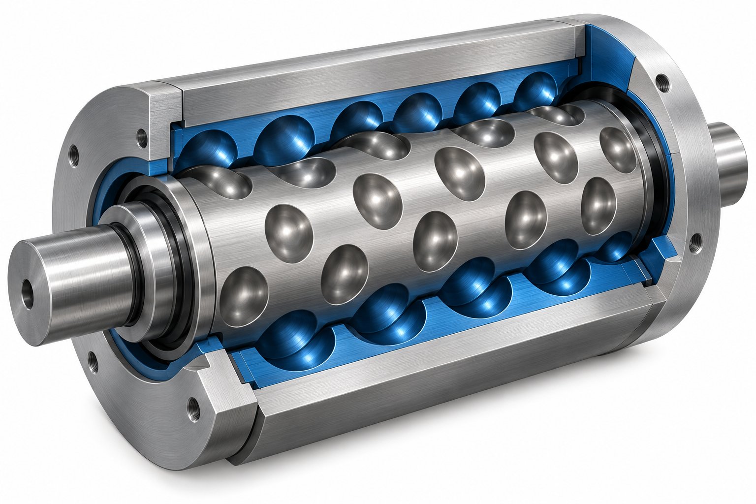
Cavity Transfer Mixer: The Blender Your Extruder Didn't Know It Needed
Nov 13, 2026
Learn how a cavity transfer mixer (CTM) upgrades single-screw extruder mixing. Covers working principles, key parameters, integration, applications, and comparisons.
Read Article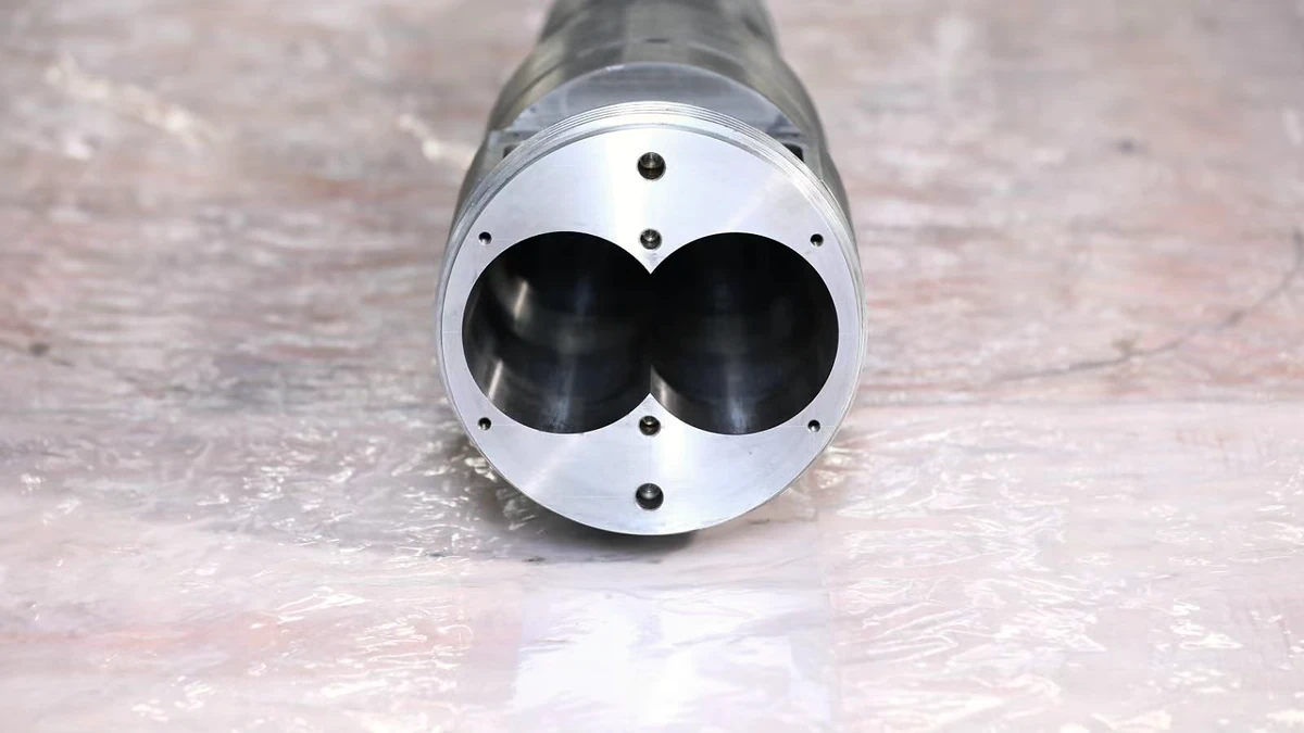
Extruder Barrel Alignment Decoded: Tolerances Most Plants Miss
Nov 13, 2026
Learn extruder barrel alignment tolerances, laser procedures, thermal offsets, and proactive schedules most plants miss — for single-screw and twin-screw lines.
Read ArticleLooking for something else?
Search by material, symptom or product and jump straight to the relevant page.
These are navigation suggestions based on keyword matching — not a quotation, not a delivery commitment, and not a substitute for engineering review. Final specification is confirmed by our engineers against your drawings and processed material.
Need help with screw barrel selection?
Share your machine model, processed material and application. Our team can help with pricing and technical support.