

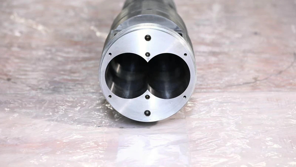
What Extruder Barrel Alignment Means and Why It Matters
Imagine a screw spinning thousands of revolutions per hour inside a barrel where the centerlines don't quite match up. Even a few thousandths of an inch of offset creates uneven metal-to-metal contact, and that subtle geometric error silently eats away at your most expensive wear components. This is the core problem that proper extruder barrel alignment prevents — and it's a problem most plants don't catch until the damage is already done.
Extruder barrel alignment is the process of verifying and correcting the geometric relationship between the barrel bore centerline and the gearbox output-shaft axis so the screw rotates concentrically within the barrel.
Why does this matter so much? When these two axes fall out of alignment, the screw rides harder against one side of the barrel bore. That asymmetric contact accelerates wear on both the screw flights and the barrel lining, increases energy consumption as the motor works against added friction, degrades melt quality through uneven shear, and dramatically shortens the service life of components that can cost tens of thousands of dollars to replace. OASIS Alignment Services notes that misalignment between these components can lead to premature barrel and screw wear, decreased throughput, poor mixing, uneven melt temperatures, and even screw breakage.
This guide serves two audiences. Plant managers will find the business justification — the real link between alignment neglect, unplanned downtime, and premature component replacement. Maintenance technicians will find actionable tolerances, step-by-step laser extruder barrel alignment procedures, and tool guidance they can apply on the shop floor. Whether you're evaluating the best bore alignment laser systems for single-barrel plastic extruders or simply trying to understand why your screw keeps wearing on one side, you'll find practical answers here.
Defining Barrel-to-Gearbox Concentricity
At its heart, barrel-to-gearbox concentricity is a straightforward geometric concept: the bore axis of the barrel must be collinear with the output-shaft axis of the gearbox within specified tolerances. Think of it like threading a needle — the screw needs to spin dead center inside the barrel, and that center is defined by the gearbox shaft driving it.
Here's where it gets critical. Even small angular or offset deviations at the gearbox end compound dramatically across the full length of the barrel. A screw-to-barrel clearance is typically minimal — roughly 0.001 in. per side, per inch of diameter — so there's very little room for error. An angular misalignment of just a few thousandths of an inch per foot, measured at the gearbox, can translate into significant offset by the time you reach the discharge end of a long-L/D barrel. That compounding effect is exactly why alignment verification requires measurements at multiple stations along the barrel length, not just at a single point near the gearbox.
Who Needs This Knowledge and Why
If you're an operator or maintenance technician, you'll recognize the symptoms firsthand: one-sided screw and barrel wear patterns visible during screw pulls, product inconsistencies you can't trace to material or die problems, and motor loads that creep upward without an obvious cause. These are the daily consequences of running a misaligned extruder.
If you're a plant manager or reliability engineer, the impact shows up differently — as unplanned shutdowns, accelerated component replacement cycles, and rising energy costs. Extruder barrel alignment services suppliers exist specifically because this problem is widespread enough to sustain an entire service industry, yet many plants still treat alignment as a one-time installation task rather than an ongoing maintenance discipline.
In the sections ahead, you'll find the root causes that introduce misalignment over time, the specific tolerance values that most plants overlook, detailed alignment procedures using both laser and mechanical methods, and guidance on when alignment correction alone isn't enough and component replacement becomes necessary.
Root Causes of Barrel Misalignment in Extrusion Lines
Misalignment rarely announces itself with a loud bang or a sudden shutdown. In most plants, it creeps in quietly — a fraction of a mil here, a slight thermal shift there — until the cumulative geometric error starts showing up as worn components, inconsistent product, or unexplained motor load increases. Understanding where these deviations originate is the first step toward preventing them. The root causes fall into two broad categories: errors introduced during installation or reassembly, and gradual drift caused by environmental and operational forces over time.
Installation and Reassembly Errors
A surprising number of alignment problems trace back to the day the extruder was first set up — or to the most recent time someone pulled the screw and put things back together. Here are the most common culprits:
- Improper shimming during initial machine setup. If the barrel supports and gearbox pedestal aren't shimmed to place the barrel bore axis and the gearbox output shaft on the same centerline, the extruder starts life misaligned. Shim packs that are the wrong thickness, incomplete, or made from compressible material will settle under load and introduce offset over time.
- Barrel flange bolt-up sequence mistakes. Tightening flange bolts unevenly or in the wrong sequence can pull the barrel off-center at the connection point. This is especially problematic on flanged barrel joints in segmented designs, where each bolt-up affects the next section's position.
- Skipping alignment verification after a screw pull or barrel change. This is arguably the most common reassembly error in the industry. Maintenance teams often assume that if they put things back the way they found them, the alignment will be fine. In practice, even careful reassembly can shift the barrel position by several mils — enough to matter.
- Relying on registration geometry that no longer holds tolerance. Many extruder designs use tight-tolerance registration fits — such as spigots, dowels, or piloted flanges — that allow the gearbox shaft axis to serve as a proxy for the barrel bore axis. This engineering assumption works well on a new machine. It breaks down when keyways wear, shafts get reground to undersize, or aftermarket gearboxes with slightly different dimensional tolerances replace the original unit. Once those registration surfaces lose their original precision, extruder barrel laser alignment verification becomes essential rather than optional.
The takeaway here is straightforward: any time the barrel-to-gearbox mechanical interface gets disturbed — whether during commissioning, maintenance, or component replacement — alignment should be re-verified before the machine goes back into production.
Environmental and Operational Drift
Even a perfectly aligned extruder on day one won't stay that way forever. The physical environment and the forces generated during normal operation gradually nudge components out of position. These drift mechanisms are subtle, which makes them easy to overlook:
- Foundation settling and concrete creep. Concrete foundations don't remain perfectly static. Over years of sustained loading, soil conditions, settlement, and geotechnical changes can shift the foundation unevenly, tilting the gearbox pedestal relative to the barrel supports. Older facilities built on fill soil or in regions with variable water tables are particularly susceptible.
- Thermal cycling fatigue on mounting surfaces. Extruder barrels routinely cycle between ambient temperature and 150-350 degrees Celsius. Each heating and cooling cycle expands and contracts the barrel, supports, and mounting hardware. Over hundreds or thousands of cycles, this repetitive stress gradually deforms mounting surfaces, loosens fasteners, and can shift the barrel's resting position relative to its original alignment baseline.
- Vibration-induced drift from adjacent equipment. Reciprocating downstream equipment — pelletizers, pullers, cutters — transmits vibration through the floor and mounting structures. Over time, this vibration can loosen hold-down bolts, shift shim packs, and gradually move the barrel or gearbox pedestal. The effect is especially pronounced when the extruder shares a common base or floor section with high-vibration equipment.
- Accidental impacts during maintenance. Overhead cranes bumping the barrel during a screw pull, forklifts nudging a barrel support, or even heavy tooling dropped on the machine frame — these events seem minor in the moment, but any lateral impact on the barrel or its supports can introduce offset that goes unnoticed until the next alignment check (if one ever happens).
What ties all these drift mechanisms together is their gradual nature. A Davis-Standard technical discussion highlights that for larger or lengthier extruders, bases are seldom rigid enough to hold the manufacturer's original alignment for a long period of time. The misalignment accumulates in tiny increments — a mil this quarter, another mil next year — until wear patterns or quality defects force someone to investigate. By that point, the barrel and screw may have already sustained significant damage.
This progressive reality is why the best bore alignment laser systems for single-barrel plastic extruders pay for themselves not just during initial commissioning, but as part of a recurring verification program. Treat alignment as a measurable, trackable parameter — one that you log, trend, and compare against baseline readings — rather than a set-and-forget installation task. A shift from reactive to proactive monitoring transforms alignment from an invisible failure mode into a managed variable, and that shift is exactly what separates plants with predictable component life from those constantly chasing premature wear.
Of course, knowing the causes is only half the equation. The real question for operators and technicians on the floor is: what does misalignment actually look like during day-to-day production, and how do you distinguish it from other common extrusion problems?
Signs and Symptoms Every Plant Operator Should Recognize
A misaligned extruder doesn't flash a warning light on the HMI screen. Instead, it leaves clues — some obvious if you know where to look, others disguised as routine process variability. The challenge is connecting what you observe during production or during a screw pull back to a geometric root cause rather than chasing material lots, die settings, or temperature profiles that aren't actually the problem.
The following diagnostic table maps the most common symptoms to their likely misalignment type and the mechanical reason each one occurs. Use it as a quick reference when troubleshooting, but keep in mind that a single symptom rarely tells the full story on its own. Patterns of multiple symptoms appearing together provide much stronger diagnostic evidence.
| Observable Symptom | Likely Misalignment Type | Mechanism |
|---|---|---|
| One-sided barrel wear (scoring or galling visible during screw pull) | Parallel offset or combined | Screw flights ride against one side of the bore along the full barrel length, creating asymmetric metal-to-metal contact |
| Tapered or wedge-shaped wear pattern (heavier at one end) | Angular | Angularity between shaft and bore axes causes the screw to press harder against the barrel wall at the end farthest from the pivot point |
| Elevated vibration at screw rotational frequency | Parallel offset or combined | Eccentric screw rotation generates a once-per-revolution radial force imbalance |
| Abnormal noise at startup or specific RPM ranges | Angular or combined | Metal-to-metal contact intensifies at certain speeds where screw whip and misalignment forces coincide |
| Higher-than-expected motor amperage at consistent process settings | Any type | Friction from screw-to-barrel contact adds parasitic load beyond what the process alone demands |
| Premature thrust-bearing or gearbox-bearing failure | Angular | Angular misalignment imposes bending moments on the drive shaft, overloading bearings designed for axial and concentric radial loads |
| Wall thickness variation in pipe or tubing | Parallel offset or combined | Off-center melt delivery to the die creates circumferential flow imbalance |
| Surface streaking or matte patches on extrudate | Combined | Uneven shear history across the melt cross-section produces regions of differing melt quality reaching the die lips |
| Inconsistent melt temperature causing gels or unmelts | Angular or combined | Misalignment changes the effective channel depth on one side of the screw, altering shear heating and residence time locally |
| Accelerated die-lip buildup | Any type | Excessive localized shear in the misaligned zone degrades polymer, producing volatile byproducts that deposit at the die exit |
Mechanical Warning Signs
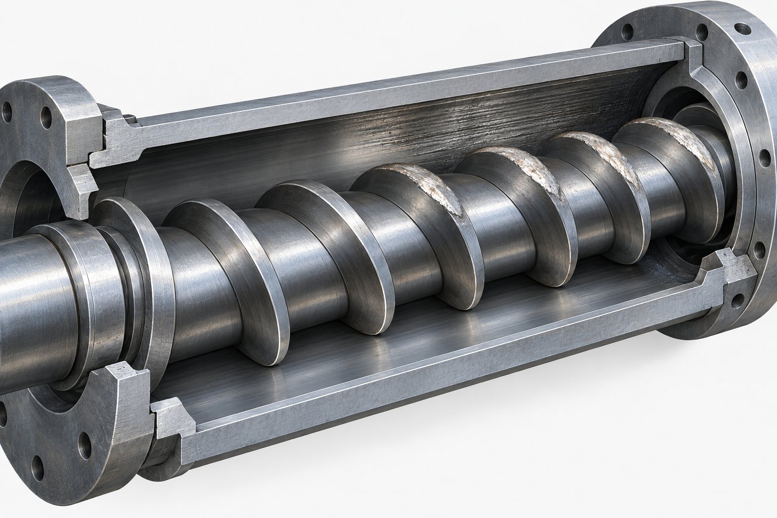
The most telling evidence usually shows up when you pull the screw. Asymmetric wear patterns — scoring concentrated on one side of the barrel bore, or galling on the screw flight tips along a single radial arc — are a direct fingerprint of misalignment. A well-aligned extruder produces relatively uniform wear around the full circumference. When you see heavy wear at the twelve o'clock position and virtually none at six o'clock (or concentrated on one lateral side), that's the barrel and screw telling you their centerlines aren't where they should be.
Between screw pulls, vibration analysis can serve as an early-detection extruder barrel alignment tool. A misaligned screw generates a characteristic once-per-revolution radial force, and a vibration sensor mounted on the barrel or gearbox housing will pick up an elevated amplitude at the screw rotational frequency. If you're already collecting vibration data as part of a predictive maintenance program, pay attention to this frequency — a rising trend is a red flag worth investigating before the next scheduled shutdown.
Motor amperage is another accessible indicator. Under consistent process conditions — same resin, same throughput, same barrel temperatures — amperage should remain stable. If you notice a gradual upward creep that doesn't correlate with material changes or temperature adjustments, the extra load may be coming from mechanical friction caused by a screw riding against the bore wall. Plastics Technology notes that wear-related performance degradation, including the higher energy input needed to maintain rate with increased flight clearance, is one of the most costly consequences of misalignment-driven screw and barrel wear.
Premature gearbox-bearing failure deserves special attention. Bearings in an extruder gearbox are engineered to handle axial thrust from melt pressure and concentric radial loads from screw weight. Angular misalignment introduces bending moments the bearings were never sized for, dramatically shortening their fatigue life. If you're replacing thrust bearings on a schedule that seems unreasonably short, misalignment should be high on the suspect list.
Product Quality Indicators Linked to Misalignment
Quality defects rooted in misalignment often masquerade as die problems or material issues, which is exactly why they persist undiagnosed for so long. Consider wall thickness variation in pipe or tubing extrusion. When the screw doesn't sit concentrically in the barrel, melt delivery to the crosshead or die adapter isn't uniform around the circumference. The result is a pipe with one wall thicker than the other — a defect that looks like a die centering issue but actually originates upstream at the barrel-to-gearbox interface.
Surface texture inconsistencies tell a similar upstream story. Streaking, matte patches, or gloss variation across the extrudate surface can develop when portions of the melt experience significantly different shear histories. In a misaligned barrel, the melt film on the "tight" side of the screw-to-barrel gap sees more intense shear than the melt on the "loose" side. These two populations of melt, with different thermal and mechanical histories, merge at the die but retain enough difference to produce visible surface defects.
Gels and unmelts — those frustrating specks and lumps in an otherwise clean extrudate — can also trace back to geometric problems. Angular misalignment effectively changes the channel depth on one side of the screw relative to the other, creating zones where resin spends less time under shear and heat. The result is incompletely melted particles passing through to the die. Meanwhile, excessive shear in the tighter zone can degrade polymer, producing the volatile byproducts that accumulate as die-lip buildup and eventually drip onto the product surface.
A word of caution here: every one of these quality symptoms has multiple possible causes. Wall thickness variation can stem from a poorly centered die mandrel. Surface streaking may originate from contaminated resin or worn die land surfaces. Gels can result from inadequate drying or incorrect screw design for the material being processed. The point isn't to blame misalignment for every defect — it's to include extruder barrel alignment verification as a standard step in your troubleshooting process rather than defaulting to die adjustments or material changes that may not address the actual root cause.
Recognizing these symptoms is valuable, but it raises an immediate practical question: how far out of alignment is too far? The answer depends on specific tolerance values that most plants either don't have on file or have never been given by their equipment supplier — a gap the next section addresses directly.
Extruder Barrel Alignment Tolerance Specifications Most Plants Overlook
That gap between "something feels off" and "here's exactly how far off it is" comes down to numbers — specific extruder barrel alignment tolerance specifications that define how much deviation is acceptable and how much isn't. Yet ask most maintenance teams for their machine's alignment tolerances and you'll get a shrug, a reference to "whatever the manual says," or silence. The tolerances exist, but they're buried in OEM installation guides that went missing years ago, or they were never communicated clearly in the first place.
Let's fix that.
Understanding Angular and Offset Tolerance Units
Before diving into the numbers, you need to speak the language. Three units show up repeatedly in extruder barrel offset and angularity tolerances:
- Mils (thousandths of an inch). The most common unit in North American plants. One mil equals 0.001 in. Offset readings between the barrel bore centerline and the gearbox shaft axis are typically expressed this way — for example, "2 mils of horizontal offset at station 3."
- mm/m (millimeters per meter). The metric equivalent for angular deviation. A reading of 0.05 mm/m means the bore axis drifts 0.05 mm for every meter of barrel length.
- Angular minutes (arcmin). One angular minute equals 1/60th of a degree. This unit quantifies the angle between the two axes directly, independent of barrel length.
Here's where the math gets important. Imagine a 1-arcminute angular error at the gearbox flange of a 120-inch (roughly 3-meter) barrel. That tiny angle translates to approximately 0.035 in. (0.9 mm) of offset at the discharge end. On a 2.5-inch extruder with a standard flight clearance of about 0.0025 in. per side, that 0.035-inch offset exceeds the total clearance by a factor of fourteen. The screw wouldn't just rub — it would gouge. This compounding effect is exactly why tighter tolerances are required for longer barrels and higher-speed applications, where centrifugal forces amplify any eccentricity.
The table below presents general industry alignment tolerance guidelines organized by extruder size range. These values reflect commonly accepted practice across OEM manuals and laser alignment service providers; however, your specific machine manufacturer's installation manual should always be the primary tolerance source. Twin screw extruder barrel alignment tolerances tend to fall at the tighter end of each range because of the additional constraint of maintaining precise center-distance spacing between the two bores.
| Extruder Size (Screw Diameter) | L/D Ratio Range | Max Parallel Offset (mils) | Max Angularity (mils/ft) | Notes |
|---|---|---|---|---|
| Small (1.0–2.5 in. / 25–65 mm) | 24:1–30:1 | 1.0–2.0 | 0.5–1.0 | Tight flight clearances make these machines highly sensitive to offset |
| Medium (2.5–4.5 in. / 65–115 mm) | 24:1–36:1 | 2.0–3.0 | 0.5–1.0 | Most common production size; tolerances tighten at higher L/D ratios |
| Large (4.5–8.0 in. / 115–200 mm) | 24:1–36:1 | 2.0–4.0 | 0.5–1.5 | Barrel sag under self-weight can mimic misalignment; verify support placement |
| Very Large (8.0–12.0 in. / 200–300 mm) | 24:1–40:1 | 3.0–5.0 | 0.5–1.5 | Foundation settling is a primary drift source at this scale |
| Twin Screw (any size) | 32:1–52:1 | 1.0–2.0 | 0.3–0.8 | Center-distance tolerance between bores adds a second critical constraint |
A few patterns stand out. Acceptable barrel bore alignment deviation values don't scale linearly with machine size — a 10-inch extruder doesn't get five times the tolerance of a 2-inch machine. The reason is that flight clearance per side follows a rough rule of 0.001 in. per inch of diameter, so larger machines have proportionally more clearance to absorb some offset. Still, the longer barrels on large extruders amplify angular errors over greater distances, which is why angularity tolerances remain tight across all size ranges.
Also note that these are general guidelines. When OEM documentation is available, use those values instead — they account for machine-specific factors like bearing design, support locations, and thermal growth assumptions that a generic table cannot capture.
When Good Enough Is Not Good Enough
Here's a trap that catches even experienced maintenance teams: treating tolerance limits as targets. A reading of 2.8 mils on a machine with a 3.0-mil maximum looks like a pass on paper. In practice, that borderline result can still accelerate wear significantly under certain conditions.
Consider a screw designed with tight flight-to-barrel clearance for high-output performance. That precision screw might have 0.002 in. of clearance per side instead of the standard 0.0025 in. — leaving even less room for geometric error. A 2.8-mil offset that's technically within the machine's general tolerance specification may consume more than half the available flight clearance on one side, effectively turning a precision machine into a wear generator.
Abrasive filled materials sharpen this effect further. When you're running glass-filled nylon or mineral-loaded polypropylene, every fraction of a mil of offset means the abrasive-laden melt gets squeezed through a tighter gap on one side and a looser gap on the other. The tight side sees concentrated abrasive contact at elevated pressure — exactly the combination that drives accelerated bore enlargement in the compression zone.
Tolerance specifications represent the maximum acceptable deviation, not a target. The goal of every alignment check should be to minimize deviation as close to zero as practical.
This distinction matters because it changes how you approach the alignment procedure. Instead of adjusting until you "pass," you adjust until further correction yields no measurable improvement. The incremental effort to go from 2.8 mils to 0.5 mils is usually minimal once the barrel is already loosened and the measurement system is set up — but the payoff in extended component life and consistent product quality is substantial.
One more practice that separates top-performing plants from the rest: documenting baseline alignment readings at commissioning. When a new barrel or gearbox is installed, take and record a complete set of offset and angularity measurements at multiple stations before the machine ever runs a production pound. That baseline becomes your reference for every future alignment check. Without it, you're comparing readings against generic tolerance tables instead of your machine's actual as-built geometry — and you'll never know whether a slight shift represents normal settling or the beginning of a progressive drift problem.
With clear tolerance targets in hand and a baseline on file, the logical next question becomes procedural: how do you actually perform the alignment measurement and correction, step by step, using the tools available in your facility?
Step-by-Step Laser Alignment Procedure for Extruder Barrels
Tolerances only matter if you can actually measure and correct to them. Yet a surprising number of plants own alignment-capable equipment and still lack a documented, repeatable procedure their maintenance teams can follow from preparation through final verification. The result is ad hoc approaches that vary from technician to technician — and inconsistent outcomes that undermine the entire point of checking alignment in the first place.
This section lays out a complete extruder barrel bore laser alignment procedure you can adapt to virtually any single-screw or twin-screw machine. Even if your facility uses mechanical methods instead of laser equipment, the fundamental sequence of establishing a reference axis, measuring deviations at multiple stations, correcting, and verifying remains the same.
Preparation and Safety Requirements
Rushing into alignment measurements without proper preparation is the fastest way to get inaccurate data — or worse, create a safety incident. Before anyone touches an alignment tool, the following prerequisites need to be complete:
- Lock out and tag out all energy sources. This includes the main drive motor, barrel heater circuits, cooling water systems, and any hydraulic screw-pull mechanisms. Verify zero energy state before proceeding. Alignment work requires personnel to reach inside the barrel bore and work close to rotating and heated components — there is no room for shortcuts here.
- Allow the barrel to cool to ambient temperature. Thermal gradients within the barrel distort bore geometry and produce false readings. A barrel that reads 40 degrees Celsius at the surface may still have significantly higher temperatures in the bore interior. Depending on the machine size, a full cool-down may take 8 to 24 hours after heaters are secured. You'll document cold-alignment values first and calculate thermal offsets separately (covered in the next section of this article).
- Remove the screw completely. The screw must be out of the barrel to allow access for laser targets, dial indicator fixtures, or optical sighting equipment inside the bore. This is also an ideal time to inspect the screw for asymmetric wear patterns — any one-sided galling or scoring provides immediate visual confirmation that misalignment has been present.
- Inspect and clean the barrel bore. Residual polymer, carbon deposits, and corrosion products inside the bore can interfere with target placement and measurement accuracy. A thorough bore cleaning with appropriate brass brushes and solvent ensures that alignment fixtures seat properly against the actual bore surface rather than against accumulated debris.
- Gather all required tools and equipment. Depending on your chosen method, this includes:
- Laser bore alignment system (emitter, targets, display unit, mounting brackets)
- Dial indicators and magnetic bases (as a backup or primary method for facilities without laser equipment)
- Precision straightedge (for gross checks before fine measurement)
- Feeler gauges (for verifying shim thicknesses and checking support contact)
- Calibrated shim stock in a range of thicknesses (stainless steel, not compressible brass or plastic)
- Torque wrench with sockets matching barrel hold-down and flange bolts
- Dial calipers or micrometer for verifying bore diameter at measurement stations
Laser Versus Mechanical Methods — Choosing Your Approach
The choice between a laser bore alignment setup for a plastic extruder and traditional mechanical methods depends on equipment availability, barrel length, and documentation requirements.
Laser bore alignment systems project a reference beam along the bore centerline and use precision targets positioned at multiple stations to measure offset and angularity relative to that beam. The advantages are substantial: setup is faster, results are displayed digitally in real time, and data can be saved electronically for trending and compliance records. As Fluke's engineering team notes, laser-based systems eliminate wire sag and optical station-shift errors that plague traditional methods, while reducing alignment time from days to hours on large equipment. For extruders with L/D ratios above 30:1, where the barrel bore stretches five feet or longer, laser systems offer a clear accuracy advantage because the reference beam doesn't sag, stretch, or drift with vibration the way a piano wire or optical sighting line can.
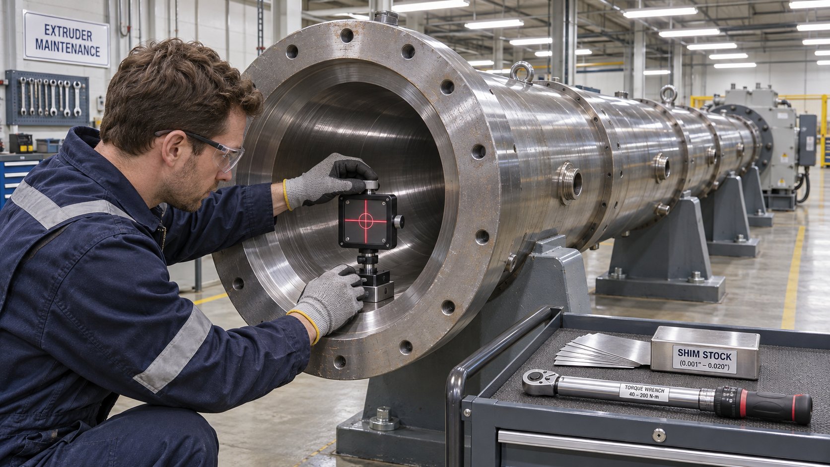
The dial indicator barrel alignment method for extruders remains a valid and widely used approach, especially in facilities that haven't invested in laser equipment. The technique involves mounting a dial indicator on a fixture attached to the gearbox output shaft (or a precision mandrel inserted in the shaft bore), then sweeping the indicator inside the barrel bore at multiple axial stations while rotating the shaft through 360 degrees. Readings at the 12, 3, 6, and 9 o'clock positions at each station define the offset in both the vertical and horizontal planes. This method requires more technician skill and patience, and it doesn't provide the digital documentation that laser systems produce automatically, but it's accurate enough for most alignment applications when performed carefully.
Wire-and-telescope methods — stretching a taut wire or using an optical telescope to establish a reference centerline — are still encountered in some plants, particularly on very large extruders. These methods work but are labor-intensive, sensitive to environmental disturbances, and require manual sag correction calculations. For most extrusion facilities, laser or dial indicator methods are more practical choices.
Regardless of which method you choose, the procedural sequence below applies. The measurement physics are the same — only the instrument generating and reading the reference line changes.
Executing the Bore-to-Shaft Alignment Sequence
With the barrel cooled, the screw out, the bore cleaned, and your measurement equipment staged, here's how to laser align an extruder barrel step by step. This sequence follows the industry-standard practice of using the gearbox output-shaft centerline as the fixed reference axis, since the gearbox position is typically the most constrained and difficult to adjust.
- Establish the gearbox output-shaft centerline as the reference axis. Insert the laser emitter (or dial indicator mandrel) into the gearbox output-shaft bore or mount it concentrically on the shaft end. The goal is to define a line in space that represents where the barrel bore centerline should be. If using a laser system, energize the laser and allow it to stabilize thermally for the manufacturer's recommended warm-up period — typically 5 to 15 minutes. Rotate the shaft (or the laser mount) through a full 360-degree sweep to confirm that the emitter is running true and not introducing its own eccentricity. Davis-Standard emphasizes that the barrel must be aligned to the drive quill of the gearbox — no exceptions — and that trying to determine alignment by leveling alone is inaccurate, as it only measures the vertical plane and doesn't reference the actual drive quill centerline.
- Position the first measurement target near the feed end of the barrel. Mount the laser target (or set up the dial indicator sweep fixture) inside the barrel bore at the first axial station, as close to the gearbox connection as practical. This station captures the initial offset and angularity at the point where the shaft enters the barrel. Record offset readings in both horizontal and vertical planes.
- Take readings at a minimum of three axial stations along the barrel length. This is a critical step that many shortcut procedures skip — and skipping it is how angular errors, parallel offsets, and barrel sag get confused with each other. Move the target to at least three positions: near the feed end, at mid-barrel, and near the discharge end. For barrels with L/D ratios above 30:1 or total lengths beyond five feet, add a fourth or fifth station for better resolution. At each station, record the horizontal and vertical offset from the reference axis.
- Calculate offset and angularity from the multi-station data. With three or more station readings, you can mathematically separate three distinct error components:
- Parallel offset — the barrel bore axis is displaced from the shaft axis by a uniform amount along its length.
- Angular error — the barrel bore axis is tilted relative to the shaft axis, producing an offset that increases linearly with distance from the gearbox.
- Barrel sag or bow — the bore deviates from a straight line between stations, indicating the barrel is deflecting under its own weight or from improper support positioning.
Most laser alignment software calculates these components automatically and displays them graphically. If you're using dial indicators, plot the readings on graph paper or a spreadsheet with axial position on the X-axis and offset on the Y-axis. A straight line through the points reveals the combined offset-plus-angularity trend; deviations from that straight line reveal sag or bow.
- Verify that the barrel is resting on its designed support points during measurement. This step sounds obvious but gets overlooked regularly. If the barrel is sitting on temporary cribbing, resting against a chain hoist strap, or missing a support roller, the bore geometry you're measuring reflects the barrel's deflected shape rather than its true alignment relative to the gearbox. Ensure all permanent barrel supports are in place, properly adjusted, and bearing the barrel's weight before recording final readings. For barrels that use sliding or roller supports to accommodate thermal expansion, confirm that the barrel is actually resting in the support saddles and hasn't shifted off-center during the screw pull.
- Adjust the barrel position to correct measured deviations. Correction is accomplished through a combination of:
- Vertical shimming — adding or removing calibrated shim stock beneath the barrel support feet or barrel mounting flanges to raise or lower the bore centerline.
- Lateral shimming — placing shims between the barrel support side faces and their mounting surfaces to move the bore centerline horizontally.
- Hold-down bolt adjustment — loosening barrel hold-down bolts, repositioning the barrel, and re-tightening in a controlled sequence.
Make adjustments at one support location at a time and re-read the affected stations after each change. Resist the temptation to adjust multiple supports simultaneously — overlapping corrections make it impossible to isolate the effect of each change and can result in chasing your own adjustments in circles.
- Re-measure all stations to confirm the correction. After making adjustments, repeat the full multi-station measurement sequence. Compare the new readings against both your tolerance specifications and, ideally, against the commissioning baseline values documented when the machine was new (or when the barrel was last replaced). If any station still exceeds tolerance, make further incremental corrections and re-measure. The goal, as discussed in the previous section, is not merely to pass the tolerance limit but to minimize deviation as close to zero as practical.
- Torque all fasteners to specification. Once the alignment readings are confirmed acceptable at all stations, torque barrel hold-down bolts, support fasteners, and flange bolts to their specified values using a calibrated torque wrench. Follow the bolt-tightening sequence specified by the OEM — typically a star pattern on flanged connections — to avoid pulling the barrel off-center during final fastening. After torquing, take one final set of readings to confirm that the tightening process itself hasn't shifted the barrel. A shift of more than 0.5 mils during torquing suggests insufficient clamping surface contact or a fastener that's binding rather than pulling straight.
- Document everything. Record the date, technician name, ambient temperature, measurement method and instrument serial numbers, readings at each station before and after correction, shim thicknesses installed, and torque values applied. This documentation serves three purposes: it provides the baseline for the next alignment check, it creates a maintenance history that can reveal progressive drift trends over time, and it supplies evidence for warranty or service claims if premature component wear occurs despite verified alignment.
Common Pitfalls That Compromise the Procedure
Even with the right equipment and a solid step-by-step process, a few common mistakes can invalidate your results:
- Measuring with only two axial stations. Two points define a line, which means you can calculate angularity and offset — but you can't detect barrel sag or bow. If the barrel is sagging between supports, a two-station measurement will show an apparent angular error that doesn't actually exist at the gearbox interface. Three stations is the minimum to separate these errors; four or more is better for long barrels.
- Ignoring thermal stabilization of the laser. Laser emitters shift beam position slightly as they warm up from ambient temperature. Taking readings before the unit has stabilized thermally introduces a systematic error that contaminates every subsequent measurement. Follow the manufacturer's warm-up specification — don't assume the laser is ready just because the display turns on.
- Failing to account for indicator or target runout. If the dial indicator fixture or laser target mount doesn't run perfectly true when rotated in the bore, the eccentricity of the fixture itself gets added to the barrel's actual offset. Check fixture runout before beginning measurements and correct or account for it mathematically.
- Taking readings with temporary supports in place. Temporary supports, jack stands, or overhead crane slings that are still bearing some of the barrel's weight will alter bore geometry. Remove all temporary support and verify the barrel is fully seated in its permanent supports before capturing final data.
A properly executed alignment procedure typically takes 4 to 8 hours for a single-screw extruder, depending on machine size, the number of stations measured, and the magnitude of correction required. That investment of time is trivial compared to the cost of a premature barrel or screw replacement — and it pays dividends every hour the machine runs afterward.
This procedure covers the single-bore-to-single-shaft geometry that applies to most single-screw machines. Twin-screw extruders, however, introduce an additional layer of geometric complexity that demands its own set of considerations — two parallel bores, segmented barrel sections, and tighter tolerances that make the alignment challenge considerably more demanding.
How Alignment Differs Between Single-Screw and Twin-Screw Extruders
Two machines can sit side by side in the same plant, run the same polymer family, and both be called extruders — yet the alignment work they demand can be vastly different. The step-by-step procedure outlined above applies cleanly to single-screw designs, where a single bore and a single output shaft define the geometric problem. Twin-screw extruders, however, multiply the complexity in ways that catch even experienced alignment technicians off guard.
Understanding these single screw vs twin screw extruder barrel alignment differences isn't academic — it determines what you measure, how you measure it, and what tolerances you hold. A technician who approaches a twin-screw segmented barrel with a single-bore mindset will miss critical error sources hiding in plain sight.
The table below maps the key alignment differences between the two machine types at a glance, followed by a deeper dive into each.
| Alignment Factor | Single-Screw Extruder | Twin-Screw Extruder |
|---|---|---|
| Number of bore-to-shaft alignments | One bore, one output shaft | Two parallel bores, two output shafts (or split-torque gear output) |
| Primary geometric constraint | Bore centerline collinear with shaft axis | Each bore collinear with its shaft axis plus precise center-distance between bores maintained along full length |
| Barrel construction | Typically one-piece or two-piece barrel | Often segmented (multiple bolted barrel sections) |
| Alignment variables per joint | Few — barrel-to-gearbox interface only | Multiple — each barrel segment joint adds offset, angularity, and center-distance variables |
| Screw intermeshing sensitivity | Not applicable | High — misalignment changes screw-to-screw clearance, risking contact between elements |
| Typical tolerance stringency | Moderate (see tolerance table in previous section) | Tighter — center-distance tolerance often held within 0.5 to 1.0 mil across full barrel length |
| Thermal growth complexity | Single bore expands radially and axially | Two bores expand and the center-distance between them changes with temperature |
| Typical measurement stations required | 3 to 5 along barrel length | At least one station per barrel segment, both bores measured independently |
Single-Screw Alignment Fundamentals
If you've followed the laser alignment procedure from the previous section, you already have a solid grasp of the single-screw scenario. The geometry is relatively straightforward: one cylindrical bore, one gearbox output shaft, one alignment problem. That simplicity is a genuine advantage. You establish the shaft centerline as the reference, measure the bore's offset and angularity at multiple stations, shim and adjust the barrel position, and verify.
Still, "straightforward" doesn't mean "trivial." Barrel length and L/D ratio impose real demands. A single screw extruder barrel concentricity check on a machine with a 36:1 L/D ratio and a 6-inch screw diameter means verifying geometric accuracy over more than 18 feet of barrel length. Small angular errors at the gearbox end compound into significant offset at the discharge end — the same compounding effect discussed in the tolerance section — which is why multi-station measurement remains non-negotiable even on machines with a single bore.
One characteristic unique to single-screw operation softens the consequences slightly: once the process is running and the screw channel fills with molten polymer, the screw effectively floats on a thin melt film between its flight tips and the barrel wall. That hydrodynamic film acts as a bearing, reducing metal-to-metal contact during steady-state operation. Alignment-related wear in single-screw machines is therefore concentrated during two vulnerable windows — startup (before the melt film develops) and shutdown (as the film collapses). During these transitions, any offset or angularity translates directly into hard contact between the screw flight OD and the barrel bore.
This melt-film cushion might sound like it lets you relax the tolerances, but it doesn't. Every startup and shutdown cycle hammers the same asymmetric contact zone, and high-speed machines with frequent cycling can accumulate thousands of these impact events per year. Abrasive filled compounds eliminate the cushion effect almost entirely, since hard filler particles embedded in the melt film act like grinding paste rather than a lubricant. The alignment still needs to be as tight as you can make it.
Twin-Screw Alignment Complexity
Imagine the single-screw problem — and then double it, add a parallelism constraint, and break the barrel into segments that each need to line up with their neighbors. That's the twin-screw alignment challenge in a nutshell, and it's why these machines demand significantly more measurement time and geometric attention.
The fundamental difference is dimensional. A twin-screw extruder has two parallel bores that must each be collinear with their respective gearbox output shaft while simultaneously maintaining a precise center-distance between them along the full barrel length. That center-distance — the spacing between the two bore centerlines — is critical because it defines the clearance between the intermeshing screw elements. If the center-distance drifts by even a mil over the barrel's length, one pair of screw elements may run tight while another pair runs loose, creating localized wear zones and uneven melt processing.
Here's what makes it especially tricky: you can have each bore perfectly aligned to its own shaft axis and still have a center-distance error. The two bores could be individually straight and true yet converge or diverge slightly along the barrel length. Catching that error requires measuring both bores independently and then comparing the center-distance at each axial station — a step that doesn't even exist in single-screw work.
Segmented Barrel Construction Adds Variables
Many twin-screw extruders — particularly co-rotating intermeshing designs used for compounding — feature modular, segmented barrel construction. Instead of a monolithic barrel, the machine uses multiple shorter barrel sections bolted together in series. This modularity is a process advantage: it lets you reconfigure vent locations, side-feeder ports, and temperature zones. From an alignment perspective, however, every barrel-section joint introduces a potential error source.
A twin screw extruder segmented barrel alignment procedure must account for each joint individually. At every section interface, the bore centerlines of the two adjacent segments must match in both the horizontal and vertical planes, and the center-distance between bores must remain consistent across the joint. A poorly torqued or contaminated flange face, a damaged registration dowel, or even a thin film of residual polymer between barrel segments can push the downstream section off-axis by fractions of a mil — small individually, but cumulative across five, eight, or twelve segments.
The practical implication? You need at least one measurement station per barrel segment, and ideally one on each side of every joint, to detect segment-to-segment misalignment. On a 48:1 L/D twin-screw compounder with twelve barrel sections, that's a minimum of twelve measurement stations per bore — twenty-four total measurements — compared to the three to five stations typical for a single-screw machine.
Co-Rotating Versus Counter-Rotating Sensitivity
Not all twin-screw designs respond to misalignment the same way. Co-rotating twin screw extruder bore alignment demands tend to be more stringent because of the intermeshing geometry. In a co-rotating machine, the screw elements engage with a wiping, self-cleaning action that depends on precise screw-to-screw clearance. Technovel's technical literature highlights that co-rotating designs develop high shear stress between the screws at the intermeshing region, and this intense interaction zone is exactly where misalignment-induced clearance changes have the greatest impact. A slight center-distance reduction in one barrel section could push intermeshing screw elements into direct contact, causing accelerated wear and potentially damaging expensive modular screw elements.
Counter-rotating designs, while still sensitive to alignment, operate with a different intermeshing geometry. Material is drawn in and compressed between the screws rather than being wiped from one screw to the other. The shear forces at the intermeshing zone are lower — making these machines somewhat more tolerant of minor center-distance variation — but they are by no means immune to alignment problems. Misalignment in counter-rotating machines manifests as uneven pressure distribution across the screw width, which can alter melt temperature uniformity and affect profile dimensions in pipe and sheet applications where these machines are commonly used.
When Alignment Alone Isn't the Answer
Twin-screw machines present a particular challenge at the intersection of alignment and wear. Because tolerances are tighter and intermeshing clearances are smaller, bore wear that might be tolerable on a single-screw machine can push a twin-screw extruder past the point where realignment alone restores acceptable geometry. If the bore diameter in one or more barrel segments has enlarged beyond the point where center-distance can be corrected through shimming, or if screw element OD has worn enough to eliminate the wiping action, the problem has moved from an alignment issue to a component replacement issue.
Recognizing that transition point requires dimensional data — actual measured bore diameters, screw element ODs, and center-distance readings compared to original specifications. For plants evaluating whether bore or screw wear has progressed beyond what alignment correction can address, a component-focused dimensional assessment is a logical next step. NANHAIYA's screw-and-barrel evaluation process covers both single-screw and twin-screw equipment, reviewing machine drawings, photos, and measured dimensions to assess whether custom or replacement screw barrels are warranted. This kind of component-level review helps determine whether the wear pattern you're seeing is correctable through realignment or whether new components are needed to restore proper clearances. It's worth noting that this is a component evaluation and supply service — not an on-site alignment service — so it complements rather than replaces the alignment work your maintenance team or alignment contractor performs.
Whether your plant runs single-screw or twin-screw equipment, one variable complicates every alignment reading discussed so far: temperature. The tolerances and procedures covered to this point assume a cold barrel at ambient conditions. In reality, your barrel spends the vast majority of its operating life at temperatures hundreds of degrees above ambient — and steel doesn't sit still when it gets hot.
Thermal Expansion and Hot Versus Cold Alignment Methods
Every tolerance value, every laser reading, and every shim adjustment discussed so far shares one limiting assumption: the barrel was cold. At ambient temperature, a steel barrel sits in a dimensionally stable state that's convenient for measurement — but it's not the state the machine spends most of its life in. The moment you energize the heaters and bring the barrel up to processing temperature, the geometry you so carefully verified starts to change.
Why Cold Alignment Readings Do Not Tell the Whole Story
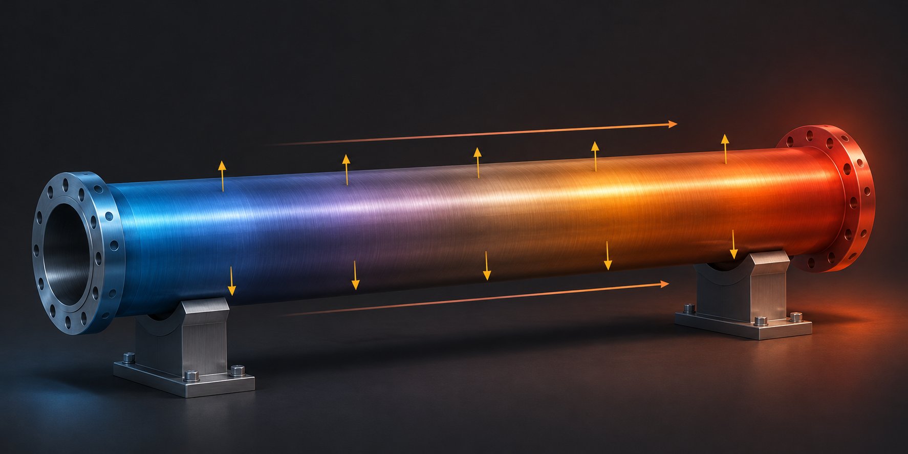
Steel expands when heated. That's not a surprise to anyone who has worked around extrusion equipment, but the magnitude and practical consequences of that expansion often catch maintenance teams off guard. A typical extrusion barrel operating between 150 and 350 degrees Celsius experiences substantial thermal growth in both the axial and radial directions. The governing relationship is straightforward — thermal growth equals the temperature differential multiplied by the component length multiplied by the material's coefficient of thermal expansion. For carbon steel, that coefficient is approximately 6.5 x 10⁻⁶ in/in/°F (roughly 12 x 10-6 mm/mm/°C).
Imagine a 120-inch nitrided steel barrel heated from a 70°F shop ambient to a uniform 500°F operating setpoint. The temperature differential is 430°F. Plugging into the thermal growth formula:
Growth = 120 in. x 430°F x 6.5 x 10⁻⁶ in/in/°F = approximately 0.336 in. of axial elongation.
That's over a third of an inch of length change — and it doesn't happen uniformly. Different barrel zones run at different temperature setpoints. The feed section might sit at 350°F while the metering section reaches 550°F, creating a thermal gradient along the barrel that produces uneven axial growth. Radially, the barrel OD heats faster than the bore surface in some configurations, introducing temporary bowing during heat-up that may or may not resolve at steady state.
Here's where the extruder barrel thermal expansion alignment offset problem gets real. If barrel supports are rigidly fixed — bolted tightly to a steel base with no provision for axial movement — the barrel has nowhere to grow. It pushes against the restraints, and something has to give. The barrel may bow upward or sideways between supports, the mounting hardware may deform, or the barrel may shift laterally at a support that loosens under the thermal load. Any of these responses alters the bore centerline position relative to the gearbox shaft, effectively undoing the cold alignment you verified the day before.
Even with properly designed sliding supports that accommodate axial growth, radial expansion changes the barrel's effective centerline height. A 6-inch-OD barrel heated 400°F above ambient grows roughly 0.016 in. in diameter — meaning the bore centerline rises about 0.008 in. relative to the support saddle. That might sound trivial, but recall that tight-tolerance small extruders have maximum allowable offsets of only 1 to 2 mils. An 8-mil vertical shift from thermal growth alone can exceed the total tolerance budget multiple times over.
Thermal Growth Compensation: Setting a Deliberate Cold Offset
The solution isn't to align at operating temperature — that's impractical for reasons we'll get to in a moment. Instead, experienced alignment technicians use thermal growth compensation by intentionally setting a calculated misalignment during cold alignment that resolves to correct alignment once the barrel reaches steady-state temperature.
The concept is identical to what pump and rotating-equipment engineers call a "thermal offset." As industrial alignment engineering resources explain, you position the cold machine with a deliberate offset — equal in magnitude but opposite in direction to the predicted thermal growth — so that expansion during operation brings the components into true alignment. For an extruder barrel whose bore centerline will rise 8 mils when hot, you'd set the cold alignment 8 mils low relative to the gearbox shaft axis. When the barrel heats up and grows, those 8 mils of vertical rise bring the bore centerline right where it needs to be.
Calculating the offset requires three pieces of information for each barrel support location:
- Temperature differential (ΔT). The difference between the expected steady-state operating temperature at that barrel zone and the ambient temperature during the cold alignment measurement.
- Height from support base to bore centerline. This is the dimension that thermal growth acts on vertically. A taller barrel-to-support geometry amplifies the vertical centerline shift.
- Coefficient of thermal expansion for the barrel alloy. Carbon steel, nitrided steel, and bimetallic barrel liners each expand at slightly different rates. Use the value for the dominant structural material — typically the barrel body alloy.
Multiply these three values together, and you have the predicted vertical growth at that support point. Repeat the calculation for horizontal growth if lateral thermal movement is expected (common when the barrel is constrained asymmetrically). The net offset at each support station defines the cold-alignment target values that replace "zero" as the goal.
A practical caution: how thermal cycling affects extruder barrel alignment isn't limited to a single heat-up event. Repeated cycling between cold and operating temperature fatigues support hardware, loosens bolted connections, and can progressively shift the barrel's resting position. Over hundreds of thermal cycles, the barrel's actual hot alignment may drift away from the original prediction, even if the cold alignment hasn't visibly changed. This is one reason alignment verification belongs on a recurring maintenance schedule rather than being treated as a one-time commissioning task.
Practical Hot-Alignment Verification
If cold alignment with a thermal offset is the primary method, how do you verify that the prediction actually works once the barrel is at temperature? This is where hot vs cold barrel alignment for plastic extruders gets complicated — because the tools that work beautifully in a cold bore become useless inside a barrel at 500°F.
Standard laser bore alignment systems use optical targets and precision-mounted components that cannot survive sustained exposure to extrusion processing temperatures. Inserting a laser target into a barrel running at 250 to 350 degrees Celsius would damage the equipment and produce meaningless readings from thermally distorted target housings. Dial indicators face the same limitation — the magnetic bases lose holding force at elevated temperatures, and the indicator mechanisms themselves are rated for use well below extrusion barrel temperatures.
So what can you actually do? Several practical approaches provide indirect but useful verification:
- Infrared surface temperature mapping. Using a calibrated infrared thermometer or thermal imaging camera, measure the barrel surface temperature profile at multiple circumferential positions and axial stations while the machine is at steady-state operating temperature. Asymmetric temperature distributions — one side of the barrel significantly hotter or cooler than the other — can indicate that the screw is riding against the bore wall on the hot side, creating frictional heating that confirms a residual alignment error at operating conditions.
- Motor load symmetry analysis. Monitor motor amperage as the machine runs at steady-state conditions. Compare the load profile at different screw speeds. A misaligned barrel at operating temperature will often show a characteristic amperage increase at higher screw speeds where centrifugal forces push the screw harder against the bore wall on the offset side. Stable, predictable motor loads across the speed range suggest the thermal offset calculation is working as intended.
- Wear pattern analysis as retrospective confirmation. The ultimate proof of hot-alignment accuracy is what you see the next time you pull the screw. Uniform, symmetric wear around the full circumference of both the screw flights and the barrel bore indicates that the operating alignment was correct. One-sided wear patterns — especially if they differ in location from the cold-alignment offset direction — suggest the thermal growth prediction needs refinement.
- External dimensional monitoring. On some large extruders, it's feasible to mount external dial indicators or displacement sensors on the barrel supports to track how much the barrel actually moves during heat-up. Comparing the measured movement to the predicted thermal growth validates or corrects your expansion calculations for future alignment work.
The most robust approach combines calculation and observation. Establish your cold-alignment baseline data with precise laser measurements. Calculate the expected thermal growth at each support point using the barrel alloy's coefficient of expansion and the zone-by-zone temperature differential. Apply those offsets during cold alignment. Then verify the prediction indirectly through motor load trending, thermal imaging, and screw-pull wear inspections over the following production campaign. Document both the cold readings and the estimated hot-alignment state for each machine so future technicians have a complete picture rather than half the story.
This documentation habit is especially valuable when comparing results across multiple alignment cycles. If your thermal offset prediction consistently overcorrects in the vertical plane — suggested by wear patterns shifting from the top of the bore to the bottom — you can refine the calculation by adjusting the assumed temperature differential or accounting for support compliance that absorbs some of the growth. Each alignment cycle becomes a data point that improves the accuracy of the next one.
Thermal growth, of course, doesn't act on the barrel in isolation. The supports that carry the barrel's weight and guide its expansion play an equally critical role in determining whether the bore centerline ends up where you predicted — or somewhere else entirely. Choosing the wrong support type, spacing supports incorrectly, or ignoring thermal movement provisions can introduce errors that no amount of shimming at the gearbox end will fix.
Barrel Support Systems and the Full Alignment Ecosystem
A perfectly calculated thermal offset and a flawless set of laser readings at the gearbox interface mean nothing if the barrel is sagging between two supports spaced too far apart — or binding against a support that won't let it slide when heat arrives. The barrel support system is the structural backbone that holds every alignment correction in place, and it's one of the most neglected components in the entire extrusion line. Worse, its failures mimic the exact same symptoms as gearbox-to-barrel misalignment — asymmetric wear, elevated motor load, product variation — making it easy to chase the wrong root cause for months.
The extruder barrel support system alignment role extends beyond simply holding the barrel's weight. Supports define the barrel's vertical position, resist lateral displacement, and — critically — must allow the barrel to expand and contract freely along its axis as heater zones cycle on and off. Get any one of those functions wrong, and the bore centerline drifts away from the gearbox reference axis no matter how carefully you shimmed the gearbox end.
Types of Barrel Supports and Their Alignment Role
Not all barrel supports work the same way, and selecting the wrong type for your machine's operating conditions is a surprisingly common source of alignment trouble. Three basic designs cover the majority of installations:
Fixed pedestal supports bolt rigidly to the machine base and clamp the barrel at a specific axial location. They provide excellent vertical and lateral stability but offer zero accommodation for thermal growth. These supports are typically used at only one location — usually closest to the gearbox — to serve as the barrel's fixed anchor point. Every other support along the barrel length must allow movement, because the barrel will grow away from this fixed reference as it heats. When plants mistakenly install fixed pedestals at multiple locations, the barrel has nowhere to expand and will bow or shift laterally under thermal load, as Jim Frankland details in Plastics Technology: if the barrel cannot expand in a straight line, it will bend — and the resulting screw flex causes galling, rapid wear, and eventual screw breakage from repeated reverse flexure.
Roller supports cradle the barrel in a saddle mounted on cylindrical rollers that allow axial sliding as the barrel grows during heat-up. They handle the weight well and accommodate thermal movement in the axial direction, but they provide limited resistance to lateral displacement. On longer barrels or machines subject to vibration from nearby equipment, a roller support that lacks lateral guides can allow the barrel to slowly walk sideways — introducing a horizontal offset that compounds the alignment error at the gearbox interface.
Sliding supports use a flat or V-shaped saddle with a low-friction contact surface — often brass or PTFE-lined — that accommodates both axial thermal movement and minor lateral shifts. These are the most versatile design for mid-barrel positions and are the type recommended by most OEMs for larger extruders. Davis-Standard specifically notes that support joints should be made from non-corrosive materials such as brass to prevent "freezing" of the support, and that the entire support structure must be rigid enough to maintain its position rather than tipping over as the barrel expands.
Choosing the right support type and placement depends on several interrelated factors:
- Barrel weight. Heavier barrels (large-diameter, bimetallic-lined) need supports with higher load ratings and broader saddle contact areas to distribute the load without point-loading the barrel OD.
- Barrel length and L/D ratio. Longer barrels require more support points to prevent sag between supports. The spacing must keep the unsupported span short enough that the barrel's own weight doesn't deflect the bore centerline beyond alignment tolerance.
- Operating temperature range. Higher processing temperatures produce more axial growth, demanding supports with greater sliding travel. A support designed for 200°C commodity resin processing may not have enough travel range for a 350°C engineering-resin application on the same machine.
- Thermal growth direction. Growth radiates axially away from the fixed anchor point. Supports closer to the discharge end see the most cumulative movement and need the most sliding freedom. Placing a high-friction or restricted-travel support at the far end of the barrel is a recipe for barrel sag correction problems on plastic extruder lines.
A quick field check can tell you whether your supports are doing their job. When the extruder is cold, place a precision level on each support and note the reading. Heat the machine to full operating temperature and check again. Any noticeable tilt indicates the support has been pushed over by thermal forces rather than allowing the barrel to slide freely. You can also inspect the slide marks — the polished contact tracks on the barrel OD where it moves through each support saddle. Those marks should be proportional to the calculated thermal expansion at each support location. If one support shows no slide marks at all while the next one shows heavy scoring, you have a stuck support forcing the barrel to accommodate all the growth at a single point — a condition that produces complex bending worse than a gradual bow.
Beyond the Barrel — Feed Throat, Die, and Downstream Alignment
It's tempting to think of extruder barrel alignment as beginning and ending at the gearbox flange. In reality, the barrel exists within a chain of geometric relationships that extends from the hopper throat all the way through the die and downstream calibration equipment. Correcting alignment at one link while ignoring the rest limits the benefit you'll see in wear reduction and product quality.
Feed throat to barrel alignment is the first link in that chain. The feed throat bolts to the barrel's entry end and houses the transition from hopper to barrel bore. If the feed throat bore isn't concentric with the barrel bore, the screw passes through a localized step or offset at the feed zone — creating a wear point and a potential hang-up zone for pellets. Feed throat alignment to the barrel entry in extrusion is typically controlled by registration fits (piloted flanges or dowel pins), but these features wear over time, especially on machines that see frequent screw pulls. Verifying feed throat concentricity during a barrel alignment check adds minimal time and catches a problem that's otherwise invisible until you see localized scoring at the feed zone during the next screw pull.
Barrel-to-die adapter concentricity sits at the opposite end. The adapter or breaker-plate housing connects the barrel discharge to the die body. Any offset here introduces an eccentric flow path between the barrel bore and the die's entry channel, which disrupts melt distribution even if the die itself is perfectly centered. On machines where the die is removed and reinstalled frequently — for product changeovers, screen changes, or die cleaning — the adapter interface is particularly vulnerable to wear-induced looseness and accumulated shimming errors.
Downstream equipment alignment to the extruder die centerline is the final and most frequently overlooked link. The calibration table (sizing sleeve or vacuum tank), puller, and cutter all need to be aligned to the die's exit centerline so the extrudate travels in a straight path from die lips to takeoff. Even a small angular deviation between the die exit and the calibration table entrance forces the still-soft extrudate into a bend, causing wall thickness eccentricity in pipe, sheet gauge variation, or profile distortion. Plants that invest in precise barrel alignment but neglect downstream equipment alignment to the extruder die centerline often find that their product quality improvements plateau short of expectations — the upstream geometric accuracy is being erased by a crooked calibration table two feet past the die.
A practical way to think about this: alignment is a system property, not a component property. The bore-to-gearbox interface gets the most attention because it has the most dramatic wear consequences, but the geometric chain from feed throat to puller determines the final product geometry. During any scheduled alignment verification, walk the full chain. Check feed throat registration, verify the die adapter seating surface for wear or distortion, and shoot a laser or string line from the die face to the calibration table entrance. The incremental time is small; the incremental insight is substantial.
One important caveat deserves emphasis. Die-related flow defects — land mark streaks, spider lines, uneven flow distribution across a sheet die — originate in the die's internal flow geometry, not in the barrel or its supports. These defects require their own diagnostic process involving die disassembly, land measurement, and flow simulation. Attributing every surface defect to barrel alignment is just as counterproductive as ignoring alignment entirely. The goal is to verify alignment as one variable in a broader system and then move to the next variable with confidence that the geometric foundation is solid.
With the full alignment chain understood — from gearbox shaft through barrel supports, feed throat, die adapter, and downstream equipment — the remaining question isn't how to align, but when. Turning alignment from a reactive repair after wear is discovered into a proactive, scheduled discipline is what separates plants that manage component life predictably from those that are perpetually surprised by premature failures.
Proactive Alignment Scheduling and Knowing When to Replace Components
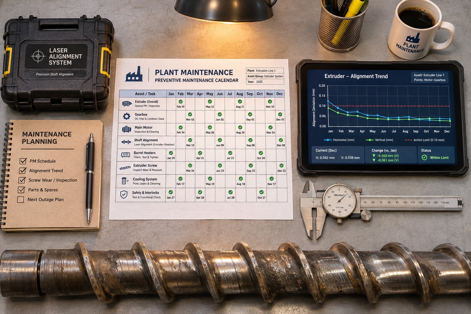
Most plants don't check alignment until something breaks — a screw snaps, a barrel wears through its liner, or product quality degrades to the point where customers start rejecting shipments. By then, the damage is already thousands of dollars deep and the unplanned downtime is eating into delivery schedules. Shifting from that reactive posture to a proactive extruder alignment check frequency takes surprisingly little effort once you know what events should trigger a verification and what to do when the numbers tell you alignment alone won't solve the problem.
Building an Alignment Check Schedule
Think of alignment verification the way you think about oil changes on a vehicle. You don't wait for the engine to seize — you change the oil at regular intervals and after specific events that stress the system. The same logic applies here. An extruder barrel alignment preventive maintenance schedule should be event-driven first and calendar-driven second, because the events that disturb alignment don't follow a neat annual cycle.
The table below lists the triggers and recommended frequencies that form the backbone of a practical schedule. Adapt the intervals to your plant's specific utilization rates and operating environment, but treat the event-based triggers as mandatory checkpoints.
| Trigger Event or Condition | Recommended Action | Rationale |
|---|---|---|
| Initial commissioning of new or rebuilt extruder | Full multi-station laser alignment and baseline documentation | Establishes the reference dataset every future check will be compared against |
| After every screw pull and reinstallation | Verify alignment at minimum three stations before restarting production | Screw removal and reinsertion can shift barrel position, especially if supports were disturbed |
| After barrel replacement or barrel section change (twin-screw) | Full alignment procedure with new baseline documentation | New barrel dimensions may differ slightly from the original; registration fits may not replicate prior geometry exactly |
| After gearbox service, rebuild, or replacement | Full alignment from gearbox output shaft through discharge | Gearbox shaft centerline defines the reference axis — any change there invalidates the entire alignment chain |
| After foundation repair, grouting, or mounting modification | Full alignment with updated baseline | Foundation changes alter the spatial relationship between gearbox pedestal and barrel supports |
| Annual check for high-utilization machines (5,000+ hours/year) | Multi-station verification compared to baseline | Catches progressive drift from thermal cycling, vibration, and foundation creep before wear becomes visible |
| Biennial check for moderate-utilization machines (<5,000 hours/year) | Multi-station verification compared to baseline | Lower thermal cycle count reduces drift rate, but environmental factors still accumulate |
| Asymmetric wear discovered during screw pull inspection | Immediate alignment check before installing replacement or refurbished screw | One-sided wear is direct physical evidence that misalignment is present; installing a new screw without correcting alignment will reproduce the same wear pattern |
| Unexplained rise in motor amperage at constant process conditions | Schedule alignment verification at next available downtime | Parasitic friction from screw-to-barrel contact increases drive load — one of the earliest detectable symptoms |
| After significant impact event (crane contact, forklift bump, seismic activity) | Spot-check alignment at feed end and discharge end within 48 hours | Lateral impacts can shift barrel or support position instantly, creating sudden onset misalignment |
Here's the principle that ties all these triggers together: a complete alignment verification on a typical single-screw extruder takes four to eight hours. An unplanned shutdown caused by a cracked screw or a worn-through barrel liner takes days — plus the cost of emergency parts, expedited shipping, and lost production. The math is overwhelmingly in favor of scheduled checks. As proactive maintenance frameworks emphasize, aligning PM frequencies with equipment criticality and failure history is the key to reducing both cost and breakdown risk over time.
One practical tip: integrate alignment checks into your existing preventive maintenance software or CMMS work order system. Create a recurring task tied to each extruder's asset record, with event-based triggers linked to screw-pull work orders and gearbox service orders. When a technician closes a screw-pull work order, the system automatically generates an alignment verification task. This removes the reliance on institutional memory — the check happens because the system demands it, not because someone remembers to request it.
Knowing When Components Need Replacement Rather Than Realignment
Every alignment check doubles as a wear inspection opportunity, and sometimes what the measurements reveal goes beyond what shimming and repositioning can fix. You'll encounter situations where the bore diameter has enlarged past tolerance, the screw flight OD has worn to the point where clearance can't be restored by alignment alone, or the barrel's bimetallic liner has eroded through to the base metal. At that point, the question shifts from "how do I realign this?" to "when to replace extruder barrel vs realign?"
Several measurement-based indicators signal that you've crossed the threshold from alignment correction into component replacement territory:
- Bore diameter exceeds nominal plus maximum allowable wear. Industry guidelines from Plastics Technology indicate that flight clearance beyond four times the original new-screw clearance generally warrants replacement — though critical-duty processes such as medical tubing may demand action at twice the new clearance. If your bore ID measurements show enlargement that places flight clearance beyond these thresholds even with the screw centered perfectly, no amount of alignment correction will restore performance.
- Screw flight hard facing is completely worn through. The hard-facing layer on screw flight tips is typically about 0.060 in. thick. Once it's gone, the softer base metal wears at an accelerated rate. A screw in this condition will degrade rapidly regardless of how well the barrel is aligned. As a general rule, a screw should never be refurbished more than three times, because repeated welding of new hard facing onto the base material deteriorates the bond and increases the risk of delamination.
- Barrel liner damage or delamination. Bimetallic barrel liners have a finished thickness of approximately 0.060 in. If bore measurements or borescope inspection reveal that the liner has worn through to the backing steel in localized zones, the barrel needs relining or replacement — the alignment is secondary to the metallurgical integrity of the bore surface.
- Center-distance deviation in twin-screw barrels exceeds correction range. On segmented twin-screw machines, bore wear in individual segments can change the center-distance between the two bores. If that deviation exceeds what shimming at the segment joints can correct, the worn segment needs replacement to restore proper screw intermeshing clearance.
When an extruder screw and barrel wear assessment after alignment reveals these conditions, obtaining a dimensional evaluation from a specialist is a practical next step. NANHAIYA's screw-and-barrel evaluation process reviews machine information, drawings, photos, and measured dimensions to assess whether custom or replacement screw barrels are warranted for existing production lines — covering both single-screw and twin-screw configurations. This component-matching approach complements alignment work by ensuring that replacement parts meet the dimensional and plasticizing requirements of the specific extruder rather than relying on generic catalog dimensions that may not account for your machine's actual bore condition or process demands.
An important qualifier: replacement screw barrels address component wear, not every product defect. Flow distribution issues, surface streaking originating in the die, and melt temperature instability caused by incorrect screw design or process settings won't be solved by new hardware alone. The diagnostic discipline discussed throughout this article — verifying alignment, inspecting supports, checking the full geometric chain from feed throat to downstream equipment — remains necessary even after installing fresh components. New parts in a misaligned machine will simply wear out again on the same accelerated schedule.
That feedback loop is the final and most important point. Alignment verification, wear assessment, and component replacement aren't three separate activities — they're stages in a continuous cycle. Each alignment check produces dimensional data that informs the next wear assessment. Each wear assessment determines whether realignment is sufficient or replacement is needed. And each component replacement resets the geometric baseline, demanding a fresh alignment verification before the machine returns to production. Plants that run this cycle deliberately, on a defined schedule, manage their extruder investments proactively. Those that don't are left reacting to failures they could have predicted — and prevented — months earlier.
Frequently Asked Questions About Extruder Barrel Alignment
1. How often should extruder barrel alignment be checked?
Alignment should be verified after every screw pull and reinstallation, after any gearbox or barrel replacement, and following foundation modifications. High-utilization machines running more than 5,000 hours per year benefit from an annual multi-station check, while moderate-utilization lines should be verified at least every two years. Event-based triggers — such as asymmetric wear found during a screw inspection, unexplained motor amperage increases, or physical impact events like crane or forklift contact — should prompt an immediate verification regardless of the calendar schedule.
2. What tools are needed for extruder barrel laser alignment?
A complete laser bore alignment setup typically includes a laser emitter, precision bore targets, a digital display or software interface, and mounting brackets sized for the barrel bore and gearbox shaft. Supporting tools include calibrated stainless-steel shim stock, a torque wrench with appropriate sockets, feeler gauges, and dial calipers for bore diameter verification. Dial indicators with magnetic bases serve as a valid backup or primary method for plants without laser equipment. The laser approach offers faster setup, real-time digital readings, and automatic documentation — advantages that become especially significant on barrels with L/D ratios above 30:1.
3. What is an acceptable alignment tolerance for an extruder barrel?
Acceptable tolerances vary by extruder size and type. Small extruders (1.0-2.5 in. screw diameter) typically allow 1.0-2.0 mils of parallel offset and 0.5-1.0 mils per foot of angularity. Medium machines (2.5-4.5 in.) permit 2.0-3.0 mils of offset. Twin-screw extruders require tighter values — usually 1.0-2.0 mils of offset and 0.3-0.8 mils/ft of angularity — because center-distance between the two bores adds a critical second constraint. Always defer to OEM specifications when available, and treat these limits as maximums rather than targets.
4. How does thermal expansion affect extruder barrel alignment?
Steel barrels expand both axially and radially when heated from ambient to processing temperatures of 150-350 degrees Celsius. A 120-inch barrel heated 430 degrees Fahrenheit above ambient can elongate roughly 0.336 inches. Radial growth raises the bore centerline relative to the support saddle, potentially exceeding tight alignment tolerances on small extruders. Experienced technicians compensate by applying a calculated cold offset — intentionally setting the barrel low or laterally displaced at cold conditions so thermal growth brings the bore centerline into true alignment at steady-state operating temperature.
5. When should an extruder barrel be replaced instead of realigned?
Replacement becomes necessary when bore diameter has enlarged beyond the maximum allowable wear limit — generally when flight clearance exceeds four times the original new-screw clearance, or twice that value for critical applications like medical tubing. Other replacement indicators include bimetallic liner worn through to the base steel, screw flight hard facing completely eroded, or twin-screw barrel segments with center-distance deviation beyond what shimming can correct. A specialist such as NANHAIYA can review machine drawings, photos, and measured dimensions to evaluate whether custom or replacement screw barrels are warranted for the specific extruder configuration.
Written by
Nanhaiya Technical Team
Zhoushan Nanhaiya Plastic Machinery Co., Ltd.
The Nanhaiya technical team supports screw and barrel manufacturing projects through application review, technical communication, custom manufacturing coordination, and production and quality control.
Discuss Your Application
Related Articles
More insights on screw barrel technology and plastics processing.
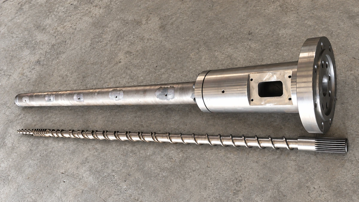
Why Your Single Screw Extruder Design Causes Extrusion Defects
Nov 13, 2026
Learn how single screw extruder design parameters—L/D ratio, compression ratio, channel depth, and mixing elements—affect melt quality, throughput, and defects.
Read Article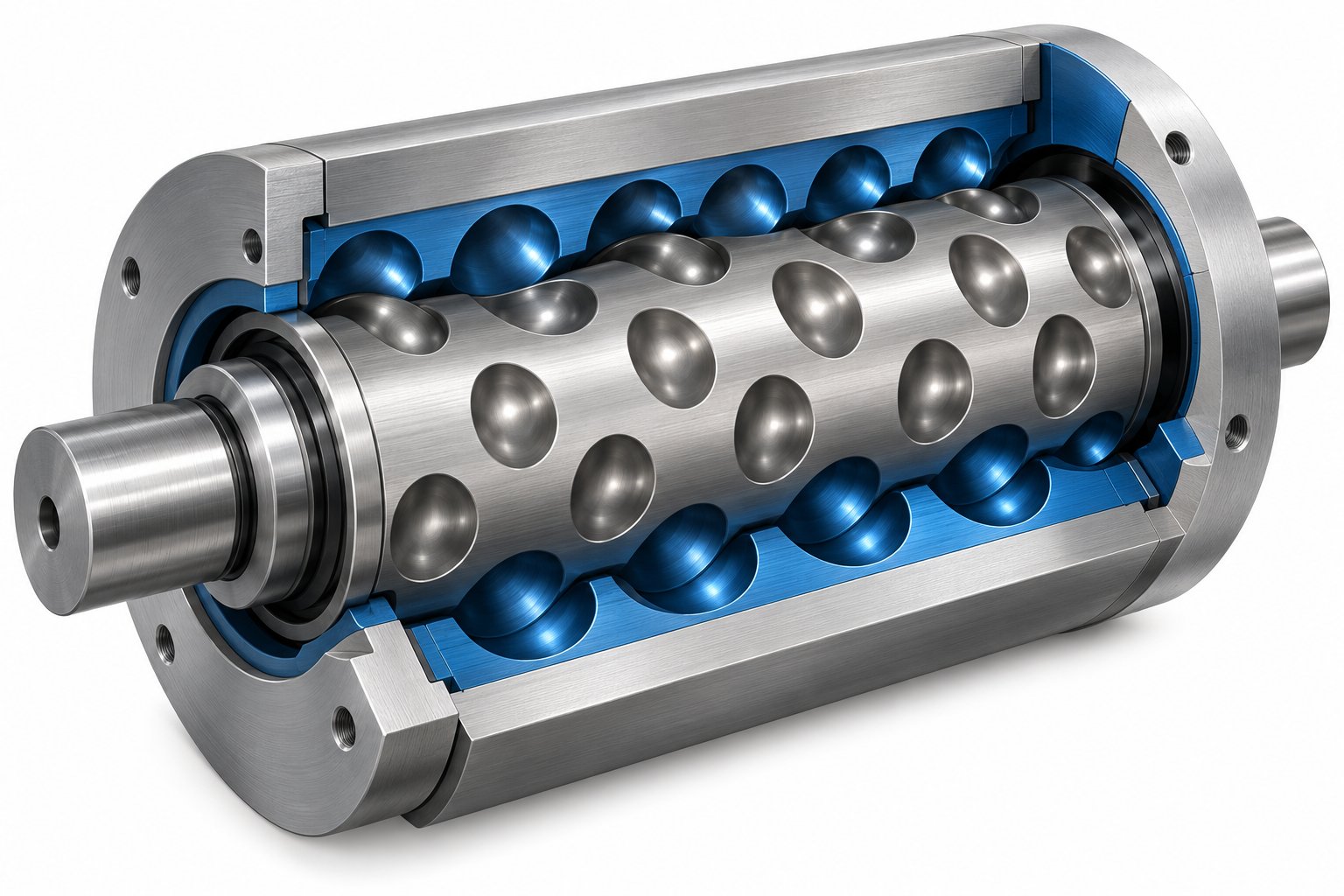
Cavity Transfer Mixer: The Blender Your Extruder Didn't Know It Needed
Nov 13, 2026
Learn how a cavity transfer mixer (CTM) upgrades single-screw extruder mixing. Covers working principles, key parameters, integration, applications, and comparisons.
Read Article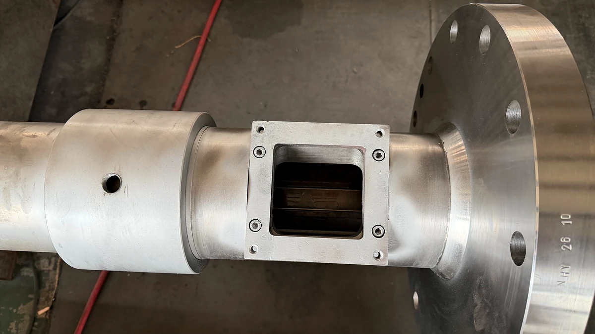
Vent Stuffer Decoded: End Vent Flow and Reclaim Lost Throughput
Nov 12, 2026
Learn what a vent stuffer is, how it prevents vent flow in twin-screw extruders, and how to size, optimize, and maintain one for peak devolatilization performance.
Read ArticleLooking for something else?
Search by material, symptom or product and jump straight to the relevant page.
These are navigation suggestions based on keyword matching — not a quotation, not a delivery commitment, and not a substitute for engineering review. Final specification is confirmed by our engineers against your drawings and processed material.
Need help with screw barrel selection?
Share your machine model, processed material and application. Our team can help with pricing and technical support.