

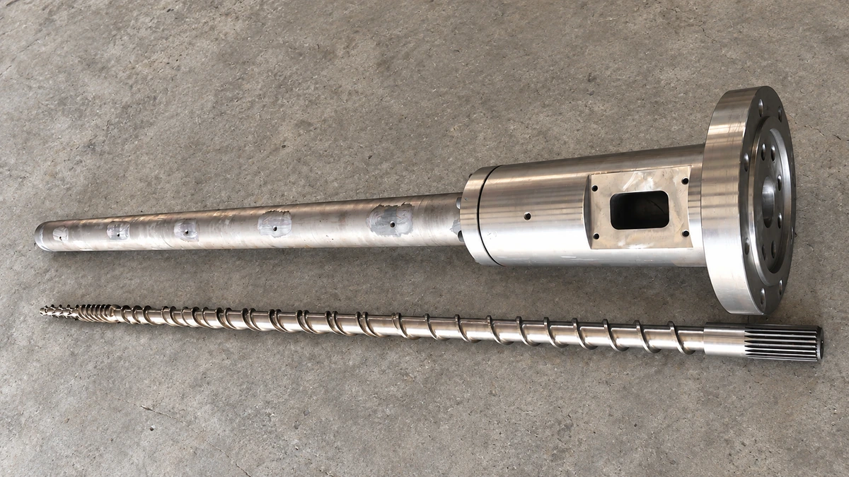
What Single Screw Extruder Design Really Means
Imagine running a production line where output surges unpredictably, melt temperatures drift out of spec, and finished parts show gels or surface defects. You adjust barrel heaters, swap die plates, tweak screw speed—yet the problems persist. More often than not, the root cause sits inside the barrel itself: the extruder screw. Its geometry quietly dictates almost everything that happens between the hopper and the die lip.
Defining Single Screw Extruder Design
Single screw extruder design is the engineering discipline of specifying screw geometry—L/D ratio, compression ratio, channel depths, flight dimensions, and mixing elements—to convert raw polymer into a homogeneous melt at controlled output and quality.
That definition sounds compact, but every parameter embedded in it carries real consequences on the shop floor. The L/D ratio sets how much barrel length the polymer has to absorb energy and reach thermal equilibrium. The compression ratio governs how aggressively the solid bed is compacted and melted. Channel depths determine shear rates and residence times. Flight width and clearance control leakage flow—the backward seepage of melt over the flight lands that erodes pumping efficiency. And mixing elements, when present, decide whether the melt emerges with uniform temperature and composition or with hot spots and unmixed pockets. Every one of these variables is a deliberate engineering choice, not a manufacturing default.
Why Screw Geometry Governs Extrusion Performance
Among all the subsystems in an extrusion line—drive, barrel heaters, cooling fans, die assembly—the screw exerts the largest single influence on process outcome. The extrusion system's core function is to melt and plasticize polymer into a uniform melt, and the screw is the key component that makes this happen. It controls four performance pillars simultaneously:
- Melt quality – Temperature uniformity and freedom from unmelts, gels, or degraded material.
- Throughput – Kilograms per hour delivered at a stable, pulsation-free rate.
- Energy consumption – The split between motor-driven shear heating and barrel conduction heating, which screw geometry directly shifts.
- Product consistency – Dimensional stability, surface finish, and mechanical properties in the final extrudate.
Change a single parameter—say, deepen the metering channel by one millimeter—and you'll alter drag flow, pressure capability, shear rate, and residence time all at once. That interdependence is exactly why screw geometry demands careful, holistic engineering rather than isolated tweaks.
Scope of This Engineering Guide
A critical concept runs through every section ahead: screw geometry cannot be treated in isolation. Think of it as a design ecosystem. The screw interacts with barrel configuration (smooth bore versus grooved feed section), die resistance (backpressure the screw must pump against), drive torque and speed range, and—above all—polymer rheology. A screw profile optimized for HDPE will underperform or even degrade PVC, because the two resins respond to shear and temperature in fundamentally different ways. As NC State Extension research emphasizes, every material exhibits unique flow properties influenced by temperature, shear rate, and extruder geometry, making a universal screw profile essentially impossible.
This guide bridges academic theory with shop-floor decision-making. You'll find parameter-level detail on screw geometry, zone-by-zone design logic, polymer-specific recommendations, advanced barrier and mixing innovations, and a troubleshooting framework that traces common extrusion defects back to the screw dimensions responsible. Whether you're specifying a new single screw extruder, evaluating a replacement screw, or diagnosing a stubborn quality issue, the sections that follow provide the engineering foundation—starting with the exact geometry parameters that define every screw profile.
Essential Screw Geometry Parameters Explained
Every extrusion screw, whether it sits inside a single screw extruder or a twin screw extruder, is ultimately defined by a handful of measurable dimensions. Adjust any one of them, and the entire melt-conveying system responds—sometimes in ways the operator didn't expect. The sections below break down each core parameter: what it is, how engineers select it, and how it shapes the polymer's journey from solid pellet to uniform melt.
L/D Ratio and Its Influence on Melting and Mixing
The length-to-diameter ratio—commonly written as L/D—describes how long the screw's working section is relative to its outer diameter. A 2.5-inch screw with 60 inches of flighted length, for example, has an L/D of 24:1. Sounds simple, yet this single number sets the stage for residence time, melting capacity, and mixing intensity.
A longer screw gives the polymer more time and barrel surface area to absorb energy. Enhanced L/D ratios combined with optimized thermal gradients facilitate superior polymer blending and plasticization, because extended residence time allows more comprehensive heat distribution throughout the material. Common single screw extruders fall in the 20:1 to 30:1 range, with 24:1 being a traditional general-purpose starting point and 30:1 or higher reserved for applications that demand thorough melting or additional mixing sections downstream.
Pushing the L/D higher isn't free, though. Longer screws increase power consumption, raise manufacturing precision requirements, and heighten the risk of shaft deflection—a mechanical concern that can cause the screw to contact the barrel wall and accelerate wear. For thermally sensitive polymers like PVC, a shorter L/D is often preferred because extended residence time raises the probability of degradation. Material form matters too: pre-pelletized resins often process well on shorter screws, while unprocessed powders typically need the extended working length of a higher L/D for proper homogenization.
Compression Ratio and Channel Depth Selection
If L/D governs the screw's longitudinal capability, the compression ratio governs how aggressively it densifies the polymer. It's defined as the ratio of feed-zone channel depth to metering-zone channel depth. A screw with a 9 mm feed depth and a 3 mm metering depth, for instance, has a compression ratio of 3:1.
Why does this matter? Solid polymer pellets contain a significant volume of trapped air. The decreasing channel depth through the compression zone squeezes that air out, compacts the softening polymer against the hot barrel wall, and generates the pressure needed to push melt forward through the die. A higher compression ratio produces more aggressive compaction—helpful for crystalline polymers like polyethylene (PE), which need substantial pressure to complete the melting transition. Typical PE screws run compression ratios of 3:1 to 4:1, while rigid PVC granules require a gentler 2:1 to 3:1 range to avoid shear-induced degradation.
Channel depth in the feed zone and metering zone are not chosen independently—they're two halves of the same design decision. A deep feed channel improves solids intake and conveying capacity, but excessive depth weakens the screw root and can create inconsistent heat transfer. A shallow metering channel delivers high shear rates that promote mixing and temperature uniformity, but if it's too shallow, throughput drops and excessive viscous heating can overshoot the target melt temperature. Finding the right balance requires matching both depths to the specific polymer's bulk density, melt viscosity, and thermal sensitivity—topics covered in detail in the polymer-specific section ahead.
Flight Width, Helix Angle, and Clearance
Three parameters that often receive less attention than L/D or compression ratio still exert a powerful influence on how a screw extruder performs day to day.
Flight width (also called land width) is the axial thickness of the screw flight at its tip—the narrow ribbon of metal that rides closest to the barrel wall. Wider flights provide more sealing area, reducing the leakage of melt backward over the flight tip. However, that same extra width narrows the channel, reduces the available cross-sectional flow area, and increases frictional heat generation. Most general-purpose designs set flight width at roughly 10% of the screw diameter, striking a balance between sealing efficiency and conveying volume.
Helix angle is the angle between the flight and a plane perpendicular to the screw axis. It's directly tied to the screw's pitch—the axial distance between consecutive flights. A standard square-pitch screw (pitch equal to the diameter) produces a helix angle of approximately 17.65 degrees. In practice, a 30-degree helix angle is most suitable for powder materials in the feeding section, while approximately 17 degrees suits spherical or cylindrical granules. Steeper angles boost forward conveying speed at the expense of pressure-building ability; shallower angles do the opposite. Because most single screw extruders use a constant-pitch design, the helix angle stays fixed along the entire screw length—making its initial selection all the more critical.
Flight clearance is the radial gap between the flight tip and the barrel inner wall. This gap is deliberately tight—generally controlled within 0.1 to 0.6 mm—because any increase raises backflow and leakage. When clearance grows beyond its design range, whether from wear or manufacturing tolerance, melt recirculates over the flights instead of advancing toward the die. The result is reduced output, increased melt temperature from extra shearing in the gap, and in severe cases, visible degradation. Monitoring flight clearance over a screw's service life is one of the simplest yet most impactful maintenance practices available.
| Parameter | Definition | Typical Range | Primary Effect on Performance |
|---|---|---|---|
| L/D Ratio | Ratio of screw working length to outer diameter | 20:1 – 30:1 (single screw) | Sets residence time, melting capacity, and available mixing length |
| Compression Ratio | Feed-zone channel depth divided by metering-zone channel depth | 1.5:1 – 4.5:1 (polymer-dependent) | Controls pressure generation, solids compaction, and melting aggressiveness |
| Channel Depth (Feed) | Radial distance from flight tip to screw root in the feed section | Deeper than metering; sized for bulk density of feed | Governs solids conveying rate and intake capacity |
| Channel Depth (Metering) | Radial distance from flight tip to screw root in the metering section | Shallower than feed; sets output and shear rate | Determines drag flow, shear rate, and melt-temperature uniformity |
| Flight Width | Axial thickness of the screw flight at the tip | ~0.1 × screw diameter | Balances leakage-flow sealing against available channel volume |
| Helix Angle | Angle between flight helix and a plane perpendicular to screw axis | 15° – 30° (varies by zone and feed form) | Shifts balance between forward conveying rate and pressure capability |
| Flight Clearance | Radial gap between flight tip and barrel wall | 0.1 – 0.6 mm | Controls leakage flow; excessive clearance reduces output and raises melt temperature |
One theme should be clear from every row in that table: these parameters are deeply interdependent. Deepening the metering channel to boost throughput also lowers shear rate and reduces the screw's pressure-generating capacity. Widening the flight to cut leakage flow simultaneously shrinks the channel cross section and can increase viscous heating. Changing one dimension doesn't just tweak one output—it shifts the balance of the entire screw profile. That interconnected reality is precisely why practitioners need polymer-specific guidance when selecting values, a topic explored in a dedicated section later in this guide.
Knowing what each parameter does, however, is only half the picture. The real design challenge is understanding where along the screw each parameter matters most—because an extrusion screw isn't a uniform helix. It's divided into distinct functional zones, each with its own geometry and its own job to do.
Zone-by-Zone Screw Design from Feed to Metering
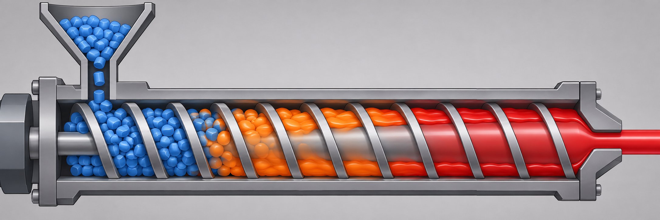
A single extruder screw may look like one continuous helix, but it functions as three distinct machines bolted end to end. Each zone has a specific job, a specific geometry, and a specific failure mode when that geometry is wrong. The parameters discussed in the previous section—channel depth, compression ratio, flight width—don't carry equal weight everywhere along the screw. Their importance shifts dramatically depending on which zone you're examining. Understanding that shift is what separates a screw that merely turns from one that consistently delivers defect-free melt.
Here are the three functional zones in the order a polymer pellet encounters them:
- Feed zone – Accepts solid pellets from the hopper and conveys them forward as a compacted bed.
- Compression (transition) zone – Tapers the channel depth to compact the solids, expel trapped air, and drive the melting process.
- Metering zone – Maintains a shallow, constant-depth channel to homogenize melt temperature and deliver steady, pulsation-free output to the die.
Each zone's geometry directly determines whether the next zone receives material in the right condition. A poorly designed feed section starves the compression zone; a mismatched compression taper delivers inconsistently melted polymer to the metering section. The entire screw extrusion process is only as strong as its weakest zone.
Feed Zone Design and Solids Conveying
The feed zone is where solid pellets first contact the screw, and its primary job is deceptively simple: grab those pellets and push them forward. The channel here is deliberately deep—the deepest anywhere on the screw—because bulk polymer pellets contain roughly 40% to 50% interstitial air by volume. A deep channel accommodates that low bulk density and maximizes the mass of material the screw can ingest per revolution.
But "grab and push" is harder than it sounds. Successful solids conveying depends on a friction differential: pellets must slip on the screw root and grip the barrel wall. If friction conditions reverse—pellets stick to the screw and slide along the barrel—forward conveyance stalls. This is why the barrel surface finish in the feed section and the screw root surface both matter. Chrome-plating a screw root, for instance, can increase slip on the root, which improves conveying, while the barrel surface is left rougher to maximize grip on the solid bed.
Upstream of the screw itself, two geometry details that many practitioners overlook heavily influence feed performance: the feed throat and the hopper design. The feed throat is the opening in the barrel through which pellets drop onto the screw. Research has shown that a decreasing feed opening width reduces specific throughput, while increasing feed opening length raises it. Shape matters too—circular openings tend to outperform square or parallelogram geometries of the same area, largely because a circle provides the greatest axial length for a given cross section. Even hopper geometry influences how consistently pellets flow into the throat, particularly with regrind or irregularly shaped feedstock that bridges or rat-holes.
Grooved vs. Smooth Barrel Feed Sections
One of the most consequential design choices for any plastic single screw extruder is whether the feed section barrel bore is smooth or grooved. In a smooth bore, pressure builds gradually along the entire screw length. The extruder output is sensitive to die backpressure—increase restriction at the die, and throughput drops because the entire conveying chain relies on friction that can be overwhelmed by downstream resistance.
Grooved feed sections change this dynamic fundamentally. Axial or helical grooves machined into a water-cooled feed barrel lock the solid bed against the barrel wall, preventing pellets from spinning with the screw. The result is dramatically higher conveying pressure generated right in the feed zone itself. As experimental investigations at the University of Stuttgart confirmed, grooved barrel extruders develop their significant pressure buildup in the feed zone, and the subsequent melting and metering zones act as pressure consumers rather than pressure builders. A practical consequence: throughput in grooved-feed systems becomes largely independent of die backpressure, giving operators much tighter control over output stability.
There is a trade-off, however. Grooved feed systems require a dedicated water-cooling jacket around the feed section to prevent premature pellet melting, and the screw geometry must adapt—typically with a shallower feed zone and deeper metering zone, sometimes with no compression at all. Because a deep metering channel offers poor inherent mixing, grooved-feed screws frequently incorporate an intensive mixing section or a static mixer downstream to compensate. Granule shape and size also interact with groove geometry: small, spherical granules maintain linear throughput to much higher screw speeds than larger lenticular or cylindrical pellets, which begin to exhibit throughput fall-off at lower speeds due to vortex formation at the feed opening.
Compression Zone Taper and Melting Mechanics
Once the solid bed advances past the feed zone, it enters the compression—or transition—zone, where the channel depth gradually decreases. Imagine the walls slowly closing in on a mass of softening polymer: that's essentially what happens. The shrinking channel compacts the solids against the heated barrel wall, squeezes out trapped air (which must escape backward toward the hopper, not forward into the melt), and generates the hydrostatic pressure necessary to sustain the melting process.
The rate at which channel depth decreases—the taper angle or taper gradient—is one of the most sensitive geometry decisions in plastic extruder screw design. A steep taper melts aggressively, building pressure quickly and completing the solid-to-melt transition over fewer screw turns. That can be ideal for high-throughput polyolefin lines where the polymer tolerates moderate shear. A gradual taper, by contrast, spreads the melting work over a longer section, generating less localized shear stress—essential for thermally sensitive resins like PVC that degrade under excessive mechanical energy input.
Here's the critical link back to the parameters table from the previous section: the compression ratio is literally defined by the channel-depth relationship between the feed zone and the metering zone, and the compression zone is where that depth change physically occurs. A 3.5:1 compression ratio on a screw with a 10.5 mm feed depth and a 3.0 mm metering depth means the taper must remove 7.5 mm of channel depth across the length of the compression zone. Spread that reduction over four turns and you get an aggressive taper; spread it over eight turns and you get a gentle one. The number of turns allocated to the compression zone, then, directly controls how fast or slow the pressure ramp is—and by extension, how stable the melting front remains.
An unstable melting front is one of the most common root causes of output surging. If the taper is too aggressive for the polymer's melting rate, solid pellets can break through the melt film and enter the metering zone unmelted—creating pressure fluctuations that propagate all the way to the die lip as visible pulsation in the extrudate.
Metering Zone Depth and Output Stability
By the time polymer reaches the metering zone, it should be fully melted. The metering section's job is to take that melt, homogenize its temperature profile, and deliver it to the die at a constant volumetric flow rate. Its channel depth is constant and shallow—much shallower than the feed zone—because a thin melt layer is easier to bring to a uniform temperature than a thick one.
The metering zone is the primary pumping section of the screw. Output here is governed by drag flow—the forward movement of melt caused by the rotating screw—minus pressure flow, the backward leakage driven by the die's resistance. A deeper metering channel increases drag flow (more volume per revolution) but weakens pressure capability, meaning the screw struggles to push melt through restrictive dies. A shallower channel generates higher pressure but at lower throughput and higher shear rates, which can raise melt temperature beyond the target window.
For most general-purpose applications, the metering zone occupies roughly 20% to 30% of total screw length, though this ratio isn't fixed. Semi-crystalline polymers like PE and PP, which release their latent heat of fusion over a relatively narrow temperature range, often benefit from a longer metering zone that ensures complete thermal homogenization. Amorphous polymers like PS, which soften gradually over a broad temperature range, may need less metering length but more compression length to complete the glass-transition-driven softening. PVC screws often feature extended metering zones at very moderate depths to limit shear heating while still achieving the output consistency rigid profiles demand.
The interplay between zone lengths is where the art of screw extrusion design meets the science. A common general-purpose split is roughly 50% feed, 25% compression, and 25% metering—but polymer rheology routinely shifts those proportions. High-viscosity resins may need a longer compression zone to complete melting. Vented (two-stage) screws, used for moisture-sensitive polymers like PET and nylon, effectively double the zonal architecture: a complete three-zone first stage melts the polymer, a sudden depth increase decompresses the melt under vacuum to remove volatiles, and a second-stage metering section repressurizes the melt for the die.
What ties all three zones together is a single throughline: each zone must hand off material to the next in the correct state—solid and compacted from the feed zone, mostly melted from the compression zone, and fully homogenized from the metering zone. When that handoff fails, defects follow. But the specific nature of those defects—and the screw dimensions responsible—depends heavily on which polymer family is running. Different resins demand fundamentally different zone geometries, a reality that makes polymer-specific screw selection one of the most impactful decisions in the entire extrusion workflow.
Matching Screw Geometry to Polymer Properties
A screw design that performs brilliantly with HDPE can thermally destroy PVC in a matter of minutes. That's not hyperbole—it's the direct consequence of polymer rheology governing every geometry decision an engineer makes. Melt viscosity, thermal conductivity, melting point range, and degradation sensitivity all differ wildly across polymer families, and those differences demand fundamentally different channel depths, compression profiles, and L/D selections. Yet many processors still run a "general-purpose" screw across multiple resins, wondering why defects appear every time the material changes.
The sections below map the most common polymer families to their recommended screw geometry parameters, giving you a structured reference for every single screw extrusion machine on your floor.
Polyolefin Screw Design Considerations
Polyethylene and polypropylene dominate global extrusion volumes, but the two polyolefins—and even sub-grades within each—don't respond identically to the same screw profile.
HDPE is a semi-crystalline polymer with a sharp, well-defined melting point and relatively high melt viscosity. It tolerates—and often requires—aggressive compaction to complete the solid-to-melt transition efficiently. Compression ratios in the 3:1 to 3.5:1 range work well for HDPE pipe, blow molding, and sheet applications, paired with L/D ratios of 24:1 to 30:1 depending on mixing demands. Barrier screw designs are especially effective for high-output HDPE lines because they separate the solid bed from the melt pool, preventing unmelted pellets from slipping into the metering zone.
LDPE, by contrast, has a broader melting range and lower melt viscosity. It's more sensitive to excessive shear, which can overheat the thin-gauge melt common in film applications. Gentler extrusion screw compression ratios of 2.5:1 to 3:1 help avoid temperature overshoot, and L/D ratios of 24:1 to 30:1 provide sufficient melting length without unnecessary residence time.
PP shares polyethylene's semi-crystalline nature but is particularly vulnerable to beta-scission—a degradation mechanism where polymer chains break at tertiary carbon sites, rapidly dropping molecular weight and spiking the melt flow index. Screw design for PP should prioritize moderate compression (2.5:1 to 3.5:1), low shear intensity, and barrel temperatures at the lower end of the 190-260°C processing window to slow oxidative reactions.
PVC and Thermally Sensitive Polymer Profiles
PVC stands apart from every other commodity resin in extrusion. Its thermal processing window is dangerously narrow—material that hasn't reached approximately 180-200°C won't gel properly, but material pushed even slightly higher begins releasing hydrochloric acid and degrading irreversibly. As polymer engineering specialists note, the ideal processing of rigid PVC involves heating the material very evenly to about 150°C with all additives consistently distributed, then shearing and heating to a final temperature of 180-200°C for optimal gelling.
This thermal sensitivity dictates every screw geometry choice. Low compression ratios—typically 2.0:1 to 2.5:1—limit mechanical shear heat generation. L/D ratios of 20:1 to 25:1 keep residence time short, reducing the window for thermal degradation. Metering-zone channel depths are kept relatively generous compared to polyolefin screws, again to limit shear rates. Flight clearances must remain tight to prevent melt recirculation and localized overheating—but the screw must also avoid aggressive compression that creates sudden pressure spikes, which cause melt turbulence and accelerate screw wear.
PS (polystyrene) is another thermally sensitive amorphous resin, though for different reasons. It softens gradually across a wide temperature range rather than melting at a sharp point. Excessive shear generates styrene monomer—a safety and quality concern. PS screws typically use compression ratios of 2.5:1 to 3:1 with smooth-bore feed sections, moderate metering depths, and L/D ratios of 24:1 to 28:1.
Engineering Resins and High-Performance Polymers
PET presents one of the most demanding screw design challenges. This hygroscopic polyester must be processed below 0.02% moisture content to avoid hydrolytic degradation—a threshold so tight that even properly dried PET can reabsorb enough atmospheric moisture to exceed it within minutes. Vented (two-stage) screw designs are strongly recommended, with a decompression section positioned along the barrel where vacuum ports extract residual moisture and volatiles. PET screws are often specified around 28:1 to 32:1 L/D in sheet operations, with the vent section consuming several diameters of screw length. Compression ratios of 3:1 to 3.25:1 must be paired with barrier flights and distributive—not dispersive—mixing elements to avoid excessive shear that accelerates chain scission in an already moisture-sensitive melt.
Nylon (PA) shares PET's moisture sensitivity but adds the complication of a very high melting point (approximately 220-260°C depending on grade) and a tendency to oxidize at processing temperatures. Vented barrels are essential for PA extrusion. Compression ratios of 3:1 to 3.5:1 suit most PA grades, and L/D ratios of 24:1 to 30:1 are typical. The screw must achieve complete melting quickly to minimize the time PA spends at peak temperature, and mixing sections should be positioned to homogenize temperature without extending residence time.
| Polymer Family | Compression Ratio Range | Preferred L/D Range | Special Design Notes |
|---|---|---|---|
| HDPE | 3:1 – 3.5:1 | 24:1 – 30:1 | Barrier flights recommended for high-output lines; tolerates moderate shear; grooved feed effective for flake or regrind |
| LDPE | 2.5:1 – 3:1 | 24:1 – 30:1 | Gentle compression to avoid overheating thin-gauge film melt; avoid aggressive metering depths |
| PP | 2.5:1 – 3.5:1 | 24:1 – 30:1 | Low shear critical to prevent beta-scission; shorter metering zone reduces residence time; moderate barrel temperatures |
| PVC | 2.0:1 – 2.5:1 | 20:1 – 25:1 | Narrow thermal window demands low compression and short residence time; avoid sudden pressure spikes; corrosion-resistant metallurgy essential |
| PS | 2.5:1 – 3:1 | 24:1 – 28:1 | Amorphous—softens gradually; excessive shear generates styrene monomer; smooth-bore feed often preferred |
| PET | 3:1 – 3.25:1 | 28:1 – 32:1 | Vented two-stage screw strongly recommended; barrier flights improve melt uniformity; minimize dead volume and residence time |
| Nylon (PA) | 3:1 – 3.5:1 | 24:1 – 30:1 | Vented barrel required; high melt temperature increases oxidation risk; fast melting with short high-temperature exposure preferred |
One increasingly important variable doesn't appear in the table above: feedstock history. Processing recycled and bio-based polymers introduces contamination, inconsistent bulk density, and variable melt flow indices that shift optimal screw geometry away from textbook virgin-resin values. A recycled HDPE bottle flake, for example, has already endured at least one high-shear processing cycle—its molecular weight is lower, its melt flow rate higher, and its tolerance for additional shear reduced. Bio-based resins may exhibit different crystallization behavior or contain residual additives that alter friction in the feed zone. These realities increasingly demand application-specific engineering rather than catalog selection.
For teams ready to translate these polymer-specific principles into an actual screw build, the gap between knowing the right compression ratio and specifying a complete screw profile can be significant. Services like NANHAIYA's custom screw design offer a practical path forward—their engineers review flight depths, compression ratios, mixing sections, materials, and surface treatments against the specific polymer behavior, machine dimensions, temperature limits, and production targets of each application before moving to manufacturing. That kind of application-level review is especially valuable when processing thermally sensitive resins like PVC or moisture-critical polymers like PET, where small geometry errors carry outsized consequences.
Selecting the right compression ratio and zone proportions for a given polymer, however, only addresses the conventional three-zone screw. Many modern applications demand performance that a standard geometry simply cannot deliver—higher melting efficiency, tighter melt-temperature uniformity, or better mixing without adding shear. That's exactly where barrier screws, specialized mixing elements, and advanced screw innovations enter the picture.
Barrier Screws and Mixing Section Innovations
A standard three-zone screw handles a wide range of applications competently—but competently isn't the same as optimally. When throughput targets climb, melt-temperature tolerances tighten, or polymer properties make conventional melting unreliable, engineers turn to advanced screw geometries that attack specific performance bottlenecks. Barrier flights, specialized mixing elements, and wave-type channel designs represent decades of innovation layered on top of the classic feed-compression-metering architecture. Understanding how each works—and where each fits—gives you the vocabulary to specify a screw that doesn't just process polymer, but processes it precisely.
Barrier Flight Screws and Melting Efficiency
The fundamental limitation of a conventional single-flight screw is that solids and melt share the same channel. As the solid bed melts against the barrel wall, the growing melt pool pushes the remaining solids aside. If anything disrupts the solid bed—thermal irregularity, a hard pellet cluster, a momentary drop in back pressure—unmelted fragments can break loose and slip into the metering zone. The result is temperature variation, pressure pulsation, and visible defects in the extrudate.
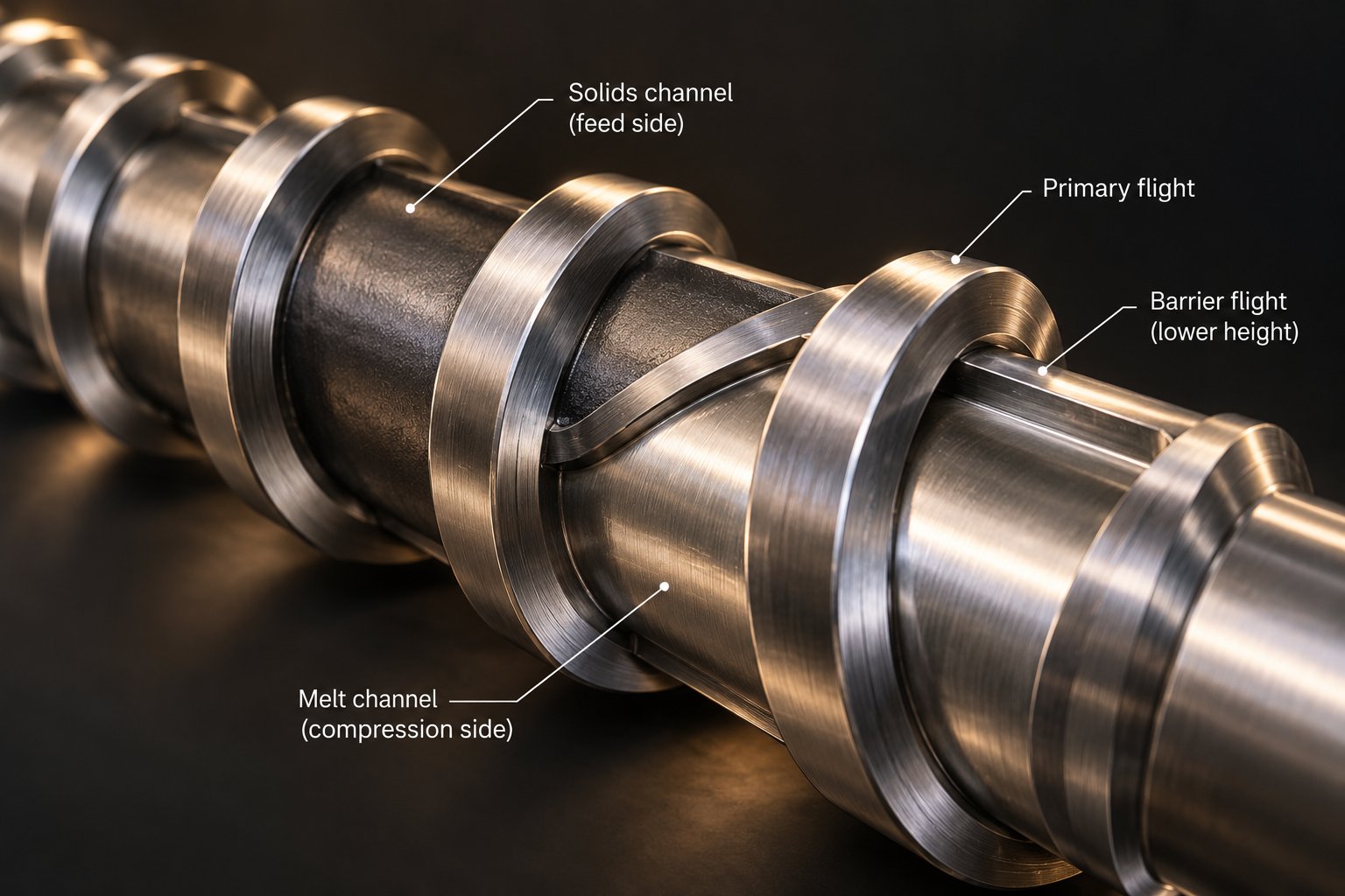
A barrier screw design for an extruder solves this problem with an elegantly simple addition: a secondary flight, slightly undercut from the barrel wall, that physically separates the solids channel from the melt channel. As the polymer melts along the barrel surface, the melt film passes over the barrier flight into the dedicated melt channel, while solid fragments remain trapped in the narrowing solids channel. This separation forces melting to completion before material enters the metering zone—dramatically improving thermal homogeneity and reducing output surging.
Two principal barrier screw types dominate the industry. The crossing (Maillefer) type was one of the earliest designs, using a barrier flight that gradually crosses over the main flight path so the solids channel narrows while the melt channel widens. The parallel (Barr) type, introduced later, keeps the barrier flight roughly parallel to the main flight. Both remain widely used, often with modifications that combine features of each—but they are not interchangeable. The design choice depends primarily on the melting requirements of the polymer.
For polymers with higher energy requirements—those with high melting points, high specific heats, or strong shear-thinning behavior—parallel barrier designs generally perform better. On a 3.5-inch screw with standard pitch and 10 diameters of barrier flight, the parallel design typically provides approximately one-third more solids-channel surface area than an equivalent crossing type. Since melting capacity is largely proportional to surface area available for solid-melt contact, that extra area translates directly into higher output with good melt quality for demanding resins like HDPE.
Crossing barriers, conversely, suit polymers with lower energy requirements—low processing temperatures, low specific heats, or minimal shear thinning. They also offer a practical advantage for hard or slippery polymers: the crossing geometry introduces no sudden restriction at the barrier start, so the solid bed doesn't need to abruptly reshape itself. Hard, brittle solid beds that would fracture at a sudden channel-width change remain stable in a crossing barrier, reducing output instability and air-entrapment issues.
One critical detail at the end of the barrier section: the solids channel exit can be either closed or open. A closed exit demands that nearly all melting finishes before the solids channel terminates—otherwise, the channel plugs with solids, causing pressure fluctuations and accelerated screw wear. An open exit lets residual solids pass through but requires downstream mixing to complete homogenization. Either approach demands careful engineering calculations to size the barrier section correctly and provide a wide processing window.
Dispersive and Distributive Mixing Elements
Even with a well-designed barrier section, the melt arriving at the end of the screw may not be homogeneous enough for every application. Color concentrates may not be uniformly distributed. Temperature gradients can persist between the barrel-side and screw-root-side melt layers. Additive agglomerates may survive the melting process intact. That's where dedicated mixing elements come in—optional downstream sections added to the metering zone or placed between the barrier section and the die.
Mixing in any extruder breaks down into two fundamentally different mechanisms. Dispersive mixing breaks agglomerates, gels, or unmelted fragments into finer particles by subjecting them to high stress—primarily shear and elongational forces—across narrow gaps. Distributive mixing rearranges and redistributes material streams throughout the melt cross-section without necessarily applying high stress, using repeated splitting, reorientation, and recombination of flow paths. Good melt quality demands both: dispersive action to eliminate discrete inhomogeneities, and distributive action to ensure uniform composition across the entire flow channel.
Here are the most common extruder mixing element types, grouped by their primary function:
- Maddock (Union Carbide) mixer – A dispersive design featuring alternating fluted channels separated by lands. Melt enters inlet channels, is forced over a narrow clearance gap at the barrier land, and exits through adjacent outlet channels. The tight gap subjects every polymer stream to high shear, breaking up gels and unmelts. Maddock mixer screw extrusion is one of the most widely adopted mixing solutions for single-screw systems due to its simplicity and effectiveness.
- Blister ring – A simple dispersive element consisting of a cylindrical restriction with a tight clearance to the barrel wall. All melt must pass through the narrow annular gap, ensuring uniform shear exposure. Less aggressive than a Maddock mixer, it's often used as a melt seal or secondary shear point.
- Pin mixing section – A distributive design where rows of pins protrude from the screw root into the flow channel, repeatedly splitting and recombining melt streams. Because pins don't create narrow gaps, shear stress stays low—making this design ideal for thermally sensitive polymers where temperature uniformity matters more than agglomerate breakup.
- Saxton mixer – A distributive element with multiple secondary flights at varying helix angles that create cross-channel flow. Melt is continually redirected, promoting thorough rearrangement of flow layers without the high shear of dispersive designs.
- Cavity transfer mixer (CTM) – A specialized distributive design with hemispherical cavities machined into both the screw and barrel surfaces. As the screw rotates, melt transfers between stator and rotor cavities in a complex three-dimensional pattern, producing exceptionally thorough distributive mixing with minimal shear-induced temperature rise.
In practice, many screw builds combine a dispersive element followed by a distributive one. A Maddock mixer might break up residual gels, while a downstream pin section redistributes the now-uniform melt. The specific combination—and whether any mixing element is needed at all—depends entirely on the application. A pipe extrusion line running pre-compounded HDPE may need nothing more than a barrier screw with a standard metering zone. A color-critical film line, on the other hand, might demand a Maddock-plus-Saxton combination to eliminate both unmelted specks and color streaks.
Wave Screws, Grooved Feed Sections, and Emerging Designs
Barrier screws and bolt-on mixing elements aren't the only paths to better performance. Wave screw extruder design takes a fundamentally different approach to melting and mixing by reshaping the channel-depth profile itself.
A wave screw replaces the constant-depth metering section (and sometimes the barrier section entirely) with a channel whose depth oscillates in a wave-like pattern. The goal: break up the solid bed as early as possible by repeatedly compressing and expanding it, distributing solid fragments throughout the surrounding melt rather than keeping them confined in a single bed. This mechanism—called disperse melting—contrasts with the conventional contiguous-bed melting of standard screws and allows a higher melting rate and a lower melt temperature to be achieved simultaneously.
The two most widespread wave concepts are the double-wave screw and the energy-transfer (ET) screw. Both use two-flighted geometries with out-of-phase waves—a crest in one channel aligns with a trough in the adjacent channel, forcing melt to flow back and forth across the secondary flight. The double-wave design uses a distinct main flight and a secondary barrier-like flight, while the ET screw eliminates the distinction between main and secondary flights, alternately setting them down so that material flows upstream against the conveying direction before being redirected. This produces an even more complex flow pattern and further improved mixing.
Research at the University of Paderborn compared ET screws against barrier screws and conventional five-section screws on a 45 mm extruder using both PP and HDPE at 75 kg/h. The results were striking: ET screws achieved significantly better thermal and material homogeneity than barrier screws for both polymers. For HDPE in particular, thin-section analysis showed a reasonably homogeneous color distribution with ET screws, while barrier and five-section screws left unmixed white areas at the flow-channel edges. The study concluded that the superior mixing of ET screws can either raise product quality at the same throughput—or increase throughput at equivalent quality, boosting economic efficiency.
Grooved feed sections, discussed briefly in the zone-by-zone section, deserve mention here as another innovation that changes how the entire screw profile is designed. By generating high conveying pressure at the feed end, grooved barrels decouple throughput from die backpressure and enable deeper metering channels without sacrificing output stability. However, that deeper metering channel reduces shear mixing, so grooved-feed systems almost always require a dedicated mixing section downstream—making advanced mixing elements not optional extras, but essential complements.
Computational simulation is increasingly accessible as a tool for evaluating all of these advanced geometries before cutting metal. Finite-element and computational fluid dynamics (CFD) models can predict melt-temperature distributions, shear-rate fields, pressure profiles, and residence-time distributions for candidate screw designs—helping engineers compare a barrier screw against a wave screw, or evaluate whether adding a Maddock mixer section will solve a homogeneity problem, without the cost and lead time of physical prototyping. While simulation doesn't replace empirical validation, it dramatically narrows the field of viable designs and reduces the risk of expensive trial-and-error on the production floor.
These advanced geometries—barrier flights, mixing elements, wave designs—all improve what happens inside the barrel. But no screw operates in isolation. Its output and melt quality ultimately depend on how its pumping characteristics interact with the resistance of the die sitting at the end of the line—a relationship that also governs how confidently a proven screw design can be scaled from a pilot extruder to a full-production machine.
Single Screw vs Twin Screw Extruder: A Decision Guide
Every barrier flight, wave channel, and Maddock mixer discussed so far aims to push single screw performance closer to its theoretical ceiling. Yet a question lingers in almost every extrusion engineering meeting: would a twin screw extruder simply solve the problem instead? The answer isn't as straightforward as marketing literature on either side suggests. Choosing between a single screw vs twin screw extruder isn't about picking a winner—it's about matching machine architecture to application requirements. The wrong choice wastes capital. The right choice compounds returns for the life of the line.
Where Single Screw Extruders Outperform Twin Screw
If your process involves melting a pre-compounded resin and pushing it through a die at high, steady-state output—think pipe, profile, sheet, or blown film—a single screw extruder is almost always the more efficient tool. Why? Several converging advantages make it the dominant architecture for these applications:
- Capital cost – A single screw system typically costs 30% to 50% less than a comparable-diameter twin screw line. Simpler barrel construction, a single-element screw, and a less complex gearbox all drive the price gap. For processors running a known resin on a proven product, that savings flows straight to the bottom line.
- Maintenance simplicity – One screw, one barrel bore, one set of wear surfaces. Downtime for screw pulls, inspections, and replacements is shorter, and spare-parts inventory is leaner. Single screw extruders are simple to maintain and use, a practical advantage that compounds over years of production.
- Throughput consistency – In steady-state operation on a well-matched resin, single screw systems deliver remarkably stable output. The drag-flow pumping mechanism is inherently smooth when the metering zone is properly sized, and advanced barrier or wave screw designs further reduce pulsation. For products where dimensional tolerance is critical—rigid PVC window profiles, for example—this stability is a core requirement, not a bonus.
- Energy efficiency per kilogram – Single screw extruders convert a high percentage of motor energy into useful melt conveying because the drag-flow mechanism is thermodynamically efficient for simple forward pumping. Twin screw machines, with their intermeshing geometry and more complex flow patterns, often consume more specific energy (kWh per kg) for equivalent throughput of a pre-compounded resin.
- Scale-up simplicity – Going from a 60 mm pilot screw to a 150 mm production screw follows well-understood geometric scaling rules. Twin screw scale-up involves additional complications around torque density, intermesh geometry, and modular screw element interactions that make the jump from lab to production more iterative.
The key qualifier in each of those advantages is pre-compounded resin. When the polymer arrives at the hopper already blended, pigmented, and stabilized—ready to melt and shape—the single screw extruder's straightforward drag-flow pumping is all you need. The mixing demands are moderate, the conveying requirements are predictable, and the simpler machine wins on economics.
When Twin Screw Architecture Is Necessary
Imagine instead that raw polymer pellets must be blended with 40% calcium carbonate filler, a color concentrate, and a stabilizer package—all inside the extruder itself. Or picture a reactive extrusion process where two chemical species must be intimately mixed and reacted under controlled residence time. These scenarios change the calculus entirely, and twin screw extruders become the clear choice.
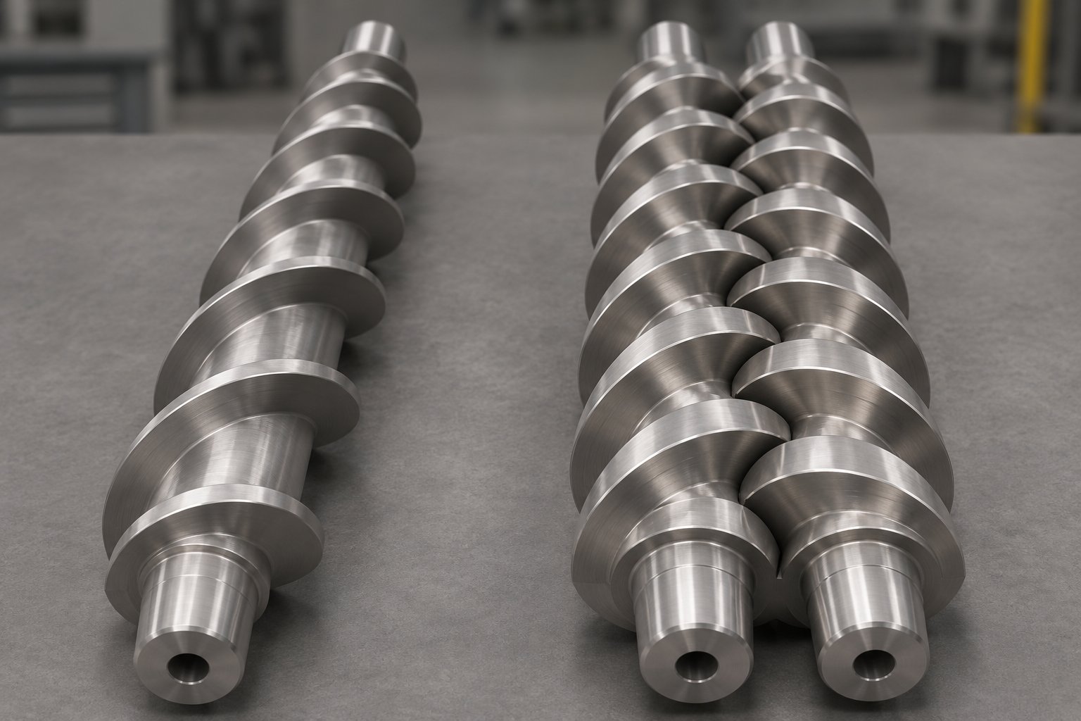
The fundamental difference is the intermeshing, self-wiping screw geometry. Twin screw extruders offer better mixing, venting, and self-cleaning capabilities than any single screw system, regardless of how many mixing sections you bolt on. Co-rotating intermeshing twin screws use modular screw elements—conveying segments, kneading blocks, reverse elements, toothed mixers—that can be reconfigured on the shaft to tailor the shear, mixing intensity, and residence time to each specific formulation. You'll find twin screw extruder advantages most pronounced in these situations:
- Compounding – Dispersing fillers, reinforcing fibers, or blending immiscible polymer pairs requires both high dispersive shear and thorough distributive mixing. Kneading blocks in a twin screw achieve both simultaneously, making the architecture the industry standard for masterbatch, glass-fiber-reinforced nylon, and HFFR cable compounds.
- Reactive extrusion – Grafting, crosslinking, or polymerization reactions inside the barrel demand narrow residence time distribution so every polymer chain spends nearly the same time at reaction temperature. Twin screws deliver a much tighter residence time distribution than single screws, where a broad range of flow paths means some melt lingers far longer than average.
- Devolatilization – Removing solvents, moisture, or reaction byproducts is more effective in a twin screw because the self-wiping action continuously renews the melt surface exposed to vacuum ports. Single screw vented designs work, but their devolatilization efficiency is lower per unit of barrel length.
- Powder and irregular feedstocks – Twin screws have good feeding characteristics, especially for powder materials. The positive-displacement conveying of intermeshing screws pulls in low-bulk-density feeds that would bridge or starve a single screw hopper.
A single screw extruder for compounding isn't impossible—low-additive-loading blends with easy-to-disperse colorants can sometimes be handled by a single screw equipped with aggressive mixing elements. But for anything beyond light-duty blending, the twin screw's modular mixing capability and self-wiping geometry are difficult to replicate.
Bridging the Gap with Advanced Single Screw Designs
Here's where the misconception that twin screw is always superior breaks down. For a large share of the extrusion market—film, sheet, pipe, profiles, and coatings—the polymer is already compounded before it reaches the extruder. The processing challenge isn't intensive mixing; it's efficient melting, thermal uniformity, and stable pumping. And in that arena, a modern single screw extruder equipped with barrier flights, a Maddock mixer, and perhaps a wave-type metering section can match or exceed the melt quality of a twin screw at significantly lower cost and complexity.
Consider a blown-film line running pigmented LDPE. A twin screw could certainly melt and mix the material—but at roughly double the capital cost, higher maintenance burden, and no meaningful quality advantage over a well-designed barrier screw with a distributive mixing section. The economics simply don't justify the upgrade. Industry data consistently confirms this: single screw extruders remain the dominant architecture worldwide for high-volume, steady-state converting operations, precisely because advanced screw geometries have closed the mixing gap for most shaping applications.
The real decision framework, then, isn't "which is better?" but "what does the application demand?" Use this extruder type selection guide as a starting point:
| Criterion | Single Screw Extruder | Twin Screw Extruder |
|---|---|---|
| Capital Cost | Lower (30-50% less for comparable diameter) | Higher; complex gearbox, segmented barrel and screw elements |
| Mixing Quality | Moderate; improved significantly with barrier flights and mixing elements | Excellent; modular kneading blocks deliver high dispersive and distributive mixing |
| Throughput Consistency | Very high in steady-state operation on pre-compounded resin | High; starve-fed operation decouples feed rate from screw speed |
| Maintenance Complexity | Low; single screw pull, simpler wear surfaces | Higher; segmented screws, split barrels, more wear points |
| Shear Control | Limited to screw geometry and speed; less independent adjustment | Highly adjustable via screw element selection, speed, and feed rate independently |
| Feed Versatility | Best with pellets; powders and irregular feeds may require grooved feed sections | Handles pellets, powders, fibers, liquids, and starve-fed streams easily |
| Residence Time Distribution | Broader; some melt stays longer than average due to channel flow patterns | Narrower; self-wiping action reduces dead zones and stagnation |
| Self-Wiping Capability | None; material can stagnate in dead spots if screw geometry isn't optimized | Inherent in co-rotating intermeshing designs; reduces degradation risk |
| Scale-Up Simplicity | Straightforward geometric scaling rules; well-established correlations | More complex; torque density and modular element interactions add variables |
| Typical Applications | Pipe, profile, sheet, blown film, wire coating, foam extrusion | Compounding, masterbatch, reactive extrusion, devolatilization, direct sheet extrusion |
Notice that many rows in the table show a spectrum, not a binary advantage. A single screw with a Maddock mixer and barrier flights pushes its mixing-quality rating significantly closer to a twin screw. A twin screw running a simple, pre-compounded resin offers no practical benefit over a single screw that costs half as much. The decision hinges on where your application sits along these spectra—and on honest assessment of whether the mixing, feeding, or devolatilization demands of your process genuinely require the added complexity.
What the table can't capture, however, is the dynamic interaction between the screw and the rest of the extrusion system. Regardless of whether you choose one screw or two, the extruder's actual output and melt quality settle at the point where screw pumping capability meets die resistance—a relationship governed by pressure-flow curves that shift every time screw geometry changes. Understanding that operating-point concept, and knowing how to preserve it when scaling from a pilot machine to full production, is essential knowledge for anyone specifying either architecture.
Screw-Die Interaction and Scale-Up Principles
Every screw geometry parameter discussed so far—channel depth, compression ratio, barrier flights, mixing elements—ultimately feeds into a single question on the production floor: how much melt, at what pressure, actually reaches the die? The answer doesn't live in the screw alone. It emerges from the dynamic interplay between the screw's pumping capability and the die's flow resistance. Ignore that relationship during design, and even a textbook-perfect screw will underperform. The same principle governs what happens when you try to replicate a successful pilot-scale screw on a larger production machine—a process that trips up experienced engineers more often than anyone likes to admit.
The Screw-Die Operating Point Concept
Imagine plotting two curves on the same graph. On the vertical axis is output (kg/h); on the horizontal axis is head pressure (the pressure at the screw tip, just upstream of the die). The first curve—the extruder screw characteristic curve—slopes downward from left to right. At zero head pressure, the screw delivers its maximum drag flow: all the melt the rotating channel can push forward with no resistance. As head pressure increases, pressure-driven backflow through the channel opposes the forward drag flow, so net output decreases. The steepness of this slope depends on metering-zone channel depth, flight clearance, and melt viscosity.
The second curve—the die characteristic—slopes upward. A die is essentially a restriction: the more melt you force through it per unit time, the higher the pressure drop required. For most polymer melts at processing temperatures, this relationship is approximately linear at moderate flow rates, though shear-thinning behavior bends the curve at higher outputs.
The extruder screw die operating point is where these two curves intersect. That single point defines the actual output rate and operating pressure of the system. It's not a theoretical abstraction—it's the physical reality governing every kilogram of product your line produces.
Here's why this matters for screw geometry decisions. Deepen the metering channel by even a millimeter, and the screw characteristic shifts: maximum drag flow increases (the curve starts higher on the output axis), but the slope steepens because a deeper channel offers less resistance to pressure-driven backflow. The result? At zero or low die resistance, you get more output. But against a restrictive die—a complex profile die, a fine-strand pelletizing die, or a multi-layer film die with narrow flow gaps—that deeper channel loses pumping pressure faster. The operating point may actually slide to a lower output than the original, shallower design delivered.
Conversely, a shallower metering channel reduces maximum drag flow but flattens the screw characteristic curve. Output becomes less sensitive to die pressure variations—exactly the stability that tight-tolerance profile extrusion demands. The trade-off is higher shear rates and elevated melt temperature, which may not suit thermally sensitive resins.
A screw designed without considering die resistance will not deliver the expected output or melt quality at the actual operating point.
This principle sounds obvious in isolation, yet it's routinely violated. Engineers optimize screw geometry based on drag-flow calculations or simulation results at assumed pressures, then discover that the actual die on the production line presents a completely different resistance profile. The fix isn't complicated—it's procedural. Die pressure drop should be estimated (or measured from an existing line) and included as a boundary condition from the earliest stage of screw design, not evaluated as an afterthought during commissioning. When both the screw characteristic and the die characteristic are understood together, engineers can deliberately position the operating point where output, melt temperature, and pressure stability all fall within acceptable ranges.
Scale-Up Principles and Common Pitfalls
A screw profile that produces flawless blown film on a 45 mm pilot extruder doesn't automatically work on a 120 mm production machine. Single screw extruder scale-up is one of the most underestimated challenges in extrusion engineering—partly because the geometry looks scalable at first glance, and partly because the physics underneath resist simple proportional enlargement.
The earliest formal approach came from Carley and McKelvey in 1953, who showed that output and power consumption scale with the square of the diameter ratio (D1/D2)2 when screws share the same channel depth and rpm. The squaring effect arises because channel volume—the cross-sectional area of one helical turn—grows with the square of the diameter. Double the screw diameter, and one channel turn holds four times the volume.
But here's the trap: running both screws at the same rpm means the larger screw has a much higher peripheral speed (since peripheral speed = π × D × N). Higher peripheral speed drives higher shear rates at the barrel wall, more viscous dissipation, and hotter melt. Simply copying channel depth from a small screw to a large one while maintaining rpm produces a process that looks geometrically similar but behaves thermally very differently.
Maintaining Process Equivalence Across Machine Sizes
The core difficulty is a geometric mismatch that no scaling rule can fully eliminate. As diameter increases, internal channel volume grows with roughly D3 (considering both width and depth contributions), while barrel surface area—the primary path for heat removal—grows with only D2. The ratio of cooling surface to melt volume shrinks with every step up in size. Barrel temperature settings that kept melt at 220°C on the pilot machine may allow it to climb to 235°C on the production unit simply because there's proportionally less surface to extract heat through.
Engineers have developed several extrusion process scale-up methods to manage these trade-offs. The most widely used approaches include:
- Constant shear rate at the barrel wall – Peripheral speed (not rpm) is held constant between machines. Since shear rate in the channel approximates π·D·N/h, holding peripheral speed constant while increasing diameter requires reducing rpm proportionally. This preserves the shear environment the polymer experiences but reduces throughput gains compared to holding rpm constant.
- Channel depth scaling by (D1/D2)0.5 – An early rule of thumb that increases metering depth in proportion to the square root of the diameter ratio. This partially compensates for higher shear at larger diameters by giving the melt a deeper, lower-shear channel.
- Channel depth scaling by (D1/D2)0.7 – A refinement developed by Bruce Maddock at Union Carbide, validated against extensive blown-film data on extruders up to 4.5 inches. The 0.7 exponent produces a deeper channel than the square-root rule, further reducing shear rate to counterbalance the increased flight-leakage flow, longer flight paths, larger flight clearances, and reduced barrel-cooling effectiveness that accompany larger screw diameters. C.I. Chung independently confirmed this exponent as a "balanced" basis for overall scale-up in his 2000 book Extrusion of Polymers.
The Maddock 0.7-power rule has proven remarkably practical for screws with similar L/D, lead angle, and proportional configuration. As Jim Frankland notes, a small correction for polymers with strong shear-thinning behavior becomes important when screws are to be run at vastly different peripheral speeds—because shear-thinning shifts the effective viscosity in ways that alter the drag-flow-to-pressure-flow balance.
Why does the 0.7 power work better than 0.5? Consider what changes as diameter grows. Flight clearance increases, raising leakage flow. The longer flight path per turn creates more barrel-contact surface for shear heating. The reduced surface-to-volume ratio impairs heat removal. All of these effects push melt temperature upward. The deeper channel generated by the 0.7 exponent lowers shear rate enough to offset these thermal penalties, producing melt quality and temperature profiles on the production machine that closely match the pilot results.
Even the best scaling rule, however, is a starting point—not a guarantee. A comprehensive 2006 analysis by Chris Rauwendaal in Polymer Engineering and Science identified 14 different scale-up factors spanning shear rate, melt conveying, residence time, conductive and dissipative melting capacity, solids conveying, power consumption, heat transfer, mixing, and specific energy consumption. No single scaling exponent satisfies all 14 simultaneously. The engineer's job is to decide which factors matter most for the specific application—melt temperature uniformity for optical film, throughput maximization for commodity pipe, or residence-time control for a degradation-sensitive resin—and weight the scale-up accordingly.
This reality carries a practical implication: scaling a screw design also shifts the extruder screw characteristic curve. A production screw with a deeper metering channel (per the 0.7 rule) has a different pressure-flow relationship than the pilot screw it was derived from. If the production die is also different—wider, more lands, higher restriction—the operating point on the larger machine can land in a completely different region of the performance map. Successful scale-up, then, means scaling the screw and re-evaluating the screw-die operating point together, not treating them as independent exercises.
When the operating point is right and the scale-up delivers equivalent melt quality, the production line hums. When it's wrong, the symptoms show up as the kind of defects every extrusion operator dreads—output surging, excessive melt temperature, poor homogeneity, or outright degradation. Tracing those defects back to the specific screw geometry parameters responsible is the fastest path to a permanent fix.
Solving Extrusion Defects Through Screw Design
Output surging, gels, overheated melt, degraded resin—these problems consume shift after shift of troubleshooting time. Operators adjust barrel temperatures, swap screen packs, tweak screw speed, yet the defects persist. Why? Because the root cause often isn't a process setting. It's baked into the screw geometry itself. This screw design troubleshooting guide maps the most common extrusion defects directly to the screw dimensions responsible and the directional corrections that resolve them.
Output Surging and Feed Zone Root Causes
Cyclic output variation—visible as pulsating extrudate thickness, periodic pressure swings at the die, or rhythmic weight fluctuation—is one of the most frustrating problems in extrusion. Understanding extruder output surging causes starts with recognizing that the defect almost always originates upstream of the die, often in the first two zones of the screw.
In the feed zone, a channel that's too shallow for the polymer's bulk density starves the compression section intermittently. Pellets bridge, compact unevenly, or momentarily lose traction against the barrel wall. The result is a repeating cycle of adequate feed followed by brief starvation—each cycle appearing as a surge downstream. Experimental work confirms that solid-bed breakup in the compression and metering zones can produce repeatable pressure oscillations whose frequency changes with operating conditions, representing a legitimate surge mechanism when feed, temperature, and instrumentation have been ruled out.
The compression zone is the second major culprit. When the channel-depth taper is too aggressive for the polymer's melting rate, the solid bed fractures before it fully melts. Fragments of unmelted polymer break free, tumble into the melt pool, and temporarily block the narrowing channel—creating pressure spikes that release suddenly when the blockage clears. As melt-quality specialists note, melting that jumps forward and back along the screw produces cyclic flow at the die, weight variation, and dimensional drift. A gentler taper—spreading the same compression ratio over more screw turns—stabilizes the melt front and eliminates most compression-induced surging.
Melt Temperature, Shear, and Degradation Control
When actual melt temperature consistently exceeds the target—even with barrel setpoints dialed down—the problem is almost certainly viscous dissipation driven by screw geometry, not barrel heating. Extrusion melt temperature too high is a geometry symptom, not a heater symptom.
Three design parameters contribute most heavily:
- Metering channel depth – A channel that's too shallow forces all melt through a thin, high-shear layer. Viscous heating rises exponentially as channel depth decreases, because shear rate in the metering zone approximates pi times diameter times rpm divided by channel depth. Even a one-millimeter reduction can add 10-15 degrees Celsius to melt temperature in high-viscosity resins.
- Flight clearance – Excessively tight clearance between the flight tip and barrel wall subjects melt to extreme localized shear as it leaks over the flight. While some leakage is unavoidable, a clearance tighter than necessary generates heat without improving pumping efficiency.
- Compression ratio – An overly aggressive ratio compacts the solid bed too quickly, generating frictional and viscous heat faster than the barrel can extract it. The excess thermal energy carries forward into the metering zone, raising the final melt temperature above the processing window.
Polymer degradation follows logically from excessive temperature—but it can also occur at moderate temperatures if residence time is too long. Overly deep channels in the metering zone increase the volume of melt dwelling in the screw at any moment. Dead spots behind mixing elements, in stagnant corners of worn flight roots, or in poorly transitioned barrier sections trap melt for minutes longer than the average. For thermally sensitive resins like PVC, even modest residence-time extension triggers chain scission and discoloration. The directional fix is to reduce unnecessary channel volume and eliminate geometric dead zones that allow melt to linger.
Improving Melt Homogeneity Through Design Changes
You've achieved stable output and acceptable melt temperature, yet the extrudate still shows color streaks, temperature gradients across the cross-section, or occasional gels. The extruder poor melt homogeneity fix almost always involves one of three geometry adjustments—sometimes all three.
First, evaluate whether the metering section provides enough shear history. A metering zone that's too short or too deep doesn't generate sufficient cross-channel mixing to equalize temperature differences between the barrel-side melt (hotter, from conduction) and the screw-root-side melt (cooler, from insulation). Lengthening the metering zone or shallowing its channel increases the number of shear cycles the melt undergoes, improving thermal uniformity.
Second, consider whether mixing elements are absent or undersized. A screw without any dedicated mixing section relies entirely on the metering zone's drag-flow pattern to homogenize the melt—a pattern that, in a standard single-flight channel, creates limited distributive and dispersive mixing. Adding a Maddock-type dispersive mixer breaks up residual gels and unmelt, while a downstream distributive section—pins, Saxton flights, or a cavity transfer design—redistributes flow layers for uniform composition.
Third, check whether a barrier section would prevent the problem at its source. Many homogeneity issues trace back to unmelted fragments entering the metering zone because no physical barrier separated solids from melt during the compression phase. A barrier flight forces complete melting before material reaches the metering section, eliminating the root cause rather than compensating for it downstream.
Melt fracture—the sharkskin or gross distortion visible on the extrudate surface—deserves mention here because its connection to screw geometry is often overlooked. While melt fracture is typically attributed to excessive wall shear stress at the die land, pressure pulsation from the screw amplifies the problem. Each output surge momentarily spikes die-entrance pressure, pushing wall shear stress above the critical threshold for that polymer. Stabilizing screw output through proper feed-zone depth, moderate compression taper, and adequate mixing reduces the pressure amplitude that triggers fracture at the die.
| Defect | Likely Screw Design Cause | Recommended Geometry Adjustment |
|---|---|---|
| Output surging (cyclic pressure and dimensional variation) | Feed zone too shallow for bulk density; compression taper too aggressive causing solid-bed breakup; inconsistent solids conveying from poor feed-throat match | Deepen feed channel to match pellet bulk density; lengthen compression zone to reduce taper gradient; evaluate grooved feed section for improved conveyance |
| Excessive melt temperature | Metering channel too shallow (high shear rate); flight clearance tighter than necessary; compression ratio too high for the polymer | Increase metering depth to reduce shear; verify flight clearance is within spec; lower compression ratio or extend compression zone length |
| Poor melt homogeneity (color streaks, temperature gradients, gels) | No mixing section or inadequate mixing element; metering zone too short; absence of barrier flights allowing unmelted solids to pass through | Add dispersive mixer (Maddock) for gel breakup and distributive mixer (pin or Saxton) for redistribution; lengthen metering zone; incorporate barrier flights |
| Polymer degradation (discoloration, brittleness, odor) | Excessive residence time from overly deep channels; dead spots behind mixing elements or in worn flight roots; too-high melt temperature from shear | Reduce metering channel depth to lower holdup volume; eliminate stagnant geometry; reduce compression ratio for thermally sensitive resins |
| Melt fracture (sharkskin or gross surface distortion) | Screw output pulsation amplifying die-entrance shear stress above critical threshold; unsteady metering-zone pumping | Stabilize output by correcting feed and compression zone issues listed above; add mixing section to dampen pressure variation; verify metering depth provides stable pumping against die resistance |
Every row in that table points to the same underlying truth: extrusion defects that resist process-setting adjustments are almost always geometry problems wearing a process-setting disguise. Barrel temperatures, screw speed, and screen packs can mask screw design issues temporarily—but the defects return whenever conditions shift. A permanent fix requires changing the screw dimensions that created the problem in the first place. That leads naturally to a practical question: what should the screw be made of, and how should its surfaces be treated to withstand the pressures, temperatures, and abrasive compounds that aggressive geometry corrections demand?
Extruder Screw Material Selection, Surface Treatments, and Custom Engineering
Geometry fixes only hold if the screw and barrel survive the environment they operate in. A perfectly optimized compression ratio is meaningless if the flight tips erode within months because the base metal can't handle glass-fiber-filled nylon. A shallow metering channel designed to control shear heating fails the moment worn clearances widen the gap and let melt recirculate. The materials and surface treatments you specify for the screw and barrel determine how long those carefully chosen dimensions stay within tolerance—and by extension, how long the process stays defect-free.
Screw and Barrel Material Selection Strategies
Extruder screw material selection starts with one question: what's the dominant threat your compound poses? The answer falls into three categories—abrasion, corrosion, or a combination of both—and each demands a different metallurgical response.
Nitrided alloy steel is the workhorse for general-purpose extrusion. Grades like 38CrMoAlA (a chromium-molybdenum-aluminum alloy) receive a gas nitriding treatment that diffuses nitrogen into the surface, forming a hard case typically reaching 65-72 HRC. The result is a screw with good basic wear resistance at a moderate cost—perfectly adequate for unfilled polyolefins, polystyrene, and other non-abrasive resins. Nitrided steel remains the most common starting point for both single screw and twin screw extruders processing standard compounds.
Tool steels and high-speed steels (HSS) step in when abrasion intensifies. Grades like D2 (Cr12MoV) and M2 (W6Mo5Cr4V2) contain higher concentrations of carbon, chromium, tungsten, and vanadium, achieving bulk hardness levels that nitrided alloy steels can't match. These materials suit medium-to-high-wear applications—calcium carbonate-filled compounds, talc-loaded PP, or moderately reinforced engineering resins—where flight-tip erosion would shorten a nitrided screw's service life unacceptably.
Stainless steels and nickel-based alloys address the corrosion side of the equation. PVC processing is the classic case: as rigid PVC degrades, it releases hydrochloric acid that attacks standard alloy steel from the inside out. Corrosion-resistant surfaces—whether achieved through material selection or coatings—are non-negotiable for any line running PVC, fluoropolymers, or compounds with halogenated flame retardants. Nickel-based alloys form dense passivation layers that resist acid attack, making them the preferred choice for these chemically aggressive environments.
Here's where screw geometry and material selection intersect directly. An aggressive compression ratio on an abrasive compound concentrates enormous mechanical force on the flight tips in the compression zone—exactly where the solid bed is being compacted against the barrel wall. That localized stress accelerates wear far faster than uniform processing would, meaning the same compound that runs acceptably on a 2.5:1 compression screw may destroy the flights in half the time on a 3.5:1 design. Engineers who increase compression ratio without upgrading to harder flight materials often trade a melting improvement for a maintenance crisis.
Surface Treatments and Wear-Resistant Coatings
Base material provides the foundation, but surface treatments add the protective armor. Think of them as functional upgrades applied to the screw's most vulnerable surfaces—flight tips, root surfaces, and the barrel bore—without replacing the entire component.
- Gas nitriding – The most widely used treatment for general-duty screws and barrels. The component is held in an ammonia atmosphere at 500-570°C for an extended period, diffusing nitrogen atoms into the steel surface to form an extremely hard nitride layer. Best for: unfilled or lightly filled thermoplastics where moderate nitrided screw barrel wear resistance is sufficient. Cost-effective and applicable to a broad range of alloy steels.
- Hard chrome plating – An electrochemical process that deposits a dense chromium layer onto the screw surface. Provides excellent corrosion resistance and a smooth, low-friction finish that reduces polymer adhesion. Best for: PVC and other corrosive compounds where chemical attack is the primary threat. However, adhesion limitations and susceptibility to peeling have reduced its use in high-end, high-wear applications.
- Tungsten carbide coating – A carbide layer applied to flight tips via thermal spray processes like HVOF (High Velocity Oxygen Fuel). Delivers extreme abrasion resistance precisely where wear concentrates—on the narrow flight lands that ride closest to the barrel wall. Best for: glass-fiber-reinforced compounds and mineral-filled systems where flight-tip erosion is the primary failure mode.
- Bimetallic barrel liners – A wear- and corrosion-resistant alloy (typically nickel-based or tungsten-chromium-based) metallurgically bonded to the inside of the barrel bore. Bimetallic barrel liner extrusion systems last two to three times longer than standard nitrided barrels when processing glass-fiber-reinforced or heavily filled compounds. Best for: any application combining abrasion and corrosion—calcium carbonate-filled PVC, wood-plastic composites, recycled material with metal contamination.
- Bimetallic screw construction – Similar in concept to barrel liners, a high-performance alloy is bonded to the screw's flight surfaces. Materials like Colmonoy 56, Colmonoy 83, or CPM9-V tool steel provide hardness levels that resist even the most abrasive filled systems. Best for: high-glass-fiber compounds (30%+ loading), carbon-black-filled masterbatch, and heavily mineral-filled formulations.
The practical takeaway? Material and surface treatment decisions should never be made in isolation from screw geometry. A screw with an aggressive compression profile processing a 40% CaCO3-filled compound needs harder flight materials and a bimetallic barrel liner—not one or the other. Similarly, a PVC screw with tight flight clearances (necessary to prevent melt recirculation and localized overheating) demands corrosion-resistant surfaces because any chemical erosion of the flight tips immediately widens that critical clearance gap, degrading the very geometry the design depends on.
Evaluating Application-Specific Screw Geometry with Engineering Support
If you've followed this guide from screw parameters through zone design, polymer matching, advanced geometries, scale-up principles, and defect troubleshooting, you now have the engineering vocabulary to evaluate any screw profile critically. But vocabulary and execution aren't the same thing. Translating these principles into an actual screw specification—one that balances compression ratio, barrier flight placement, mixing element selection, base material, surface treatment, and dimensional tolerances for a specific polymer on a specific machine—involves dozens of interdependent decisions that compound in complexity.
This is where custom extruder screw design service providers become a practical resource. Rather than specifying geometry by catalog or by copying a competitor's screw, engineering-driven services evaluate each variable against your actual application parameters. NANHAIYA's custom screw design service, for example, structures its engineering review around the specific polymer behavior, machine dimensions, temperature limits, and production targets of each project. Their engineers assess flight depths, compression ratios, mixing sections, material grades, and surface treatments as an integrated system—not as isolated line items on a purchase order. For processors running thermally sensitive resins like PVC, moisture-critical polymers like PET, or abrasive filled compounds that demand both geometry optimization and wear-resistant metallurgy, that application-level analysis can prevent costly trial-and-error on the production floor.
Of course, NANHAIYA isn't the only path to custom engineering. Some OEMs offer screw design consultation, and independent consultants with polymer-processing expertise can provide similar analysis. The critical point is the process, not the provider: any credible custom screw design engagement should begin with a thorough review of your resin's rheology, your machine's torque and thermal limits, your die's pressure characteristics, and your quality targets—before a single dimension is committed to a manufacturing drawing.
Whether you're correcting a defect traced to the wrong compression ratio, upgrading flight materials to handle an increasingly abrasive compound, or scaling a proven pilot screw to a production machine, the principles in this guide provide the foundation. Geometry, materials, and surface treatments aren't three separate decisions—they're one integrated engineering problem. Getting that integration right is the difference between a screw that runs for years and one that generates defects from the first shift.
Frequently Asked Questions About Single Screw Extruder Design
1. What is the most important parameter in single screw extruder design?
No single parameter stands alone—screw geometry is an interdependent system. However, the compression ratio (feed-channel depth divided by metering-channel depth) is often considered the most consequential starting point because it directly controls how aggressively the polymer is compacted and melted. Selecting the wrong compression ratio cascades into problems across all three screw zones: too high causes excessive shear heating and potential degradation, while too low results in incomplete melting and output instability. Engineers typically set the compression ratio first based on the target polymer's melt viscosity, thermal sensitivity, and crystalline structure, then tune L/D ratio, channel depths, flight width, and mixing elements around it.
2. How do I choose the right screw design for PVC extrusion?
PVC requires a uniquely conservative screw profile due to its extremely narrow thermal processing window (approximately 180-200°C). Recommended geometry includes a low compression ratio of 2.0:1 to 2.5:1 to minimize shear-generated heat, a short L/D ratio of 20:1 to 25:1 to limit residence time, and relatively generous metering-zone channel depths to keep shear rates moderate. Sudden pressure spikes from aggressive compression tapers must be avoided, as they cause melt turbulence and accelerate wear. Corrosion-resistant screw and barrel materials—such as bimetallic liners or nickel-based alloys—are non-negotiable because PVC releases hydrochloric acid during any degradation event. Services like NANHAIYA's custom screw design (nhyscrews.com) can help evaluate these geometry and metallurgy trade-offs against specific PVC formulation and machine parameters.
3. What is the difference between a barrier screw and a conventional screw in an extruder?
A conventional single-flight screw allows solids and melt to share the same channel throughout the compression zone, which means unmelted fragments can break loose and enter the metering section. A barrier screw adds a secondary flight—slightly undercut from the barrel wall—that physically separates the solids channel from the melt channel. As polymer melts against the barrel surface, the melt film passes over the barrier flight into a dedicated melt channel while solid fragments remain trapped. This separation forces complete melting before material reaches the metering zone, significantly improving thermal homogeneity and reducing output surging. Two main types exist: crossing (Maillefer) barriers suit lower-energy-requirement polymers, while parallel (Barr) barriers provide more solids-channel surface area for demanding, high-melting-point resins.
4. When should I choose a single screw extruder over a twin screw extruder?
A single screw extruder is the stronger choice when processing pre-compounded resins in steady-state shaping applications like pipe, profile, sheet, blown film, and wire coating. It offers 30-50% lower capital cost, simpler maintenance, excellent throughput consistency, and better energy efficiency per kilogram for straightforward melt-and-shape operations. Modern barrier flights and mixing elements have closed much of the historical mixing gap. Twin screw extruders become necessary when the process requires intensive compounding (dispersing high filler loads, reinforcing fibers), reactive extrusion with narrow residence-time distribution, efficient devolatilization, or feeding difficult powders and irregular feedstocks. The decision should be driven by actual application mixing, feeding, and devolatilization demands—not by the assumption that twin screw is inherently superior.
5. How do you scale up a single screw extruder design from pilot to production?
Scaling a screw design from a pilot machine (e.g., 45 mm) to a production extruder (e.g., 120 mm) requires more than proportional enlargement. The most widely validated approach uses the Maddock 0.7-power rule: metering channel depth on the larger screw scales by (D_large/D_small)^0.7. This deeper channel compensates for higher peripheral speeds, increased flight-leakage flow, longer flight paths, and the reduced surface-area-to-volume ratio that impairs heat removal on larger machines. Simply copying channel depths at the same RPM produces significantly higher melt temperatures on the production screw. Crucially, scaling the screw also shifts its pressure-flow characteristic curve, so the screw-die operating point must be re-evaluated to ensure the production system delivers equivalent output and melt quality.
Written by
Nanhaiya Technical Team
Zhoushan Nanhaiya Plastic Machinery Co., Ltd.
The Nanhaiya technical team supports screw and barrel manufacturing projects through application review, technical communication, custom manufacturing coordination, and production and quality control.
Discuss Your Application
Related Articles
More insights on screw barrel technology and plastics processing.
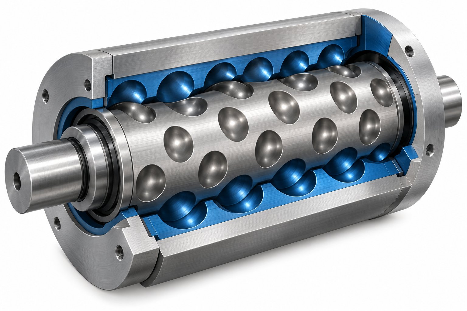
Cavity Transfer Mixer: The Blender Your Extruder Didn't Know It Needed
Nov 13, 2026
Learn how a cavity transfer mixer (CTM) upgrades single-screw extruder mixing. Covers working principles, key parameters, integration, applications, and comparisons.
Read Article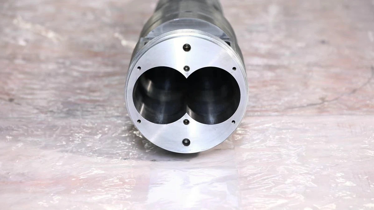
Extruder Barrel Alignment Decoded: Tolerances Most Plants Miss
Nov 13, 2026
Learn extruder barrel alignment tolerances, laser procedures, thermal offsets, and proactive schedules most plants miss — for single-screw and twin-screw lines.
Read Article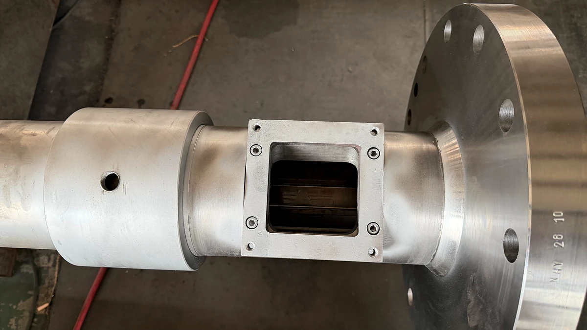
Vent Stuffer Decoded: End Vent Flow and Reclaim Lost Throughput
Nov 12, 2026
Learn what a vent stuffer is, how it prevents vent flow in twin-screw extruders, and how to size, optimize, and maintain one for peak devolatilization performance.
Read ArticleLooking for something else?
Search by material, symptom or product and jump straight to the relevant page.
These are navigation suggestions based on keyword matching — not a quotation, not a delivery commitment, and not a substitute for engineering review. Final specification is confirmed by our engineers against your drawings and processed material.
Need help with screw barrel selection?
Share your machine model, processed material and application. Our team can help with pricing and technical support.