

What Is a Vent Stuffer and How Does It Work
Imagine you are running a twin-screw extruder at high throughput. Everything looks good until you glance at the vent port and see molten polymer creeping upward, oozing out of the opening that is supposed to let moisture and gases escape. Production grinds to a halt for cleanup. Sound familiar? That scenario is called vent flow, and it is one of the most persistent headaches in compounding and devolatilization. The engineered answer is a small but powerful piece of auxiliary equipment known as a vent stuffer.
Vent Stuffer Definition and Core Function
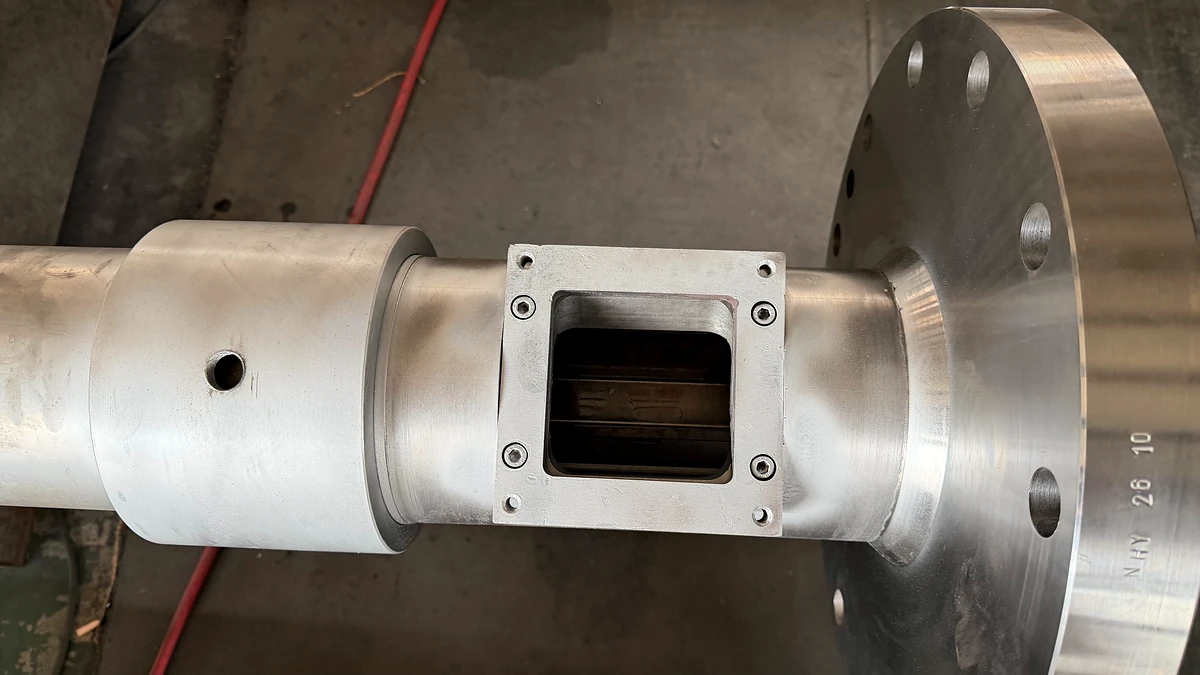
A vent stuffer is a compact, motor-driven screw device mounted directly at the vent port of a twin-screw extruder. Its screw element rotates to push escaping polymer melt back down into the barrel while keeping the vent pathway open so that volatiles — moisture, trapped air, residual monomers, and decomposition gases — can escape freely during devolatilization.
Think of it as a one-way gate for gases. Vapors rise and exit through the vent housing without obstruction, but any molten material that tries to travel upward meets the rotating screw flights and gets forced right back into the process stream. This dual action is critical because devolatilization depends on maintaining an open, unobstructed pathway between the melt surface and the vapor takeoff system. Block that pathway with escaped polymer, and volatile removal efficiency collapses.
The core problem a vent stuffer solves is straightforward. During normal extrusion, the main screws generate pressure to push material forward through the barrel and out the die. Under certain conditions — high die pressure, overfilled screw channels, or restrictive downstream mixing elements — that pressure can force melt backward and upward through any opening it finds. The vent port, designed to be an open escape route for gases, becomes an unintended exit for the compound itself. ENTEK's processing guidance describes vent flow as a situation where "polymer and/or compound flow out of a vent opening preventing air/gases from escaping out of the extruder." The result is contaminated product, wasted material, and sometimes a dangerous mess of hot polymer collecting in vent piping or on the shop floor.
A vent stuffer eliminates that chain of events by actively conveying material downward. Rather than relying on gravity or passive restrictions, it uses mechanical force — a rotating screw matched to the severity of the vent flow — to keep the vent port clear. Much like the frustration people experience when they notice stuff coming out of car vents that should not be there, processors dealing with vent flow face an unwelcome substance escaping from an opening meant only for airflow. The vent stuffer restores that intended function.
Where a Vent Stuffer Sits on the Extruder
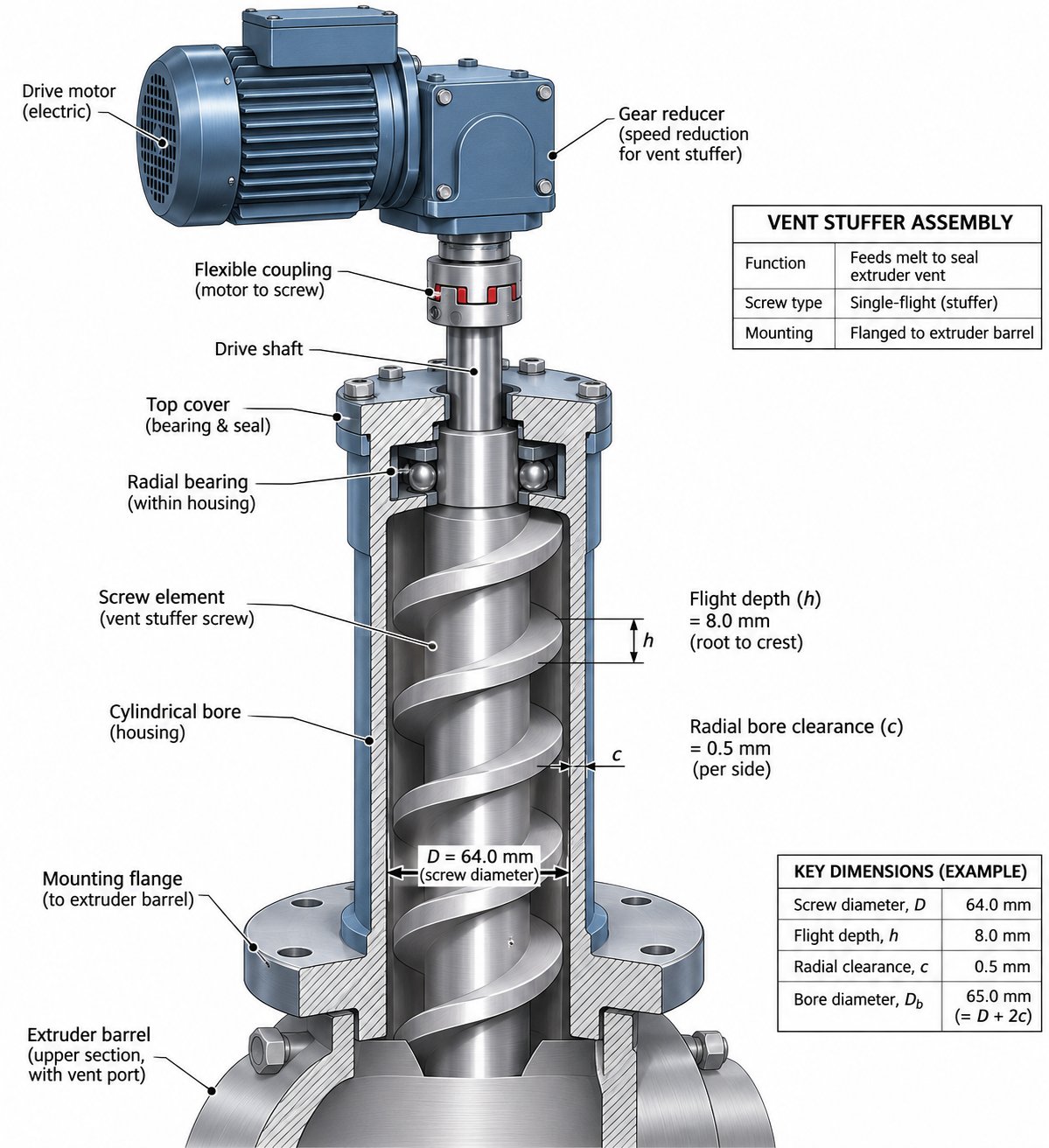
Physically, you will find a vent stuffer bolted to the barrel section that contains the vent opening. Most installations use a top-mount orientation, with the unit sitting vertically above the vent port. A compact housing encloses a short screw element — typically a single-screw design — connected to its own dedicated drive motor. The motor provides independent speed control, allowing operators to adjust conveying intensity without altering main extruder parameters.
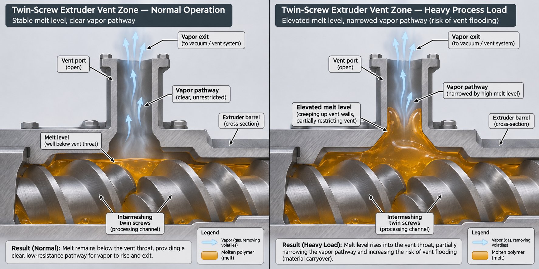
Contrast this with a simple open vent port, which is nothing more than an unobstructed hole in the barrel section. Open vents work well when conditions are mild: low throughput, moderate melt viscosity, and minimal back-pressure from downstream elements. In those cases, the partially filled screw channels beneath the vent keep material well below the opening, and gases escape without assistance. A typical twin-screw barrel layout positions this vent opening toward the discharge end of the extruder, often connected to a vacuum system for deep volatile removal.
The hardware difference is immediately visible. An open vent port looks like a flanged hole with a vapor stack or vacuum line attached. A vent stuffer, by comparison, adds a visible motor, a screw housing, and associated controls to that same location. It is a small footprint addition to the extruder, but the operational impact is substantial — particularly when processing heavily filled compounds, recycled plastics with unpredictable volatile loads, or any formulation where stuff coming out of car vents might be a casual annoyance, but material escaping an extruder vent is a serious production and safety concern.
Despite how essential this device is across a wide range of compounding operations, no single resource has offered a dedicated, comprehensive explanation of what it is, how it works, and where it fits on the machine. The sections that follow bridge that gap, starting with the root causes of the vent flow problem itself.
Why Vent Flow Happens in Twin-Screw Extrusion
Vent flow rarely appears without a reason. It is the visible symptom of a pressure imbalance inside the extruder barrel — one that forces molten polymer upward through an opening designed exclusively for vapor escape. Understanding what triggers that imbalance is the first step toward preventing it, and it also explains why a passive open port sometimes is not enough.
Common Causes of Vent Flow in Twin-Screw Extruders
Several process conditions can push material toward a vent opening, and they often compound each other. When you see black stuff around vents or polymer residue collecting in vacuum lines, at least one of the following root causes is at work. Here they are ranked roughly from most to least frequent:
- High die or screen pack pressure forcing melt backward. As Adam Dreiblatt of CPM Century Extrusion explains, when the screen becomes blocked with contamination or die holes freeze, the backup length — the length of filled screw needed to develop pressure — increases until it reaches the vent opening. Melt then flows continuously from the vent even without vacuum applied.
- Overfilled screw channels near the vent zone. The vent section is designed to operate at a low degree of fill so that gases have room to escape above a thin melt layer. Raise the feed rate without a corresponding increase in screw speed, and the fill level climbs until material reaches the vent port. ENTEK's processing tips flag sudden torque spikes as a telltale sign that extruder fill is too high.
- Restrictive downstream mixing or kneading elements creating back-pressure. Reverse screw elements and neutral kneading blocks positioned too close downstream of the vent act like a partial dam. They slow forward material flow and push melt back toward the nearest low-pressure escape route — which is the open vent port. Moving these restrictive elements farther downstream, roughly 2.5 diameters or more from the vent, is a well-documented corrective step noted in twin-screw extrusion literature.
- Vapors entraining polymer during rapid pressure letdown. When a melt seal releases pressure too close to the vent, the sudden flash of volatiles can carry polymer particles and melt upward with the escaping vapor stream. This is especially problematic at high volatile loads, where the sheer volume of gas can entrain material even in a partially filled vent zone.
- Excessive feed rates relative to screw speed. This is the simplest imbalance to correct but one of the easiest to overlook during production ramp-ups. Pushing more material into the extruder without increasing screw RPM raises fill levels across every barrel section, including the vent zone. The result mirrors what happens with overfilled channels — material creeps upward and out.
- Low-viscosity melts climbing vent walls or foaming under vacuum. Some polymers, particularly at elevated temperatures, become fluid enough to wet metal surfaces and ride up the vent housing walls. Others foam aggressively when exposed to vacuum, expanding beyond the screw channel and into the vent opening. Both conditions resist easy correction through process parameter changes alone.
In many real-world scenarios, two or three of these causes overlap. A formulation change that lowers compound viscosity mid-run, for instance, can simultaneously increase backup length and promote wall-climbing behavior — turning a stable vent into a mess within minutes.
How Vent Flow Impacts Product Quality and Output
The consequences of unchecked vent flow extend well beyond the obvious cleanup headache. When polymer escapes through the vent opening, it sets off a cascade of problems that hit quality, throughput, and safety simultaneously:
- Contaminated product. Material that exits the vent and then falls or is pushed back into the barrel has been exposed to air and temperature extremes. It degrades, oxidizes, and re-enters the melt stream as black specks or gels — the kind of defects that look like black stuff blowing out of vents in the finished part. Downstream customers processing these pellets on single-screw extruders or injection molding machines have no way to remove those inclusions.
- Inconsistent volatile removal. A blocked or partially blocked vent cannot do its job. Residual moisture, monomers, and trapped gases remain in the compound, producing voids, bubbles, and surface defects in the final extruded or molded part. For hygroscopic polymers prone to hydrolysis, poor venting directly degrades molecular weight and mechanical properties.
- Material waste in vent piping and vacuum systems. Polymer that makes it into vent stacks, condensers, or vacuum pumps fouls the equipment and requires time-consuming disassembly and cleaning. Think of it as the industrial equivalent of noticing black stuff coming from ac vent ductwork — except here the buildup is molten plastic that solidifies in hard-to-reach places.
- Unplanned shutdowns. Severe vent flow forces operators to stop the line, clear the vent, and restart — a sequence that can consume 30 minutes or more per event and generate significant scrap during transition.
- Safety hazards. Hot polymer escaping the barrel poses burn risks to operators. ENTEK specifically recommends using only wood or plastic tools to clear a blocked vent, warning that metal tools can be pulled into the rotating screws and cause catastrophic failure.
Every one of these consequences erodes the throughput and product consistency that the extrusion line was designed to deliver. Process engineers can mitigate some causes by adjusting screw speed, reducing feed rate, or modifying screw element configurations — and those are valid first responses. Yet for operations running high-viscosity melts, heavily filled compounds, or vacuum devolatilization at commercial throughputs, these parameter adjustments alone often fall short. The pressure dynamics that drive vent flow are inherent to the process conditions the line demands.
That gap between what parameter tweaks can achieve and what the process actually requires is exactly where a dedicated mechanical solution becomes essential — a device engineered not to work around vent flow, but to physically overpower it while preserving the open vapor pathway the process depends on.
When You Need a Vent Stuffer vs. an Open Vent Port
Not every extrusion line needs a powered device bolted to its vent opening. Some processes run clean and stable with nothing more than an unrestricted port, while others are virtually unrunnable without active material return. The difference comes down to a handful of measurable process conditions — and knowing where your operation falls on that spectrum saves both capital and headaches.
Scenarios Where an Open Vent Port Is Sufficient
An open vent port works when the conditions inside the barrel naturally keep melt well below the vent opening. You will typically see this in processes that combine several favorable factors at once:
- Low-viscosity materials at moderate throughputs. When the polymer flows easily and the feed rate does not push fill levels near the vent zone ceiling, gravity and forward screw conveying keep the melt where it belongs.
- Well-optimized screw designs with adequate pumping elements under the vent. Leistritz's devolatilization research emphasizes that strategically placed flighted elements create partially filled screw channels beneath the vent, resulting in near-zero pressure at the opening — exactly what prevents material from rising.
- Low die or screen pack pressure. Minimal downstream restriction means the backup length stays short and never reaches the vent zone.
- Starve-fed operation with short, low-fill vent zones. Because starve feeding decouples feed rate from screw speed, operators can maintain a generous gap between the melt surface and the vent port. This independence is one reason twin-screw extruders handle devolatilization so effectively under controlled conditions.
If your line checks all of these boxes, an open port — possibly paired with a standard barrel vent insert — may be all you need. The moment any single factor shifts, though, the calculus changes fast.
Conditions That Demand a Vent Stuffer
When process severity increases, passive solutions cannot keep up. The table below maps the specific conditions where a vent stuffer transitions from optional to essential:
| Process Condition | Why a Vent Stuffer Is Needed |
|---|---|
| High throughput rates | Elevated feed rates increase screw channel fill across all barrel zones, pushing melt closer to the vent opening even with optimized screw design. |
| High-viscosity polymers | Viscous melts resist forward flow, building localized pressure near the vent. The material does not drain back into the channel on its own — it needs mechanical force. |
| Aggressive downstream mixing elements | Reverse elements and neutral kneading blocks close to the vent create back-pressure that drives material upward. ENTEK notes that a vent located near restrictive mixing elements is especially vulnerable. |
| High die or screen pack pressure | Blocked screens or small die holes extend the backup length until it reaches the vent zone, causing continuous melt escape. |
| Heavily filled compounds (glass fiber, mineral fillers) | Fillers raise melt viscosity and change flow behavior unpredictably. Glass fiber compounds, in particular, can bridge across vent openings and create blockages that resemble black stuff coming out of air conditioner vents — except here the residue is degraded polymer mixed with abrasive filler. |
| Materials with high volatile loads (recycled plastics, hygroscopic resins) | Large volumes of escaping vapor can entrain melt droplets and carry them upward. Recycled feedstocks with residual inks, adhesives, or food contamination generate especially aggressive vapor surges during devolatilization. |
| Vacuum devolatilization setups | Vacuum amplifies the force pulling material toward the vent. Any melt that enters the vent housing breaks the vacuum seal, collapsing devolatilization efficiency across the entire zone. A powered screw is the only reliable way to maintain seal integrity at production speeds. |
In practice, most commercial compounding lines hit at least two or three of these conditions simultaneously. A recycled HDPE line running at commercial throughput, for example, combines high volatile load, variable viscosity, and screen pack pressure fluctuations — a combination that makes vent flow nearly inevitable without mechanical intervention. Operators who have dealt with black stuff coming from air vents in HVAC systems know that persistent residue always points to a root cause deeper in the system. The same logic applies here: repeated vent flow is not a nuisance to manage — it is a signal that passive venting has reached its limit.
The Middle Ground — Vent Inserts and Restrictors
Between a fully open port and a powered vent stuffer, some processors turn to vent inserts or restrictors as an intermediate fix. These are contoured metal inserts that sit inside the vent opening and narrow the passage, making it harder for melt to escape while still allowing vapor through. Leistritz documentation describes barrel inserts with angled, contoured slots designed specifically to prevent vent flooding.
Inserts help in borderline cases — situations where vent flow is intermittent and mild rather than persistent. They reduce the effective opening size and use geometry to deflect rising melt back downward. However, they are purely passive. They cannot adapt to changing conditions mid-run, they reduce the vapor escape area (which can limit devolatilization efficiency), and they can themselves become fouled with degraded material that accumulates like black stuff coming out of ac vents in neglected ductwork. ENTEK also warns that poorly designed or incorrectly installed vent inserts can actually worsen vent flow rather than prevent it.
A powered vent stuffer, by contrast, actively returns material to the process in real time. Its speed is adjustable, meaning operators can dial in exactly the conveying force needed as conditions change during a production run. It does not restrict the vapor path — it clears it. For any process that regularly encounters the conditions listed in the table above, inserts and restrictors are a temporary workaround rather than a lasting solution.
Choosing the right approach — open port, insert, or vent stuffer — depends on honest assessment of your worst-case operating conditions, not your average ones. The next consideration is equally practical: not all vent stuffers are built the same, and the configuration you select must match the specific demands of your mounting space, pressure environment, and material type.
Types and Configurations of Vent Stuffers Explained
Mounting space, material behavior, and devolatilization pressure all vary from one extrusion line to the next. Because no single design handles every scenario, vent stuffers have evolved along four distinct classification dimensions: mounting orientation, screw type, operating pressure, and drainage capability. Understanding each category helps you match the hardware to the actual demands of your process rather than defaulting to whatever happens to be in stock.
Top-Mount vs. Side-Mount Vent Stuffers
Top-mount units are by far the most common configuration. Positioned vertically above the barrel vent opening, they use gravity to their advantage — condensed volatiles and any stray liquid drain downward naturally, away from the vapor exit and back toward the barrel. Installation is straightforward on most twin-screw extruder frames, and visual inspection of the vent zone during a run is easy because the housing sits in plain sight.
Side-mount units, by contrast, attach to a vent opening on the side of the barrel. You will encounter this arrangement when overhead clearance is limited — a common constraint in plants where extruders sit beneath mezzanines, ductwork, or low ceilings. Adam Dreiblatt of CPM Century Extrusion notes that vent stuffers "can be mounted on the side or on the top of the extruder barrel," and side-mounted heated vent designs have specifically evolved to prevent contamination such as black specks that form when polymer accumulates and degrades within the vent port. The tradeoff is condensate management: side-mounted housings require careful plumbing so that liquid condensate drains toward a collection point rather than pooling inside the housing.
Single-Screw vs. Twin-Screw Vent Stuffer Designs
Most installations use a single-screw design — a single flighted element rotating inside a cylindrical bore, pushing material downward and back into the extruder channel. For the majority of compounding operations, this provides enough conveying force to control vent flow without overcomplicating the hardware or the maintenance schedule.
Severe vent flow conditions call for something more aggressive. Twin-screw vent stuffer designs use a pair of co-rotating, intermeshing screws that deliver substantially higher conveying capacity. Charlie Martin of Leistritz describes this configuration as a "co-rotating intermeshing twin screw auger that pushes materials back into the extruder process section that might 'fly out' due to a high vent vapor velocity and/or low melt viscosity materials being pulled by the vacuum." The intermeshing flight geometry is self-wiping, which means material does not stagnate, degrade, and shed dark particles — the industrial equivalent of black stuff coming out of vents in a system that has not been cleaned. Screw geometry variables like flight depth, pitch, and diameter are tailored to the specific application, giving engineers fine control over how aggressively the unit returns material.
Atmospheric vs. Vacuum Vent Stuffers
The pressure environment at the vent port draws a sharp dividing line between two design families.
Atmospheric vent stuffers operate at ambient pressure. They handle the first-stage removal of surface moisture, entrained air, and light volatiles — the kind of routine degassing that takes place at upstream barrel sections, especially near side feeders where large volumes of air enter with powdered fillers. Because there is no vacuum seal to maintain, these units are mechanically simpler and easier to service.
Vacuum vent stuffers are a different engineering challenge entirely. The housing must form an airtight seal around the screw while remaining connected to a vacuum system pulling 20 to 27 in. Hg or more. Any melt that escapes past the screw flights breaks that seal, collapses the vacuum, and ruins devolatilization across the entire zone. CPM Century Extrusion has developed vacuum-integrated vent stuffer designs — sometimes referenced as the century vacuum vent stuffer concept — that address this by combining robust sealing with high conveying force. These units are indispensable for deep devolatilization of solvents, residual monomers, and moisture in hygroscopic polymers where incomplete volatile removal shows up downstream as voids, bubbles, or surface defects resembling black stuff coming out of air vents in the finished product.
Drain-Style Vent Stuffers for Liquid Removal
Some processes push devolatilization beyond vapor extraction into bulk liquid removal. Imagine compounding a formulation where 10% or more of the feed stream is water or solvent. At those volumes, the volatile does not flash completely to vapor inside the barrel — much of it remains liquid and must be drained rather than pulled through a vacuum system. Drain-style vent stuffers are built for exactly this scenario. The housing geometry allows liquid to flow downward and out through a dedicated drain port while the screw still prevents polymer from escaping. Leistritz's technical documentation confirms that a vent stuffer "can be designed to operate with vacuum, or to allow downward discharge/draining, as might be the case if 10%+ water is being devolatilized." Think of it as the difference between venting steam and draining a flooded pipe — the hardware has to handle a very different physical state. These specialized configurations appear most often in solvent-based reactive extrusion and in mechanical recycling lines processing heavily contaminated post-consumer streams.
The table below consolidates all four classification dimensions so you can quickly cross-reference configurations against your process requirements:
| Classification Dimension | Options | Typical Application Notes |
|---|---|---|
| Mounting Orientation | Top-mount / Side-mount | Top-mount is standard; side-mount where headroom is limited or heated side venting is needed to prevent polymer degradation and black stuff coming out of heater vents in the vent housing. |
| Screw Type | Single-screw / Twin-screw (co-rotating, intermeshing) | Single-screw handles most compounding tasks; twin-screw for severe vent flow with high vapor velocity or low-viscosity melts under vacuum. |
| Operating Pressure | Atmospheric / Vacuum | Atmospheric for upstream degassing of air and surface moisture; vacuum for deep devolatilization of solvents, monomers, and residual moisture in hygroscopic resins. |
| Drainage Capability | Standard (vapor only) / Drain-style (liquid discharge) | Standard for most volatile removal; drain-style when water or solvent content exceeds roughly 10% and must be removed as liquid rather than vapor. |
Each of these dimensions is independent, meaning configurations can be combined. A side-mount, twin-screw, vacuum, drain-style unit is entirely feasible for an extreme application — though most lines will require something far simpler. The key is matching the configuration to your specific combination of mounting constraints, vent flow severity, pressure requirements, and volatile phase. With the right type identified, the next practical question becomes one of scale: how large does the unit need to be, and what drive power does it require to handle your throughput and material characteristics?
How to Size and Select the Right Vent Stuffer
Choosing the correct configuration is only half the job. A top-mount, single-screw, vacuum unit that is too small for your barrel will underperform just as badly as having no unit at all. Sizing a vent stuffer correctly means aligning three variables — bore diameter, conveying capacity, and drive power — with the specific extruder and process conditions the device will serve.
Matching Vent Stuffer Size to Barrel Diameter
Every twin-screw extruder barrel section that includes a vent port has a defined opening geometry — its width, length, and position relative to the screw centerlines. The vent stuffer screw diameter and housing bore must correspond precisely to that opening. Too large and the housing will not bolt up cleanly; too small and melt can bypass the screw flights and escape around the edges, much like noticing black stuff falling from air vent openings that are poorly sealed.
As a general principle, the vent stuffer bore is a fraction of the main extruder barrel bore. On a 70 mm twin-screw extruder, for example, the vent opening might accommodate a stuffer screw in the 40-50 mm range, while a larger 92 mm machine requires proportionally bigger hardware. The exact ratio depends on the barrel manufacturer's vent port design, so dimensional verification against your specific barrel section drawing is essential before ordering. Mismatched geometry creates dead zones where polymer stagnates, degrades, and eventually sheds contamination back into the melt — the processing equivalent of black stuff in ac vent ductwork that builds up over months of neglect.
Throughput Rate and Volatile Load Considerations
Barrel fit determines whether the unit mounts correctly. Conveying capacity determines whether it actually works under production conditions. Two factors dominate that capacity requirement:
- Throughput rate. Higher feed rates push more material through the barrel per unit time, raising fill levels everywhere — including the vent zone. A vent stuffer that handles 200 kg/h without issue may be overwhelmed at 400 kg/h on the same machine. Greater conveying capacity comes from larger screw diameters, deeper flights, and higher maximum rotational speeds.
- Volatile content of the feed. Materials carrying heavy moisture or solvent loads generate large vapor volumes during devolatilization. That vapor rush can entrain melt and carry it toward the vent opening with considerable force. Recycled plastics are the clearest example — post-consumer HDPE or PP streams carry residual inks, adhesives, and moisture at levels that vary from batch to batch, creating unpredictable vapor surges. BLOOM's engineering team emphasizes that "the more aggressively the vacuum pulls and the less viscous the melt, the more mechanical the solution has to be." That principle scales directly into stuffer sizing: severe volatile loads demand robust hardware.
Heavily filled compounds add another layer of complexity. Glass fiber, calcium carbonate, and mineral fillers raise effective melt viscosity and change how the material behaves at the vent zone. A formulation loaded to 60% or more filler does not flow back into the screw channel the way neat resin does — it resists, bridges, and accumulates. Selecting a vent stuffer with sufficient flight depth and screw pitch to handle these stubborn materials prevents the progressive buildup that leads to fouled vent housings and the kind of persistent residue reminiscent of black stuff in air vents that worsens over time.
Drive Motor Sizing and Speed Range
The screw needs a motor that can push back whatever the process throws upward. Two motor characteristics matter most:
- Torque. Viscous, filled melts resist being conveyed back into the barrel. The drive motor must deliver enough torque to keep the screw turning steadily under load without stalling. Undersized motors trip on overload precisely when you need the unit most — during process upsets or when screen pack pressure spikes push extra material toward the vent.
- Variable speed. A fixed-speed motor locks the operator into a single conveying rate regardless of changing conditions. A variable-speed drive, by contrast, allows real-time adjustment. During startup — when ENTEK notes that residual material and viscosity instabilities make vent flow most likely — operators can run the stuffer at higher speed, then dial back once the process stabilizes. That flexibility is the difference between reacting to vent flow and preventing it.
Motor power generally scales with expected vent flow severity. A small atmospheric vent on a 40 mm lab extruder might need only a fractional-horsepower motor, while a vacuum vent stuffer on a 120 mm production compounder could require several kilowatts to maintain reliable material return at high throughput. When specific power-to-diameter data is not available from the OEM, the practical sizing approach is to identify the worst-case vent flow scenario your line will encounter — peak throughput, highest volatile load, maximum die pressure — and size the motor to handle that condition with margin, not just the steady-state average.
Getting the bore, capacity, and drive right ensures the vent stuffer can do its job under your actual operating conditions. The remaining variable — and arguably the one that most directly affects day-to-day product quality — is how fast you run it relative to the main extruder screws.
Optimizing Vent Stuffer Speed and Extruder Operation
Getting the hardware right is only the starting point. A perfectly sized vent stuffer bolted to the correct barrel section will still underperform if its screw speed is not tuned to work in concert with the main extruder. This relationship — how fast the stuffer screw turns relative to the primary screws — is the single most influential operating parameter for balancing vent flow control against devolatilization efficiency. Yet it is almost never discussed in published processing guides.
Understanding the Speed Ratio Between Vent Stuffer and Main Screw
Think of it as a tug-of-war. The main extruder screws generate the pressure dynamics that push material toward the vent. The stuffer screw pushes that material back down. Set the stuffer too slow, and it simply cannot keep pace — polymer creeps past the flights and escapes, collecting in the vent housing and vacuum lines the way black stuff on air vents accumulates when airflow goes unchecked. Set it too fast, and the screw aggressively rams material back into the barrel, partially blocking the vapor pathway that volatiles need to exit. The result is a vent zone that looks clean but is actually choking off devolatilization, trapping moisture and gases inside the melt.
The practical starting approach is straightforward: begin at a moderate stuffer speed — roughly 20 to 40 percent of the main screw RPM — and increase incrementally while watching two things simultaneously. First, observe the vent port for any material creeping upward. Second, check volatile content in the extrudate downstream. The sweet spot is the lowest stuffer speed that eliminates visible vent flow without reducing volatile removal. Because twin-screw extrusion is starve-fed and screw RPM is independent of feed rate, the main screw speed itself will shift during production optimization — and the stuffer speed must follow. Treating it as a fixed set-and-forget value invites trouble every time the main process parameters change.
Monitoring Vent Stuffer Performance During a Run
Once the initial speed ratio is dialed in, ongoing vigilance keeps it there. Process conditions drift — screen packs load up, feed moisture varies from lot to lot, ambient temperatures shift — and each change nudges vent flow severity in one direction or another. Reliable monitoring catches these drifts before they become production problems.
Here are the key indicators to track during a run:
- Visual observation of the vent port. The simplest and most immediate check. Any material visible at or above the vent opening means the stuffer is losing the battle. Periodic visual inspection — using a mirror on a pole and a flashlight rather than leaning over the opening — is both effective and safe. Leistritz recommends avoiding direct observation over open vents due to hazardous vapors and burn risk.
- Vent stuffer motor amperage. This is your early-warning system. Motor current monitoring reveals changes in mechanical load: rising amps typically indicate that the screw is working harder to push back increasing vent flow or that material is beginning to plug the housing. A sudden spike suggests a process upset — perhaps a screen pack blockage downstream that has spiked die pressure. Trending amperage over time establishes a baseline for normal operation, making deviations easy to spot before they escalate.
- Volatile content of the extrudate. Measured downstream by moisture analyzers or gas chromatography, residual volatile levels are the ultimate scorecard. If volatile content rises despite a clean-looking vent, the stuffer speed may be too high, restricting vapor escape. This is the hidden failure mode — the vent zone appears perfectly controlled, but product quality is quietly degrading.
- Vacuum level stability. For vacuum-equipped setups, a steady vacuum reading confirms that the seal is intact and no melt has breached the vent housing. Fluctuating or declining vacuum points to intermittent vent flow breaking the seal, even if the escaping material is not visually obvious. A vacuum transducer connected to the PLC enables automated alarming when levels fall outside the target range.
- Unusual noises or vibrations. Grinding, chattering, or rhythmic thumping from the stuffer housing may indicate foreign material caught in the screw flights, a worn bearing, or misalignment between the screw and bore. These mechanical symptoms often precede more serious failures and warrant immediate investigation.
Operators who stay on top of these five indicators can adjust stuffer speed in real time, keeping the balance between material return and vapor release exactly where it needs to be — rather than discovering a problem only after black stuff on air conditioning vent surfaces or degraded polymer in the product makes it obvious.
Interaction with Upstream and Downstream Screw Elements
Vent stuffer speed optimization does not happen in isolation. The screw element configuration on the main extruder directly shapes how much material pressure arrives at the vent zone — and therefore how hard the stuffer has to work.
Upstream of the vent, aggressive kneading blocks with high stagger angles serve as melt seals and intensive mixing zones. They are essential for devolatilization because they build pressure that superheats volatiles before releasing them into the low-pressure vent section. However, that same pressure can overshoot, particularly if the kneading block is positioned too close to the vent opening. The melt seal decompresses violently, and vapor carries polymer upward with it. In this scenario, even a well-tuned stuffer may struggle unless its speed is increased to match the burst of material — or the kneading elements are repositioned farther upstream to give the melt more room to decelerate before reaching the vent.
Downstream of the vent, the picture inverts. Restrictive elements — reverse-flight conveying sections, neutral kneading blocks, or tight-pitch metering elements — build back-pressure that opposes forward material flow. CPM's screw design guidance highlights that reverse kneading blocks "push material backward relative to screw rotation" and "raise torque and melt temperature significantly." If these elements sit too close to the vent zone, the back-pressure they generate extends the filled screw length rearward until it reaches the vent opening — the same mechanism that causes vent flow from high die pressure, just triggered by screw geometry instead. Addressing this through stuffer speed alone is inefficient; the better fix combines a moderate stuffer speed increase with relocating the restrictive element at least two to three screw diameters downstream of the vent.
The takeaway is practical: every time you change the main extruder screw configuration — swapping kneading blocks, adjusting element positions, altering pitch in the metering zone — revisit the vent stuffer speed setting. The two systems are coupled, and optimizing one without accounting for the other is like adjusting a thermostat without checking whether someone left a window open. The same residue buildup that appears as black stuff on ceiling near vent openings in buildings traces back to airflow imbalances; in extrusion, vent flow traces back to pressure imbalances that the full screw design either creates or controls.
Dialing in the right speed ratio and monitoring it through each production run keeps the vent zone functioning as designed. Over time, though, even a perfectly tuned unit accumulates wear — and mechanical degradation introduces its own set of challenges that demand a different kind of attention.
Vent Stuffer Maintenance and Common Failure Modes
A well-tuned speed ratio means nothing if the screw flights are half-worn and the bore is coated in degraded polymer. Vent stuffers operate in one of the harshest zones on the extruder — constant contact with hot, often abrasive melt, exposure to corrosive volatiles, and the mechanical stress of continuously pushing viscous material back into the barrel. Without a deliberate maintenance routine, performance erodes gradually until the day the unit can no longer keep up with vent flow and production grinds to a halt for an emergency teardown. The good news is that vent stuffer maintenance is straightforward once you know what to look for, when to look, and what to do about it.
Routine Cleaning Procedures for Vent Stuffers
Cleaning frequency depends heavily on what you are processing. A line running clean, low-volatile virgin resin may go weeks between cleanings, while a recycled plastics compounder switching feedstocks every shift needs attention far more often. Regardless of interval, three cleaning activities should be part of every maintenance plan:
- Purging during material changeovers. Every time you switch materials or colors, the vent stuffer screw and housing carry residue from the previous run. Running a purge compound through the main extruder helps, but the stuffer itself benefits from a dedicated purge cycle — running it at elevated speed while the main screws push purge material through the vent zone. This displaces trapped polymer from flight surfaces and the bore wall before it has a chance to degrade. PEKUTHERM's maintenance guidance underscores the principle: clean before disassembly, not after, so that degraded material does not complicate the next step in the process.
- Screw removal for manual cleaning. For thermally sensitive polymers — PVC, EVOH, certain engineering resins — even brief residence at processing temperature causes degradation. Purging alone will not dislodge carbonized deposits that have bonded to metal surfaces. Periodically removing the stuffer screw for hands-on cleaning with brass brushes, copper scrapers, or approved chemical solvents is the only way to restore a truly clean conveying surface. The sequence mirrors what maintenance teams already follow for the main extruder screw: plan the event, purge what you can while the machine does the work, then pull and inspect. As PEKUTHERM notes, "material buildup can obscure what the maintenance team is trying to inspect" — and a stuffer screw caked in degraded polymer tells you nothing about the actual condition of the flights underneath.
- Cleaning the vent housing bore. The bore itself accumulates a thin layer of polymer over time, particularly in corners and at the transition between the housing and the barrel vent opening. This buildup narrows the vapor path, reducing devolatilization efficiency even when the screw looks fine. Wire brushing the bore during every screw removal prevents the slow constriction that eventually mimics the symptoms of black stuff on vents — a gradual fouling that nobody notices until it causes a measurable problem.
A practical tip: log every cleaning event with a note on what you found. Over several cycles, patterns emerge — certain materials coat faster, certain temperatures accelerate degradation, certain barrel positions accumulate more residue. Those patterns tell you exactly how aggressive your cleaning schedule needs to be.
Common Failure Modes and Warning Signs
Even with disciplined cleaning, mechanical components wear out. The challenge with vent stuffer failures is that they rarely happen all at once. Performance degrades incrementally — a little more vent flow each week, a few more amps on the motor, slightly higher volatiles in the product — until a threshold is crossed and the problem becomes impossible to ignore. Catching these failure modes early prevents the cascading consequences that follow.
| Failure Mode | Symptoms | Corrective Action |
|---|---|---|
| Screw flight wear | Reduced conveying efficiency; material begins escaping past worn flights; gradual increase in vent flow severity at previously stable speed settings. Residue around the vent opening may resemble brown stuff coming out of vents — degraded polymer that the worn screw can no longer push back. | Measure flight outer diameter against OEM specifications. Replace screw when wear exceeds the allowable tolerance, typically 0.1-0.3 mm depending on bore diameter. |
| Material plugging in the housing | Rising motor amperage; restricted or absent vapor flow from the vent port; vacuum level drop on vacuum-equipped setups; visible polymer accumulation in the housing bore. | Stop and clear the plug. Investigate root cause — common culprits include insufficient stuffer speed, degraded material bridging across the bore, or a process upset that temporarily overwhelmed the unit. Adjust speed or clean housing bore before restarting. |
| Seal degradation around the vent housing | Air leaks audible near the housing flange; loss of vacuum level on vacuum vent stuffers; inconsistent devolatilization results despite stable stuffer operation. | Inspect gaskets, O-rings, and flange surfaces. Replace seals with components matching OEM material specifications and dimensional tolerances. Verify flange bolt torque to ensure even compression. |
| Drive motor overload | Frequent motor trips or thermal shutdowns; circuit breaker activation; audible strain or speed fluctuation under load. | Check for mechanical binding — a bent screw, foreign object in the bore, or excessive bore wear causing metal-to-metal contact. Verify that process conditions have not changed (higher viscosity, increased throughput) beyond the motor's rated capacity. Upsize the drive if the current motor is undersized for actual operating demands. |
| Bearing wear or failure | Unusual noise — grinding, clicking, or rhythmic knocking from the drive end of the housing; increased vibration detectable by hand or accelerometer; shaft runout visible during slow rotation. | Replace bearings according to the OEM maintenance schedule or immediately upon detecting abnormal noise. Inspect the shaft and housing bore for secondary damage caused by a failed bearing running beyond its service life. |
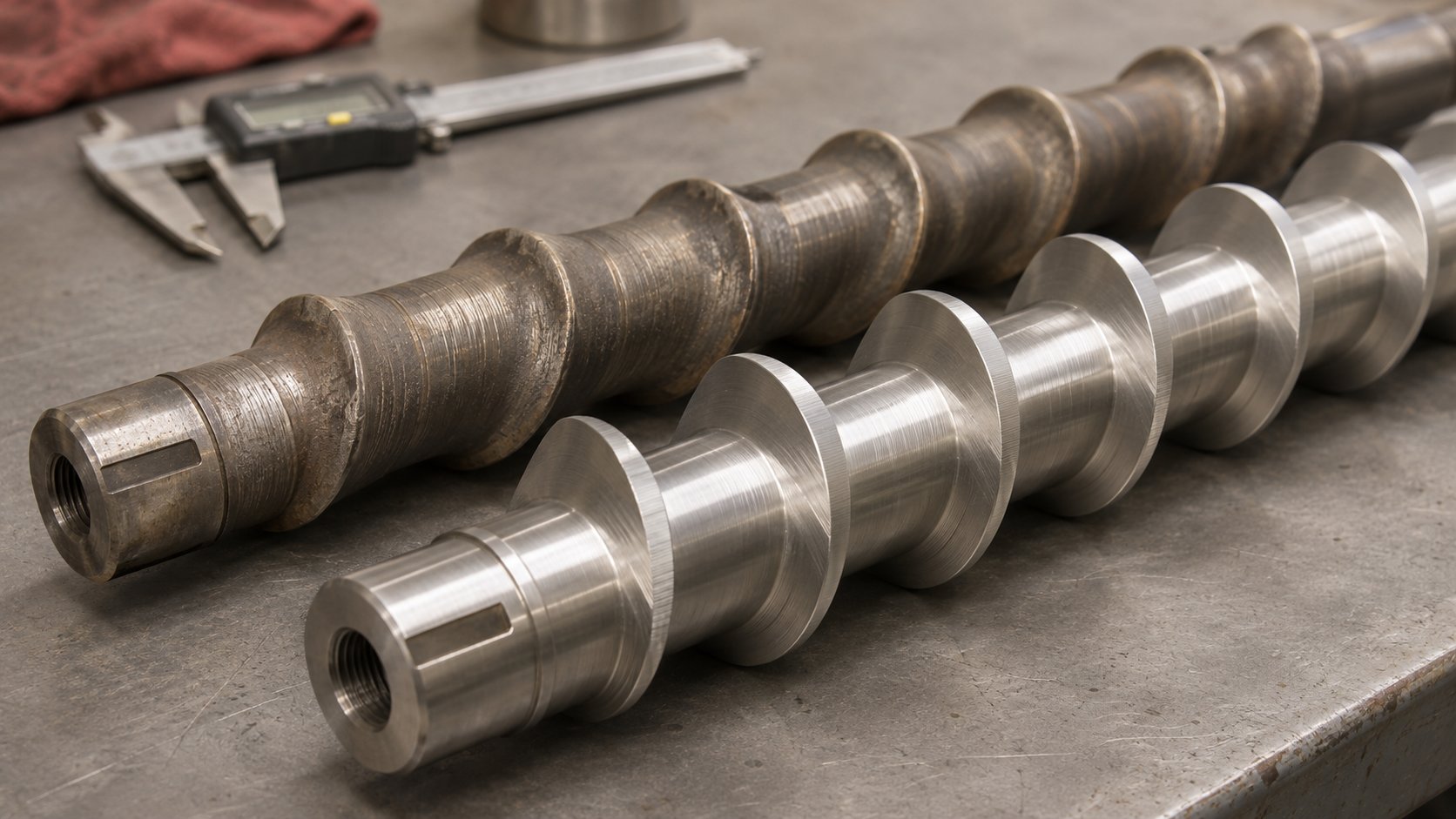
The most insidious failure on this list is screw flight wear, precisely because it is so gradual. A new stuffer screw fits tightly within the bore, with minimal clearance between the flight tips and the housing wall. As those tips wear down — accelerated by abrasive fillers like glass fiber, calcium carbonate, or mineral powders — the clearance grows and conveying efficiency drops. The operator compensates by increasing speed, which masks the wear for a while but also increases energy consumption and accelerates further deterioration. By the time the motor can no longer compensate, the screw may be severely worn and the bore itself may have sustained damage.
Inspecting and Replacing Worn Components
Scheduled inspection breaks that cycle of compensate-and-degrade. Rather than waiting for a failure to announce itself during production, pull the stuffer screw at defined intervals and measure what matters:
- Screw flight OD (outer diameter). Compare against the nominal dimension from the original drawing. Progressive reduction confirms wear and quantifies how much conveying capacity you have lost.
- Bore diameter. Measure at multiple points along the housing length. Localized wear — especially at the entry zone where melt first contacts the bore — indicates abrasive damage that may require bore re-lining or housing replacement.
- Seal condition. Inspect all gaskets, O-rings, and packing glands for compression set, cracking, or extrusion into gaps. On vacuum units, even minor seal degradation compromises the vacuum level that deep devolatilization depends on.
- Bearing play. Check radial and axial bearing clearance against the manufacturer's specification. Excessive play allows the screw to orbit within the bore, causing uneven wear patterns and accelerating both screw and bore deterioration.
How often should you inspect? A reasonable starting point for most compounding operations is every 2,000 to 4,000 operating hours — roughly quarterly on a line running two shifts. Lines processing highly abrasive materials (glass-filled compounds, mineral-loaded masterbatch) should shorten that interval, while clean, low-fill processes may safely extend it. The key is to establish a baseline with fresh components and track dimensional changes over successive inspections so you can predict replacement timing rather than react to failure.
Replacement components for a vent stuffer — screws, barrel liners, seals, bearings, and drive couplings — are standard maintenance items. Sourcing them to OEM specifications is always the first choice, ensuring exact dimensional and metallurgical compatibility. However, OEM lead times can stretch to weeks or months, especially for older or less common extruder models. When that timeline does not align with production needs, suppliers specializing in extrusion spare parts can assess worn vent stuffer screws against original specifications, working from drawings, photographs, and dimensional measurements to manufacture compatible replacements. Companies like NANHAIYA review machine details and worn samples to evaluate part compatibility and manufacturing feasibility before quoting — a practical resource when OEM channels are slow or when the original manufacturer no longer supports the equipment. Bonnot's parts program illustrates the same principle from the OEM side: they have retained engineering drawings for every machine built since 1891, enabling replacement part production for even discontinued models.
Whichever sourcing path you choose, the documentation you prepare makes the difference between a smooth replacement and a frustrating mismatch. Have these ready before contacting any supplier: the extruder make and model, barrel section number, vent port dimensions, original part drawings if available, photographs of the worn component showing the wear pattern, and critical dimensions measured from the actual part. That package gives any competent manufacturer — OEM, aftermarket specialist, or local machine shop — what they need to deliver a vent stuffer screw or housing that fits and performs correctly from the first installation.
Keeping a disciplined inspection and replacement schedule is what separates lines that run reliably from those that lurch between emergency repairs. It is also what protects the throughput and product quality gains that a properly functioning unit delivers every shift. Those gains become even more critical as the industry moves toward feedstocks and formulations that push devolatilization demands higher than conventional compounding ever did.
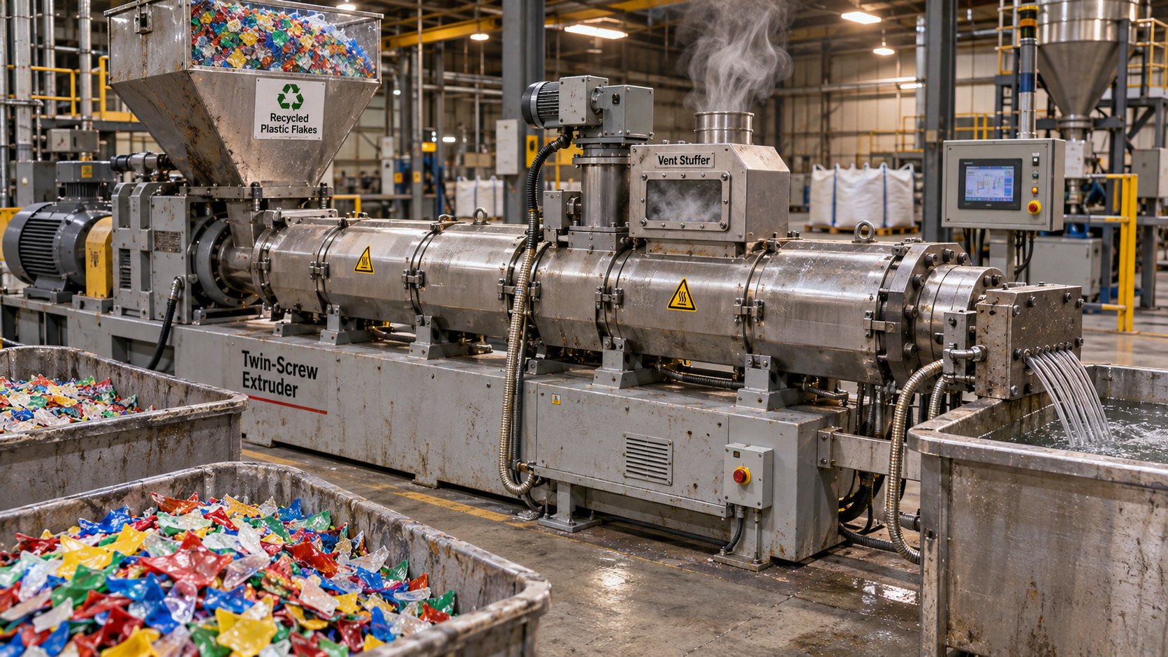
Vent Stuffers in Recycling and Emerging Applications
Conventional compounding of virgin resins is where most processors first encounter vent flow problems — and where vent stuffers have earned their reputation as reliable production equipment. But the applications driving the strongest growth in devolatilization demand are not conventional at all. Recycled plastics, bio-based polymers, natural fiber composites, and reactive extrusion processes all generate volatile loads and melt behaviors that push far beyond what a standard open vent port can handle. For processors entering these markets, understanding why these feedstocks make a vent stuffer not just helpful but essential is the difference between commercially viable throughput and a line that spends more time shut down for vent cleaning than it does producing pellets.
Vent Stuffers in Recycled Plastics Processing
Recycled plastics arrive at the extruder carrying a history that virgin resin never has. Post-consumer polypropylene flakes from mixed packaging streams, for instance, contain residual printing inks, adhesive residues, food contamination, absorbed household chemicals, and moisture — all of which become volatile organic compounds (VOCs) once the material reaches melt temperature. A 2025 study from Leibniz University Hanover demonstrated this vividly by connecting a real-time mass spectrometry system to the vacuum dome of a twin-screw extruder processing post-consumer PP. The researchers detected limonene, ethanol, and dozens of other volatile species streaming from the melt during degassing — and critically, the VOC concentration scaled directly with the proportion of recycled content in the feed. When the recycled fraction increased from 15% to 41%, the total gas-phase emissions climbed proportionally, and signal fluctuations grew larger, reflecting the inherent inhomogeneity of post-consumer waste streams.
That inhomogeneity is exactly what makes recycled plastics so challenging for vent zone management. With virgin resin, the volatile load is predictable — you set your process once and the vent zone stays stable. With post-consumer recyclate, the contamination profile shifts from batch to batch, sometimes from minute to minute within a single batch. One section of flake carries heavy ink residue; the next is relatively clean; the one after that is loaded with adhesive. Each surge in volatile content creates a corresponding surge in vapor volume at the vent, and those vapor surges entrain melt and carry it upward. The Leibniz study noted that even under controlled laboratory conditions with a steady 16 kg/h feed rate, fluctuations in detected VOC concentration were significantly higher for post-consumer material than for deliberately contaminated virgin resin — confirming that real-world recycled feedstocks produce erratic, unpredictable degassing behavior.
For a mechanical recycling line running at commercial throughput — hundreds of kilograms per hour rather than the 16 kg/h lab scale — these vapor surges are far more intense. The vent stuffer becomes the only reliable way to keep material in the barrel during peak volatile release moments while still allowing the vacuum system to pull contaminants from the melt. Without it, processors face a painful tradeoff: reduce throughput to keep the vent zone stable, or accept frequent shutdowns for vent cleaning. Neither option supports the economics that make recycling commercially viable.
Bio-Based Polymers and Natural Fiber Composites
The challenge with bio-based materials is not contamination — it is chemistry. Polymers like PLA, PHA, and starch blends carry inherent moisture sensitivity and narrow thermal processing windows. Natural fiber reinforcements — wood flour, hemp, flax — compound the problem by releasing their own moisture and decomposition gases when exposed to melt temperatures.
Consider PHBV (poly-3-hydroxybutyrate-co-3-hydroxyvalerate), a biodegradable polyester gaining traction as an alternative to conventional packaging plastics. Research published in Polymers examined PHBV biocomposites filled with 15% flax and hemp fibers, comparing single-screw and twin-screw extrusion methods. The twin-screw extruder produced composites with lower porosity and lower water absorption — advantages the researchers attributed directly to the degassing zone built into the twin-screw screw profile. The implication is clear: effective venting during compounding is not optional for these materials. It directly determines the physical quality of the finished product.
Natural fibers intensify the venting challenge in two ways. First, cellulose fibers begin degrading thermally at temperatures as low as 200 degrees C, releasing moisture and decomposition gases precisely in the temperature range where most bio-based matrices are processed. The same research noted that fiber degradation was influenced by both temperature and residence time, with longer exposure in the plasticizing system accelerating gas generation. Second, fibers change the melt rheology unpredictably. Longer fibers — preserved better in single-screw extrusion — create higher flow resistance and can bridge across vent openings, while shorter fibers from twin-screw processing increase the number of gas-releasing surfaces dispersed throughout the melt.
Leistritz, a recognized twin-screw extruder OEM, has documented natural fiber composite extrusion applications where effective venting is essential to achieving the throughputs needed for commercial production. When you combine a thermally sensitive matrix that cannot tolerate extended residence time with a fiber reinforcement actively generating gases, the vent zone has to work hard — and it has to stay clear. A vent stuffer enables processors to push these materials through at production-relevant speeds without sacrificing the degassing performance that determines whether the final part is dense and strong or porous and weak.
Reactive Extrusion and Chemical Devolatilization
Reactive extrusion adds a layer of complexity that neither recycled plastics nor bio-based composites present on their own: the volatile load is not just carried in with the feedstock — it is generated inside the barrel by the reaction itself. Grafting reactions, chain extension, controlled degradation, and polymerization processes all produce chemical byproducts that must be removed through the vent zone. These byproducts range from water and alcohols to more exotic species depending on the chemistry involved.
The combination is severe. You have a viscous, reactive melt that resists forward flow, generating localized pressure at the vent zone. Simultaneously, reaction-generated gases are expanding within that melt, creating foam and vapor surges that push material upward. Rob Jerman of Extrusion Technology and Innovations describes this phenomenon in devolatilization broadly: "When the rate of volatile removal is high, devolatilization is more of a boiling process, generating significant amounts of foam and bubbles." In reactive extrusion, that boiling behavior occurs not because the feedstock was contaminated, but because the chemistry you intentionally introduced is producing gaseous byproducts at the same location where the melt is most viscous and pressure-sensitive.
Reactive processes also tend to operate at higher melt temperatures to drive reaction kinetics, which further increases the vapor pressure of volatile byproducts. Jerman notes that "it is quite possible to have a well-designed vacuum vent and screw design run under full vacuum, only to see the residual volatiles increase as a result of unzipping or depolymerization rates exceeding the rates of devolatilization." A vent stuffer does not solve that thermodynamic challenge — but it does solve the mechanical one. By keeping the vent port clear of escaped melt, it ensures that whatever vacuum and surface-area regeneration capacity the screw design provides is actually available for volatile removal rather than being compromised by polymer clogging the vapor pathway.
Across all three of these emerging application areas — recycled plastics with their unpredictable contamination, bio-based materials with their thermal sensitivity and fiber-generated gases, and reactive extrusion with its chemically produced volatiles — the common thread is the same. The volatile load is higher, less predictable, and more process-critical than in conventional virgin compounding. Passive vent solutions that work fine for a clean polyolefin compound cannot keep pace with feedstocks that generate vapor surges strong enough to carry melt out of the barrel. The vent stuffer is what makes these processes runnable at the throughputs commercial production demands.
These forward-looking applications also raise the stakes for every topic covered earlier in this article — sizing, speed optimization, and especially maintenance. A recycling line processing post-consumer waste puts far more wear on vent stuffer components than a clean compounding operation ever will. That reality makes the practical question of sourcing the right replacement parts and keeping the unit in peak condition not just a maintenance concern, but a strategic one that directly affects whether emerging applications pencil out economically.
Putting It All Together and Sourcing the Right Parts
Every concept explored across this article — from the mechanics of vent flow to screw speed ratios to bore wear measurements — converges on a single practical question: how do you keep your vent stuffer extruder system performing reliably, day after day, across changing feedstocks and production demands? The answer depends on your role. A process engineer evaluating a new installation faces different priorities than an operator troubleshooting a unit mid-run or a purchasing manager scrambling to source a replacement screw before next week's production schedule. Each perspective deserves a clear, actionable path forward.
Key Takeaways for Process Engineers and Operators
If you take only three principles away from this entire guide, make them these:
Match vent stuffer sizing to your worst-case vent flow severity — not your average conditions. Optimize the speed ratio relative to the main extruder screw speed rather than locking in a fixed RPM. Establish a preventive inspection schedule that catches wear before it causes unplanned downtime.
Those three rules address the most common mistakes processors make. Undersizing the unit for steady-state conditions leaves no margin for the screen pack pressure spike or moisture-heavy batch that sends polymer surging toward the vent. Running the stuffer at a single speed regardless of main screw changes means the balance between material return and vapor escape is correct only at one operating point — and wrong at every other. Skipping inspections until the motor trips on overload turns a $500 screw replacement into a $5,000 emergency teardown plus lost production.
For quick reference, here is the decision framework distilled into its simplest form:
- Open vent port: Low-viscosity materials, moderate throughput, low die pressure, well-optimized screw design with adequate pumping under the vent, and no vacuum requirement.
- Vent insert or restrictor: Borderline conditions where vent flow is intermittent and mild — an intermediate fix, not a permanent solution for severe or recurring problems.
- Powered vent stuffer: High throughput, high-viscosity or heavily filled compounds, vacuum devolatilization, recycled or bio-based feedstocks with high or variable volatile loads, and any process where vent flow has caused shutdowns more than once.
Operators working with an existing unit should build a habit around the five monitoring indicators discussed earlier: visual vent port checks, motor amperage trending, downstream volatile measurement, vacuum level stability, and mechanical noise or vibration. Logging these observations creates a history that makes it far easier to distinguish a normal process drift from the early stages of component failure. When something does change — a gradual amperage climb over two weeks, for instance — you have data to support a proactive maintenance call rather than waiting for the vent to flood during a critical production run.
Sourcing Vent Stuffer Components and Replacement Parts
Wear is inevitable. Screws lose flight diameter, bores open up, seals compress and crack, bearings develop play. The question is never whether you will need replacement parts, but how quickly and accurately you can source them when the time comes. Preparation is the difference between a planned weekend swap and a two-week production bottleneck while you wait for a part that should have been on the shelf.
Before contacting any supplier — OEM, aftermarket specialist, or local machine shop — assemble this documentation package:
- Machine make and model — including the barrel section number where the vent stuffer is mounted.
- Barrel diameter and vent port dimensions — measured from the actual hardware, not assumed from catalog specifications, especially on older machines that may have been modified.
- Original part drawings — if available from the OEM or from your maintenance files. These are the gold standard for dimensional accuracy.
- Photographs of worn parts — showing the wear pattern, any damage, and the overall condition of mating surfaces. A clear photo of a worn screw flight tells a manufacturer more about your application severity than any written description.
- Critical dimensions measured from the actual part — flight OD, root diameter, pitch, overall length, shaft bore, and keyway dimensions. Even when drawings exist, confirming measurements against the physical part catches discrepancies from prior rework or non-standard replacements.
With that package in hand, you have three parallel sourcing channels worth pursuing simultaneously:
OEM replacement parts are the first check. The original extruder manufacturer holds the design authority and can supply exact-match components with guaranteed dimensional and metallurgical compatibility. The tradeoff is lead time and cost — OEM channels often quote weeks or months for delivery, especially for older or less common vent stuffer extruder models that are no longer in active production. If your machine is still well-supported, this is the most straightforward path.
Aftermarket extrusion spare parts suppliers fill the gap when OEM availability is slow or when the original manufacturer no longer supports the equipment. Companies like NANHAIYA review machine details, drawings, worn samples, photographs, and critical dimensions to assess part compatibility and manufacturing feasibility before quoting. While their product page lists standard extrusion and injection molding components — screw tips, check rings, non-return valves, injection nozzles, and thermocouples — specialized items like vent stuffer screws and housings can be submitted as inquiries for feasibility assessment. This inquiry-based approach is particularly useful for custom or hard-to-find components where no off-the-shelf replacement exists.
Local precision machining shops offer the fastest turnaround for straightforward components — a replacement screw with known dimensions and standard metallurgy, for example. The limitation is that most general machine shops lack deep experience with the specific metallurgies, heat treatments, and surface finishes that extrusion wear parts demand. A screw machined from the wrong steel grade or improperly heat-treated will wear out in a fraction of the expected service life. If you go this route, provide the metallurgy specification explicitly and verify that the shop can source and process the correct material.
The smartest approach is not to choose one channel exclusively but to maintain relationships across all three. Request OEM quotes for critical spares and keep commonly worn items — screws, seals, bearings — in your on-site inventory at quantities that cover at least one planned replacement cycle. For components with long OEM lead times, get a parallel quote from an aftermarket supplier so you have a backup path already priced and assessed for feasibility. That way, when a quarterly inspection reveals a screw approaching its wear limit, you are ordering from inventory rather than scrambling to find a source.
Ultimately, a vent stuffer is only as good as the attention it receives — from initial sizing and speed optimization through daily monitoring and timely parts replacement. The processors who treat it as a core part of their extrusion system, rather than an afterthought bolted to the barrel, are the ones who run higher throughputs, produce cleaner product, and avoid the costly shutdowns that vent flow inflicts on underprepared lines. Whether you are evaluating your first installation, tuning a unit that is not quite keeping up, or sourcing a replacement screw for a machine that has been running hard for years, the principles are the same: size it right, run it smart, maintain it early, and source parts before you need them.
Frequently Asked Questions About Vent Stuffers
1. What is the purpose of a vent stuffer on a twin-screw extruder?
A vent stuffer is a motor-driven auxiliary screw device mounted at the vent port of a twin-screw extruder. Its primary purpose is to prevent molten polymer from escaping through the vent opening during devolatilization — a problem known as vent flow. The rotating screw pushes any rising melt back into the barrel while keeping the vapor pathway completely open, so moisture, trapped air, residual monomers, and decomposition gases can still escape freely. Without one, processors running high-viscosity melts, heavily filled compounds, or vacuum devolatilization setups risk contaminated product, material waste in vacuum lines, and unplanned shutdowns for vent cleaning.
2. How do I know if my extruder needs a vent stuffer or if an open vent port is enough?
An open vent port is typically sufficient when you are processing low-viscosity materials at moderate throughputs with a well-optimized screw design and low die pressure. If your line consistently operates with starve-fed screw channels that keep melt well below the vent opening, passive venting works fine. However, a powered vent stuffer becomes necessary when you encounter high throughput rates, high-viscosity or heavily filled polymers, aggressive downstream mixing elements, elevated die or screen pack pressure, high volatile loads from recycled or hygroscopic resins, or vacuum devolatilization. If vent flow has caused more than one unplanned shutdown, that is a strong signal passive venting has reached its limit.
3. What is the correct speed ratio between a vent stuffer and the main extruder screw?
There is no single universal ratio, but a practical starting point is roughly 20 to 40 percent of the main extruder screw RPM. Begin at a moderate speed and increase incrementally while monitoring two things: the vent port for any material creeping upward and the residual volatile content in the extrudate downstream. The target is the lowest stuffer speed that eliminates visible vent flow without restricting vapor escape. Running the stuffer too slow allows polymer to escape, while running it too fast can block the vapor pathway and reduce devolatilization efficiency. Importantly, this ratio must be re-evaluated whenever main screw speed, feed rate, or screw element configuration changes.
4. How often should vent stuffer screws and components be inspected?
A reasonable starting interval for most compounding operations is every 2,000 to 4,000 operating hours — roughly quarterly on a two-shift production line. Key inspection points include screw flight outer diameter compared to OEM specifications, bore diameter measured at multiple locations, seal condition for compression set or cracking, and bearing play. Lines processing highly abrasive materials such as glass-filled or mineral-loaded compounds should shorten this interval, while clean, low-fill processes can safely extend it. Establishing a dimensional baseline with fresh components and tracking changes over successive inspections allows you to predict replacement timing proactively.
5. Where can I source replacement vent stuffer screws if OEM parts have long lead times?
Three parallel channels are worth pursuing. First, check OEM availability for exact-match parts with guaranteed compatibility. Second, contact aftermarket extrusion spare parts suppliers such as NANHAIYA (nhyscrews.com), who review machine details, drawings, worn samples, photos, and dimensions to assess manufacturing feasibility for custom or hard-to-find components like vent stuffer screws. Third, consult local precision machining shops for straightforward components with known dimensions, though you must provide explicit metallurgy and heat treatment specifications. Before contacting any supplier, prepare documentation including machine make and model, barrel diameter, vent port dimensions, original drawings, photographs of worn parts, and critical measured dimensions.
Written by
Nanhaiya Technical Team
Zhoushan Nanhaiya Plastic Machinery Co., Ltd.
The Nanhaiya technical team supports screw and barrel manufacturing projects through application review, technical communication, custom manufacturing coordination, and production and quality control.
Discuss Your Application
Related Articles
More insights on screw barrel technology and plastics processing.
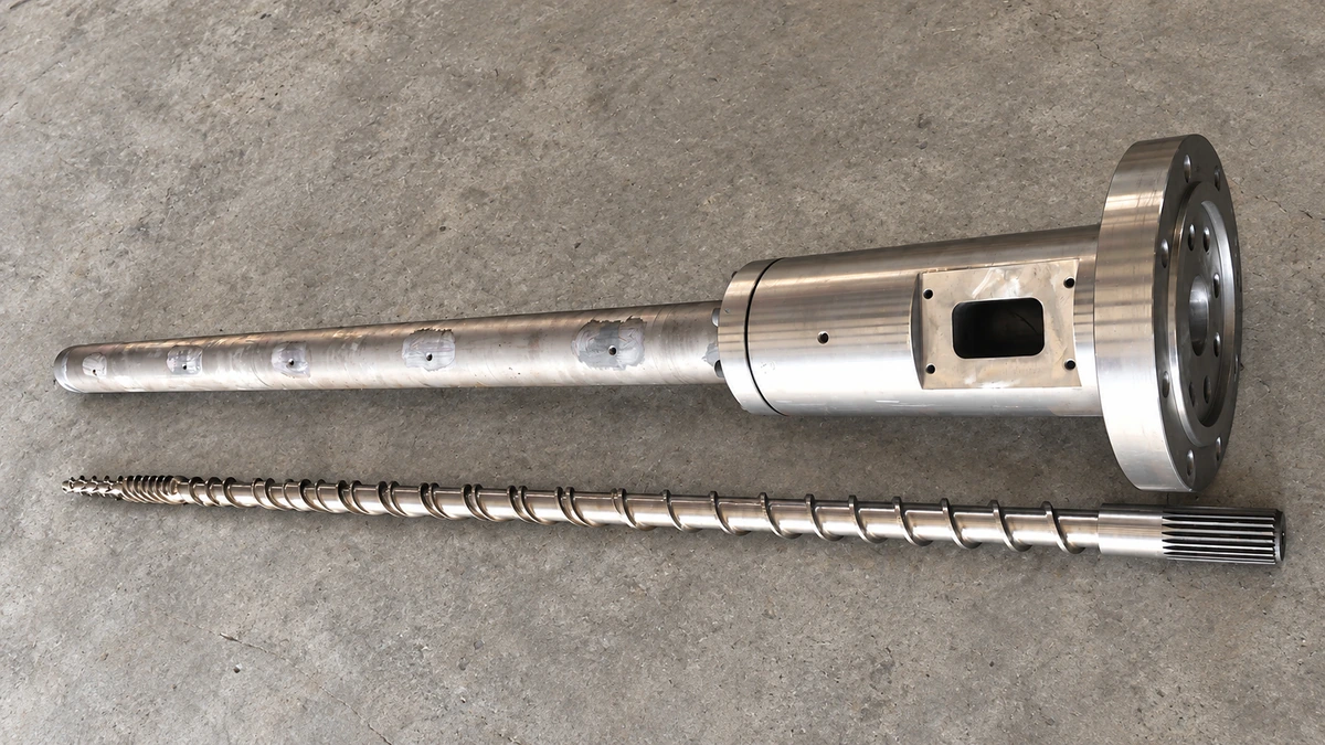
Why Your Single Screw Extruder Design Causes Extrusion Defects
Nov 13, 2026
Learn how single screw extruder design parameters—L/D ratio, compression ratio, channel depth, and mixing elements—affect melt quality, throughput, and defects.
Read Article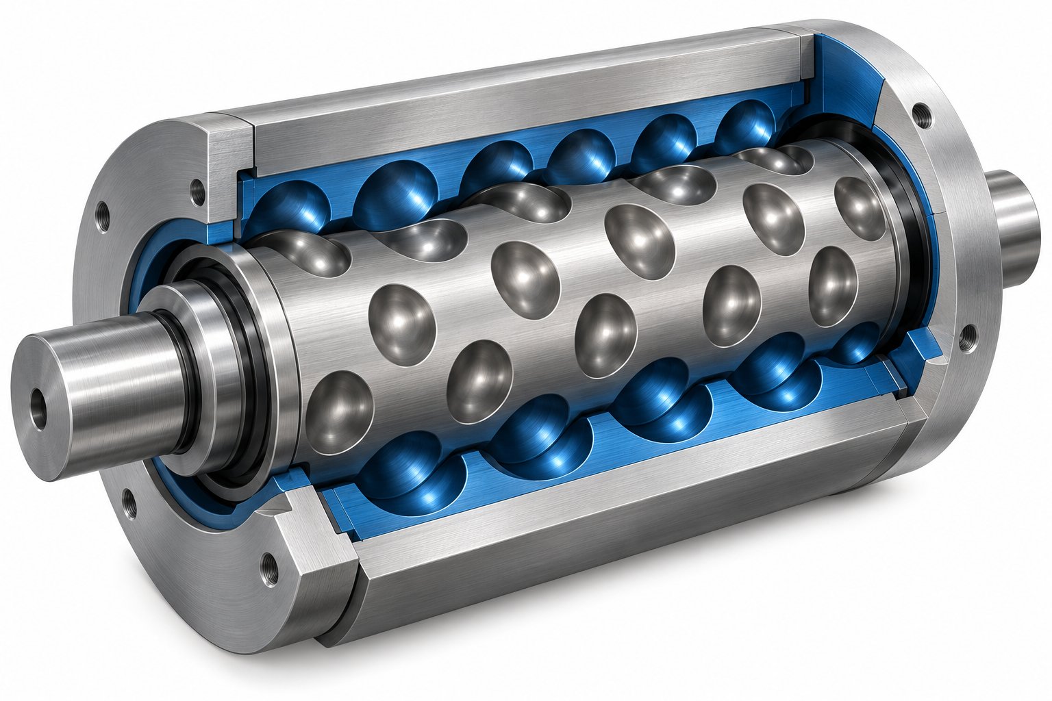
Cavity Transfer Mixer: The Blender Your Extruder Didn't Know It Needed
Nov 13, 2026
Learn how a cavity transfer mixer (CTM) upgrades single-screw extruder mixing. Covers working principles, key parameters, integration, applications, and comparisons.
Read Article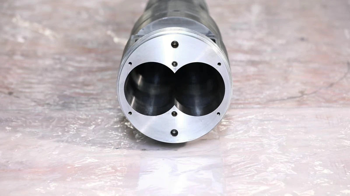
Extruder Barrel Alignment Decoded: Tolerances Most Plants Miss
Nov 13, 2026
Learn extruder barrel alignment tolerances, laser procedures, thermal offsets, and proactive schedules most plants miss — for single-screw and twin-screw lines.
Read ArticleLooking for something else?
Search by material, symptom or product and jump straight to the relevant page.
These are navigation suggestions based on keyword matching — not a quotation, not a delivery commitment, and not a substitute for engineering review. Final specification is confirmed by our engineers against your drawings and processed material.
Need help with screw barrel selection?
Share your machine model, processed material and application. Our team can help with pricing and technical support.