

What Is a Cavity Transfer Mixer
Imagine your single-screw extruder does a fantastic job melting and pushing polymer forward — but the color masterbatch coming out the other end looks streaky, or your additive blend is far from uniform. The extruder is doing its job as a conveyor. It just isn't much of a mixer. That's exactly the gap a cavity transfer mixer is built to fill.
Defining the Cavity Transfer Mixer
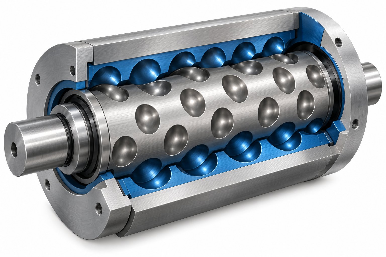
A cavity transfer mixer — often shortened to CTM — is a specialized add-on mixing device mounted at the discharge end of a single-screw extruder. It consists of a cylindrical rotor housed inside a cylindrical stator, and both surfaces are machined with rows of hemispherical or semi-cylindrical cavities. The key detail: those cavities are staggered, so as the rotor turns, material is forced to transfer back and forth between rotor and stator cavities in rapid succession. Each transfer splits, reorients, and recombines the polymer melt, delivering both distributive and dispersive mixing in a compact package.
A cavity transfer mixer (CTM) is a rotor-stator mixing device featuring staggered rows of hemispherical cavities that force polymer melt through successive cavity-to-cavity transfers, producing high-quality distributive and dispersive mixing as a bolt-on addition to single-screw extruders.
The concept was designed from the start as an accessory — not a replacement. The extruder upstream handles solids conveying, melting, and pressurization. The CTM handles the final, critical mixing stage before the die. As noted in US Patent 4,750,842, the device integrates directly with the extruder, and the rotor can even be driven by the extruder screw shaft itself.
Why CTMs Matter in Polymer Processing
Here's the core problem. Single-screw extruders are workhorses — reliable, relatively simple, and cost-effective for melting and conveying thermoplastics. But they are inherently limited when it comes to mixing. The drag flow inside a single-screw channel produces some shear, yet it falls short for applications demanding tight pigment dispersion, uniform additive distribution, or thorough blending of multi-component formulations.
The conventional answer? Switch to a twin-screw extruder. Twin-screw systems offer superior mixing flexibility through modular screw elements — kneading blocks, mixing zones, and multiple feeding points. But that upgrade comes with significantly higher capital cost, greater mechanical complexity, and increased maintenance demands.
A CTM offers a middle path. By bolting one onto an existing single-screw line, processors can dramatically improve mixing quality without scrapping proven equipment or absorbing the expense of a twin-screw system. It's an engineering solution that targets the specific weakness of single-screw extrusion while preserving its strengths.
Despite this practical value, detailed information on CTMs remains scattered across academic journals, patent filings, and computational fluid dynamics studies — much of it behind paywalls. This guide pulls that knowledge together into an accessible, practitioner-focused resource. You'll find clear explanations of how these devices work, what parameters drive their performance, how they integrate with extruder systems, where they're applied industrially, and how they compare to alternative mixing technologies like Maddock mixers, static mixers, and twin-screw extruders.
The story begins, naturally, with where the CTM came from — and the engineering problem that sparked its invention.
History and Invention of the Cavity Transfer Mixer
Every engineering device has an origin story — a specific frustration that pushed someone to design something new. For the cavity transfer mixer, that frustration was straightforward: single-screw extruders couldn't mix well enough, and twin-screw systems were too expensive for many processors. Researchers in the 1980s asked a practical question — could a compact, bolt-on device close that mixing gap?
Invention and Early Development
The CTM concept emerged from work at the Rubber and Plastics Research Association of Great Britain (RAPRA) during the early-to-mid 1980s. The goal was clear: create a device that could deliver high-quality distributive mixing without requiring processors to abandon their existing single-screw extrusion lines. Early designs centered on the rotor-stator principle — staggered rows of hemispherical cavities that would force material through repeated splitting and recombination events as the rotor turned inside the stator.
An important precursor appears in US Patent 4,419,014, filed in 1980 by the Rubber and Plastics Research Association and granted in 1983, which described an extruder mixer using cavity-based transfer principles. This laid groundwork for what followed. By the mid-1980s, the concept had matured enough for industrial integration. US Patent 4,750,842, filed in 1986 and granted in 1988, described a complete mixing apparatus that combined a cavity transfer mixer with an extruder system. Inventor Elwyn Huddleston's design detailed how the CTM rotor could be driven directly by the extruder screw shaft — a mechanical simplification that made retrofit installation far more practical. The patent was assigned to The Kendall Company and Okabe Co., signaling early commercial interest in the technology.
Foundational academic publications during the same period — including work presented in Materials & Design in 1987 — introduced analytical frameworks for understanding the mixing behavior inside these devices. These papers gave engineers a language and a set of models for predicting how cavity geometry, row count, and rotational speed would influence mixing quality. The CTM was no longer just a clever mechanical idea; it had a theoretical backbone.
From Academic Research to Industrial Adoption
The gap between a working prototype and an optimized industrial tool is often measured in decades of research. For the CTM, computational modeling played a pivotal role in bridging that gap. Among the most significant contributions came from the Polymer Technology Group at Eindhoven University of Technology (TU/e), where a team led by Giovanna Grosso, Martien Hulsen, and Patrick Anderson developed a fully three-dimensional model of the device. Their work, published in the AIChE Journal in 2018, used a finite element solver to compute the transient velocity field inside the CTM and applied mapping methods to track concentration field evolution — essentially visualizing exactly how material gets mixed inside the cavities over time.
What made this research particularly valuable was its parametric scope. Grosso and colleagues ran simulations assessing how geometrical and operational variables — cavity size, number of cavities per row, rotational speed — affect mixing outcomes. One key finding: the number of cavities per row should be limited and the cavity size kept relatively large to guarantee good mixing quality. This kind of insight, grounded in rigorous computation rather than trial-and-error, gave equipment designers concrete guidance for optimizing real hardware.
Other research groups extended the analysis further, examining residence time distributions, shear rate profiles, and the interplay between dispersive and distributive mixing within the cavity geometry. Each study refined the design rules — adjustments to cavity depth, row spacing, and land width that incrementally improved performance.
The cumulative result of this academic effort was a device that filled a very specific technological niche. A well-designed CTM could deliver mixing quality approaching that of twin-screw extruders while preserving the mechanical simplicity and lower capital cost of single-screw lines. For processors already running single-screw equipment, this meant a realistic upgrade path — better mixing without a full equipment overhaul.
Understanding where the CTM came from sets the stage for the more practical question: what actually happens to the polymer melt inside those staggered cavities, and why does that geometry work so well?
How a Cavity Transfer Mixer Works
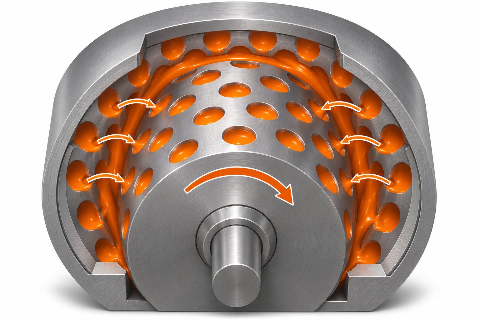
Picture a cylinder spinning inside a barrel — nothing unusual for extrusion equipment. But look closer at both surfaces, and you'll notice something distinctive. Each one is covered with rows of cup-like depressions, offset from one another in a deliberate pattern. That staggered arrangement is the entire secret behind why a cavity transfer mixer transforms mediocre single-screw mixing into something far more effective.
Rotor-Stator Cavity Geometry
The physical structure of a CTM is deceptively simple. A cylindrical rotor sits inside a close-fitting cylindrical stator (the barrel housing). Both the outer surface of the rotor and the inner surface of the stator are machined with rows of hemispherical cavities — think of a muffin tin wrapped around a cylinder, then imagine a matching but offset muffin tin lining the inside of the barrel surrounding it.
The critical design feature is the stagger. Rotor cavities and stator cavities are not aligned. Instead, they're offset so that as the rotor turns, each rotor cavity progressively overlaps with a stator cavity, then moves past it, then overlaps with the next one. Between the cavities, flat raised surfaces called "lands" create narrow gaps where the rotor and stator nearly touch. These lands serve double duty: they seal off individual cavities during rotation and generate intense shear fields as material passes over them.
| Component | Feature | Function |
|---|---|---|
| Rotor | Rows of hemispherical cavities on outer surface; rotates with extruder shaft | Carries material forward and forces it into stator cavities during rotation; land surfaces generate shear |
| Stator | Rows of hemispherical cavities on inner surface; remains stationary | Receives material from rotor cavities and holds it until the next rotor cavity aligns; land surfaces generate opposing shear |
| Lands (both surfaces) | Flat regions between cavities; create a narrow rotor-stator gap | Provide high-shear zones for dispersive mixing; control the transfer of material between cavities |
Imagine you're holding two egg cartons face-to-face, but shifted so the cups don't line up. Slide one carton sideways and any material sitting in a cup on one side gets pushed into a cup on the other. That back-and-forth transfer — repeated across multiple rows — is the core of how the device operates.
The Mixing Mechanism Explained
Two distinct types of mixing happen simultaneously inside the device, and understanding both is key to appreciating why the geometry works so well.
Distributive mixing is the spreading and recombining action. Every time material transfers from a rotor cavity to a stator cavity (or vice versa), the melt stream gets split, reoriented, and folded back together. Each transfer event increases the number of material layers — called striations — exponentially. After just a few rows of cavities, a single initial blob of colorant or additive has been divided into thousands of thin layers distributed throughout the polymer matrix. The result is spatial uniformity.
Dispersive mixing is the breakdown action. As material squeezes across the narrow land gaps between cavities, it experiences high shear stress. That stress is what breaks apart agglomerates — clumps of pigment particles, undissolved additive granules, or gels. The tighter the gap and the faster the rotor spins, the higher the shear force applied to those agglomerates.
Here's how a single mixing cycle unfolds, step by step:
- Polymer melt enters a cavity on the rotor, carried by the upstream pressure from the extruder.
- As the rotor turns, the filled rotor cavity rotates into alignment with an open stator cavity.
- Material transfers across the narrow land gap into the stator cavity, experiencing high shear during the crossing.
- The rotor continues turning, and the now-filled stator cavity comes into alignment with the next rotor cavity downstream.
- Material transfers back to the rotor side, again passing through a shear zone on the land surface.
- This transfer-shear-transfer cycle repeats for every row of cavities along the length of the device.
Each row effectively doubles (or more) the number of striations from the previous row. So a CTM with six rows of cavities doesn't just mix six times better than a single row — the improvement is exponential. Research from the Polymer Technology Group at Eindhoven University of Technology, using fully three-dimensional finite element modeling and mapping methods to track concentration evolution, confirmed this compounding effect. Their simulations showed that each additional row of cavities multiplies the number of striations, dramatically improving mixing quality. The same study found that keeping the number of cavities per row limited while using relatively large cavity sizes produced the best mixing outcomes — a counterintuitive result that underscores why computational modeling has been so valuable in optimizing these devices.
The practical takeaway is straightforward. The geometry does the heavy lifting. Every rotation of the rotor triggers dozens of splitting, shearing, and recombination events across all cavity rows simultaneously. Material that enters one end as a poorly mixed stream exits the other as a far more homogeneous melt — without additional heating elements, complex screw modifications, or extra mechanical drives.
Of course, describing how the mixing happens raises an immediate follow-up question: which design variables and operating conditions have the greatest influence on how well it works? Cavity depth, row count, rotor speed, and material viscosity all play distinct roles — and getting the balance right is where engineering judgment meets process optimization.
Key Operating Parameters That Affect CTM Performance
Knowing that the geometry does the heavy lifting is one thing. Knowing which knobs to turn — and how far — is what separates a well-optimized cavity transfer mixer from one that underperforms or overheats the melt. Academic research, particularly the fully three-dimensional computational studies from Eindhoven University of Technology, has quantified how specific design and operating variables shift the balance between mixing quality, energy consumption, and material integrity. Here's what the findings mean in practical terms.
Number of Cavity Rows and Cavity Geometry
If you could change only one thing about a CTM to improve its mixing performance, add more cavity rows. Each row forces the polymer melt through another round of splitting, shearing, and recombination. Because the striation count multiplies with every row rather than simply adding to it, the relationship between row count and mixing quality is exponential. A device with four rows doesn't mix twice as well as one with two rows — it mixes many times better.
Cavity shape matters, too. Hemispherical cavities are the most common geometry, but semi-cylindrical profiles are also used. Hemispherical cavities tend to produce smoother flow transitions during material transfer, reducing the likelihood of dead zones where polymer can stagnate and degrade. Cylindrical cavities, by contrast, may offer slightly sharper shear gradients at the cavity edges, but they carry a higher risk of creating pockets where material lingers too long.
Cavity depth and diameter interact in important ways. Deeper cavities hold more material per transfer event and increase the residence time within each cavity. That extra dwell time can be beneficial for processes requiring prolonged contact — think reactive extrusion where conversion depends on mixing duration. But push the depth too far and you create stagnant zones at the cavity floor, leading to thermal degradation of heat-sensitive polymers. Shallower cavities flip the equation: shorter residence time, more intense shear as material gets squeezed across the lands more aggressively, and less risk of stagnation.
One finding from the Grosso, Hulsen, and Anderson study deserves special attention. Their simulations showed that the number of cavities per row should be limited and the cavity size kept relatively large to guarantee good mixing quality. Packing too many small cavities into a single row actually degrades performance — the material doesn't fully transfer between cavities before the next alignment occurs, short-circuiting the splitting mechanism that makes the device effective in the first place.
Rotor Speed, Throughput Rate, and Material Viscosity
Geometry sets the stage, but operating conditions determine the performance you actually get on the production floor.
Rotor speed is the most direct lever for adjusting mixing intensity. Faster rotation increases the shear rate in the land gaps, which strengthens dispersive mixing — agglomerates break down more effectively under higher stress. It also accelerates the rate of cavity-to-cavity transfers, packing more splitting events into any given time window. The trade-off? Higher rotor speeds dump more mechanical energy into the melt as heat. For polymers with narrow processing windows — PVC, certain bioplastics, or thermally sensitive engineering resins — excessive speed can push melt temperatures into degradation territory.
Throughput rate interacts with rotor speed in a way that's easy to overlook. At a constant rotor speed, increasing throughput means each parcel of material spends less time inside the device. Fewer effective cavity transfers occur per unit of material, and mixing quality drops. You can visualize it this way: imagine a line of people passing through a revolving door. Speed up the line without spinning the door faster, and some people slip through without completing a full rotation. The same principle applies to polymer melt rushing through the cavities. Research into residence time distribution within cavity transfer mixers has confirmed that operating conditions directly shape how long material dwells inside the device — and that distribution affects final product uniformity.
Material viscosity is the variable you don't choose — it comes with the polymer and the processing temperature. Highly viscous melts experience greater shear stress as they squeeze across the narrow land gaps, which is excellent for dispersive mixing. Pigment agglomerates and filler clusters break apart more readily under that stress. However, high viscosity also demands more torque from the drive system. If the extruder screw shaft powers the CTM rotor — as described in many retrofit configurations — the motor and gearbox must handle the additional mechanical load without stalling or overheating.
Lower-viscosity materials flow more freely through the cavities, reducing energy input and torque demand. The downside is that the shear forces in the land gaps may not be sufficient for demanding dispersive tasks like breaking apart tightly bound pigment agglomerates. For these materials, the CTM's value shifts more toward distributive mixing — spreading and folding the melt rather than crushing clusters.
Here's a concise summary of how each parameter influences what you get out of the device:
- Number of cavity rows: More rows exponentially increase striation count and overall mixing quality; the single most impactful geometric variable.
- Cavity size and count per row: Fewer, larger cavities per row outperform many small cavities; oversized rows cause incomplete transfers.
- Cavity depth: Deeper cavities extend residence time (useful for reactive processes) but risk stagnant zones; shallower cavities intensify shear.
- Cavity shape: Hemispherical profiles promote smoother flow and fewer dead spots; cylindrical shapes may increase localized shear but raise degradation risk.
- Rotor speed: Higher speed improves both dispersive and distributive mixing but increases melt temperature — critical for heat-sensitive polymers.
- Throughput rate: Higher throughput at constant rotor speed reduces effective cavity transfers per material parcel, lowering mixing quality.
- Material viscosity: Higher viscosity boosts dispersive shear stress but increases torque demand; lower viscosity favors distributive mixing with less energy input.
Getting these parameters right is essential — but even a perfectly tuned CTM won't perform well if the extruder feeding it can't deliver the right pressure, temperature, and melt consistency. That upstream connection between the screw and the mixer is where integration engineering becomes just as important as the mixer design itself.
How CTMs Integrate with Single-Screw Extruder Systems
A cavity transfer mixer sitting on a shelf is just a precision-machined rotor inside a stator housing. It only becomes useful once it's connected to an extruder that can feed it molten polymer under pressure — and that connection is far more than a matter of bolting flanges together. The upstream screw, the barrel temperature profile, the motor's torque capacity, and the die downstream all have to work in concert with the mixer. Getting this integration right determines whether you unlock the full mixing potential of the device or create a bottleneck that chokes your line.
Mounting a CTM on a Single-Screw Extruder
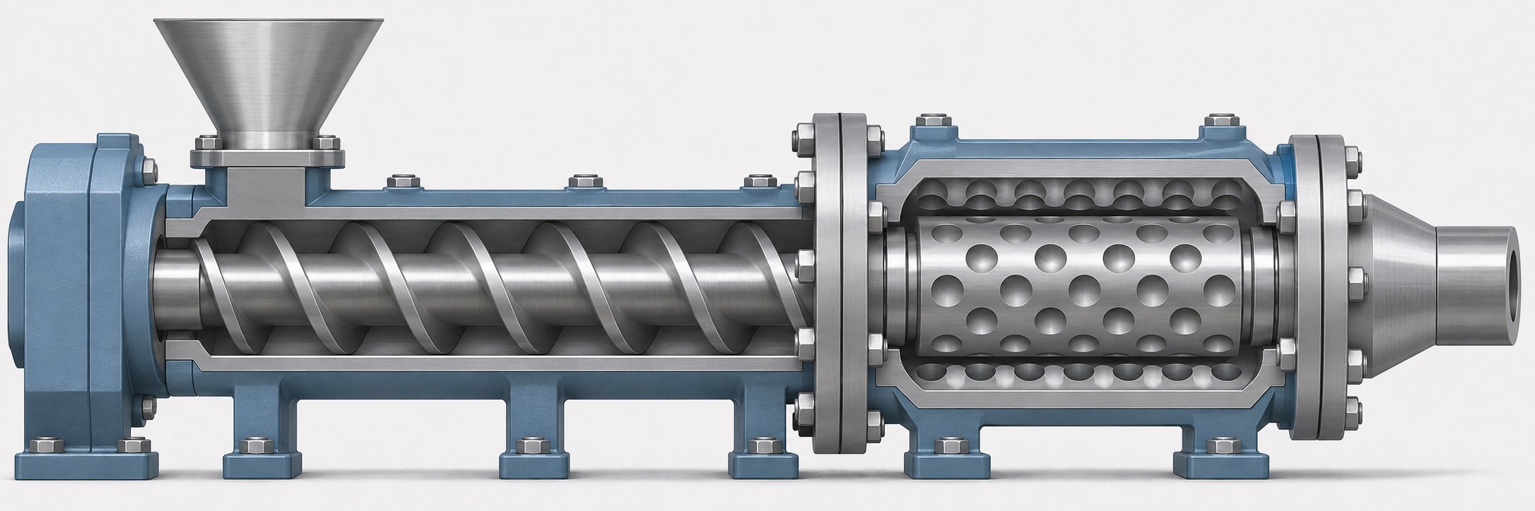
The most common installation places the CTM unit at the discharge end of a single-screw extruder, positioned between the screw tip and the die. In this configuration, the extruder handles everything it already does well — receiving raw material through the hopper, conveying solid pellets forward, melting them through barrel heating and shear, and building pressure to push the melt downstream. The CTM takes over at the final stage, receiving that pressurized melt and subjecting it to the cavity-to-cavity transfer process before it reaches the die.
Sounds straightforward? Mechanically, it largely is. The mixer housing bolts to the extruder barrel's discharge flange, and the die attaches to the opposite end of the CTM. Material flows in a straight path: screw channel to mixer inlet, through the cavity rows, out the mixer outlet, and into the die.
The rotor drive arrangement is where things get clever. As described in US Patent 4,750,842, the CTM rotor can be driven directly by the extruder screw shaft itself. The screw extends into the mixer section, coupling mechanically to the rotor so that both turn at the same speed without requiring a separate motor or gearbox. This simplifies the mechanical setup considerably — no extra drive system, no additional controls, and no independent speed adjustment to worry about. The trade-off is that rotor speed is locked to screw speed, which limits flexibility if the optimal mixing speed differs from the optimal screw speed for conveying and melting.
An alternative approach appears in later patent literature. US Patent 6,588,925, filed by Robin Hilder and assigned to Kaltor Ltd, describes a rotor-stator mixer that can be positioned either at the discharge end of the screw or intermediate between two screw sections. In the intermediate configuration, a rear screw section feeds material into the mixer, and a front screw section downstream re-pressurizes the mixed melt before the die. This split-screw design offers an important advantage: the front screw can rebuild pressure lost as material passes through the tortuous mixing paths inside the device, ensuring stable flow through the die even when the mixer imposes significant back-pressure.
The Kaltor patent also introduces a practical modularity concept. The mixer housing is assembled between flanged barrel sections using readily releasable bolted connections, allowing operators to swap one mixer for another with different cavity geometries. Imagine running a color masterbatch in the morning that demands aggressive dispersive mixing, then switching to a polymer blend in the afternoon that needs gentler distributive action — the ability to change mixer inserts without disassembling the entire line makes that transition realistic. As the patent notes, "mixing geometry and hence mixing effects can be changed by replacing the relatively inexpensive inserts rather than the entire barrel."
Screw Design Considerations for CTM Integration
Here's where many processors underestimate the challenge. Adding a CTM to the end of your extruder introduces additional flow resistance. The polymer melt now has to travel not just through the barrel and die, but through multiple rows of staggered cavities with narrow land gaps. That resistance shows up as back-pressure — and if the extruder screw can't generate enough pressure to overcome it, throughput drops, the melt channel upstream floods, and process stability collapses.
The extruder screw must be designed — or at minimum, evaluated — with the CTM's pressure requirements in mind. Several geometric features of the screw directly influence whether the system works as an integrated whole or fights itself.
Flight depth is a primary factor. Shallower metering-section flights build higher discharge pressure because the reduced channel volume compresses the melt more aggressively. If your existing screw has deep metering flights optimized for high output at low back-pressure, it may struggle to push material through the added resistance of the CTM. A screw with a higher compression ratio — the ratio of feed-section channel depth to metering-section depth — is better equipped for the job, as emphasized in NC State Extension's guide on screw profile design, which notes that channel depth decreases progressively from conveying to compression to metering zones specifically to build pressure.
Existing mixing sections on the screw add another layer of complexity. Many single-screw extruders already have Maddock or barrier-flight mixing sections machined into the screw itself. These sections create their own back-pressure and energy input. Adding a CTM downstream stacks that resistance. The cumulative effect could raise melt temperature beyond acceptable limits for heat-sensitive materials, or exceed the extruder motor's torque capacity. In some cases, simplifying the screw — removing an aggressive built-in mixing section — actually improves overall system performance when a CTM handles the mixing duty instead.
Melt temperature uniformity entering the CTM matters more than many operators realize. If the screw delivers a melt stream with hot spots and cold regions, the CTM has to do extra work redistributing thermal energy in addition to compositional blending. A well-designed metering section that homogenizes melt temperature before the mixer inlet allows the CTM to focus on what it does best — distributing additives and breaking apart agglomerates — rather than compensating for upstream thermal inconsistencies.
Here's a checklist of engineering considerations to evaluate before integrating a cavity transfer mixer with your extruder:
- Pressure generation capacity: Can the screw's metering section build enough discharge pressure to push material through the CTM cavity rows and the die? If not, flight depth or compression ratio adjustments may be needed.
- Melt temperature uniformity: Is the melt stream thermally consistent when it reaches the CTM inlet? Uneven temperatures reduce mixing efficiency and can cause localized degradation inside the cavities.
- Material residence time in the extruder: Adding a CTM extends total residence time. For thermally sensitive polymers, this additional dwell may push the material closer to degradation thresholds — a factor that requires careful thermal management.
- Mechanical compatibility (shaft speed and torque): If the CTM rotor is driven by the extruder screw shaft, the motor and gearbox must handle the combined torque of conveying, pressurizing, and driving the mixer. Verify that the drive system has adequate reserve capacity.
- Screw-mixer speed coupling: When the rotor shares the screw's drive shaft, you lose the ability to optimize mixer speed independently. Evaluate whether the screw's operating RPM range aligns with the CTM's optimal rotational speed for your target material and mixing task.
The social connectivity between every component in the extrusion line — from hopper to die — becomes more critical when a CTM enters the picture. A mixer that performs brilliantly in isolation can underdeliver if the upstream screw geometry, barrel temperature settings, or drive system aren't matched to support it. That's why successful CTM integration almost always involves revisiting the screw design, not just bolting hardware onto the barrel end.
With the mechanical integration picture clear, the natural next question shifts from how the device connects to where it delivers the most value. The industries and applications that benefit most from this technology reveal just how broad — and how specific — the use cases really are.
Industries and Applications for Cavity Transfer Mixers
A well-integrated cavity transfer mixer can dramatically improve melt homogeneity on a single-screw line — but that improvement only matters if it solves a real production problem. So where does this technology deliver the most tangible return? The answer spans several industries, each facing a common challenge: the need for mixing quality that exceeds what a standard single-screw extruder can provide, without the capital expenditure of switching to twin-screw equipment.
Polymer Compounding and Color Masterbatch Production
If there's a single application where the cavity transfer mixer earns its keep most visibly, it's color masterbatch production. When you're compounding pigment concentrates into a polymer carrier, two things determine whether the final product passes quality inspection: how thoroughly pigment agglomerates get broken down, and how uniformly those particles get distributed throughout the matrix. Streaks, specks, or color inconsistency in a masterbatch don't just look bad — they cascade downstream into every part, film, or fiber that uses it.
This is exactly the dual-action mixing that a CTM excels at. The repeated cavity-to-cavity transfers split and recombine the melt exponentially, spreading pigment particles across the polymer matrix with each row of cavities. That's the distributive side. Simultaneously, the high-shear zones on the land surfaces between cavities crush pigment agglomerates into their primary particle sizes — the dispersive side. Together, these mechanisms produce the kind of fine, uniform pigment dispersion that advanced color masterbatch technologies demand, where even subtle inconsistencies in dispersion can show up as visible defects in the molded part. Effect pigments — metallics, pearlescents, fluorescents — are especially sensitive to processing conditions like shear history and thermal exposure, making controlled yet intensive mixing essential.
Rubber compounding is another area where CTMs have found a strong foothold. Rubber formulations often contain a complex cocktail of fillers, accelerators, antioxidants, and processing aids — each needing to be distributed uniformly for consistent vulcanization behavior and final mechanical properties. The challenge is that rubber compounds are highly viscous, which means the shear forces in a CTM's land gaps are substantial. That high shear is advantageous for breaking apart filler agglomerates like carbon black clusters, but it also means the device has to be matched carefully to the extruder's torque capacity. When the balance is right, processors achieve additive distribution that rivals twin-screw compounding at a fraction of the equipment cost.
Adhesives, Coatings, and Specialty Polymer Processing
Step beyond traditional polymer compounding and you'll find CTMs solving mixing challenges in less obvious — but equally demanding — fields.
Adhesive manufacturing often involves blending multiple components with different viscosities, melting points, and thermal sensitivities. Imagine a hot-melt adhesive formulation that combines a base polymer, a tackifier resin, a wax modifier, and a stabilizer package. Each component needs to be thoroughly interdispersed without spending so long at elevated temperatures that the tackifier degrades or the stabilizer loses effectiveness. A CTM's compact design minimizes additional residence time compared to longer mixing zones, while still delivering intensive distributive blending. The result is a more homogeneous adhesive with consistent peel strength and application behavior — qualities that matter enormously in packaging, labeling, and assembly applications.
Reactive extrusion is arguably where the physics of cavity transfer mixing align most precisely with the process requirements. In reactive extrusion, chemical reactions — grafting, crosslinking, polymerization, or chain extension — occur inside the extruder barrel while the material is molten. The conversion rate and product consistency depend directly on how uniformly the reactants are mixed at the molecular scale. Poor mixing produces regions of over-reaction and under-reaction within the same melt stream, leading to inconsistent molecular weight distributions and unpredictable end-use performance. Each cavity-to-cavity transfer in a CTM acts as a fresh mixing event, reorienting the melt and exposing new interfaces between reactant-rich and reactant-poor zones. This repeated interfacial renewal accelerates reaction kinetics and narrows the distribution of conversion — exactly what process engineers aim for.
Coatings and specialty polymer processing round out the application landscape. Multi-layer film extrusion, for example, benefits from improved melt homogeneity when additive packages — UV stabilizers, anti-fog agents, slip additives — need to be distributed uniformly across a thin polymer layer. The mixer ensures that these functional additives don't cluster in spots, which would create weak points or optical defects in the finished film.
The following table summarizes how these application areas map to specific mixing needs and the value a CTM provides in each case:
| Application | Primary Mixing Need | CTM Benefit |
|---|---|---|
| Color masterbatch production | Fine pigment dispersion and uniform distribution throughout the carrier polymer | High-shear land gaps break agglomerates (dispersive); repeated cavity transfers distribute pigment uniformly (distributive) |
| Rubber compounding | Consistent distribution of fillers, accelerators, and processing aids in high-viscosity matrices | Intense shear forces handle viscous compounds; exponential splitting events ensure additive uniformity without twin-screw equipment |
| Adhesive manufacturing | Thorough blending of multi-component formulations with minimal thermal degradation | Compact mixing zone limits additional residence time; intensive distributive action homogenizes components with different viscosities |
| Reactive extrusion | Uniform mixing of reactants to achieve consistent conversion rates and narrow molecular weight distribution | Each cavity transfer creates fresh interfacial contact between reactant-rich and reactant-poor zones, accelerating reaction kinetics |
In every one of these cases, the underlying story is the same. Processors running single-screw extruders face a mixing limitation that the base machine wasn't designed to overcome. Shear rates in single-screw systems peak at the barrel wall while remaining minimal at the screw root, making effective full-channel mixing inherently difficult. A twin-screw extruder solves that problem — but at significant capital cost, greater mechanical complexity, and higher maintenance overhead. The cavity transfer mixer offers a cost-effective upgrade path, delivering mixing results on existing single-screw lines that would otherwise require that twin-screw investment.
That cost-performance balance naturally raises a question processors ask when evaluating their options: how does a CTM actually stack up against the other mixing technologies available — not just twin-screw systems, but screw-integrated mixers like Maddock elements, or bolt-on static mixers? A structured comparison reveals where each technology fits best and where the CTM holds its unique advantage.
CTM vs. Alternative Mixing Technologies
Every mixing technology involves a trade-off. More mixing intensity usually means more cost, more complexity, or both. When you're evaluating whether a cavity transfer mixer is the right investment, the comparison only makes sense if you line it up against the alternatives you'd actually consider — screw-integrated mixers already machined into your extruder, bolt-on static mixers, and the twin-screw extruder sitting at the other end of the capital expenditure spectrum. Each occupies a different position on the cost-versus-performance curve, and understanding where they overlap — and where they don't — is what drives a smart equipment decision.
CTM vs. Maddock and Saxton Mixers
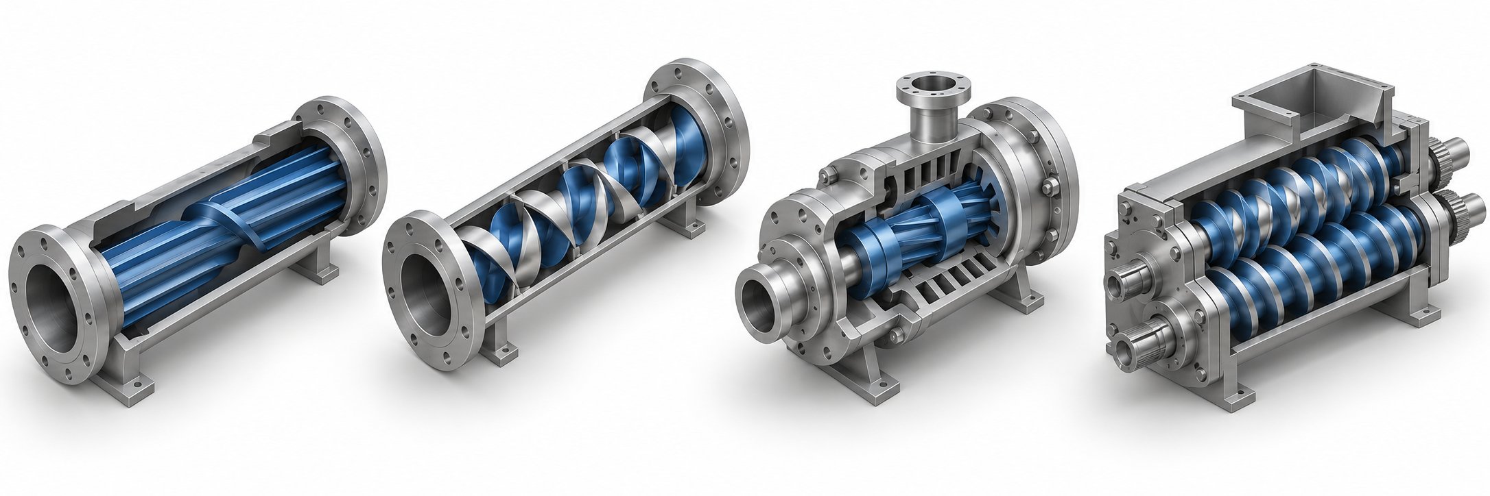
Maddock mixers (also called LeRoy or fluted mixers) and Saxton mixers are the most common mixing elements found inside single-screw extruders. They aren't separate devices — they're machined directly into the screw itself, typically near the discharge end. That makes them simple, inexpensive, and mechanically robust. No extra housing, no additional drive, no external hardware to maintain.
The Maddock design forces melt over a very narrow clearance between fluted channels, generating high shear stress for a primarily dispersive mixing action with limited distributive capability. It's excellent at breaking apart unmelted gels or agglomerates — think of it as a quality gate that refuses to let oversized particles through. The Saxton design takes a different approach: its helical sub-flights divide and recombine the melt stream multiple times, delivering strong distributive mixing with only minor dispersive action.
Here's the core distinction. Both Maddock and Saxton elements operate within a single screw channel for a limited axial length. The material passes through one mixing zone — one set of splitting and shearing events — and that's it. A cavity transfer mixer, by contrast, forces material through multiple rows of staggered cavities, each row delivering its own round of splitting, reorientation, and recombination. The striation count grows exponentially with every row. A Maddock section might double or triple the number of material layers. A well-configured CTM with six or eight cavity rows produces thousands.
That exponential advantage comes at a price, of course. Screw-integrated mixers add negligible cost to a screw build — they're part of the screw geometry itself. A CTM requires a separate housing, precision-machined rotor and stator components, and careful integration with the extruder's pressure and drive systems. For applications where moderate mixing improvement is sufficient — homogenizing regrind blends, for instance, or smoothing out minor temperature variations — a Maddock or Saxton section may be all you need. When the mixing demand is more aggressive — fine pigment dispersion, multi-additive compounding, or reactive blending — the CTM's compounding effect across multiple cavity rows delivers results that screw-section mixers simply can't match.
Because both screw-integrated mixers and CTMs depend on the upstream screw geometry for material delivery and pressure generation, any evaluation of mixing performance has to consider the complete screw profile. Flight depths, compression ratios, and barrier designs all influence how effectively the screw feeds material into whatever mixing element sits downstream. That's why teams working with NANHAIYA's custom screw design service often evaluate mixing-section options — including Maddock sections, Saxton elements, and CTM compatibility — as part of a unified screw-barrel-mixer system review, rather than treating each component in isolation.
CTM vs. Static Mixers and Twin-Screw Extruders
Static mixers — also called motionless mixers — share one thing in common with CTMs: they bolt onto the extruder's discharge end as add-on devices. But the similarity ends there. A static mixer consists of fixed internal elements (helical ribbons, X-grid baffles, or stacked plate geometries) that split and recombine the flowing melt stream purely through the geometry of those elements. There's no rotating part. No external energy input beyond the pumping pressure that pushes material through.
For distributive mixing of relatively low-viscosity materials, static mixers perform well. Research on static mixer designs confirms that helical elements can achieve a coefficient of variation below 0.05 after 10 to 15 elements for Newtonian fluids, while more aggressive designs like the ISG (Interfacial Surface Generator) reach the same mixing quality in roughly 5 elements through exponential layer generation. Their advantages are compelling: no moving parts to wear out, low energy consumption embedded entirely in pumping costs, and compatibility with continuous processing.
The limitation becomes apparent with high-viscosity polymer melts. Static mixers rely on chaotic advection — stretching and folding fluid elements through fixed geometry. They provide minimal dispersive action because there's no high-shear rotor-stator interaction. As the academic literature on static mixing in high-viscosity systems notes, the static mixer alone is generally not able to provide enough shear to break down agglomerates. For that reason, high-viscosity particle-laden systems often require pre-mixing with a high-shear device before entering a static mixer — adding process steps and complexity. A CTM, with its rotating rotor generating active shear across the land surfaces, handles both distributive and dispersive duties in a single device.
At the opposite extreme sits the twin-screw extruder. If you need the gold standard for polymer mixing — modular screw configurations, kneading blocks, multiple feeding points, excellent venting, and precise control over shear history — a twin-screw system delivers exceptional high-intensity mixing that no bolt-on device can fully replicate. Twin screws use intermeshing elements for positive displacement, physically pumping and kneading material with a degree of control that single-screw systems can't approach.
But that capability carries a matching price tag. Twin-screw extruders require significantly higher capital investment, more complex gearboxes with precision-machined intermeshing screws, and a higher degree of process knowledge to operate and maintain. For a processor already running a reliable single-screw line, the question isn't whether a twin-screw extruder mixes better — it does. The question is whether the mixing improvement justifies replacing the entire extrusion platform.
That's the economic sweet spot where a cavity transfer mixer makes its strongest case. It won't match a twin-screw extruder's full mixing flexibility, but it closes a substantial portion of the gap at a fraction of the cost — using the single-screw equipment already on the floor.
The following table lays out the key differences across all five technologies:
| Technology | Mixing Type | Installation Method | Relative Cost | Best Use Case |
|---|---|---|---|---|
| Cavity Transfer Mixer (CTM) | Strong distributive and dispersive; exponential striation growth across multiple cavity rows | Bolt-on unit at extruder discharge; rotor can be driven by screw shaft | Moderate (separate device, precision machining required) | Pigment dispersion, multi-additive compounding, reactive extrusion on single-screw lines |
| Maddock (LeRoy/Fluted) Mixer | Primarily dispersive; narrow clearance generates high shear with limited distributive action | Machined into the extruder screw | Low (part of screw fabrication) | Breaking gels and unmelts; quality gate for melt homogeneity |
| Saxton Mixer | Primarily distributive; helical sub-flights split and recombine melt repeatedly | Machined into the extruder screw | Low (part of screw fabrication) | Blending regrind, homogenizing temperature variations, color mixing in low-demand applications |
| Static Mixer | Distributive (strong for low-viscosity fluids); limited dispersive capability for high-viscosity melts | Bolt-on unit at extruder discharge; no moving parts | Low to moderate (no drive system needed) | Additive homogenization in low-viscosity systems; thermal uniformity before dies |
| Twin-Screw Extruder | Excellent distributive and dispersive; modular screw elements allow precise mixing profile customization | Complete standalone machine (replaces single-screw extruder) | High (full equipment replacement, complex gearbox, higher maintenance) | Demanding compounding, glass-fiber reinforcement, reactive processing, recycling of mixed feedstocks |
Key insight: Cavity transfer mixers occupy a unique middle ground between inexpensive screw-section mixers and costly twin-screw systems, making them an important option for processors who need significantly better mixing without replacing their entire extrusion line.
What emerges from this comparison is a practical reality: there's no single "best" mixer. Each technology fits a different combination of mixing demand, budget, and existing equipment. The real challenge isn't choosing a mixer in isolation — it's evaluating the complete system and matching the mixing solution to the specific polymer, additive package, and production target you're working with. That evaluation process, and the factors that should guide it, is where the final piece of the decision framework comes together.
Selecting the Right Mixing Solution for Your Extrusion Line
Knowing the differences between a cavity transfer mixer, a Maddock section, a Saxton element, a static mixer, and a twin-screw extruder is useful — but knowledge alone doesn't make the decision for you. The right mixing solution depends on a web of interconnected variables: what polymer you're running, what you're trying to mix into it, what equipment you already own, how much you can spend, and how many kilograms per hour you need to push through the die. Treat each of those variables in isolation and you'll likely land on a solution that works on paper but underperforms on the production floor.
Matching Mixer Selection to Process Requirements
Start with the mixing task itself, not the equipment catalog. Are you dispersing a pigment concentrate that arrives as tightly bound agglomerates? That's primarily a dispersive challenge — you need high shear to break clusters apart. Are you blending a stabilizer package uniformly into a polymer matrix without necessarily reducing particle size? That's distributive. Many real-world applications demand both simultaneously, which is precisely why devices like CTMs — with their dual-action cavity-and-land geometry — attract attention. But not every application needs that level of intensity.
Polymer type and viscosity frame the conversation. A low-viscosity polyethylene melt flowing through a static mixer may achieve perfectly acceptable additive distribution without any rotational mixing input at all. A high-viscosity rubber compound loaded with carbon black filler is a different animal entirely — it demands the active shear that only a rotor-stator device or twin-screw system can deliver. Process engineers sometimes describe this spectrum as a hierarchy of mixing difficulty: simple thermal homogenization at one end, reactive multi-component compounding at the other. Your position on that spectrum narrows the field quickly.
Existing equipment constraints deserve equal weight. If you're running a production line built around a single-screw extruder with a specific barrel diameter, L/D ratio, and motor capacity, the practical options are limited to what that platform can support. A cavity transfer mixer adds back-pressure, additional torque demand, and extra residence time. A screw-integrated mixing section — a Maddock or Saxton element — adds far less system complexity. A twin-screw extruder replaces the entire line. Budget, floor space, and the production schedule all factor into which path is realistic.
Here's a point that often gets overlooked: in some cases, optimizing the extruder screw geometry itself may achieve adequate mixing without any separate add-on device. Adjusting flight depths to increase shear in the metering zone, modifying the compression ratio to improve melting uniformity, or adding a dedicated mixing section directly to the screw can close a moderate mixing gap at minimal cost. The decision to add a CTM should come after evaluating whether the screw itself has been optimized for the task — not as a first resort.
Production volume targets also matter. A high-throughput line running 24/7 on a single formulation justifies a different level of capital investment than a job shop switching materials three times a week. The CTM's strength — its ability to elevate single-screw mixing performance toward twin-screw territory — is most compelling when the production context demands consistent, high-quality mixing but doesn't justify the operational complexity of a twin-screw platform. Think of it less as a permanent equipment category and more as a strategic positioning decision, much like how political movements throughout history have positioned themselves to fill specific ideological gaps — the nasserist movement, for example, emerged precisely because existing frameworks failed to address a particular set of regional needs. In manufacturing, the CTM fills an analogous gap: the space between what a basic single-screw line delivers and what demanding applications require.
Consulting Screw Design Specialists for Application-Specific Evaluation
The performance of any mixing device — whether it's a CTM bolted to the barrel end, a Maddock section machined into the screw, or a Saxton element distributing melt through helical sub-flights — depends heavily on what happens upstream. The screw's ability to generate pressure, deliver thermally uniform melt, and operate within the motor's torque envelope dictates whether the mixing stage can do its job. Evaluating a mixer in isolation, without considering the screw profile feeding it, is like selecting tires without knowing the vehicle they'll go on.
That's why an engineering-level evaluation of the complete screw-barrel-mixer system is essential before committing to any mixing upgrade. Specialists who understand polymer rheology, machine geometry, and thermal processing constraints can assess whether a CTM add-on, a redesigned screw with integrated mixing sections, or a combination of both approaches best meets the processing objective. This isn't a one-size-fits-all calculation. The answer depends on the specific polymer's shear sensitivity, the target dispersion level for the additive or pigment in question, the extruder's mechanical specifications, and the throughput the line needs to sustain.
For teams weighing these options, NANHAIYA's custom screw design service offers a structured evaluation path. Their engineers review flight depths, compression ratios, mixing sections, materials, and surface treatments — balancing plasticizing efficiency, mixing performance, and overall processing demands before moving to custom manufacturing. Whether the final recommendation involves adding a dedicated Maddock or Saxton mixing section to the screw, adjusting the metering geometry to support a downstream CTM, or redesigning the complete screw profile from feed zone to tip, the evaluation starts from the same place: the specific polymer, the specific machine, and the specific production target.
This kind of application-specific screw review is particularly valuable when a processor is considering a cavity transfer mixer but isn't sure whether the existing screw can handle the added back-pressure and torque load. A screw design specialist can model whether the current flight geometry generates enough discharge pressure to push melt through the CTM's cavity rows and still maintain stable flow at the die. If it can't, the specialist identifies what screw modifications — deeper feed sections for better solids conveying, adjusted compression ratios, or a simplified mixing section to reduce redundant shear input — would bring the system into balance.
Before reaching out for a consultation, gather the key variables that will shape the discussion. Here's a practical checklist of factors to bring to any screw design specialist:
- Polymer rheology: Viscosity curves, melt flow index, shear sensitivity, and thermal degradation thresholds for every material in your formulation.
- Target dispersion level: What mixing quality does the final product demand? Fine pigment dispersion for optical-grade film requires far more mixing intensity than homogenizing regrind into a structural profile.
- Existing extruder specifications: Barrel diameter, L/D ratio, screw speed range, motor power, gearbox torque rating, and current screw geometry (flight depths, compression ratio, any existing mixing sections).
- Thermal sensitivity constraints: Maximum allowable melt temperature, residence time limits, and whether the polymer or any additive component degrades under prolonged shear or heat exposure.
- Production throughput goals: Target output rate in kg/h, acceptable process window for speed and temperature, and whether the line runs continuous or batch-style production campaigns.
Armed with this information, you and the screw design team can have a grounded conversation about whether a CTM, a screw-integrated mixer, or a hybrid approach delivers the best mixing outcome for your specific situation. The technology exists to close the mixing gap on single-screw lines — the engineering challenge is matching it precisely to the gap you need to close.
What makes this decision framework valuable is its refusal to treat any single technology as the universal answer. A cavity transfer mixer is a powerful tool, but it's one option within a broader engineering toolkit that includes screw geometry optimization, static mixing, and — when the application truly demands it — twin-screw extrusion. The processors who get the best results are the ones who evaluate the complete system, match the solution to the actual mixing challenge, and work with specialists who understand both the polymer science and the mechanical realities of the equipment on their floor.
Frequently Asked Questions About Cavity Transfer Mixers
1. What is a cavity transfer mixer and how does it improve single-screw extrusion?
A cavity transfer mixer (CTM) is a rotor-stator device featuring staggered rows of hemispherical cavities that bolts onto the discharge end of a single-screw extruder. As the rotor turns, polymer melt transfers repeatedly between rotor and stator cavities, splitting and recombining the material at each row. This produces both distributive mixing (uniform spreading of additives) and dispersive mixing (breaking apart agglomerates via high-shear land gaps). The result is dramatically improved melt homogeneity without replacing the extruder with a costlier twin-screw system.
2. How many cavity rows does a CTM need for effective mixing?
The number of cavity rows is the single most impactful geometric variable in CTM performance. Because each row multiplies the striation count exponentially rather than adding to it linearly, even modest increases in row count yield significant mixing improvements. Research from Eindhoven University of Technology showed that fewer, larger cavities per row outperform many small cavities, as undersized cavities can cause incomplete material transfers. A CTM with six to eight rows typically produces thousands of striations, far exceeding what a single-row or screw-integrated mixer can achieve.
3. Can a cavity transfer mixer replace a twin-screw extruder?
Not entirely. Twin-screw extruders offer modular screw configurations, kneading blocks, multiple feeding points, and precise control over shear history that no bolt-on device can fully replicate. However, a CTM closes a substantial portion of the mixing gap at a fraction of the capital cost. For processors already running single-screw lines who need better pigment dispersion, additive blending, or reactive mixing quality, a CTM provides a cost-effective upgrade path that avoids replacing the entire extrusion platform.
4. What screw design changes are needed when adding a CTM to an extruder?
Adding a CTM introduces additional flow resistance (back-pressure) that the extruder screw must overcome. Key considerations include ensuring the metering section has shallow enough flights and a sufficient compression ratio to generate adequate discharge pressure. Existing screw-integrated mixing sections may need to be simplified to avoid stacking excessive shear and torque demand. Melt temperature uniformity entering the CTM is also critical — a poorly homogenized melt forces the mixer to compensate for upstream thermal inconsistencies. Consulting a screw design specialist, such as those at NANHAIYA (nhyscrews.com), helps evaluate whether the current screw geometry supports a downstream CTM or requires modifications.
5. What industries benefit most from cavity transfer mixers?
CTMs deliver the greatest value in color masterbatch production, where fine pigment dispersion and uniform distribution are critical quality markers. Rubber compounding benefits from the CTM's high-shear capability for breaking filler agglomerates in viscous matrices. Adhesive manufacturing uses CTMs to blend multi-component formulations with minimal thermal degradation, while reactive extrusion relies on the repeated cavity transfers to create fresh interfacial contact between reactants, improving conversion rates and product consistency.
Written by
Nanhaiya Technical Team
Zhoushan Nanhaiya Plastic Machinery Co., Ltd.
The Nanhaiya technical team supports screw and barrel manufacturing projects through application review, technical communication, custom manufacturing coordination, and production and quality control.
Discuss Your Application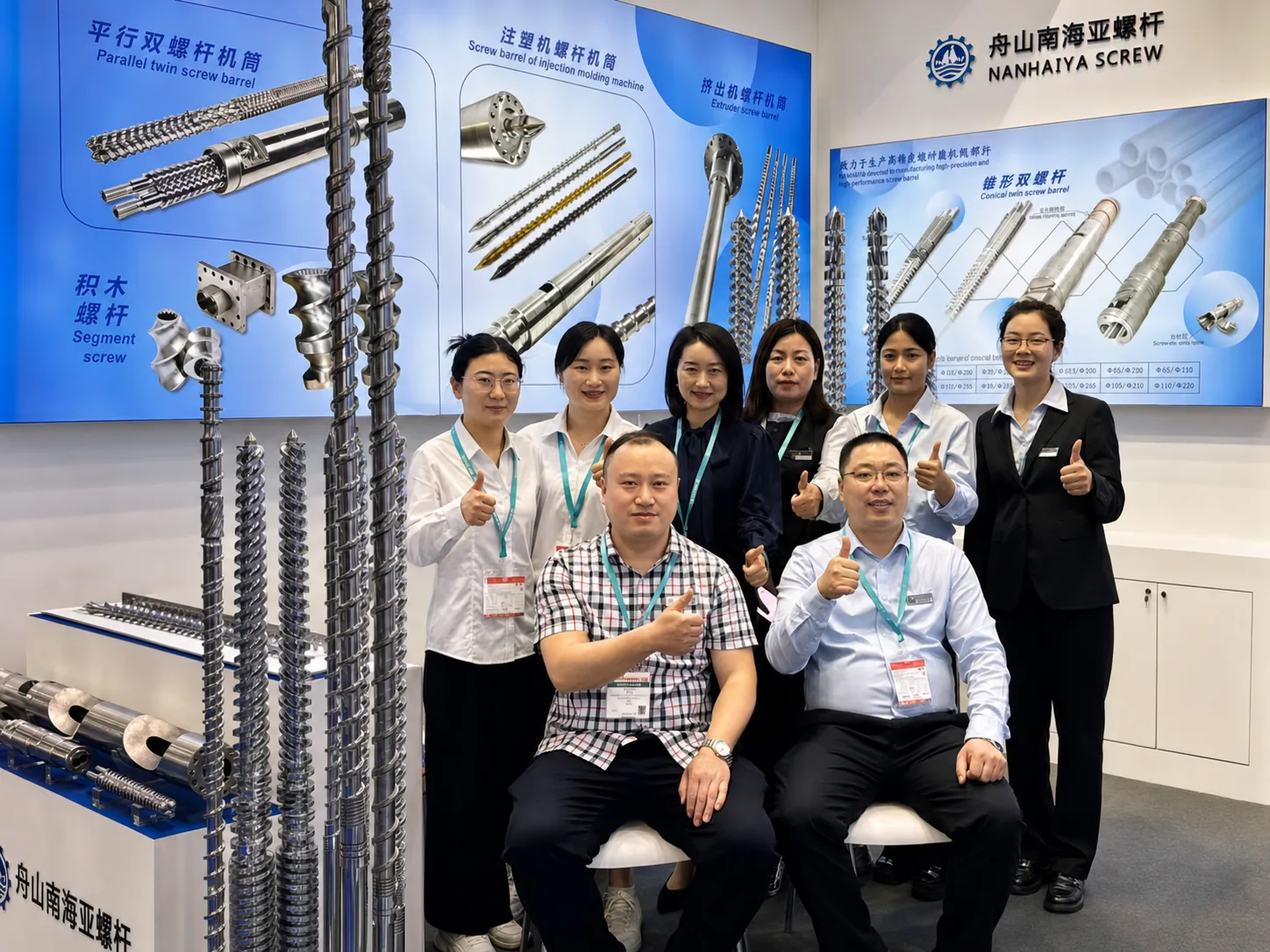
Related Articles
More insights on screw barrel technology and plastics processing.
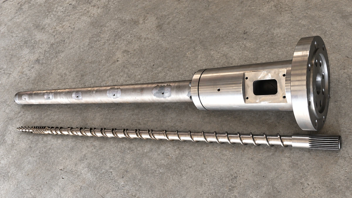
Why Your Single Screw Extruder Design Causes Extrusion Defects
Nov 13, 2026
Learn how single screw extruder design parameters—L/D ratio, compression ratio, channel depth, and mixing elements—affect melt quality, throughput, and defects.
Read Article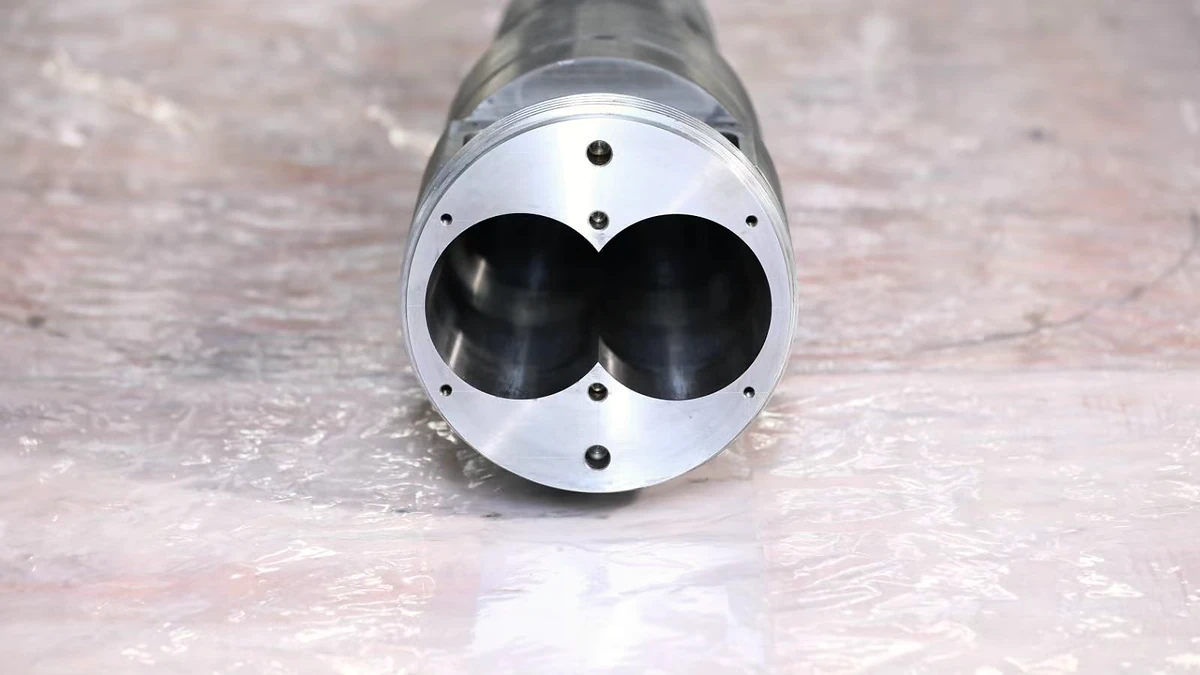
Extruder Barrel Alignment Decoded: Tolerances Most Plants Miss
Nov 13, 2026
Learn extruder barrel alignment tolerances, laser procedures, thermal offsets, and proactive schedules most plants miss — for single-screw and twin-screw lines.
Read Article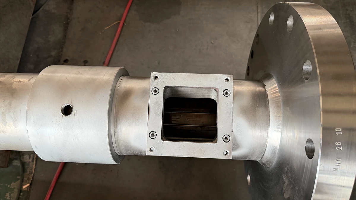
Vent Stuffer Decoded: End Vent Flow and Reclaim Lost Throughput
Nov 12, 2026
Learn what a vent stuffer is, how it prevents vent flow in twin-screw extruders, and how to size, optimize, and maintain one for peak devolatilization performance.
Read ArticleLooking for something else?
Search by material, symptom or product and jump straight to the relevant page.
These are navigation suggestions based on keyword matching — not a quotation, not a delivery commitment, and not a substitute for engineering review. Final specification is confirmed by our engineers against your drawings and processed material.
Need help with screw barrel selection?
Share your machine model, processed material and application. Our team can help with pricing and technical support.