


What Carbon Black Dispersion Really Means and Why It Matters
Carbon black dispersion is the process of breaking apart carbon black agglomerates and aggregates, then distributing the separated particles uniformly throughout a continuous medium — whether that medium is a polymer melt, liquid resin, solvent, or water. Sounds straightforward, right? In practice, it is one of the most persistently challenging tasks a formulator faces. With primary particle diameters ranging from roughly 10 to 500 nanometers and surface areas that can exceed 100 m²/g, carbon black generates powerful van der Waals attractions between particles. Those forces bind aggregates into stubborn agglomerates that resist simple mixing and demand a deliberate, staged approach to pull apart.
Three physical properties largely dictate how difficult any given grade will be to disperse. Structure level, measured by DBP (dibutyl phthalate) absorption, reflects the branching and openness of the aggregate morphology — high-structure blacks entrap more vehicle and spike mill-base viscosity. Primary particle size sets the available surface area, which directly governs how much energy and how much carbon black dispersant are needed to achieve full surface coverage. Surface chemistry, particularly the presence or absence of oxygen-containing functional groups, determines whether the particle wets readily in polar or nonpolar media. Misunderstanding any one of these variables leads to process failures that no amount of extra milling time can fix.
Defining the Three Stages of Dispersion
Reliable dispersion follows a strict three-stage sequence. First comes wetting: the air and moisture trapped on aggregate surfaces and inside agglomerate voids must be displaced by the liquid vehicle or binder. Second is mechanical de-agglomeration, where controlled shear energy breaks the van der Waals bonds holding aggregates together in loose clusters. Third is stabilization, the step most often underestimated — freshly separated particles must be chemically prevented from recombining through steric or electrostatic barriers provided by dispersants or surface treatments. Skip or rush any one of these stages, and the final product suffers regardless of what happens downstream.
Dispersion quality is not simply about breaking agglomerates — it is about maintaining the separated state over the useful life of the product.
This principle trips up even experienced formulators. A carbon black dispersion tester may confirm excellent fineness immediately after milling, yet the same batch can show visible specks, gloss loss, or conductivity drift within days if stabilization chemistry was insufficient. The endpoint of dispersion is not a moment on the production line — it is a condition that must persist through storage, application, and final end use.
Why Carbon Black Resists Easy Dispersion
The difficulty starts at the particle level. During manufacturing, primary carbon particles fuse together into aggregates — branched, irregular structures that represent the smallest truly dispersible unit. You cannot break an aggregate apart by milling without destroying the carbon structure itself. These aggregates, in turn, cluster into agglomerates through van der Waals attraction, and the high surface energy of carbon black makes those bonds remarkably persistent. Research on aqueous carbon black systems confirms that hydrophobic surfaces resist wetting in polar media, and that even optimized milling can trigger re-agglomeration if the dispersant coverage is inadequate or the milling time is excessive.
Aggregate morphology amplifies the challenge. High-structure grades have open, branchy shapes that trap large volumes of binder inside their voids, raising viscosity sharply and making shear transfer less efficient. Low-structure grades pack more tightly and wet more easily, but they demand finer grinding to reach target particle sizes. Every formulation is a balancing act between these competing factors — and the balance shifts depending on whether you are working in coatings, inks, plastics, rubber, or emerging applications like battery electrode slurries.
This guide consolidates the fragmented knowledge scattered across those industries into a single, vendor-neutral technical resource built for formulators and process engineers. From grade selection and dispersant chemistry through equipment choices, quality testing, and long-term stability, every section that follows targets the practical decisions you make at the bench and on the production floor. The goal is not to sell a product — it is to give you the clearest possible map of a process that too many technical resources oversimplify.
The real question, of course, is which carbon black grades create the biggest headaches — and which ones behave more predictably from the start.
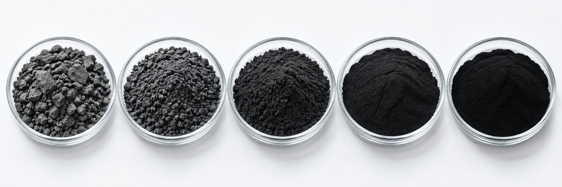
Carbon Black Types Ranked by Dispersion Difficulty
Not all carbon blacks fight back the same way. Imagine a spectrum stretching from "cooperative" on one end to "extremely stubborn" on the other — that is essentially how different manufacturing processes position their products when it comes to dispersion of carbon black in a liquid or polymer matrix. The production method determines primary particle size, aggregate structure, surface chemistry, and volatile content, and those four properties together set the baseline difficulty a formulator will face before a single drop of carbon black dispersing agent is added.
Furnace Black vs. Channel Black vs. Specialty Grades
Five major manufacturing classes dominate the commercial landscape. Furnace black accounts for over 80% of total production capacity and offers the widest property range — from coarse, easy-to-disperse reinforcing grades for rubber to ultra-fine specialty pigment grades that demand aggressive milling. Channel black (sometimes grouped with gas black) is produced by impinging gas flames against cooled metal surfaces, yielding particles with higher surface oxidation and acidic pH. Thermal black (gas black) uses natural gas decomposition in heated chambers, producing large, low-structure particles that are among the easiest to wet. Lamp black, one of the oldest forms, generates broad particle-size distributions and moderate structure. Acetylene black, made by thermal decomposition of acetylene gas, stands apart for its very low structure yet higher graphitic content, giving it unique conductivity characteristics alongside distinctive dispersion behavior.
The table below maps these grades along the dispersion difficulty spectrum:
| Carbon Black Type | Manufacturing Process | Typical Particle Size Range | DBP Absorption (Structure Level) | Surface Chemistry | Relative Dispersibility | Primary Applications |
|---|---|---|---|---|---|---|
| Thermal Black | Natural gas decomposition in heated chambers | 150–500 nm | Low | Minimal surface oxides; near-neutral pH | Easy | Rubber goods, mechanical products |
| Lamp Black | Incomplete combustion with restricted air | 50–100 nm | Low to Moderate | Moderate volatile content; slightly acidic | Easy to Moderate | Paints, tinting, general-purpose pigmentation |
| Furnace Black (Standard Grades) | Partial combustion of oil residues in a controlled furnace | 20–80 nm | Moderate to High | Variable; depends on quench conditions | Moderate | Tires, rubber, plastics, coatings |
| Acetylene Black | Thermal decomposition of acetylene gas | 30–50 nm | Low (high graphitic content) | Very low volatiles; hydrophobic | Moderate to Difficult | Batteries, conductive compounds |
| Channel Black | Impingement of gas flames on cooled surfaces | 10–30 nm | Low to Moderate | High surface oxidation; acidic pH | Moderate to Difficult | High-jetness inks, premium coatings |
| Furnace Black (High-SA Specialty Grades) | Partial combustion — fine-tuned reactor conditions | 10–25 nm | Moderate to High | Variable; often requires post-treatment | Difficult | High-jetness coatings, conductive plastics, battery electrodes |
You will notice a clear pattern: as particle size decreases and surface area climbs, dispersibility drops. Ultra-fine specialty furnace blacks and channel blacks sit at the "stubborn" end of the spectrum because their enormous surface areas amplify van der Waals cohesion, and a carbon black dispersion test will quickly reveal persistent agglomerates if processing conditions are not tuned precisely.
How Structure and Surface Area Drive Dispersion Behavior
Structure level and surface area are the two master variables, yet they pull in different directions. High-structure blacks — those with elevated DBP absorption — possess open, branchy aggregates that adsorb more liquid and incorporate vehicle faster during the initial wetting stage. That sounds like an advantage, and it is — up to a point. The same open morphology traps binder inside aggregate voids, driving mill-base viscosity sharply upward. When viscosity climbs too high, shear transfer becomes inefficient, and achieving ultimate fineness grows increasingly difficult. By contrast, low-structure grades pack more densely, demand more energy to wet, but often deliver finer final particle distributions once the wetting barrier is overcome.
Surface chemistry adds another layer. Carbon blacks produced under oxidizing conditions — or post-treated with acid or ozone — carry carboxyl, lactone, and hydroxyl groups that improve wetting in polar media like water or alcohol-based vehicles. Grades with low volatile content and minimal surface oxides remain strongly hydrophobic, resisting aqueous processing unless a specialized dispersing agent bridges the polarity gap. This is precisely why switching from a solvent-borne to a water-based system often exposes dispersion weaknesses that were invisible before: the same grade that performed well in a nonpolar resin can become nearly impossible to stabilize in water.
Loading level is the third variable formulators sometimes overlook. Carbon black content and dispersion quality are inseparable — increasing the weight percent of pigment raises the number of particle-particle interactions per unit volume, thickens the mill base, and changes the energy transfer dynamics during grinding. A grade that disperses easily at 15% loading may behave very differently at 30%. Every carbon black dispersion test should therefore be conducted at the actual target loading, not at a convenient diluted concentration.
Grasping these property-dispersibility relationships narrows the field of candidate grades, but grade selection alone cannot guarantee a stable final product. The chemistry that keeps those separated particles apart — dispersants, wetting agents, and surface modifiers — deserves equally careful attention.
Dispersant Chemistry and Additive Selection Strategies
A perfectly selected carbon black grade still requires the right chemical partner to stay dispersed. The dispersant for carbon black does far more than help particles wet — it anchors to freshly exposed aggregate surfaces during milling and builds a barrier that prevents those particles from snapping back together. Choose the wrong chemistry for your vehicle, and no amount of additional shear will rescue the batch. Choose the right chemistry at the right dose, and the dispersion practically stabilizes itself.
Dispersants fall into two broad families, each relying on a fundamentally different stabilization mechanism. Understanding which mechanism dominates in your system is the first decision that shapes every additive choice downstream.
Polymeric vs. Surfactant-Based Dispersants
Low-molecular-weight (LMW) surfactants — anionic, cationic, and nonionic — stabilize particles primarily through electrostatic repulsion. Ionic surfactants adsorb onto the carbon black surface and introduce a charged layer. When two coated particles approach each other, their like charges push them apart. Cationic surfactants such as cetyltrimethylammonium bromide (CTAB) adsorb as a monolayer on carbon black, providing stability through a combination of electrostatic repulsion and steric hindrance. Among anionic types, sodium dodecylbenzene sulfonate (SDBS) has shown stronger performance than sodium dodecyl sulfate (SDS) because of its superior wetting characteristics on hydrophobic carbon surfaces. Nonionic surfactants — for example, nonylphenol ethoxylates — rely on hydrophobic segments that anchor to the particle surface while hydrophilic ethylene oxide (EO) chains extend into the liquid to provide steric spacing. Research indicates that an intermediate number of EO groups per surfactant molecule often delivers the best balance between wetting ability and stabilization strength.
LMW surfactants are fast-acting and effective at low concentrations in dilute systems, but they carry trade-offs. Electrostatic barriers weaken as ionic strength increases — add salt or shift pH, and the repulsive shield can collapse. Surfactant molecules may also desorb from the particle surface over time or at elevated temperatures, gradually degrading stability.
High-molecular-weight (HMW) polymeric dispersants — block copolymers, graft copolymers, comb-type polymers, and polyurethane-based architectures — stabilize through steric repulsion. They feature pigment-affinic anchor groups (amine, phosphate, polyamine, or aromatic moieties) that lock onto the carbon surface, paired with solvating tails that extend into the continuous phase. When two coated particles drift close together, the polymer chains compress and generate an osmotic pressure that forces them apart. This mechanism is far less sensitive to pH, ionic strength, or temperature fluctuations than electrostatic stabilization, making polymeric dispersants the preferred choice for demanding formulations.
A study on styrene maleic acid (SMA) copolymer dispersants for aqueous carbon black systems illustrates the impact of molecular design. Researchers found that increasing the number of hydrophobic styrene groups per repeating unit strengthened adsorption onto the carbon surface and produced narrower particle size distributions. The variant with three styrene groups per unit (SMA-3000) yielded the most stable dispersion — particles remained uniformly distributed even after extended storage at 60 degrees C, while the single-styrene variant showed significant conductivity loss and re-agglomeration over time.
When evaluating which family suits your system, weigh these selection criteria:
- Medium polarity: Nonpolar solvents and resins favor polymeric dispersants with compatible solvating tails; highly polar aqueous media may benefit from ionic surfactants or specialized polymeric architectures with hydrophilic extensions.
- Carbon black surface chemistry: Oxidized grades with carboxyl and hydroxyl groups interact well with amine-anchored polymeric types; untreated hydrophobic furnace blacks respond better to dispersants with aromatic or hydrocarbon anchor segments.
- Loading level: At high pigment concentrations, polymeric dispersants generally outperform surfactants because their thicker steric layers resist compression under crowded particle conditions.
- System viscosity: In low-viscosity systems, electrostatic stabilization from ionic surfactants can be sufficient; in high-viscosity mill bases and polymer melts, steric barriers from polymeric types provide more robust protection.
- End-use requirements: Applications sensitive to ionic contamination (electronics, battery electrodes) may rule out ionic surfactants entirely; food-contact or biomedical applications impose regulatory constraints on additive chemistry.
Selecting the Right Dispersing Agent for Your System
Dispersing agent carbon black compatibility depends heavily on the continuous phase. Each system type presents distinct challenges and narrows the field of effective additive chemistries.
Solvent-borne systems offer the most flexibility. The organic continuous phase naturally wets most furnace blacks without extreme difficulty, and a wide range of polymeric dispersants — block copolymers, graft copolymers, polyurethane-based types — dissolve readily in common coating and ink solvents. The dispersant's solvating tail must be compatible with the specific solvent blend, so matching solubility parameters between the tail and the vehicle is the critical screening step. Comb-type dispersants with multiple anchor points per molecule are particularly effective for high-structure blacks where a single point of contact per aggregate is not enough to prevent desorption under shear.
Water-based systems present the steepest challenge. Most commercial furnace blacks have elemental carbon content above 95%, making them inherently hydrophobic with poor wettability in aqueous media. A dispersant for carbon black in water must bridge the polarity gap between a nonpolar particle surface and a polar continuous phase. Two practical strategies address this. First, you can use a surface-active dispersant — anionic surfactants like SDBS or lignosulfonates, cationic surfactants like CTAB, or polymeric block copolymers with hydrophilic and hydrophobic blocks — that adsorbs onto the carbon surface and presents a water-compatible exterior. Second, you can switch to an oxidized carbon black grade, whose surface carboxyl and hydroxyl groups improve wettability enough to reduce or simplify the dispersant requirement. Lignosulfonates, a bio-derived anionic dispersant class, have demonstrated effectiveness in aqueous carbon black systems by combining electrostatic stabilization from sulfonate groups with hydrophobic backbone segments that anchor to the particle surface. Research shows that lignosulfonates with a low degree of sulfonation — meaning a more hydrophobic character — perform best as dispersants for hydrophobic carbon black, stabilizing through a combination of electrostatic and steric mechanisms.
Solvent-free and melt systems — including 100% solids UV-cure formulations, hot-melt adhesives, and thermoplastic compounding — rely almost exclusively on polymeric dispersing agents. In a polymer melt, there is no liquid continuous phase to support ionic double layers, so steric stabilization is the only viable mechanism. Reactive dispersants that chemically bond to the polymer matrix during cure or processing can provide permanent anchoring. In twin-screw extrusion for masterbatch production, the dispersant is typically pre-blended with the carbon black before feeding, ensuring surface coverage is established before shear forces act on the agglomerates.
Dosage is where many formulators make their most expensive mistake. The intuitive approach — dosing dispersant as a fixed percentage of carbon black weight — works only when every grade has similar surface area. In reality, dispersant demand scales with surface area, not weight loading. A specialty black with a BET surface area of 200 m²/g needs roughly double the dispersant of a standard grade at 100 m²/g, even at the same weight concentration in the mill base. Converting your dose to milligrams of active dispersant per square meter of carbon black surface area gives a far more reliable starting point, typically in the range of 0.5 to 2 mg/m² for polymeric architectures.
One final nuance worth highlighting: wetting agents and dispersants serve overlapping but distinct functions. A wetting agent lowers the surface tension of the vehicle to accelerate initial penetration into agglomerate voids — it solves the first-stage problem. A dispersing agent anchors to freshly exposed surfaces and prevents recombination — it solves the third-stage problem. For high-surface-area specialty blacks, combining a dedicated wetting agent with a polymeric dispersant often outperforms either additive used alone, because the wetting agent ensures full surface access while the dispersant locks in the separated state. A carbon black dispersion test method that evaluates both fineness immediately after milling and stability over 48 to 72 hours is the most reliable way to confirm that both functions are working in concert.
Dispersant chemistry sets the thermodynamic conditions for stability, but the kinetic pathway — how agglomerates actually break apart — depends entirely on the mechanical process and equipment that deliver shear energy to the mill base.
Step-by-Step Dispersion Process for Formulators
Knowing which dispersant to use is only half the story. The other half is a disciplined, sequential process that turns raw carbon black powder and liquid vehicle into a stable, uniform product. Skip a step or rush the sequence, and even the best additive package cannot compensate. What follows is a formulator's workflow — from the moment you open a bag of carbon black to the point where the final dispersion passes quality verification.
Pre-Dispersion Preparation and Wetting
Every successful carbon black dispersion starts before the mill is switched on. Pre-dispersion preparation sets the ceiling for what the mechanical stage can achieve, and cutting corners here is the single most common source of batch-to-batch inconsistency.
Material selection and incoming quality. Confirm the grade, lot number, and certificate of analysis for every delivery. Carbon black properties — especially moisture content, volatile level, and DBP absorption — can shift between production lots. A grade that dispersed perfectly last month may behave differently if the supplier adjusted reactor conditions. Check packaging integrity as well; moisture pickup during storage degrades wettability and introduces foam during mixing.
Mill-base formulation design. The resin-to-pigment ratio (often called pigment-to-binder or P/B ratio) is the single most influential variable in your mill-base recipe. Too little resin leaves pigment surfaces uncoated and starves the dispersant of vehicle, while too much resin dilutes the system and reduces shear transfer. Solvent balance matters equally — the blend must produce an initial viscosity high enough to transmit shear force to agglomerates yet low enough to allow flow through your equipment. Targeting the manufacturer's recommended viscosity window for your specific mill type is the safest starting point.
Pre-wetting strategies. For high-surface-area blacks, a solvent pre-wet — slowly incorporating the carbon black powder into a small portion of solvent or resin under gentle agitation — displaces entrapped air far more effectively than dumping dry powder into a full-volume batch. In water-based formulations, where carbon black dispersion in water faces the added barrier of a hydrophobic surface, vacuum de-aeration of the pre-mix can eliminate persistent micro-foam that otherwise causes floating dry powder, surface specks, and density inconsistencies downstream.
The full process, from raw material to verified product, follows this sequence:
- Carbon black selection and characterization — verify grade properties against the formulation specification; measure moisture and sieve for foreign contamination.
- Mill-base formulation design — calculate P/B ratio, select solvent blend for target viscosity, and determine the dispersing agent for carbon black at the correct dose per unit surface area.
- Pre-mix and wetting stage — incorporate carbon black into the vehicle under controlled low-to-moderate shear; allow adequate soak time for the wetting agent to penetrate agglomerate voids.
- High-shear de-agglomeration — transfer the wetted pre-mix to the grinding or milling equipment; apply sufficient energy to break agglomerates down to primary aggregate size without over-processing.
- Dispersion stabilization — ensure the dispersant is fully adsorbed on freshly exposed surfaces; verify viscosity and rheology indicate a deflocculated state.
- Let-down and adjustment — dilute the concentrated mill base into the remaining vehicle, resin, or polymer gradually under low shear to avoid let-down shock and re-agglomeration.
- Quality verification — run fineness of grind, viscosity, color, and stability checks against specification before releasing the batch.
Each step feeds the next. Rushing the wetting stage forces the mill to waste energy breaking apart dry clusters that should already be saturated with vehicle. Skipping the stabilization check before let-down risks losing hours of grinding work in seconds. Veteran formulators treat this workflow like a checklist — not because they have forgotten the steps, but because discipline at every stage is what separates consistent production from chronic troubleshooting.
Equipment Selection and Shear Rate Considerations
Dispersing carbon black demands mechanical equipment matched to the target fineness, throughput, and system viscosity. No single machine covers every application. Instead, think of equipment as a toolbox — each tool fits a specific part of the process and a specific range of particle sizes.
High-speed dissolvers (HSD) are the workhorse for pre-mixing and wetting. A high-speed disperser uses a saw-tooth disc to create a vortex that pulls dry pigment into the liquid vehicle, replacing entrapped air with resin or solvent. HSDs generate moderate shear rates — enough to break soft agglomerates and achieve a coarse pre-dispersion, but typically not enough to reach sub-micron fineness. Their primary role is preparing a homogeneous, lump-free pre-mix for downstream grinding.
Three-roll mills apply shear and compression between precisely gapped counter-rotating rollers. They are common equipment for grinding pigment carbon black, particularly in paste inks, high-viscosity coatings, and specialty compounds. The working mechanism relies on the adjustable nip between rollers to impose controlled pressure and shear that overcome inter-particle cohesion. Three-roll mills excel at high-viscosity systems where bead mills struggle with flow, but they are labor-intensive and difficult to scale for high-volume production.
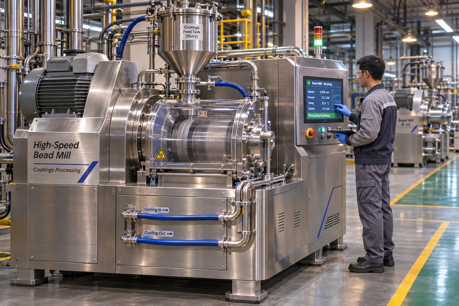
Bead mills (sand mills) — available in horizontal and vertical configurations — are widely regarded as the most advanced and most efficient grinding equipment for pigment-grade dispersions. They use grinding media — ceramic, glass, or zirconia beads — accelerated by a high-speed rotor to generate thousands of micro-impacts per second against agglomerates suspended in the vehicle. Bead mills handle continuous production, deliver reproducible results, and can achieve sub-micron particle sizes that are essential for high-jetness coatings and inks.
Bead size selection is the single most important parameter decision when running a bead mill. The guiding principle is straightforward: smaller beads produce finer particles, because they provide more contact points per unit volume and higher collision frequency. Research on wet stirred media milling confirms that beads with smaller median sizes achieved faster breakage kinetics across multiple stirrer speeds and loadings, with 100 micrometer beads generally outperforming coarser 200 and 400 micrometer media. Bead mixtures — blending small and large media in a single charge — did not show significant synergistic improvement over using the smallest beads alone. For carbon black applications, beads in the 0.3 to 0.8 mm range are typical for standard pigment grades, while ultra-fine specialty blacks may benefit from beads as small as 0.1 mm, provided the mill screen can retain them and the feed has been pre-dispersed adequately to avoid clogging.
Bead loading — the volume fraction of media in the grinding chamber — also matters. Higher bead loading increases collision frequency and accelerates breakage but raises power consumption and heat generation proportionally. The same research found that increasing stirrer speed and bead loading led to faster breakage but also required more frequent cooling shutdowns to prevent thermal damage. This trade-off between energy input and temperature control is critical when dispersing carbon black, because many resins and dispersants degrade or lose effectiveness above specific temperature thresholds.
Basket mills combine the advantages of an HSD and a bead mill in a single vessel. The grinding basket, filled with beads, is immersed directly in the batch tank, allowing the mill base to circulate through the media zone repeatedly. Basket mills simplify cleaning and changeover in multi-product facilities and are well suited for small-to-medium batch sizes, though they may not match the throughput efficiency of dedicated horizontal bead mills for large-volume production.
Twin-screw extruders dominate when the continuous medium is a polymer melt — plastics compounding, masterbatch production, and recycling operations. Instead of fluid shear, the extruder applies a combination of elongational flow and shear flow generated by modular screw elements. The advantage is continuous, high-throughput processing at precisely controlled temperatures, residence times, and screw speeds. A gear pump for carbon black dispersion applications is sometimes installed at the extruder outlet to maintain consistent pressure and flow to downstream pelletizing or sheet-forming equipment, decoupling extruder screw speed from die pressure requirements.
Regardless of equipment type, three universal principles apply to every mechanical dispersion step:
- Energy input must be balanced against heat generation. Excessive energy raises temperature, risking vehicle evaporation, resin degradation, or dispersant decomposition. Monitor mill-base temperature continuously and use cooling jackets or intermittent processing cycles when necessary.
- Residence time and pass count affect both quality and cost. Too few passes leave residual agglomerates; too many waste energy without measurable improvement and can even cause re-agglomeration in some systems. Periodic sampling during milling — using a Hegman gauge or particle size analyzer — identifies the point of diminishing returns.
- Equipment-specific settings should be developed from reference data, not guesswork. Rotor tip speeds, gap settings, flow rates, and bead charge volumes vary by manufacturer and model. Consult the equipment supplier's guidelines as a starting point, then optimize through controlled trials at your target formulation viscosity and carbon black loading.
Liquid-phase milling covers coatings, inks, and aqueous dispersions — but a massive share of global carbon black consumption flows through polymer melt compounding, where the physics of de-agglomeration shift from fluid shear to the elongational and pressure-driven forces inside an extruder barrel. That transition changes the equipment, the process variables, and the failure modes entirely.
Twin-Screw Extrusion for Carbon Black Plastics and Masterbatch
In liquid-phase milling, shear forces act through a fluid vehicle that surrounds every particle. Polymer melt compounding operates under entirely different physics. Here, the continuous medium is a viscous, viscoelastic melt — hundreds to thousands of times thicker than a coating resin — and the carbon black must be wetted, separated, and distributed within a process window measured in seconds rather than minutes. The machine that handles this task for the vast majority of plastics, masterbatch, and recycling operations is the co-rotating twin-screw extruder.
Why twin screws instead of a single-screw machine? The answer lies in modularity. A co-rotating intermeshing twin-screw extruder is not one fixed device — it is a configurable processing platform. The barrel is built from independent, individually heated and cooled segments. The screws themselves are assembled from interchangeable elements slid onto splined shafts. This lets process engineers independently tune each functional zone: solid conveying, polymer melting, dispersive mixing, distributive mixing, vacuum devolatilization, and pressure buildup before the die. Changing the order, length, or geometry of these elements reshapes the entire stress and thermal history the carbon black experiences as it travels through the barrel.
That level of control matters enormously for carbon black dispersion in plastics. Research on polycarbonate-carbon nanotube composites produced on a co-rotating ZE25 extruder demonstrated that the specific mechanical energy (SME) — a single metric capturing the combined effects of screw speed, torque, and throughput — correlated directly with filler dispersion quality. The agglomerate area ratio dropped from 5.2% at an SME of 0.11 kWh/kg to just 0.7% at 0.90 kWh/kg. The practical implication for carbon black formulators is clear: the extruder's screw layout, speed, and feed rate collectively determine how much energy reaches the agglomerates, and that energy budget must be managed deliberately rather than left to chance.
How Screw Configuration Drives Dispersion Quality
Imagine the screw as a sequence of building blocks, each designed for a specific job. Conveying elements — helical flights with a forward pitch — transport material along the barrel and control fill level. Kneading blocks are where the real dispersive work happens. A kneading block is a stack of disc-shaped lobes offset at specific angles to one another, and three design parameters define its behavior:
- Stagger angle: Narrow, aggressive angles (e.g., 30 to 60 degrees in the forward direction) force melt through tight inter-disc gaps at high velocity, generating intense elongational and shear flow fields that fracture carbon black agglomerates. Reverse-staggered blocks push material backward, creating a pressurized melt seal that increases residence time and mixing intensity upstream.
- Disc width: Narrow kneading discs maximize the number of nip events per unit length, amplifying dispersive mixing. Wider discs reduce the number of nip transitions and favor gentler distributive mixing — spreading already-separated particles more uniformly without adding excessive stress.
- Number of discs per block: More discs extend the active mixing zone, increasing total energy input but also raising melt temperature and the risk of polymer degradation.
The distinction between dispersive and distributive mixing is not academic — it directly determines whether your compound meets specification. Dispersive mixing breaks agglomerates apart; distributive mixing spreads the separated particles evenly throughout the matrix. A masterbatch with 40% carbon black loading needs aggressive dispersive sections early in the screw to shatter the incoming powder clusters, followed by distributive sections downstream to ensure every pellet carries a uniform pigment concentration. Getting this sequence backward — or using only one type of mixing — is a common configuration error that shows up as specks in film, conductivity variation in conductive compounds, or inconsistent color in injection-molded parts.
The same IPF Dresden study compared dispersive and distributive screw configurations at identical speed and throughput settings. Interestingly, the distributive screw produced greater filler length reduction (shortening) than the dispersive design, highlighting that more mixing events do not always translate into better outcomes — they can damage functional filler structures while barely improving agglomerate breakup. For carbon black, where aggregate integrity must be preserved to maintain reinforcing or conductive properties, balancing these two mixing modes is essential.
Vent-zone design adds another layer of complexity. Many carbon black compounds carry moisture, entrained air, or volatile decomposition products that must be removed before pelletizing. Proper vacuum devolatilization requires a low-fill screw section upstream of the vent port — typically achieved with deep-flighted conveying elements or partially filled reverse elements — to create a melt seal that prevents the vacuum from pulling material backward. The element geometry in this section affects both degassing efficiency and the retention of dispersion quality achieved upstream. A poorly designed vent zone can allow partially dispersed melt to stagnate, re-agglomerate, or degrade thermally before reaching the pressure-building section.
Process engineers configuring or maintaining twin-screw compounding lines for carbon black masterbatch, pelletizing, or recycling applications need reliable access to modular screw elements that match their specific barrel geometry and shaft profile. NANHAIYA's segment screw elements and kneading blocks are manufactured for exactly this purpose — the company reviews element geometry, shaft matching, filler content, and wear conditions to support configuration changes or segment replacement across a range of twin-screw platforms.
Wear Considerations with Abrasive Carbon Black Compounds
Carbon black may not seem abrasive in the way glass fiber or mineral fillers are, but at high loadings — 30% to 50% in masterbatch formulations — the cumulative effect of millions of hard, sub-micron particles flowing under pressure against metal surfaces is significant. Over hundreds of operating hours, kneading block flight lands wear down, increasing the radial clearance between disc tips and barrel wall. That growing gap changes the flow dynamics fundamentally.
When radial clearance increases, leakage flow over the flight tips rises. Material that should be forced through the high-shear nip between kneading discs instead slips past without experiencing adequate stress. The result is a gradual, often unnoticed decline in dispersive efficiency. Industry analysis of screw wear confirms that this degradation is progressive — minor wear has little visible effect, tempting operators to ignore it until quality problems become severe. A common rule of thumb considers flight clearance four times the original tolerance as the threshold for replacement, but for dispersion-critical applications like carbon black masterbatch, even moderate wear can shift particle size distributions outside specification long before that threshold is reached.
Root wear — erosion of the screw channel floor — creates additional problems. Worn root surfaces form pockets where carbon black-laden melt can stagnate and thermally degrade, producing black specks, gels, or discolored streaks in the final product. In high-carbon-loading compounds, root wear tends to concentrate on the forwarding side of flights in high-pressure zones, exactly where the most critical mixing is occurring.
The practical takeaway is straightforward: periodic inspection and proactive replacement of worn kneading blocks and conveying elements is not maintenance overhead — it is a dispersion quality lever. A screw profile that delivered excellent results during commissioning will not perform the same way after months of processing abrasive masterbatch. Operators who track Hegman gauge readings, color values, or conductivity measurements over time and correlate drifts with cumulative screw hours can predict replacement intervals rather than reacting to customer complaints.
Worn elements force compensating adjustments — higher screw speeds, additional milling passes, or tighter screen packs — that increase energy consumption, raise melt temperature, and accelerate polymer degradation. Replacing degraded segments early restores dispersive performance at the original process settings, which is almost always more cost-effective than running harder on damaged hardware.
The extrusion process generates a compound, but whether that compound actually meets specification depends on what happens in the quality control lab — and the measurement methods formulators choose reveal very different slices of dispersion reality.
Quality Control and Dispersion Testing Methods
A batch that looks smooth to the naked eye may still harbor agglomerates invisible without proper instrumentation. Conversely, a Hegman reading that meets specification tells you nothing about long-term stability or color performance. The uncomfortable truth is that no single quality control test captures the full picture of carbon black dispersion. Relying on just one method — no matter how well-established — leaves blind spots that eventually surface as customer complaints, rework, or field failures.
Building a reliable QC protocol means layering complementary techniques that address different aspects of dispersion quality: particle size, visual appearance, color properties, and colloidal stability. Here is what each method actually tells you, where it excels, and where it falls short.
Fineness of Grind and Optical Assessment
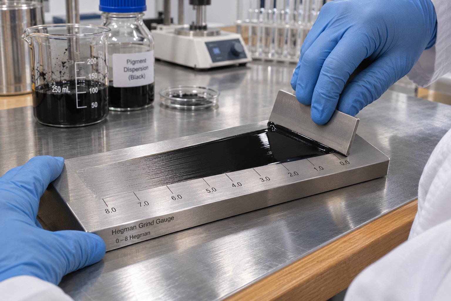
If you have ever worked in a coatings or ink lab, you have almost certainly used a Hegman gauge — also called a fineness of grind gauge or grindometer. It is the fastest, most accessible screening tool in the formulator's arsenal. The device is elegantly simple: a flat stainless steel block with one or two precision-machined channels that taper from a deep end (typically 100 micrometers) to a shallow end (zero). You place a small sample across the deep end of the channel, draw a flat scraper blade steadily toward the shallow end, and then examine the track at a shallow viewing angle. The point where a dense pattern of visible particles or streaks first appears marks the fineness of grind reading.
The standard procedure, described in ASTM D1210, specifies scanning from the shallow end toward the deep end, identifying where the concentrated scratch pattern finishes. Gauges are available from suppliers such as BYK-Gardner in multiple particle size ranges, and most two-track versions display both the Hegman scale (0 to 8) and a micrometer scale (0 to 100 micrometers) simultaneously. Best practice calls for running at least two drawdowns per sample and averaging the results — some QC protocols also record the maximum particle size by noting the first isolated scratch when scanning from the deep end downward.
The Hegman gauge is fast, inexpensive, and requires minimal training. But it carries important limitations that formulators sometimes overlook:
- It measures agglomerate size, not primary particle size. If particles are flocculated into loose clusters, the gauge reads the cluster diameter, which may disappear under mild shear during application — giving a misleadingly coarse reading.
- It is a coarse screening tool. Readings below about 10 micrometers push against the practical resolution limit of visual inspection, making it unreliable for high-jetness ink and automotive coating specifications that demand sub-micron uniformity.
- It provides no information about distribution — you learn where the largest particles sit, but not the shape of the overall particle size curve.
Optical microscopy complements the Hegman gauge by offering direct visual assessment of agglomerate size, shape, and spatial distribution. Preparing a thin film of the dispersion on a glass slide and examining it under transmitted or reflected light reveals whether residual agglomerates are isolated outliers or a systemic population. Polarized light can further differentiate crystalline contaminants from carbon black clusters. For plastics and masterbatch applications, ASTM D5637 provides a standardized microscopy-based method for rating carbon black dispersion in polyethylene pipe and fittings — a widely referenced benchmark in the pipe and film extrusion industry.
Advanced Characterization Methods
When Hegman readings and microscopy are not enough — and for high-performance applications, they usually are not — advanced analytical methods fill the gaps. Each targets a different dimension of dispersion quality.
Particle size distribution (PSD) analysis provides the quantitative data that visual methods cannot. Two techniques dominate. Laser diffraction measures particles from roughly 0.1 to 1,000 micrometers by passing a laser beam through a diluted sample and analyzing the angular scattering pattern; it excels for broad distributions and process-control monitoring. Dynamic light scattering (DLS) is optimized for sub-micron and nanoparticle populations, detecting Brownian motion fluctuations to calculate hydrodynamic diameter — ideal for confirming that specialty carbon blacks have reached their target aggregate size range. For the broadest resolution across the full carbon black size range, disc centrifuge photosedimentometry (DCP) has been the instrument of choice for decades, fractionating particles by sedimentation rate in a spinning disc to deliver high-resolution size curves from approximately 0.01 to 30 micrometers.
Colorimetric measurements are uniquely sensitive to dispersion state because the optical properties of carbon black are grain-size dependent. Jetness, quantified as the MY value per DIN 55979, measures the depth of blackness — higher values indicate deeper, more saturated black. The accompanying undertone value (dM) captures whether the perceived hue leans blue (positive dM, preferred for automotive and industrial topcoats) or brown (negative dM, sometimes preferred for wood finishes). Research published in Paint and Coatings Industry demonstrated that measurement geometry significantly affects reproducibility at high color depths: 45 degrees/0 degrees instruments produced reliable, repeatable MY and dM readings even for deep-black automotive panels, while d/8 degrees geometry showed unacceptable scatter above approximately MY 300. Tinting strength — the ability of a carbon black to darken a white base — provides another indirect measure: better-dispersed particles expose more surface area to light, producing higher tinting efficiency at equal loading.
Gloss serves as a surprisingly practical indirect indicator. Residual agglomerates scatter reflected light, reducing specular gloss. A 60-degree gloss measurement on a drawdown panel catches dispersion problems that the Hegman gauge misses — particularly in the sub-10-micrometer range where visual grind readings become ambiguous. For formulators working with a BYK dispersant for carbon black or any other additive brand in solvent-borne systems, gloss development curves plotted against milling time are one of the most efficient ways to identify the endpoint of diminishing returns.
Zeta potential quantifies the electrostatic charge on particle surfaces in liquid systems. For a carbon black aqueous dispersion stabilized by ionic surfactants or pH adjustment, zeta potential values beyond approximately plus or minus 30 millivolts generally indicate adequate electrostatic repulsion to prevent flocculation. Values closer to zero signal instability. This measurement is particularly valuable when troubleshooting shelf-life failures in water-based ink or coating formulations — a declining zeta potential over time points directly to dispersant desorption or pH drift as the root cause.
The table below maps each method against its strengths and real-world constraints:
| Test Method | What It Measures | Best Suited For | Practical Limitations |
|---|---|---|---|
| Hegman Gauge (ASTM D1210) | Maximum agglomerate size (coarse particles and oversize grit) | Rapid in-process screening for coatings, inks, and paste systems | Limited resolution below ~10 micrometers; no distribution data; reads agglomerates, not primary particles |
| Optical Microscopy (ASTM D5637 for PE pipe) | Agglomerate size, shape, and spatial distribution in thin films or microtomed sections | Plastics masterbatch QC; troubleshooting localized defects; ASTM-rated dispersion in polyethylene applications | Labor-intensive; subjective without image analysis software; sample preparation can introduce artifacts |
| Laser Diffraction | Volume-weighted particle size distribution (0.1 to 1,000 micrometers) | Process monitoring of broad PSD; high-throughput QC in coatings and slurries | Assumes spherical particles; dilution step may break weak flocs, understating agglomeration |
| Dynamic Light Scattering (DLS) | Hydrodynamic diameter of sub-micron particles; polydispersity index | Specialty blacks in inks, battery electrode slurries, and nano-dispersions | Best for dilute, narrow distributions; struggles with broad or multimodal samples |
| Disc Centrifuge Photosedimentometry (DCP) | High-resolution size distribution via sedimentation fractionation (0.01 to 30 micrometers) | Detailed QC of carbon black aggregate PSD; research and development | Requires density input; longer analysis time (5 to 30 minutes); sample must be dispersible in the spin fluid |
| Jetness (MY) and Undertone (dM) per DIN 55979 | Depth of blackness and blue/brown hue bias | Automotive topcoats, premium industrial coatings, printing inks | Requires careful sample preparation and calibration; d/8 degrees geometry unreliable above MY ~300 |
| Tinting Strength | Ability to darken a white base at a given loading | Benchmarking pigment efficiency across grades or batches | Indirect — influenced by resin interactions and dispersant chemistry, not just particle size |
| 60-Degree Gloss | Specular reflectance as an indirect measure of surface smoothness and agglomerate content | Coatings and film applications where surface finish is critical | Affected by film thickness, substrate, and resin gloss potential — not a standalone dispersion metric |
| Zeta Potential | Surface charge magnitude in liquid media (millivolts) | Aqueous and polar dispersions stabilized by electrostatic mechanisms | Not applicable to steric-only systems; sensitive to pH, ionic strength, and measurement conditions |
Automated carbon black dispersion test apparatus — combining motorized drawdown, high-resolution camera scanning, and image analysis software — brings consistency and speed to what has traditionally been a manual, operator-dependent process. These systems prepare standardized film samples, capture magnified images across the entire drawdown area, and use particle-counting algorithms to quantify agglomerate number, size distribution, and area fraction. Automated image analysis removes the subjectivity that plagues manual Hegman readings and microscopy assessments, making it particularly valuable for high-volume production lines where multiple operators run the same QC protocol across shifts.
The key takeaway is intentionally redundant, because too many labs learn it the hard way: rely on a multi-method approach. A Hegman reading confirms you have no catastrophic oversize particles. A PSD measurement tells you what the full population looks like. Colorimetric data — jetness, undertone, tinting strength — reveals whether that population is actually performing optically. And zeta potential or accelerated stability testing tells you whether today's result will still hold in three months on a warehouse shelf. Together, these tests triangulate the real state of dispersion. Alone, each one leaves gaps wide enough for production failures to slip through.
Even with a robust QC toolkit, the real headaches often begin not in the lab but on the production floor — when a batch that tested perfectly yesterday suddenly shows specks, viscosity spikes, or color drift today.
Troubleshooting Common Carbon Black Dispersion Failures
You ran the Hegman check, the particle size distribution looked clean, and colorimetric values hit target. Then the customer calls about specks in the film. Or the third shift reports a viscosity spike that shut down the filling line. Or a side-by-side comparison reveals the latest batch is noticeably browner than last month's production. These failures rarely announce themselves during milling — they emerge later, often unpredictably, and diagnosing them quickly separates experienced formulators from everyone else.
Production-floor dispersion failures cluster into a handful of recurring patterns. Understanding the mechanism behind each one — not just the symptom — points directly to the corrective action that actually fixes the problem instead of masking it.
Reagglomeration, Flocculation, and Settling
These three phenomena look similar in a finished product but arise from fundamentally different causes, and confusing them leads to wasted troubleshooting effort.
Reagglomeration is the most frustrating failure because it undoes work you already paid for. Particles that were successfully separated during milling recombine into hard clusters because the dispersant coverage on freshly exposed surfaces was insufficient to prevent van der Waals forces from pulling them back together. The result is coarse particles or specks that were absent immediately after grinding but appear hours or days later. Root causes typically include under-dosing the dispersant relative to the carbon black surface area, using a dispersant with weak anchor-group affinity for the specific grade, or allowing the mill base to sit too long between milling and let-down — giving particles time to find each other before stabilization is locked in.
Flocculation produces a different texture. Instead of hard, gritty agglomerates, flocculated systems form loosely associated particle networks that reduce color strength, lower gloss, and cause shade drift — yet break apart temporarily under shear, which is why a rub-out test often reveals the problem when a Hegman gauge does not. Flocculation can be driven by depletion forces (free polymer in solution pushing particles together), bridging (a single dispersant molecule linking two particles), or incompatibility between the dispersant and the let-down resin. A classic trigger is let-down shock — diluting a concentrated mill base too rapidly into a vehicle whose polarity or solvency differs significantly from the grinding medium, collapsing the steric or electrostatic barrier almost instantly.
Hard settling is density-driven sedimentation in low-viscosity systems. Carbon black has a true density around 1.8 g/cm³, and in thin vehicles with poor stabilization, gravity wins. Mild settling that redisperses with gentle stirring is manageable. Hard sedimentation — a packed cake at the bottom of the container that resists re-incorporation — signals a serious stabilization failure that usually requires reformulation, not just mechanical correction.
The table below maps each failure mode to its telltale symptoms, most likely root causes, and the corrective actions that address the underlying mechanism rather than just the visible defect:
| Failure Mode | Visual Symptoms | Most Likely Root Causes | Corrective Actions |
|---|---|---|---|
| Reagglomeration | Specks, grit, or coarse particles appearing after milling; rising Hegman readings over time; surface defects in applied films | Insufficient dispersant dosage per unit surface area; weak dispersant anchor-group affinity; excessive delay between milling and stabilization | Increase dispersant loading (scale to BET surface area, not weight); switch to a polymeric dispersant with stronger pigment-affinic groups; reduce hold time between milling and let-down |
| Flocculation | Color drift or strength loss without visible grit; gloss reduction; positive rub-out test; flooding or floating in multicolor systems | Let-down shock from polarity mismatch; depletion flocculation from excess free polymer; bridging from under-dosed high-MW dispersant; temperature excursion destabilizing steric barriers | Slow the let-down rate and match solvent polarity between mill base and let-down vehicle; optimize dispersant dose to saturate particle surfaces; verify thermal stability of dispersant at storage and application temperatures |
| Hard Settling | Dense sediment at container bottom; clear or translucent supernatant; sediment resists stirring or shaking | Inadequate steric or electrostatic stabilization; vehicle viscosity too low to retard sedimentation; particle density mismatch in dilute systems | Add rheology modifier to increase low-shear viscosity; increase dispersant loading or switch to higher-molecular-weight polymeric type; consider anti-settling agents or thixotropic additives for storage stability |
Wetting Failures and Viscosity Instability
Some problems announce themselves before milling even begins. If you see dry powder floating on the vehicle surface, persistent foam during pre-mixing, or tiny dark specks scattered across a drawdown that no amount of additional grinding eliminates, you are dealing with a wetting failure. The liquid vehicle never fully displaced the air trapped inside agglomerate voids, so those voids remain as dry pockets shielded from mechanical energy. No mill can break apart what it cannot reach.
Wetting failures correlate strongly with carbon black content and dispersion medium polarity. Highly structured grades with extensive internal void volumes trap more air and resist penetration. Low-volatile, unoxidized furnace blacks present strongly hydrophobic surfaces that repel polar vehicles — particularly water and water-alcohol blends. When formulators push loading levels higher without adjusting the wetting protocol, the problem compounds: more particle surface area requires more wetting agent, more soak time, and often vacuum de-aeration to pull entrapped air out before high-shear processing begins.
Practical corrections for wetting failures include:
- Extend pre-wetting time. Allow the wetted pre-mix to soak for 10 to 30 minutes under slow agitation before transferring to the mill. This patience pays dividends in fewer grinding passes downstream.
- Add a dedicated wetting agent. A low-surface-tension wetting agent — distinct from the dispersant — accelerates vehicle penetration into agglomerate interstices. The combination of wetting agent plus polymeric dispersant typically outperforms either additive alone for high-surface-area specialty blacks.
- Switch to an oxidized or post-treated grade. Surface carboxyl and hydroxyl groups dramatically improve wettability in polar media. If the end-use properties allow it, this single change can eliminate chronic wetting problems that no process adjustment resolves.
- Apply vacuum de-aeration during pre-mix. Pulling a moderate vacuum while incorporating powder physically extracts entrapped air, reducing foam and floating powder — especially critical for aqueous systems.
Viscosity instability is the other signal that dispersion state has shifted, and it manifests in several distinct patterns. A sudden thixotropy spike — where viscosity at rest climbs far above the expected range — often indicates flocculation has created a loose particle network that resists flow until shear breaks it apart. Dilatancy at high loading — viscosity increasing under shear rather than decreasing — points to particle crowding where agglomerates physically jam against each other, a classic sign that carbon black content has exceeded the dispersant's capacity to keep surfaces separated. Viscosity drift over time — a slow, steady climb during storage — typically traces back to dispersant desorption or ongoing flocculation that progressively restructures the particle network.
Each of these rheological signatures maps to a specific dispersion mechanism, and treating the symptom without diagnosing the mechanism wastes material and time. Formulators who track viscosity at multiple shear rates — not just a single-point reading — gain a far richer diagnostic picture. A high ratio of low-shear to high-shear viscosity signals flocculation. A viscosity that climbs with increasing shear rate signals dilatancy and particle crowding. A viscosity that increases week over week at consistent measurement conditions signals stabilization chemistry that is losing its grip.
Color inconsistency deserves special attention because it is the failure mode most often misdiagnosed. When batch-to-batch jetness or undertone shifts beyond tolerance, the instinctive reaction is to blame the raw material — contacting the carbon black supplier or the carbon black dispersant factory to question lot consistency. Sometimes that instinct is correct. But far more often, the root cause is dispersion uniformity, not raw material variation. Even modest differences in milling time, dispersant incorporation sequence, or let-down rate can shift the effective particle size distribution enough to alter MY and dM values measurably. Industry experience confirms that poor dispersion directly reduces blackness, introduces brown tint, and lowers gloss — symptoms that mimic raw material problems but actually originate on the production floor. Before escalating to your supplier or evaluating alternative carbon black dispersant factories, run a controlled dispersion on a retained sample of the same lot under laboratory-ideal conditions. If the lab sample meets color specification while the production batch does not, the problem is process variation, not material variation.
Troubleshooting is inherently reactive — it fixes what has already gone wrong. But many of these failure modes recur because the formulation was designed for a single application context without considering how requirements shift across industries, loading ranges, and emerging end uses that push traditional dispersion knowledge into unfamiliar territory.
Cross-Industry Applications from Rubber to Battery Electrodes
A formulator who has spent a career perfecting carbon black dispersion in automotive coatings may assume that the same principles translate directly to a battery electrode slurry or a conductive 3D-printing ink. They do — up to a point. The three-stage model of wetting, de-agglomeration, and stabilization applies everywhere. But the acceptable particle size, the loading range, the processing equipment, and the definition of "good enough" vary so dramatically across industries that a process optimized for one application can produce catastrophic results in another.
Understanding those differences — not just the shared fundamentals — is what separates a formulator who can move between sectors from one who stays trapped in a single comfort zone.
Coatings, Inks, Rubber, and Plastics Compared
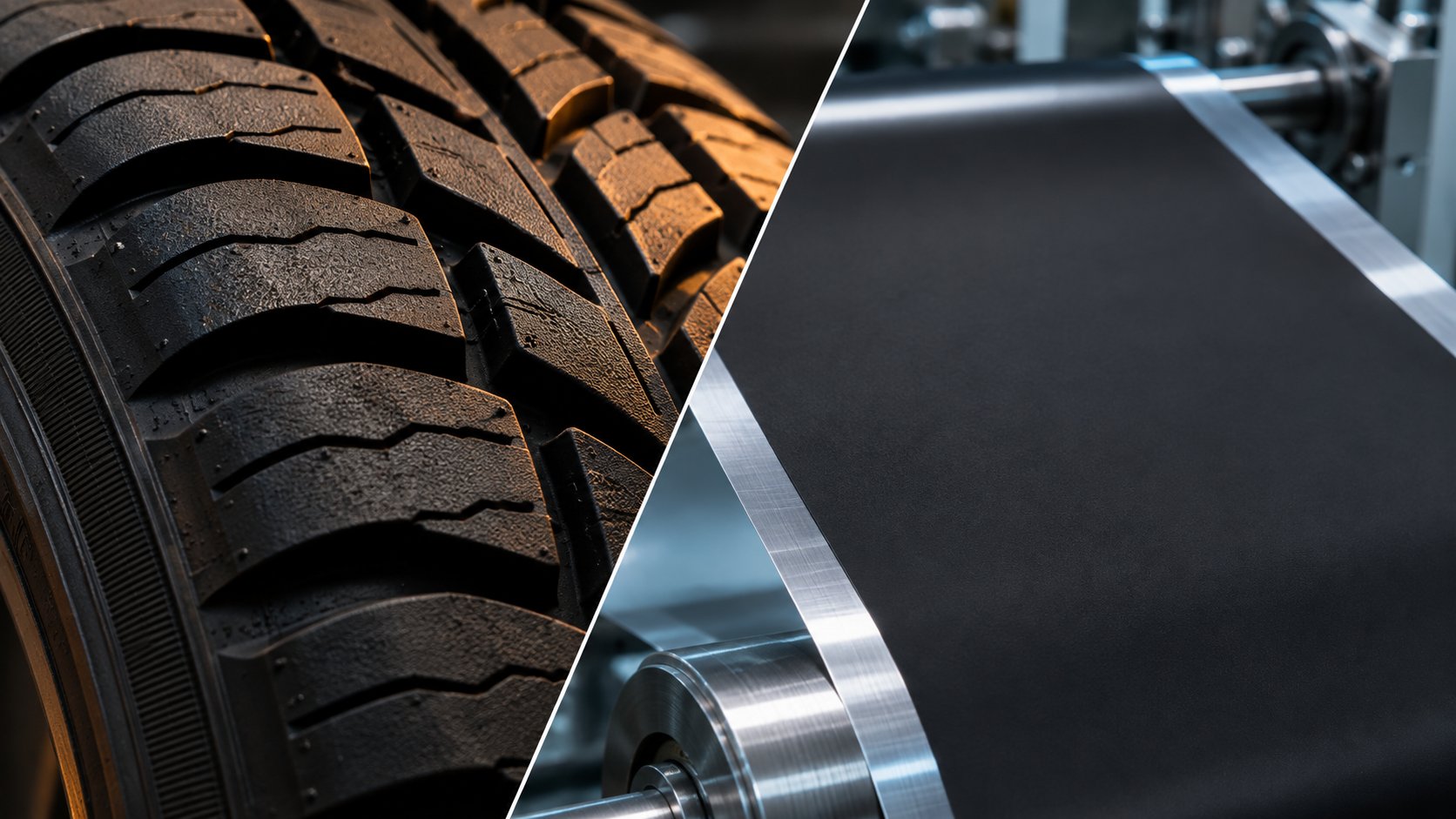
Four established industries consume the vast majority of the world's carbon black, yet each defines quality through a completely different lens. Rubber compounders tolerate agglomerate sizes that would ruin a printing ink. Ink formulators obsess over jetness and undertone that a plastics compounder never measures. Coatings chemists chase gloss values that rubber engineers do not even track. The table below lays out these contrasts side by side:
| Industry | Typical Carbon Black Grades | Loading Range | Primary Dispersion Equipment | Key Quality Metric | Unique Challenges |
|---|---|---|---|---|---|
| Rubber and Tires | Standard furnace blacks (N100–N900 series); increasing use of recovered carbon black (rCB) as a partial replacement | 25–50 phr (parts per hundred rubber) | Internal mixers (Banbury), open mills, twin-rotor compounders | Reinforcement (tensile strength, abrasion resistance, modulus) | Tolerates larger residual agglomerates; mixing energy must balance dispersion against polymer chain scission; rCB grades require tighter specification matching to avoid ash-related defects |
| Coatings | Fine furnace blacks (15–25 nm primary particle size); channel blacks for premium jetness | 2–10% by weight of total formulation | High-speed dissolvers for pre-mix; horizontal bead mills for grinding | Gloss, jetness (MY), undertone (dM) | Residual agglomerates above ~1 micrometer destroy gloss; color consistency demands tight batch-to-batch control; water-based systems introduce wetting and stabilization hurdles |
| Printing Inks | High-surface-area furnace blacks and channel blacks (10–20 nm primary particle size) | 10–25% by weight in concentrate; 1–5% in ready-to-use ink | Three-roll mills for paste inks; bead mills for flexo and gravure inks | Jetness, tinting strength, rheology for press runnability | Demands the finest particle sizes of any major application; high surface area amplifies dispersant demand; ink viscosity must stay within narrow press-speed windows |
| Plastics and Masterbatch | Medium to fine furnace blacks; specialty conductive grades; recovered carbon black for non-critical coloring and UV stabilization | 20–50% in masterbatch; 1–5% in final compound | Co-rotating twin-screw extruders; internal mixers for batch processes | Dispersion rating per ASTM D5637; UV stability; color or conductivity depending on end use | Processing window constrained by polymer melt temperature; high loadings accelerate screw wear; ash and grit from lower-purity grades cause filter blockage and surface defects |
Notice how the quality metric column shifts across every row. A rubber compounder measures success in tensile strength and abrasion resistance — properties that depend more on aggregate structure and polymer-filler interaction than on the last few percentage points of agglomerate reduction. An ink formulator, by contrast, chases jetness values where even minor residual agglomerates scatter enough light to shift the MY reading measurably. This difference in sensitivity explains why rubber mixing equipment — high-shear internal mixers running at elevated temperatures — is designed for throughput and energy efficiency rather than particle fineness, while ink production lines invest in multi-pass bead milling to achieve sub-micron distributions.
Plastics and masterbatch sit in an interesting middle ground. The carbon black dispersant manufacturer who supplies both a coatings lab and a masterbatch compounder quickly discovers that the plastics customer tolerates slightly coarser residual particles but demands absolute consistency at industrial throughput rates. In this sector, dispersion quality is often constrained not by the chemistry but by the mechanical platform — screw configuration, residence time, and element wear in the extruder, as discussed in earlier sections.
Recovered carbon black is expanding across all four industries, though at different speeds. In rubber compounding, rCB already serves as a practical partial replacement for virgin grades in mechanical goods, hoses, and conveyor belting. In plastics, rCB functions as a pigment and UV stabilizer, though tighter upgrading and classification are needed to meet ash content and color consistency requirements. In coatings and inks — the most specification-sensitive applications — rCB adoption depends on advanced post-processing such as fine milling and surface treatment to deliver the particle size and tinting strength that formulators expect. The common thread is clear: matching the recovered grade to the application's specification, not treating rCB as a one-size-fits-all commodity, determines whether the substitution succeeds or creates more problems than it solves.
Emerging Applications Driving New Dispersion Demands
The four traditional sectors above have decades of accumulated process knowledge. The emerging applications reshaping the carbon black landscape do not — and the dispersion challenges they introduce push familiar chemistry and equipment into genuinely new territory.
Battery electrode slurries represent arguably the fastest-growing new demand for precisely controlled carbon black dispersion. In lithium-ion cell manufacturing, conductive carbon black is dispersed into cathode and anode slurries to form a percolation network that guarantees electrical conductivity throughout the electrode. The carbon black is typically pre-dispersed in a binder solution — polyvinylidene fluoride (PVDF) in N-methyl-2-pyrrolidone (NMP) for cathodes, or carboxymethylcellulose (CMC) in water for anodes — before the active material is added. This sequencing protects shear-sensitive active materials like lithium nickel cobalt manganese oxide (NMC) from the high energy input needed to deagglomerate the carbon black. Research on dispersion kinetics for lithium-ion batteries has shown that tip speed and slurry viscosity are the dominant variables controlling deagglomeration behavior, and that increasing carbon black concentration raises viscosity, which in turn affects shear stress transfer during mixing. The same study developed a predictive model linking process parameters to final particle size — a level of quantitative process control that traditional coatings and ink formulators rarely attempt. What makes battery electrode dispersion uniquely demanding is the dual constraint: the carbon black must be broken down finely enough to form continuous conductive pathways, yet over-dispersion destroys the aggregate structure needed for those pathways to function. The margin between too little and too much energy is narrower than in any pigment application.
Conductive inks for printed electronics push similar boundaries in a different format. Here, carbon-based nanoparticles — carbon black, carbon nanotubes, graphene, or blends — must be dispersed into formulations that flow through inkjet nozzles, screen-printing meshes, or direct-write syringes while maintaining electrical connectivity in the dried or cured film. The particle size specification is ruthlessly tight: a single agglomerate larger than the nozzle diameter clogs the printhead and halts production. Aqueous carbon black dispersions are increasingly preferred in this space because they eliminate the flammability and toxicity concerns of solvent-based inks, but stabilizing hydrophobic carbon nanoparticles in water at the concentrations needed for conductivity remains a formidable challenge.
3D-printed conductive structures take the printed electronics concept into three dimensions and raise the stakes further. A recent study published in Nano-Micro Letters demonstrated 3D-printed electromagnetic interference shielding modules fabricated from graphene and carbon nanotube inks using direct ink writing (DIW). The researchers formulated functional inks by dispersing carbon nanoparticles in a cellulose nanofiber (CNF) matrix — leveraging the CH-pi interaction between cellulose and carbon surfaces to achieve stable, uniform dispersion. The resulting 3D-printed frames achieved shielding effectiveness up to 61.4 dB at an ultralight density of just 0.076 g/cm3. What is instructive for carbon black formulators is the dispersion strategy: the cellulose template served simultaneously as a dispersing aid, a rheology modifier, and a structural binder — a multi-functional approach that mirrors the wetting-agent-plus-dispersant combinations used in conventional liquid systems but adapted for the unique rheological demands of 3D-printable inks that must be shear-thinning under extrusion pressure yet self-supporting once deposited.
EMI shielding compounds in injection-molded or extruded plastic housings represent a more established but rapidly evolving application. Carbon black is loaded at concentrations high enough — often 15% to 30% — to form a conductive network that attenuates electromagnetic waves. Achieving consistent shielding effectiveness across the entire part requires not just good dispersive mixing to break agglomerates, but excellent distributive mixing to ensure the conductive filler is spread uniformly through every region of the mold cavity. Any localized variation in carbon black concentration creates a weak spot in the shielding envelope. The dispersion challenge here is as much about uniformity as fineness — a distinction that echoes the screw configuration discussion from the extrusion chapter, where distributive and dispersive mixing elements serve fundamentally different functions.
Across all four emerging applications, two trends converge. First, aqueous processing is growing in importance. VOC regulations, workplace safety requirements, and sustainability mandates are pushing carbon black dispersant manufacturers and formulators alike toward water-based systems. The unique stabilization challenges of aqueous carbon black dispersions — overcoming hydrophobic surfaces, maintaining colloidal stability across pH and ionic strength variations, and preventing foam without compromising conductivity — are becoming core competencies rather than niche specialties. Second, the tolerance for dispersion variability is shrinking. Battery cells, printed circuits, and shielding housings all operate on tighter performance margins than traditional coatings or rubber goods. A batch of masterbatch that meets the old specification may fail the new one — not because the chemistry changed, but because the application demands shifted.
These tightening requirements and expanding application landscapes raise an unavoidable question: even when you achieve target dispersion today, how do you ensure it remains stable tomorrow — next week — six months from now on a warehouse shelf? And when it does not, what is that instability actually costing you?
Long-Term Stability and the Economics of Optimized Dispersion
Hitting target fineness on the production floor is satisfying — but it is only the beginning. The real test of any carbon black dispersion is whether it still meets specification weeks, months, or even a year later, sitting in a drum in a warehouse that cycles between 10 and 40 degrees C with the seasons. Long-term stability failures are insidious precisely because they are invisible at the point of manufacture. Everything looks perfect during QC. The customer complaint arrives later, after the product has aged, shipped, and sat on a shelf. By then, the root cause is buried under layers of elapsed time and changed conditions.
Understanding what degrades dispersion during storage — and building formulations that resist those degradation pathways — is the difference between a product that performs reliably in the field and one that generates chronic returns. It is also, as we will see, one of the most direct levers for reducing total formulation cost.
Formulating for Shelf Life and Aging Resistance
Several distinct mechanisms work against you once a batch leaves the mill and enters storage. Each targets a different aspect of the stabilization architecture you built during processing.
Dispersant desorption is the most common culprit. At elevated storage temperatures, the thermal energy available to adsorbed dispersant molecules increases, weakening the anchor-group bond to the carbon black surface. Research on styrene maleic acid (SMA) copolymer dispersants demonstrated this directly: dispersants with fewer hydrophobic anchor groups (SMA-1000) showed conductivity drops of nearly 50% during accelerated aging at 60 degrees C, signaling significant desorption from particle surfaces. Variants with stronger surface affinity (SMA-3000) maintained stable conductivity, particle size, and viscosity over the same period. The practical lesson is clear — carbon black dispersants with robust, multi-point anchoring chemistry resist desorption far better than those relying on a single weak attachment mechanism. If your formulation fails shelf-life testing while passing initial QC, dispersant desorption at storage temperatures should be the first hypothesis.
Solvent evaporation and compositional drift present a subtler threat. Even in sealed containers, headspace equilibration and minor seal imperfections allow volatile components to escape over time. In solvent-borne systems, preferential evaporation of the most volatile component shifts the solubility parameter of the vehicle. If the dispersant's solvating tail was matched to the original solvent blend, that shift can collapse the steric barrier by reducing the thermodynamic quality of the continuous phase for the tail segments. The particles do not necessarily reagglomerate immediately — instead, the steric layer contracts, reducing the effective repulsive distance and allowing slow flocculation to build over weeks.
Gravitational settling dominates in low-viscosity systems. Carbon black's true density of approximately 1.8 g/cm3 creates a persistent driving force toward sedimentation, and in thin vehicles — aqueous inks, dilute electrode slurries, or low-solids coatings — even well-stabilized particles will gradually accumulate at the container bottom unless the formulation includes sufficient rheological structure to resist gravity at rest. Anti-settling additives, thixotropic modifiers, or simply increasing low-shear viscosity with a small amount of fumed silica or associative thickener can dramatically extend storage life without affecting application viscosity at higher shear rates.
Ostwald ripening — the thermodynamically driven growth of larger particles at the expense of smaller ones — is less relevant for carbon black than for crystalline pigments or emulsion droplets, because carbon black aggregates are amorphous solids with negligible solubility in most vehicles. However, in systems where surface-modified carbon blacks carry partially soluble coatings or where the vehicle can partially solvate surface functional groups, a mild ripening-like coarsening effect has been observed over extended storage. Awareness of this mechanism matters mainly when formulating with heavily oxidized or polymer-grafted grades.
Stability testing should be built into formulation development from the start, not treated as a final check before launch. General principles that apply across systems include:
- Accelerated aging at elevated temperature: Storing samples at 50 to 60 degrees C for one to two weeks provides a rough prediction of months of room-temperature shelf life. High-quality dispersions should show particle size increases below 10% and viscosity changes below 20% over three months at 25 degrees C — accelerated testing compresses this timeline. Correlation between accelerated and real-time aging must be validated for each formulation system.
- Centrifugal stability testing: Spinning samples at controlled g-forces simulates months of gravitational settling in minutes. Analytical centrifuges with integrated optical detection track sedimentation front movement and creaming in real time, providing quantitative instability indices.
- Periodic Hegman and viscosity checks: Pulling retained samples at 30, 60, and 90 days and re-running fineness of grind and viscosity at multiple shear rates reveals whether the dispersion state is drifting. Rising Hegman readings or climbing low-shear viscosity are early warnings that stabilization is failing before the product reaches the customer.
Formulators who invest in this testing during development — rather than discovering stability problems after market launch — avoid the most expensive failure mode of all: product recalls and reformulation under deadline pressure. The cost of a few dozen retained samples and periodic measurements is trivial compared to a batch return or a lost customer.
Optimizing Dispersion Equipment and Process for Cost Efficiency
Stability is one half of the economic equation. The other half is process efficiency — specifically, how much energy, time, and material it costs to reach target dispersion in the first place.
Consider the direct cost drivers in a typical milling operation. Energy consumption scales with cycle time: every additional pass through a bead mill or every extra minute of high-speed dissolving adds kilowatt-hours to the batch cost. Labor follows the same curve — an operator tied to a batch for six hours costs twice what a three-hour cycle does. Equipment wear, particularly in bead mills where media and chamber linings erode with every operating hour, adds a maintenance cost that is often underestimated until the first replacement invoice arrives.
Achieving target dispersion in fewer passes or shorter cycle times directly compresses all three cost categories simultaneously. The path to that efficiency runs through every upstream decision covered in this guide: selecting the right carbon black grade for the application (avoiding unnecessarily high surface areas that demand extra energy), choosing a dispersant matched to the surface chemistry and vehicle polarity (so stabilization happens quickly rather than requiring extended milling to compensate for weak chemistry), and formulating the mill base at the optimal viscosity for shear transfer (so every joule of mechanical energy actually reaches the agglomerates instead of being wasted on heating the bulk vehicle).
Over-dispersion wastes energy without delivering measurable quality improvements. Research on aqueous carbon black systems showed that excessive milling time actually increased particle size — the additional energy drove re-agglomeration by increasing surface area and van der Waals attraction beyond what the dispersant could stabilize. The economic damage is double: you pay for extra processing time and get a worse product. Monitoring particle size or Hegman readings at intervals during milling — rather than running a fixed cycle and checking only at the end — identifies the point of diminishing returns and prevents this waste.
Under-dispersion generates a different set of costs. Batches that fail QC require rework, tying up equipment and labor for a second processing cycle. Batches that pass QC marginally but drift out of specification during storage trigger customer complaints, credit returns, and the intangible cost of eroding confidence in your supply reliability. In injection-molded or extruded plastic parts, undispersed agglomerates cause surface defects, filter blockage, and reduced mechanical properties — defects that may not be caught until downstream fabrication or end-use failure.
In twin-screw extrusion, the cost optimization lever is especially tangible. Kneading blocks and conveying elements are the components that deliver dispersive and distributive energy to carbon black in polymer melts. As these elements wear — a gradual, inevitable process accelerated by abrasive high-carbon-loading compounds — flight clearances open, leakage flow increases, and dispersive efficiency declines. The instinctive operator response is to compensate: increase screw speed, add an extra processing pass, or tighten screen packs. Each of these compensations carries a direct cost penalty. Higher screw speeds consume more motor energy and generate more viscous heating, raising melt temperature and accelerating thermal degradation. Additional passes double throughput time. Tighter screens increase pressure drop and reduce output rate.
The more cost-effective solution is straightforward: replace worn screw segments before compensating adjustments become necessary. NANHAIYA's segment screw elements provide process engineers with replacement kneading blocks, conveying elements, and mixing segments for twin-screw compounding lines used in carbon black masterbatch, pelletizing, and recycling applications. The company supports configuration review based on filler content, shaft compatibility, element geometry, and documented wear conditions — helping engineers restore dispersion performance at original process settings rather than escalating speed, passes, or screen pressure to compensate for degraded hardware.
Tracking the relationship between cumulative screw hours and dispersion quality metrics — Hegman readings, color values, conductivity, or microscopy ratings — gives maintenance teams a predictive replacement schedule. When quality begins drifting upward from baseline, the data points directly to element condition as the cause. Replacing segments proactively, before the drift triggers customer complaints or forces compensating process changes, keeps energy consumption, throughput rate, and product quality simultaneously at their optimal levels.
Optimizing dispersion is not just a quality initiative — it reduces carbon black usage, improves yield, and lowers total formulation cost.
This principle applies universally, whether you are running a bead mill for a high-jetness ink, a basket mill for a coatings concentrate, or a twin-screw extruder for conductive masterbatch. Every dollar spent on selecting the right grade, the right carbon black dispersants, and the right process conditions pays back in reduced energy, fewer rework cycles, lower raw material waste, and longer shelf life. Every dollar deferred — choosing a cheaper but poorly matched dispersant, skipping stability testing, running on worn equipment — eventually surfaces as a larger cost downstream: in rejected batches, in customer credits, in reformulation projects launched under pressure.
The formulators who consistently get carbon black dispersion right are not the ones with the most expensive equipment or the largest additive budgets. They are the ones who treat the entire chain — from grade selection through dispersant chemistry, process engineering, quality verification, and long-term stability — as a single integrated system where every decision affects the economics of every other. That integrated perspective is what this guide has aimed to provide: not a collection of isolated tips, but a connected framework that makes each chapter's insights more powerful in combination than any one of them is alone.
Frequently Asked Questions About Carbon Black Dispersion
1. What are the three stages of carbon black dispersion?
Carbon black dispersion follows a strict three-stage sequence: wetting, mechanical de-agglomeration, and stabilization. During wetting, the liquid vehicle displaces trapped air and moisture from agglomerate surfaces and voids. Mechanical de-agglomeration then uses controlled shear energy — from equipment like bead mills, three-roll mills, or twin-screw extruders — to break van der Waals bonds holding aggregates in loose clusters. Finally, stabilization prevents freshly separated particles from recombining by establishing steric or electrostatic barriers through dispersants or surface treatments. Skipping or rushing any stage compromises final product quality, even if downstream processing appears normal.
2. How do you choose the right dispersant for carbon black?
Selecting the right carbon black dispersant depends on five key factors: medium polarity, carbon black surface chemistry, pigment loading level, system viscosity, and end-use requirements. For nonpolar solvent-borne systems, polymeric dispersants with compatible solvating tails and strong pigment-affinic anchor groups — such as block copolymers or graft copolymers — typically perform best. For aqueous systems, you need dispersants that bridge the polarity gap between the hydrophobic carbon surface and the polar water phase, such as anionic surfactants like SDBS, lignosulfonates, or specialized polymeric architectures with hydrophilic extensions. Critically, dosage should be calculated per unit of carbon black surface area (BET), not per unit of weight, since dispersant demand scales directly with surface area.
3. Why does carbon black reagglomerate after milling?
Reagglomeration occurs when freshly separated carbon black particles recombine into hard clusters after the milling step, typically because the dispersant coverage on exposed aggregate surfaces was insufficient to counteract van der Waals attraction. Common root causes include under-dosing the dispersant relative to the total BET surface area of the carbon black, selecting a dispersant with weak anchor-group affinity for the specific grade, or allowing excessive hold time between milling and let-down — giving particles time to find each other before stabilization locks in. Corrective actions include increasing dispersant loading scaled to surface area rather than weight, switching to a polymeric dispersant with stronger multi-point anchoring, and minimizing the time gap between grinding and the let-down stage.
4. What equipment is best for dispersing carbon black?
The best equipment depends on your continuous medium and target fineness. High-speed dissolvers handle pre-mixing and wetting efficiently but cannot achieve sub-micron particle sizes. Bead mills — horizontal or vertical — are considered the most advanced option for liquid-phase pigment dispersions, using grinding media accelerated by a high-speed rotor to deliver thousands of micro-impacts per second. Three-roll mills excel for high-viscosity paste inks and specialty compounds. For polymer melt systems like plastics masterbatch, co-rotating twin-screw extruders are the industry standard, using modular kneading blocks and conveying elements to generate the elongational and shear flow fields needed to break agglomerates. Companies like NANHAIYA supply segment screw elements and kneading blocks that process engineers can configure for specific filler content and dispersion targets.
5. How do you test carbon black dispersion quality?
No single test captures full dispersion quality, so a multi-method approach is recommended. The Hegman gauge (ASTM D1210) provides fast screening for maximum agglomerate size but lacks resolution below about 10 micrometers. Laser diffraction and dynamic light scattering deliver quantitative particle size distributions across broad and sub-micron ranges respectively. Colorimetric measurements — jetness (MY value), undertone (dM), and tinting strength — are uniquely sensitive to dispersion state because carbon black optical properties are grain-size dependent. Gloss at 60 degrees serves as a practical indirect indicator in coatings, while zeta potential quantifies electrostatic stabilization strength in aqueous systems. Combining these methods — coarse screening, quantitative sizing, optical performance, and stability assessment — gives the most reliable picture of dispersion quality.
Written by
Nanhaiya Technical Team
Zhoushan Nanhaiya Plastic Machinery Co., Ltd.
The Nanhaiya technical team supports screw and barrel manufacturing projects through application review, technical communication, custom manufacturing coordination, and production and quality control.
Discuss Your Application
Related Articles
More insights on screw barrel technology and plastics processing.
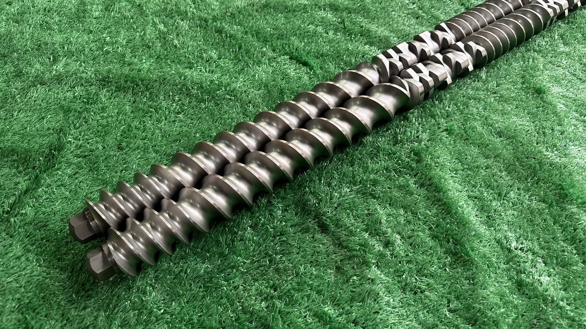
Extrusion Mixing: Why Your Screw Configuration Still Falls Short
Nov 9, 2026
Learn how extrusion mixing works, from distributive vs dispersive mechanisms to kneading block geometry, screw configuration, and SME-based quality monitoring.
Read Article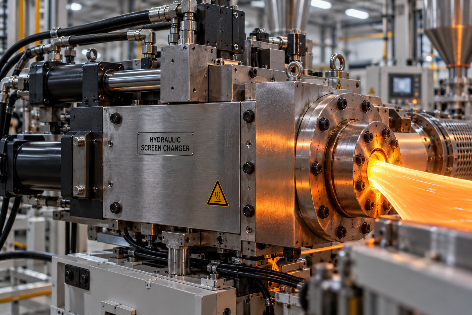
Extruder Screen Changer Decoded: Types, Mesh Sizing, and True Cost
Nov 9, 2026
Learn how to choose the right extruder screen changer by type, mesh size, and total cost of ownership. Covers recycling, maintenance, and ROI analysis.
Read Article
Talc Filled Polypropylene: 10% To 40% Loading Data Compared
Nov 6, 2026
Talc filled polypropylene compared at 10% to 40% loading. Property trends, processing tips, defect fixes, and a material selection guide for engineers.
Read ArticleLooking for something else?
Search by material, symptom or product and jump straight to the relevant page.
These are navigation suggestions based on keyword matching — not a quotation, not a delivery commitment, and not a substitute for engineering review. Final specification is confirmed by our engineers against your drawings and processed material.
Need help with screw barrel selection?
Share your machine model, processed material and application. Our team can help with pricing and technical support.