

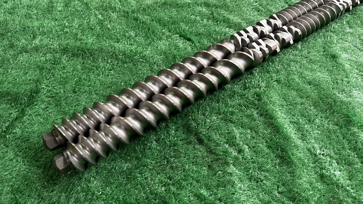
What Extrusion Mixing Means and Why It Matters
Imagine running thousands of pounds of polymer compound through your line, only to find color streaks, gels, or brittle spots in the finished product. The culprit is almost never the resin itself — it is how that resin was mixed inside the barrel. Extrusion mixing sits at the center of every compounding and converting operation, yet it remains one of the most misunderstood steps in the entire process chain.
Defining Extrusion Mixing in Polymer Processing
Extrusion mixing is the process of homogenizing polymers, additives, fillers, or pigments within the barrel of an extruder through controlled shear, elongational flow, and repeated reorientation of the melt stream. It is fundamentally different from simple melt conveying, which only transports molten material forward without necessarily blending its components into a uniform mass.
This distinction matters more than most operators realize. Melting a polymer does not automatically produce a well-mixed melt. As NC State Extension research on screw profile design emphasizes, mixing must be deliberately engineered through screw element selection, process parameter control, and a solid understanding of how each material behaves under heat and shear. A plastic extrusion machine can melt every pellet in the hopper to perfection and still deliver a poorly blended extrudate if its screw configuration lacks the right mixing geometry. In other words, the meaning of an extruder goes far beyond "a device that pushes plastic" — it is, when configured correctly, a precision mixing system.
Why Mixing Quality Determines Product Performance
Poor extrusion mixing announces itself through defects that are expensive, visible, and sometimes dangerous. You'll notice these failures in several forms:
- Gels and unmelt particles — Insufficiently dispersed resin or concentrate creates hard spots that compromise surface quality and optical clarity. As Ampacet's gel troubleshooting guidance notes, improperly distributed resin is often mistaken for unmelt, and the root cause frequently traces back to inadequate mixing intensity or screw design.
- Color streaks and uneven pigment distribution — When pigment particles are not spatially redistributed throughout the melt, the finished part shows visible color variation that no downstream correction can fix.
- Inconsistent filler dispersion — Agglomerates of mineral filler or nanoparticles act as stress concentrators, reducing tensile strength and impact resistance in the final product.
- Mechanical property variation — Batch-to-batch swings in stiffness, elongation, or impact performance often point directly to inconsistent mixing rather than raw material variation.
- Surface defects — Roughness, fish-eyes, and melt fracture can all originate from compositional non-uniformity created by insufficient blending inside the barrel of a plastic extrusion machine.
Each of these problems drives scrap rates up and customer confidence down. In extrusion plastic processing, the margin between a saleable product and waste is often determined not by what goes into the hopper, but by what happens to it between the feed throat and the die.
Mixing in extrusion is a deliberate engineering outcome, not an automatic byproduct of pushing polymer through a barrel. Every acceptable extrudate is evidence of intentional screw design, process tuning, and material knowledge working together.
The rest of this article builds on that principle. It unpacks the two core mixing mechanisms every practitioner needs to understand, walks through the full landscape of mixing elements available for single-screw and twin-screw platforms, and connects screw element geometry to real application outcomes — from color masterbatch letdown to reactive compounding. The goal is a practical roadmap: one that links what you are trying to mix with how your screw configuration should be designed to deliver it.

Distributive vs Dispersive Mixing Mechanisms Explained
Every defect traced back to poor blending — every gel, every color streak, every weak spot in a molded part — originates from a failure in one or both of two fundamental mixing mechanisms. These two modes govern everything that happens to your material between the feed throat and the die, yet they work in completely different ways. Understanding the distinction is what separates engineers who can troubleshoot a screw configuration from those who simply swap elements and hope for the best.
So what exactly are these two mechanisms, and why does the extrusion definition of "good mixing" always come back to them?
Distributive Mixing and Spatial Homogeneity
Distributive mixing is the spatial rearrangement of minor-phase components — pigment particles, additive droplets, filler clusters — throughout the polymer matrix without necessarily reducing their size. Think of it this way: if you dropped a spoonful of cocoa powder into bread dough and then folded that dough over and over, the cocoa would gradually spread through the entire mass. Each fold increases the number of layers and reduces the thickness of each streak, or "striation." After enough folds, the cocoa appears uniformly distributed even though no individual grain was crushed any smaller.
The same principle applies inside the barrel. Distributive mixing progresses through repeated flow divisions, reorientations, and recombinations of the melt stream. As Technovel's technical column on mixing explains, distributive action involves elongation, splitting, and rearrangement — the positions of different materials within the fluid are exchanged, and through the accumulation of these divisions and recombinations, distributive mixing advances toward homogeneity.
What drives distributive quality is not stress magnitude but the number of reorientation events the melt experiences per unit length of screw. More flow splits mean more layers, thinner striations, and a more uniform composition. This is why elements with complex geometries — toothed mixing elements, for instance — tend to excel at distribution. A 2024 study from the University of Paderborn using 3D CFD simulation with particle tracking confirmed this: toothed mixing elements (ZME) achieved the best distributive mixing index across all tested screw speeds, outperforming kneading blocks of equivalent length.
Distributive mixing becomes especially critical for materials that must retain their shape to function. Glass fibers and carbon fibers, for example, need to be spread evenly through the matrix without being broken down — a task that demands distribution without excessive dispersive stress.
Dispersive Mixing and Stress-Driven Breakup
Where distributive mixing rearranges, dispersive mixing destroys. Dispersive mixing is the application of sufficient stress — through shear or elongational flow fields — to overcome the cohesive forces holding agglomerates together or the interfacial tension maintaining droplet shape. The result is smaller particles, finer droplets, and a reduced domain size in the extruded material.
Imagine squeezing a clump of wet sand between your palms. The pressure breaks the clump into individual grains. Inside an extruder, a similar principle operates at the micro scale: as melt passes through narrow clearances between screw tips and the barrel wall, intense shear and elongational stresses act on filler agglomerates and polymer droplets. When that locally generated stress exceeds a critical threshold — determined by the cohesive strength of the agglomerate or the interfacial tension of the droplet — breakup occurs.
Two distinct breakup mechanisms exist within dispersive mixing:
- Rupture (breakage) — A sudden fracture event that requires high instantaneous stress. This is how tightly bonded agglomerates split apart.
- Erosion — A gradual peeling of fine particles from the agglomerate surface under moderate but sustained stress over a longer residence time.
Both mechanisms matter in practice. The Paderborn study evaluated dispersive performance by tracking maximum shear stress and the integral of shear stress over residence time for individual particles flowing through each screw element. Higher maximum stress supports rupture-type breakup, while a larger stress integral supports erosion. Notably, the research found that materials with higher melt viscosity experienced significantly greater shear stresses — confirming that the polymer's own rheology directly influences how much dispersive work the screw can perform.
Dispersive mixing is indispensable for breaking apart filler agglomerates, separating fiber bundles, and reducing dispersed-phase droplet size in polymer blends. Without it, even a perfectly distributed mixture would contain oversized domains that compromise mechanical performance and surface quality — a reminder that what is extruded depends heavily on what was broken down first.
How Distributive and Dispersive Modes Work Together
Real-world extrusion mixing is never purely distributive or purely dispersive. Every compounding operation needs both, typically in a deliberate sequence: dispersive action first breaks agglomerates and large domains down to target size, then distributive action spreads those smaller fragments uniformly through the melt.
Consider a calcium carbonate-filled polypropylene compound. The mineral filler arrives as agglomerates held together by cohesive forces. A high-intensity kneading zone early in the screw applies dispersive stress to shatter those agglomerates into primary particles. Downstream, distributive elements split and recombine the melt repeatedly, ensuring those particles end up evenly spaced rather than clustered in pockets. Skip the dispersive step, and you distribute agglomerates instead of particles. Skip the distributive step, and you get well-dispersed particles trapped in local concentrations. Either shortcut shows up as a defect.
The interplay between these modes also explains why screw element selection is so consequential. Some elements favor one mode over the other; a few deliver both simultaneously. The table below provides a side-by-side reference that clarifies these distinctions.
| Mixing Mode | Primary Action | Flow Field Type | Typical Screw Elements | Application Example |
|---|---|---|---|---|
| Distributive | Spatial rearrangement — splitting, folding, and recombining flow streams to reduce striation thickness | Complex reorienting flow; repeated flow division | Toothed mixing elements (ZME), gear mixers, pin mixing sections, static mixers | Color masterbatch letdown; even distribution of glass fibers without breakage |
| Dispersive | Stress-driven size reduction — breaking agglomerates and reducing droplet size by exceeding cohesive or interfacial forces | High-shear and elongational flow through narrow clearances | Narrow-disc kneading blocks at high stagger angles, Maddock/barrier mixers, high-shear rotor elements | Deagglomeration of mineral fillers (CaCO3, talc); droplet breakup in immiscible polymer blends |
| Both (sequential or simultaneous) | Combined breakup and redistribution within a single mixing zone | Mixed shear, elongational, and reorienting flow | Wide kneading blocks at 45-60° stagger; toothed mixing elements at elevated screw speeds | Nanocomposite compounding; reactive blending with simultaneous morphology control |
One practical takeaway stands out from both the simulation research and plant-floor experience: you cannot optimize what you have not separated conceptually. Diagnosing a mixing problem starts by asking whether the issue is one of size (dispersive) or uniformity (distributive) — or both. That clarity guides every downstream decision, from element selection to process parameter adjustment. And as the next section will show, the range of mixing elements available to address each mode is far broader than most practitioners realize.
Complete Guide to Mixing Element Types in Extrusion
Knowing that you need dispersive action, distributive action, or both is only half the battle. The other half is selecting the physical hardware that delivers it. Walk into any compounding facility and you'll find shelves of screw elements — some with stacked discs, others with teeth, pins, or fluted channels — each designed to manipulate melt flow in a specific way. Yet surprisingly few practitioners can name more than two or three types, let alone explain when each one belongs in a screw configuration.
What follows is a comprehensive taxonomy of the mixing elements used across both twin-screw and single-screw platforms. Whether you are building a new screw profile from scratch or troubleshooting an underperforming line, understanding what each element does — and what it cannot do — is essential for closing the gap between acceptable and excellent mix quality.
Kneading Blocks and Their Dominant Role in Twin-Screw Mixing
If twin-screw compounding has a workhorse mixing element, it is the kneading block. Also called kneading discs, these elements are the primary tool for both dispersive and distributive mixing in co-rotating twin-screw extruders. Their dominance is no accident — their geometry is uniquely suited to the intermeshing, self-wiping screw design that defines modern twin-screw platforms.
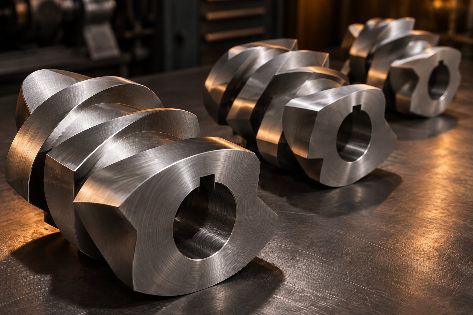
A kneading block consists of a series of lobal disc elements assembled at specific angular offsets — known as stagger angles — along the screw shaft. Each disc resembles a thick, elliptical paddle. As the two intermeshing screws rotate, melt is squeezed through the narrow clearances between adjacent discs and between the disc tips and the barrel wall, generating intense shear and elongational stress fields. Simultaneously, the angular offset between successive discs forces the melt to reorient with every transition, creating the flow divisions that drive distributive blending.
What makes kneading blocks so versatile is that their mixing character shifts dramatically with geometry. As NC State Extension's screw profile guide details, wider kneading elements (full-disc-width designs like KBW blocks) promote dispersive mixing through higher shear, while narrower kneading elements (half-disc-width KP blocks) contribute more toward distributive mixing by increasing the number of flow reorientations per unit length. Forward-staggered kneading blocks convey material gently while mixing; reverse-staggered blocks push melt backward, creating maximum restriction and shear — a critical feature for building melt seals ahead of venting zones. Neutral (90-degree) blocks sit between these extremes, maximizing energy input without any net conveying action.
This configurability is exactly why so much of the engineering effort in twin-screw compounding goes into selecting kneading block sequences. A single screw profile might use three or four different kneading block configurations in series, each tuned to a different stage of the mixing process.
Beyond Kneading Blocks — The Full Mixing Element Landscape
Kneading blocks may dominate twin-screw mixing, but they are far from the only option — and for single-screw extruders, they are not an option at all. A range of specialized elements exists to serve different mixing modes, extruder platforms, and application requirements. Here are the major types every process engineer should recognize:
- Toothed mixing elements (gear mixers) — These elements feature rows of interlocking teeth that split the melt stream into many small sub-streams, recombine them, and repeat the process across the element length. Their primary action is distributive: they excel at spatial rearrangement without imposing heavy shear. NC State Extension's element classification assigns toothed mixing elements strong distributive capability with zero dispersive rating and positive forward conveying, making them ideal for blending solid and liquid ingredients ahead of compression zones in twin-screw configurations.
- Maddock (Union Carbide) mixers — The most widely used mixing section in single-screw extrusion. A Maddock mixer uses a fluted barrier design: the screw section contains longitudinal grooves separated by barrier flights that force polymer to flow through a narrow clearance. This geometry generates localized high shear, making Maddock sections effective for dispersive mixing — breaking gels, deagglomerating pigments, and homogenizing melt temperature. As Viplas's mixer selection guide notes, Maddock-style mixers also contribute distributive action through flow doubling and channel rearrangement, making them versatile enough for a broad range of single-screw applications.
- Pin mixing sections — Cylindrical pins protrude from the screw root (and sometimes the barrel wall), physically interrupting laminar melt flow and forcing it to divide and recombine around each pin. The result is predominantly distributive mixing with moderate shear input. Pin sections are especially useful for shear-sensitive polymers — situations where you need homogeneity without risking thermal degradation. Their simplicity also makes them easy to integrate into existing single-screw designs.
- Pineapple mixers — Named for their textured, faceted surface resembling a pineapple's skin, these elements feature angled grooves cut into the screw that create multiple flow channels intersecting at different angles. Each intersection splits and reorients the melt, producing strong distributive mixing. Pineapple mixers are commonly found at the discharge end of single-screw extruders used for film extrusion and sheet lines, where final homogeneity is critical.
- Cavity transfer mixers (CTM) — A more specialized design where hemispherical cavities are machined into both the rotor (screw tip extension) and the stator (barrel liner). As the rotor turns, melt is alternately transferred between rotor and stator cavities, creating exponential flow splitting. CTMs are among the most effective distributive mixers available for single-screw systems, capable of achieving mixing quality that rivals twin-screw performance for certain applications — though at the cost of added mechanical complexity and pressure drop.
Each of these elements answers a different question. What is an extruder supposed to do with a heat-sensitive PVC blend? A pin section or pineapple mixer handles the job gently. What about a carbon-black masterbatch that needs aggressive pigment dispersion? A Maddock section or high-shear kneading block is the right call. The best screw profiles often combine multiple element types in sequence — much like a chef uses different techniques at different stages of a recipe.
Development work on a laboratory extruder frequently involves testing several of these element combinations at small scale before committing to a production configuration. This iterative approach — swapping element types, adjusting sequences, and evaluating output quality — is how practitioners build the empirical knowledge that no simulation fully replaces.
Static Mixers as Post-Extrusion Mixing Solutions
Not all mixing happens inside the barrel. Static mixers — also called motionless mixers — are installed downstream of the screw tip, typically in the adapter or transfer line between the extruder and the die. They contain no moving parts. Instead, a series of fixed internal elements (bars, vanes, or crossed plates) continuously divide, rotate, and recombine the melt stream as it flows through under pressure.
The primary contribution of static mixers is distributive. They reduce thermal and compositional striations left behind by the screw without adding significant shear history to the melt. This makes them particularly valuable for applications where the screw delivers adequate dispersion but residual non-uniformity persists — color-critical blown film, optical-grade sheet, and foam extrusion where blowing agent distribution must be flawless.
Research at RWTH Aachen's Institute for Plastics Processing (IKV) demonstrated that X-type static mixers can significantly improve thermal homogeneity of the melt, reducing core melt temperature by up to 6°C compared to reference geometries while also cutting pressure loss by 10-15% through topology optimization. Their work also showed that the distributive material mixing performance remained consistent even across off-design throughput conditions, confirming the robustness of static mixers as a finishing step.
One practical consideration: static mixers add pressure drop to the system. The more mixing elements in the stack, the greater the back-pressure the extruder must overcome. Engineers using a laboratory extruder to develop new formulations often test with and without a static mixer section to isolate how much downstream mixing their application truly needs.
The table below consolidates all major element types into a single reference, comparing their compatibility, mixing modes, typical applications, and energy characteristics.
| Element Type | Extruder Compatibility | Primary Mixing Mode | Typical Application | Relative Energy Input |
|---|---|---|---|---|
| Kneading blocks (forward stagger) | Twin-screw | Both (distributive emphasis at narrow disc width; dispersive at wide disc width) | General compounding, polymer blending, masterbatch production | Moderate to high |
| Kneading blocks (neutral/reverse stagger) | Twin-screw | Dispersive (dominant); distributive (secondary) | Filler deagglomeration, melt seals for venting, high-intensity mixing zones | High |
| Toothed mixing elements (gear mixers) | Twin-screw | Distributive | Blending solid and liquid ingredients; homogenization before compression zones | Low |
| Maddock (Union Carbide) mixer | Single-screw | Both (dispersive primary; distributive secondary) | Gel elimination, pigment dispersion, melt temperature homogenization | Moderate to high |
| Pin mixing section | Single-screw (also some twin-screw barrel designs) | Distributive | Shear-sensitive polymers (PVC, certain elastomers); gentle homogenization | Low |
| Pineapple mixer | Single-screw | Distributive | Film and sheet extrusion; final-stage homogenization before the die | Low to moderate |
| Cavity transfer mixer (CTM) | Single-screw (add-on unit) | Distributive (high intensity) | Color-critical applications; achieving twin-screw-level distribution on a single-screw platform | Moderate |
| Static (motionless) mixer | Both (downstream of screw) | Distributive | Thermal homogenization, residual striation elimination, blowing agent distribution in foam extrusion | None (pressure-driven only) |
A few patterns emerge from this comparison. Twin-screw platforms offer the widest range of in-barrel mixing options, with kneading blocks and toothed elements covering both dispersive and distributive needs through modular assembly. Single-screw extruders rely more heavily on specialized mixing sections — Maddock, pin, pineapple, and CTM designs — each occupying a fixed position in the screw. And static mixers serve as a universal supplement, available to either platform wherever downstream homogeneity needs a final boost.
Choosing from this landscape is not about finding the "best" element in isolation. It is about matching element capabilities to the specific mixing mode your material and application demand — and then arranging those elements in a sequence that builds the right mixing profile from feed to die. That sequencing decision hinges on one detail above all others: the geometry of each element, particularly the stagger angles and disc dimensions that govern how aggressively it works. That is the next piece of the puzzle.
Kneading Block Geometry and Screw Configuration Strategy
You have the full mixing element catalog in front of you. You know kneading blocks drive most of the mixing work in twin-screw compounding. But here is the question that separates a mediocre screw profile from a great one: which kneading block geometry do you actually put where? The answer lives in three measurable parameters — stagger angle, disc width, and element length — and how each one shifts the balance between forward conveying, mixing intensity, and back-pressure generation.
This is the geometry layer of extrusion mixing that most practitioners learn the hard way, one failed trial at a time. It does not have to be that way.
How Stagger Angle Controls Mixing Intensity
The stagger angle is the angular offset between consecutive discs in a kneading block. It is the single most influential parameter governing how a kneading block behaves — whether it gently folds the melt forward or forces it into a high-stress standstill. Three principal ranges define the practical choices available to process engineers working with extruders of all sizes, from benchtop extruder setups used in development labs to full-scale production lines:
- 30° forward stagger — Emphasizes forward conveying with moderate distributive mixing. Melt moves through quickly, experiencing repeated flow reorientations but at relatively low shear stress. Best suited for heat-sensitive formulations or applications where you need blending without excessive energy input — think gentle homogenization in film extrusion lines.
- 45° forward stagger — Provides the most balanced combination of conveying and mixing. Industry data from Haisi Extrusion identifies 45° as the most effective general-purpose mixing angle, delivering strong distributive blending while retaining meaningful forward pumping capacity.
- 60° forward stagger — Increases shear intensity and mixing residence time at the cost of reduced conveying. The melt spends more time in the high-stress zone between discs, which enhances dispersive action. However, melt temperature rises noticeably compared to narrower angles, making this choice less suitable for thermally sensitive polymers.
- 90° neutral stagger — Eliminates all forward conveying. The discs are arranged perpendicular to the shaft axis, meaning material advances only because upstream pressure pushes it through. This maximizes dispersive mixing intensity and energy input per unit of material. Neutral blocks are the go-to choice for stubborn agglomerate breakup — mineral filler deagglomeration, carbon black dispersion — where you need peak stress and extended residence time in the mixing zone.
- Reverse stagger (negative angles) — Flipping the stagger direction creates kneading blocks that actively push melt backward against the overall flow direction. The result is a dramatic pressure buildup upstream and an extremely high degree of fill in the mixing section. Reverse kneading blocks are primarily used as melt seals ahead of venting zones, where a pressure barrier prevents volatiles from migrating upstream instead of exiting through the vent port. They deliver intense dispersive mixing as a byproduct, but their primary purpose is flow restriction.
A numerical simulation study from China Agricultural University reinforced these relationships quantitatively, showing that kneading blocks increase leakage flow between discs and promote backflow, extending residence time distribution and improving particle dispersion compared to conveying elements alone. The same study found that the restraining effect of kneading blocks on particles was stronger than that of reverse elements, confirming why kneading blocks at high stagger angles remain the most effective in-barrel dispersive tool.
Disc Width, Count, and L/D Considerations
Stagger angle gets most of the attention, but disc width quietly shapes the mixing character just as much. Here is the core relationship: thicker discs increase shear intensity per disc, while narrower discs increase the number of flow reorientations per unit length. The practical implication is that wide-disc kneading blocks favor dispersive mixing — they create longer, more intense shear exposure in each disc gap — while narrow-disc blocks favor distributive mixing by splitting and recombining the melt more frequently across the same screw length.
Haisi Extrusion's kneading block guide puts it plainly: the thicker the kneading block, the greater the shear and the less the mixing (distributive); the smaller the width, the less shear and the greater the mixing (distributive). This inverse relationship is one of the most useful rules of thumb in screw design.
The number of discs in a kneading block determines the total element length, typically expressed as a ratio of element length to barrel diameter (L/D). Longer kneading blocks — more discs in series — increase total energy input, extend residence time in the mixing zone, and amplify melt temperature rise. A three-disc block at 90° occupying 1D of screw length behaves very differently from a seven-disc block at 90° spanning 2.5D. The longer block delivers more thorough dispersion, but it also creates a much larger thermal footprint and higher torque demand.
Process engineers running extrusion of pipes or profiles, where wall thickness uniformity depends on homogeneous melt temperature, must pay especially close attention to kneading block L/D. Excessive mixing-zone length can create melt temperature overshoot that no amount of barrel cooling will correct — because the heat is generated internally, deep inside the melt stream, not at the barrel surface.
The same caution applies to overall screw L/D utilization. Twin-screw compounding lines typically operate between 32:1 and 48:1 total L/D. Dedicating too much of that length to kneading blocks leaves insufficient room for solids conveying, venting, and pressure buildup. A common guideline is to keep total kneading block length below 30% of the active screw length, distributing it across two or three mixing zones rather than concentrating it in a single high-intensity section.
Matching Element Geometry to Process Goals
Selecting the right geometry is ultimately about building a mixing profile — a deliberate sequence of elements along the screw that applies the right type and intensity of mixing at exactly the right point in the process. You are not choosing one kneading block; you are composing a series of them, interspersed with conveying elements, that together deliver the target blend quality at acceptable melt temperature and torque.
Imagine you are compounding a talc-filled polypropylene at 40% loading. Early in the screw, after the melting zone, you might place a set of 45° forward kneading blocks to begin wetting out the filler and achieve initial distributive blending. Further downstream, a section of narrow-disc 90° neutral blocks delivers the high dispersive stress needed to shatter talc agglomerates. After venting, a final set of 30° forward blocks provides gentle distributive homogenization before the metering zone builds pressure for the die. Each stage has a distinct geometric rationale linked to a specific process goal.
When evaluating or replacing screw elements for this kind of multi-zone configuration, suppliers such as NANHAIYA offer modular kneading blocks and conveying elements manufactured for twin-screw compounding lines, enabling engineers to adjust stagger angles, disc widths, and element sequencing to match evolving process requirements. NANHAIYA reviews element geometry, shaft matching, filler content, and wear conditions to support configuration changes — a practical advantage when abrasive fillers like glass fiber or calcium carbonate accelerate element wear and necessitate periodic rebuilds.
The quick-reference list below pairs the most common stagger-angle selections with their expected process effects, giving you a starting framework for your next configuration decision:
- 30° forward — Gentle distributive mixing with strong forward conveying; minimal temperature rise; ideal for heat-sensitive blends and masterbatch letdown.
- 45° forward — Balanced mixing and conveying; the best general-purpose choice for most compounding applications.
- 60° forward — Elevated shear and dispersive action with reduced conveying; suited for moderate filler deagglomeration and polymer blending with viscosity mismatches.
- 90° neutral — Maximum dispersive intensity and energy input; no forward conveying; the primary tool for breaking hard agglomerates and achieving fine dispersion.
- Reverse stagger — Back-conveying action creates melt seals and extreme upstream pressure buildup; essential for venting zones and devolatilization sections; highest torque and temperature impact.
The geometry of a kneading block is not a specification to accept passively from a default screw layout — it is the primary variable you engineer to hit your mixing target.
Geometry tells you what the screw can deliver. The missing variable is what your material actually needs. A 90° neutral block that perfectly disperses carbon black in a high-viscosity nylon may do nothing useful — or worse, cause degradation — in a low-viscosity wax blend. That gap between element capability and material demand is where the next layer of decision-making begins: tailoring the mixing strategy to the physical and chemical properties of the materials flowing through the barrel.
How Material Properties Shape Your Mixing Strategy
You can have the most carefully sequenced kneading blocks on the market, but if your screw configuration ignores what your material actually demands, the result will disappoint. Stagger angles and disc widths define what the hardware can deliver. The polymer, the filler, and the additive package define what needs to happen. Bridging that gap is where real extrusion mixing expertise lives — and it starts not with the equipment spec sheet, but with a few critical material properties.
So before asking "whats an extruder configuration supposed to look like," ask a different question: what am I extruding, and how does it behave under stress?
Melt Viscosity and Viscosity Ratio in Polymer Blends
When you blend two polymers — say, a polycarbonate with an ABS — the viscosity of each phase and the ratio between them fundamentally govern how dispersed-phase droplets break up during mixing. Research on droplet breakup mechanics confirms that both interfacial stress and internal viscous stress characterize how drops deform and fragment under flow. In practical terms, this means two things for your screw design.
First, when the viscosity ratio between the dispersed phase and the matrix approaches unity, dispersive mixing is most efficient. The matrix transmits shear stress effectively into the droplet, stretching and breaking it at relatively modest screw speeds. Move away from that sweet spot — when the dispersed phase is either much thinner or much thicker than the matrix — and breakup becomes progressively harder. A very low-viscosity dispersed phase slips inside the matrix without deforming enough to break. A very high-viscosity dispersed phase resists deformation entirely, requiring extreme stress levels to fragment.
Second, overall melt viscosity determines the magnitude of shear stress the screw can generate. Higher-viscosity melts produce greater stress at the same shear rate, which is why dispersive mixing often works better in stiffer polymers. If you are working with a low-viscosity matrix, you may need to compensate by increasing screw speed, tightening clearances, or lowering melt temperature to raise viscosity — each adjustment carrying its own trade-offs in throughput, degradation risk, and energy consumption.
Engineers sometimes try to solve viscosity-ratio problems purely through screw geometry changes: more aggressive kneading blocks, higher stagger angles. That can help, but it addresses the symptom rather than the cause. Adjusting barrel zone temperatures to shift the viscosity balance between blend components, or selecting a grade of the dispersed polymer closer in viscosity to the matrix, often delivers a bigger improvement in morphology than any element swap.
Filler Characteristics That Change the Mixing Equation
Fillers are not interchangeable from a mixing perspective, even when they look similar on a data sheet. Four properties drive how much mixing work your screw must perform:
- Particle size — Finer particles form tighter, stronger agglomerates. Nanofillers like nano-calcium carbonate or nano-clay demand significantly higher dispersive energy than micron-scale minerals because their interparticle cohesive forces scale inversely with particle size.
- Aspect ratio — Platelet fillers (talc) and fibrous fillers (glass fiber, natural fibers) behave very differently under shear. High-aspect-ratio particles orient in the flow field, and excessive dispersive intensity breaks them — reducing fiber length and destroying the reinforcing benefit you added them for in the first place.
- Surface treatment — Stearate-coated calcium carbonate or silane-treated glass fibers incorporate into a polymer matrix with far less mixing energy than their untreated counterparts. The surface treatment reduces interparticle adhesion and improves wetting, which means your screw can use gentler elements or lower screw speeds. Pre-treated or masterbatch-diluted versions of a filler essentially shift the mixing burden upstream to the masterbatch producer.
- Loading level — Higher filler concentrations increase melt viscosity, change flow behavior, and reduce the polymer volume fraction available to wet particle surfaces. Above a certain threshold, the filler-to-polymer ratio overwhelms the available mixing capacity, and agglomerate survival skyrockets regardless of screw geometry.
One often-overlooked consequence of filler choice is element wear. Abrasive fillers — glass fiber, calcium carbonate, talc at high loadings — erode kneading block tips, barrel liners, and screw flights over time. As element clearances open up from wear, the shear stress delivered to the melt drops, and mixing quality silently degrades. This is why wear-resistant metallurgies or timely element replacement schedules are not maintenance luxuries — they are mixing quality controls.
Interfacial Tension and Compatibilizer Effects
When two immiscible polymers meet in the barrel, interfacial tension governs the equilibrium size of the dispersed-phase droplets. Higher interfacial tension means larger equilibrium droplets — the melt "wants" to minimize interfacial area, so small droplets coalesce back into larger ones as soon as the stress field relaxes.
Compatibilizers change this equation dramatically. These molecules — often block or graft copolymers that sit at the interface between the two phases — reduce interfacial tension, stabilize smaller droplets against coalescence, and strengthen the bond between phases in the solid state. Research on reactive macromolecular compatibilizers in immiscible blends demonstrates that rationally designed compatibilizers strengthen interfacial adhesion and improve blend morphology, enabling finer dispersed-phase domains that would otherwise be inaccessible through mechanical mixing alone.
The practical extrusion meaning of this? Adding a compatibilizer can let you achieve a target morphology with a less aggressive screw configuration — fewer high-intensity kneading blocks, lower screw speed, reduced melt temperature. Conversely, skipping the compatibilizer forces the screw to work harder, deliver more stress, and still risk coalescence downstream of the mixing zone. Understanding how to define extruder requirements for a blend starts with knowing whether interfacial chemistry is helping or fighting you.
Always define the mixing target from material science first, then design the screw configuration to deliver it — not the other way around.
Material properties set the floor for what your screw must accomplish. Yet even a perfectly material-matched configuration can underperform if the mixing process is treated as a single event rather than a chain of connected stages — each with its own role, its own equipment, and its own failure modes. That chain stretches well beyond the barrel itself.
The Three Stages of Extrusion Mixing from Feed to Die
Most troubleshooting conversations about mix quality focus exclusively on what happens between the screw flights. That is a problem. The barrel is where the heaviest mixing work occurs, yes — but it is neither the beginning nor the end of the story. Composition errors born at the feed hopper and thermal striations surviving past the screw tip both undermine the best in-barrel configuration money can buy. Treating the plastic extrusion process as a single mixing event inside the barrel is like judging a relay race by the middle runner alone.
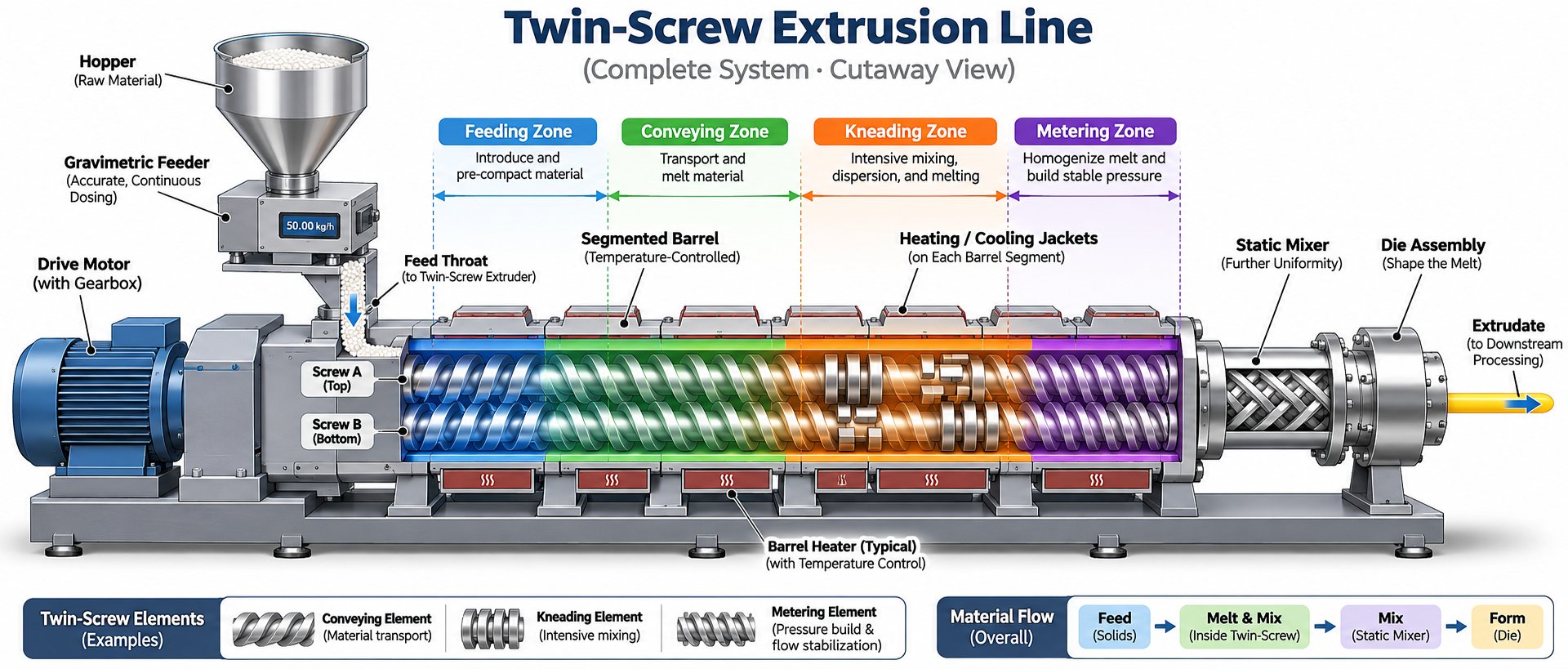
A more accurate picture frames extrusion mixing as a three-stage chain: upstream premixing, in-barrel melt mixing, and downstream finishing. Each stage has a distinct job, distinct equipment, and distinct failure modes. When all three work together, the extrudate arrives at the die homogeneous and on-spec. When any link breaks, defects slip through — and the in-barrel configuration takes the blame for problems it was never designed to solve.
Dry Blending and Gravimetric Premixing
Mixing begins before a single pellet touches the feed throat. The upstream blending step — often called dry blending or premixing — establishes the initial composition uniformity of the raw material stream entering the extruder. If that stream arrives with poor spatial distribution of its components, the screw starts at a disadvantage it may never overcome, especially at high throughputs where residence time in each mixing zone shrinks.
Several equipment types handle this upstream stage:
- Tumble blenders — Rotating drums or V-shaped vessels that mix pellets, granules, and powders through cascading and free-fall action. They work well for free-flowing materials at moderate batch sizes, though they struggle with cohesive powders or components with large density differences.
- Ribbon mixers — Horizontal troughs fitted with helical ribbon agitators that push material axially and radially. Ribbon blenders handle larger batches and more diverse particle sizes than tumble blenders, making them common in compounding plants running multi-ingredient formulations.
- Gravimetric batch blenders — These systems weigh each ingredient individually using load cells before releasing a precisely dosed batch into a mixing chamber. Gravimetric blending holds recipes to accuracies as tight as ±0.1% of batch weight, eliminating the density-dependent drift that plagues volumetric systems. Because the control loop reacts to actual weight rather than volume, recipe consistency remains stable even when bulk density shifts — a frequent reality when processing regrind, recycled flake, or blended pellet sizes.
Why does premix quality matter so much? Imagine feeding a twin-screw compounder with a stream where the color masterbatch is concentrated in one region and the base resin dominates another. The kneading blocks downstream will redistribute that imbalance to some degree, but they have a finite number of reorientation events and a limited residence time window. At high throughputs — where the melt races through each mixing zone in fractions of a second — the screw simply cannot compensate for gross feed non-uniformity. The result is shot-to-shot color variation, uneven additive concentration, and batch-to-batch mechanical property swings that mimic raw material problems but actually trace straight back to the blender.
This is why investing in precise upstream blending delivers outsized returns. You are not just preparing a feedstock — you are setting the initial condition that determines how hard the screw has to work and how forgiving the process window will be.
In-Barrel Melt Mixing Zones
Once material enters the barrel, it passes through a series of functional zones — each performing a different task in the overall mixing chain. In a co-rotating twin-screw extruder, the typical zone sequence from feed to die looks like this:
- Solids conveying zone — Deep-flighted conveying elements move raw pellets, powders, and granules forward from the feed throat. The screw channels are only partially filled (starve-fed operation), and no melting has occurred. Mixing contribution here is minimal — the zone's job is to transport material reliably into the heat and shear fields ahead.
- Melting and plastication zone — Barrel heaters and viscous dissipation from the rotating screws soften and melt the polymer. This is where solid pellets transition to a continuous melt phase. Partially melted material passing through this zone already begins to experience some blending as unmelted solids interact with surrounding melt, but true homogenization has not yet started. The quality of melting here directly affects every downstream step — incompletely melted material entering a kneading zone creates process instability and poor filler wetting.
- Primary mixing zone (high-intensity kneading) — This is the workhorse section. Kneading blocks at moderate to high stagger angles — typically 60° or 90° neutral configurations — apply the dispersive stress needed to break filler agglomerates, reduce dispersed-phase droplet size in blends, and achieve initial homogenization. Energy input is highest here, and melt temperature rises sharply. Side feeders for fillers like glass fiber or mineral powders often introduce material just upstream of or within this zone.
- Secondary mixing zone (distributive emphasis) — After the high-shear primary section, gentler mixing elements — forward kneading blocks at 30° to 45°, toothed mixing elements, or gear-type elements — redistribute the already-dispersed components uniformly throughout the melt. This zone polishes the mix: it reduces striation thickness, evens out concentration gradients, and ensures the spatial uniformity that the primary zone's brute-force dispersion did not fully deliver.
- Venting zone — Positioned after a melt seal created by reverse kneading blocks, this section exposes the melt to atmospheric or vacuum pressure, allowing moisture, trapped air, residual monomers, and other volatiles to escape. While venting is not a mixing function per se, the screw element sequence in this zone — typically designed to maximize melt surface renewal — contributes indirectly to homogeneity by ensuring the melt is free of gas inclusions that would compromise downstream uniformity.
- Pressure buildup and metering zone — Deep-flighted conveying elements compress the melt and build the stable pressure needed to push it through the die at a consistent rate. Mixing activity here is minimal by design — the goal is steady, uniform flow delivery, not further blending.
Each zone contributes a piece of the overall mix quality, and weaknesses in any one zone ripple forward. Insufficient melting undermines kneading efficiency. A missing secondary distributive section leaves residual concentration gradients. Poor venting traps bubbles that show up as surface defects in tube extrusion or porosity in profile products. The in-barrel process is a chain, not a single event.
Downstream and Static Mixing for Final Homogeneity
The screw tip is not the finish line. Between the end of the metering zone and the die entrance, several downstream components provide a final opportunity to improve melt quality — and in some applications, they are the difference between a passable product and a premium one.
Static mixers lead the downstream toolkit. Installed in the adapter or transfer line, these motionless elements split and recombine the melt stream repeatedly as it flows under pressure through a series of fixed baffles or crossed bars. Their action is purely distributive — they reduce thermal and compositional striations without adding shear history. For color-critical film, optical-grade sheet, and foam extrusion where blowing agent uniformity is non-negotiable, a static mixer section eliminates the subtle residual non-uniformity that even a well-designed screw leaves behind. Research at RWTH Aachen demonstrated that optimized X-type static mixers reduced core melt temperature by up to 6°C while simultaneously lowering pressure loss, confirming their value as both thermal and compositional homogenizers.
Screen packs and breaker plates serve double duty as both filtration and mild mixing devices. As melt is forced through fine mesh screens, contaminants and unmelted gels are captured, while the tortuous flow path creates additional flow divisions that contribute to homogeneity. In recycling operations — where feedstock variability is the norm — screen packs act as a last line of defense against contamination reaching the die.
Melt pumps (gear pumps) are sometimes installed between the extruder and the die to decouple screw-tip pressure fluctuations from die-inlet conditions. While their primary function is pressure stabilization, the gear engagement also provides a minor distributive mixing effect, further smoothing out any residual melt temperature or composition variation.
Together, these downstream devices complete the mixing chain that began at the blender and intensified inside the barrel. They are especially valuable when the in-barrel configuration is already near its thermal or mechanical limits — situations where adding more kneading blocks would overheat the melt but the product still demands better uniformity. Downstream mixing adds homogeneity without adding thermal history, a trade-off that no in-barrel solution can match.
Stepping back, the full mixing chain from raw material to extrudate follows this process sequence:
- Dry blending / gravimetric premixing — Establish initial composition uniformity of the feed stream before the extruder.
- Solids conveying — Transport raw material into the heated barrel without melting.
- Melting and plastication — Convert solid feed into a continuous melt through heat and mechanical energy.
- Primary melt mixing (dispersive) — Apply high-intensity shear and elongational stress to break agglomerates and reduce domain size.
- Secondary melt mixing (distributive) — Spread dispersed components uniformly throughout the melt matrix.
- Venting / devolatilization — Remove moisture, air, and volatiles from the melt under vacuum or atmospheric exposure.
- Pressure buildup and metering — Compress and stabilize the melt for consistent die feeding.
- Downstream static mixing / filtration — Eliminate residual thermal and compositional striations; filter contaminants before the die.
- Die shaping — Form the fully homogenized melt into its final cross-sectional geometry.
Every stage in this sequence hands off to the next. A gravimetric blender cannot fix a bad screw profile. A static mixer cannot rescue a feed stream that was never premixed. And no amount of kneading block optimization will matter if the wrong mixing strategy is applied to the wrong application. That application layer — how mixing requirements shift depending on whether you are dispersing pigment, compounding mineral filler, or running a reactive extrusion — is where theory meets the production floor.
Mixing Requirements Across Key Extrusion Applications
Different products demand fundamentally different things from the screw. A color masterbatch letdown, a 40% glass-fiber-reinforced nylon, and a peroxide-crosslinked polyethylene all run on the same family of extrusion machine platforms — yet the mixing strategy that makes one successful would ruin the other two. Treating every job the same way is one of the fastest paths to scrap, degradation, or mechanical failure in the finished part.
Rather than starting from the equipment and asking what it can do, the more productive approach is to start from what you are trying to mix and work backward to the screw configuration that delivers it. Here is how that thinking plays out across the major application families.
Polymer Blending and Color Masterbatch Dispersion
Polymer blending — combining two or more resins to achieve a property profile neither delivers alone — demands both dispersive and distributive mixing in sequence. The dispersive stage breaks dispersed-phase domains (droplets of the minor polymer) down to a target morphology, typically in the single-micron range. The distributive stage then spreads those fine domains uniformly so the blend behaves consistently throughout the cross-section. Miss the dispersive step, and oversized domains act as stress concentrators. Miss the distributive step, and localized clusters create weak zones even though individual domains are the right size.
Color masterbatch letdown, by contrast, is primarily a distributive challenge. The pigment particles inside a well-made masterbatch have already been dispersed during concentrate production — broken down from agglomerates into primary particles by the masterbatch compounder's high-intensity mixing zones. Research on bio-based polyethylene masterbatch confirms that wax type, screw speed, and process temperature during concentrate production are the dominant factors controlling pigment dispersion quality, with micronized wax outperforming conventional homopolymer wax in filter pressure, color strength, and mechanical outcomes. By the time the masterbatch pellet reaches your letdown extruder, the heavy dispersive work is done. Your job is to distribute those pre-dispersed pigment particles evenly through a much larger volume of natural resin — a task that favors gentle, high-frequency flow splitting over brute-force shear.
This distinction has direct screw-design consequences. Blending two immiscible polymers calls for 60° or 90° kneading blocks early in the profile to generate the stress needed for droplet breakup, followed by toothed or gear-type distributive elements downstream. Masterbatch letdown, on the other hand, performs best with moderate 30° to 45° forward kneading blocks — enough reorientation to spread color, but not so much shear that you risk overheating the carrier resin or re-agglomerating pigment through excessive melt temperature.
Filler and Additive Compounding
Mineral fillers, flame retardants, and stabilizer packages each bring a unique set of mixing challenges — and the common mistake is treating them all identically. Consider a few examples:
- Mineral fillers (calcium carbonate, talc) — These arrive as dry powders containing agglomerates that must be shattered by dispersive stress and then distributed uniformly. The higher the loading, the harder the screw has to work. But abrasive minerals also accelerate element wear, silently widening clearances and reducing the very shear stress the screw needs to deliver. Monitoring element condition and replacing worn segments before quality drifts is essential at loadings above 20-30%.
- Glass and natural fibers — Fiber-reinforced compounds present a paradox. You need enough dispersive energy to separate fiber bundles and wet individual filaments with polymer, but too much intensity — or too long a residence time in a high-shear kneading zone — breaks fibers, shortening their length and destroying the mechanical reinforcement they were added to provide. The screw profile must balance dispersion against fiber attrition, typically by using shorter kneading block sections at moderate stagger angles and relying on distributive elements downstream to finish the spatial homogenization.
- Heat-sensitive additives (certain flame retardants, organic stabilizers) — Some additives degrade or volatilize if exposed to excessive temperature or shear. For these formulations, late addition via a downstream side feeder — introducing the additive after the primary mixing zone — limits thermal exposure. Gentler distributive elements in the post-addition zone blend the additive into an already-homogenized melt without the harsh conditions of the upstream kneading section.
What is extrusions success in filler compounding ultimately about? Giving each component exactly the mixing intensity it needs and no more. Over-engineering the screw for one ingredient often damages another, which is why multi-component formulations demand zoned thinking — separate mixing intensities for separate ingredients, delivered at different points along the screw.
Reactive Extrusion and Polymer Devolatilization
Reactive extrusion is a growing segment where the extrusion machine doubles as a chemical reactor. Grafting reactions — attaching maleic anhydride onto a polyolefin backbone, for example — chain extension, and peroxide crosslinking all take place inside the melt during residence in the barrel. The screw must simultaneously mix reactants into the polymer, provide enough thermal and mechanical energy to initiate the reaction, and control residence time precisely enough to avoid side reactions or over-crosslinking.
This demands a different kind of balance than straightforward compounding. Too little mixing leaves unreacted pockets of initiator. Too much mixing drives excessive shear heating that can trigger premature degradation or uncontrolled branching. Screw configurations for reactive extrusion typically use moderate kneading intensity — enough to ensure intimate contact between reactants and polymer — combined with carefully managed barrel temperature profiles that provide the activation energy without thermal overshoot.
Devolatilization sits at the other end of the mixing spectrum. Here, the goal is not blending in but stripping out — removing moisture, residual monomers, solvents, or trapped air from the melt. As Plastics Technology's devolatilization guide explains, vent zones rely on specific element sequences to create melt seals that isolate the vacuum zone from the rest of the barrel. Reverse-conveying or neutral kneading blocks upstream of each vent port generate a fully filled, pressurized section that prevents air from leaking backward into the process. Downstream of the seal, partially filled conveying elements maximize exposed melt surface area — the critical variable for mass transfer, since volatile species can only leave at a gas-melt interface.
The screw elements inside the vent zone itself must prioritize surface renewal and distributive mixing within a partially filled channel, not dispersive shear. Multiple flights, steeper pitches, and flight interruptions all increase the rate at which fresh melt rotates to the surface, improving stripping efficiency. A practical rule of thumb: each well-designed vent stage can reduce volatile concentration by roughly an order of magnitude, so a triple-vented plastic extruder machine can bring a 50%-solids feed down to below 0.1% residuals.
When configuring or rebuilding vent-zone screw sections — where element wear from corrosive volatiles and abrasive fillers is common — modular element suppliers like NANHAIYA provide segment screw elements and kneading blocks designed for twin-screw compounding, pelletizing, and recycling lines. Their components allow engineers to tailor conveying, mixing, dispersion, and venting sections independently, swapping individual elements to adjust seal tightness, surface-renewal rate, or distributive capacity without replacing the entire screw assembly. NANHAIYA reviews element geometry, shaft matching, filler content, and wear conditions to support these configuration changes.
The extrusion tube process for medical-grade tubing, foam sheet production for packaging, and recycled-content pelletizing for sustainability initiatives all require different balances of these application-level mixing strategies. The table below maps the major application categories against their dominant mixing requirements, the screw elements best suited to each, and the process parameters that matter most.
| Application Category | Primary Mixing Mode Required | Key Screw Elements Used | Critical Process Parameters |
|---|---|---|---|
| Polymer blending (immiscible systems) | Dispersive first, then distributive | 60-90° kneading blocks for droplet breakup; toothed or gear mixers for distribution | Viscosity ratio, screw speed, barrel temperature profile, compatibilizer dosage |
| Color masterbatch letdown | Distributive (primary); mild dispersive (secondary) | 30-45° forward kneading blocks; static mixers downstream for final homogeneity | Letdown ratio, melt temperature, throughput vs. residence time balance |
| Mineral filler compounding (CaCO3, talc) | Dispersive (agglomerate breakup) then distributive | 90° neutral kneading blocks; narrow-disc designs for high reorientation count | Filler loading, filler surface treatment, element wear rate, specific energy input |
| Fiber-reinforced compounding (glass, natural fiber) | Distributive (dominant); controlled dispersive (bundle separation only) | Short moderate-angle kneading blocks; toothed mixers; gentle conveying elements | Fiber feed position (side feeder location), kneading zone length, screw speed vs. fiber attrition |
| Reactive extrusion (grafting, crosslinking, chain extension) | Distributive with controlled dispersive | Moderate kneading blocks (45-60°); conveying elements sized for target residence time | Residence time distribution, barrel temperature profile, initiator concentration, screw speed |
| Devolatilization / venting | Distributive (surface renewal in vent zone); dispersive (melt seal only) | Reverse or neutral kneading blocks (melt seal); multi-flighted conveying elements (vent zone) | Vacuum level, melt temperature, degree of fill, number of vent stages, seal integrity |
A pattern runs through every row: the mixing mode, element selection, and process parameters all derive from the application goal — never the other way around. An engineer who starts with "I have 90° kneading blocks available" will design a different screw than one who starts with "I need to separate glass fiber bundles without breaking them." The second approach consistently produces better outcomes because it respects the material, the chemistry, and the end-use requirement before it ever opens the element catalog.
Getting the application-level strategy right, however, introduces a new challenge. A screw profile optimized on a small development line does not automatically translate to production scale. Volume, heat transfer, and shear rate all shift when barrel diameter increases — and the mixing results shift with them. Bridging that scale gap without losing what worked in the lab is where many compounding projects stumble.
Scaling Up Extrusion Mixing from Lab to Production
A screw profile that produces flawless pellets on a 26-mm twin-screw extruder can deliver unmelted solids, phase separation, and unstable pressure on a 92-mm production machine running the same formulation. That is not a hypothetical — it is exactly what happened in a well-documented Dow Chemical scale-up study where initial production trials produced solid polymer pellets discharging through the diverter valve instead of homogeneous melt. The optimized lab configuration, transferred directly to production scale, delivered an SME of just 0.026 kWh/kg — 69% lower than the 0.083 kWh/kg that produced quality masterbatch in the lab.
Scale-up failure is one of the most expensive surprises in compounding. You invest weeks perfecting a screw configuration on a development line, validate the formulation, confirm mechanical properties, sign off on color — and then watch the extrusion line at production scale behave like an entirely different process. The physics behind this disconnect is straightforward, but its consequences catch engineers off guard because the equipment looks the same, just bigger.
Why Mixing Does Not Scale Linearly
Imagine doubling the barrel diameter of your extruder. Sounds simple — bigger machine, more throughput. But here is what actually changes geometrically: the internal flow volume scales with the cube of the diameter, while the barrel surface area scales with the square. That single mismatch rewrites the heat transfer, shear rate distribution, and residence time relationships that your lab configuration relied on.
As Technovel's scale-up analysis explains, the area-to-volume (A/V) ratio of a twin-screw extruder decreases dramatically with increasing size. On a small lab machine, the barrel wall is close to every particle of melt — heating, cooling, and thermal control remain responsive. On a large production extruder, the bulk of the melt sits far from any barrel surface. Control over heat transfer becomes increasingly limited, and the same temperature setpoints that worked at lab scale no longer reproduce the same thermal history.
This geometric reality creates several cascading effects on mixing:
- Shear rate distribution shifts — Peripheral speed at the screw tip increases with diameter at constant RPM, but the velocity gradient across the deeper channels changes non-proportionally. The melt in the channel center experiences a different shear history than on the smaller machine, even with geometrically similar screws.
- Residence time changes unpredictably — Volume grows faster than throughput under most scale-up rules, so average residence time can increase or decrease depending on which scaling approach is applied. Longer residence time in a high-shear zone means more energy input and higher melt temperature — potentially pushing a formulation past its thermal stability window.
- Heat removal becomes the bottleneck — Shear heating generated internally by the kneading blocks must be removed through the barrel wall. When volume outpaces surface area, barrel cooling cannot keep up. Melt temperature rises above what the lab profile produced, sometimes by tens of degrees. For heat-sensitive formulations, that difference alone can cause degradation, discoloration, or uncontrolled reaction.
The Dow scale-up case illustrates this vividly. A low-viscosity raw material created a lubricating effect on the 92-mm extruder that was not observed on the 26-mm unit. The reduced shear coupling between screws and melt — combined with the larger machine's lower A/V ratio — meant the production extruder simply could not transfer adequate energy into the compound using the same process conditions. Understanding what is extrusion scale-up really about means accepting that geometry, not just configuration, governs the outcome.
Scale-Up Rules and Practical Guidelines
Engineers have developed several approaches to bridge the gap between lab results and production reality. Each preserves a different aspect of the mixing process — and none preserves all of them simultaneously. Choosing which rule to follow depends on which process characteristic matters most for your product.
The three most widely used scale-up approaches are:
- Constant specific throughput (Q/N) — Maintains the ratio of mass throughput to screw speed. This preserves the degree of fill and, roughly, the residence time distribution in each screw section. It is a straightforward starting point when overall process balance is the priority.
- Constant tip speed — Keeps the peripheral velocity at the screw outer diameter the same across scales. Since shear rate at the barrel wall depends on tip speed and clearance, this approach attempts to preserve the maximum shear stress the melt experiences. It is most relevant for dispersive-mixing-critical applications where peak stress drives agglomerate breakup.
- Constant specific mechanical energy (SME) — Matches the total energy input per kilogram of throughput (kWh/kg) across scales. SME integrates screw speed, torque, and throughput into a single metric that correlates directly with mixing intensity. For mixing-intensive processes — compounding, reactive extrusion, masterbatch production — SME is typically the primary scale-up reference because it captures the net mechanical work delivered to the material regardless of machine size.
The Dow case study demonstrated why SME matters so concretely. Initial scale-up from 26 mm to 40 mm using identical process conditions produced an SME of 0.055 kWh/kg — 34% below the lab baseline. The result was severe pressure fluctuations, phase separation, and material that could not be pelletized. Only after adjusting the screw design, lowering the temperature profile, and reducing screw speed did the 40-mm process reach an SME of 0.079 kWh/kg (within 5% of the lab value), restoring both process stability and product quality. The same pattern repeated at 92 mm: initial SME was 0.026 kWh/kg with disastrous results; after reevaluating the screw design and feeding configuration, SME rose to 0.086 kWh/kg, and the process achieved its target throughput — a 12.17-fold increase over the 40-mm scale.
Two classical throughput estimation formulas frame the theoretical boundaries. The cubic law (Q proportional to D3) estimates maximum throughput when the process is limited by power and volume — it assumes identical screw speed and shear rate. The square law (Q proportional to D2) estimates throughput when heat transfer through the barrel wall is the constraint. As Technovel notes, real operating conditions almost always fall between these two extremes. Moving toward the cubic law maximizes productivity but risks uncontrolled shear heating and quality drift. Moving toward the square law preserves material history but limits the throughput gain from larger equipment.
The practical takeaway? No single rule preserves all mixing characteristics simultaneously. Engineers typically start with a volumetric scale-up estimate (cubic law), then adjust screw design, speed, and feed rate until the SME matches the lab baseline. That iterative adjustment — not the initial formula — is where the real scale-up engineering happens.
Using Lab and Pilot Extruders to De-Risk Production
Given the complexity of scale-up, it is no surprise that lab-scale and pilot-scale extruders exist specifically to de-risk the transition to production. Their value is not in making product — throughput rates of 1-20 kg/h are rarely commercial — but in generating the baseline data that makes informed scale-up decisions possible.
A Thermo Fisher scale-up study illustrated this workflow using an 11-mm laboratory compounder running at 1 kg/h and 200 rpm. The lab process established baseline specific energy (559 kJ/kg) and residence time (~55 seconds). When scaling to a 16-mm compounder using the theoretical throughput factor, the initial conditions produced residence time and specific energy values significantly lower than the lab baseline. Only after reducing the feed rate from the calculated 3 kg/h to 2.5 kg/h did the pilot process match the lab's specific energy (566 kJ/kg) and residence time — confirming that the theoretical factor needed practical adjustment.
This is the pattern every scale-up follows: the lab generates the reference, the pilot validates the adjustment, and production executes with confidence. Skipping the pilot step forces all the learning — and all the wasted material — onto the production floor, where downtime costs orders of magnitude more.
When running lab and pilot trials specifically for scale-up, the following parameters should be matched or carefully monitored at each stage:
- Specific mechanical energy (SME) — The primary correlation metric between scales; target within ±10% of the lab baseline when possible.
- Melt temperature at the die — Reflects total thermal history; significant deviations indicate heat transfer or shear differences that need screw or process adjustment.
- Screw configuration (element types and sequence) — Should be geometrically similar across scales; element proportions (L/D of kneading zones, stagger angles) carry more weight than absolute dimensions.
- Barrel temperature profile — May require adjustment at each scale due to changing A/V ratios; treat it as a tuning variable, not a fixed parameter.
- Residence time distribution — Measure using tracer methods or camera-based color intensity tracking; match the average and width of the distribution, not just nominal throughput.
- Degree of fill in mixing zones — Affects shear stress delivery and back-mixing; monitor indirectly through torque response and pressure stability.
- Die pressure stability — Fluctuations signal process instability that may not be visible in pellet appearance but will affect downstream product consistency.
- Product quality metrics — Filler dispersion rating, color uniformity, mechanical properties, and melt flow rate should all be benchmarked at lab scale and tracked at every subsequent stage.
The discipline of recording these parameters at every scale — not just the final production run — builds the institutional knowledge that makes future scale-ups faster and less costly. Each data point narrows the design space for the next project.
Scale-up connects the controlled world of development to the economic reality of production. But even a successfully scaled process drifts over time — elements wear, feedstock lots change, ambient conditions shift. Knowing whether your mixing process is still delivering what it should requires a measurement framework: methods to evaluate mix quality after the fact and metrics to monitor it in real time. That feedback loop is what separates a process that runs from one that continuously improves.
Evaluating Mixing Quality and Monitoring Process Energy
A perfectly designed screw configuration means nothing if you cannot verify that it is actually doing its job — and keep verifying it as conditions change. Screw elements wear. Resin lots shift. Filler surface treatments vary. Ambient humidity drifts. Each of these variables nudges the process away from the baseline that produced your last batch of good product. Without a systematic way to evaluate mix quality and monitor the energy driving it, you are flying blind between quality complaints.
This is where most extrusion operations have a gap. They invest heavily in screw design and element selection — the upstream engineering — but treat quality evaluation as an after-the-fact inspection rather than a real-time process tool. Closing that gap requires two things: methods to assess whether mixing was adequate in the finished product, and a metric that tells you in real time whether the process is still delivering the energy your formulation needs.
Visual and Analytical Methods for Assessing Mix Quality
How do you know if your polymer mixing is good enough? The answer depends on how closely you are willing to look — and how much you are willing to invest in the looking. Evaluation techniques range from a quick glance at pellet surfaces to electron microscopy sessions that reveal individual filler particles. Each level of scrutiny answers a different question, and the best quality programs use several methods in combination.
Here they are, organized from the simplest to the most sophisticated:
- Visual inspection of extrudate and pellets — The first line of defense. Operators examine pellet surfaces and extrudate cross-sections for color streaks, gels, unmelt particles, and surface roughness. It costs nothing, takes seconds, and catches gross mixing failures before they reach downstream converting. The limitation? Visual inspection only detects defects large enough for the human eye — roughly 50 microns and above. Subtle dispersion problems hide below that threshold.
- Optical microscopy — A polarized-light or phase-contrast microscope reveals filler agglomerates, pigment clusters, and dispersed-phase domains in thin microtomed sections of the extrudate. This is where you move from "it looks okay" to "the agglomerates are broken down to X microns." Optical microscopy is the workhorse technique for routine dispersion rating in compounding labs, and many filler suppliers provide reference images or ISO rating scales (such as ISO 18553 for carbon black dispersion) to standardize the evaluation.
- Scanning electron microscopy (SEM) — When optical resolution is not enough — nanofillers, fine blend morphologies, fiber-matrix interfaces — SEM provides the detail. Fracture surfaces of extruded samples reveal how well filler particles are wetted, whether agglomerates survived the mixing process, and how dispersed-phase domains are distributed spatially. SEM is slower and more expensive than optical methods, so it typically serves as a development or troubleshooting tool rather than a production-floor routine.
- Mechanical property testing — Tensile strength, elongation at break, and impact resistance serve as indirect but powerful mixing indicators. Poorly dispersed filler agglomerates act as stress concentrators that reduce impact strength; inconsistent blend morphology causes batch-to-batch scatter in elongation. When mechanical test results drift outside the established window — even if visual inspection looks fine — the root cause often traces back to a mixing change that only shows up under load.
- Melt flow rate (MFR) consistency — Measuring MFR on pellet samples from successive production runs reveals batch-to-batch uniformity. A stable MFR confirms that the molecular weight distribution, filler loading, and additive concentration are consistent — all of which depend on consistent mixing. A step change in MFR at a lot boundary points to material variation; a gradual drift on the same lot points to process change, often equipment wear.
No single method tells the full story. Visual inspection catches catastrophic failures fast. Microscopy quantifies dispersion for engineering decisions. Mechanical testing confirms that the mix quality translates to end-use performance. MFR tracking provides the batch-to-batch consistency check that ties everything together. Used in combination, these methods define extrusion quality not as a pass/fail gate but as a measurable, trackable characteristic that improves over time.
Specific Mechanical Energy as a Mixing Process Metric
Post-production evaluation tells you whether mixing was adequate. But what about right now — this minute, on the running line? That is where specific mechanical energy comes in.
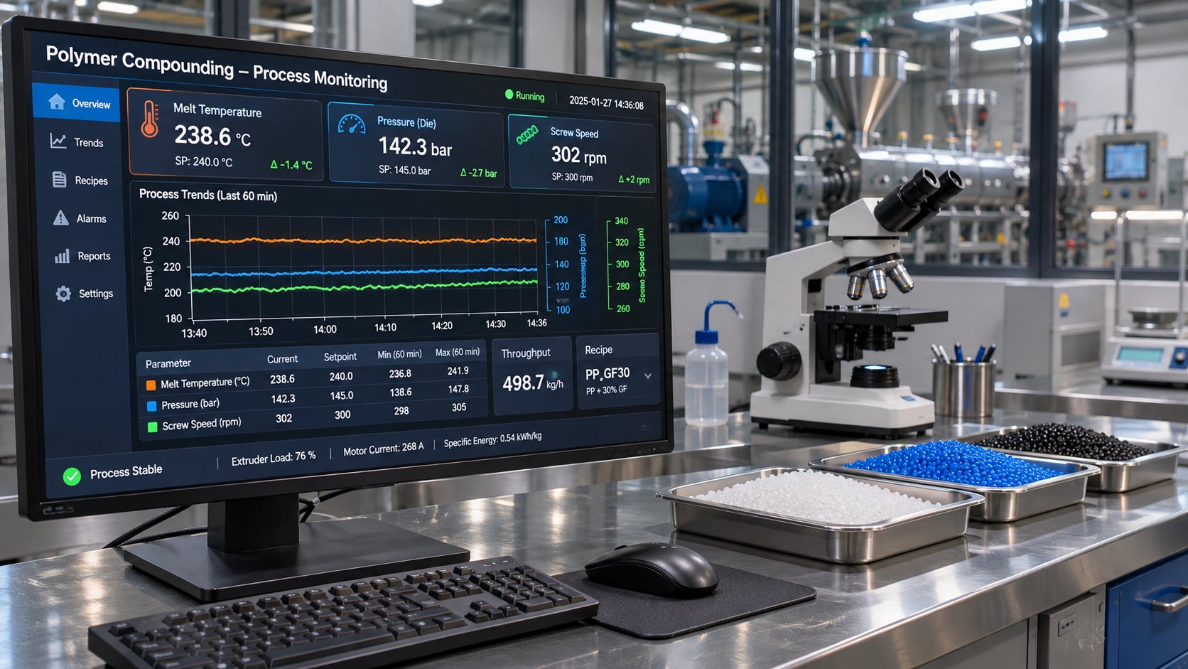
SME is the shaft power delivered to the screw divided by mass throughput, expressed in kWh/kg. If the drive is putting a given number of kilowatts into the screw and the line is producing a given number of kilograms per hour, the ratio captures how much mechanical work each kilogram of material absorbs. As Integrated Control Technologies explains, SME is the most informative component of the energy calculation because it reflects what is actually happening inside the barrel — melt viscosity, screw geometry, clearances, and the material's resistance to flow all show up in the torque needed to push a given rate through the die.
Why does this matter for mixing? Because mixing intensity and energy input are directly coupled. The shear and elongational stresses that break agglomerates and reorient flow streams are generated by the mechanical energy the screw transfers to the melt. Higher SME generally means more intense mixing; lower SME means less. By tracking SME continuously during production, you gain a real-time window into whether the process is delivering the mixing work your formulation requires.
The diagnostic power of SME shows up in how it responds to process changes:
- Rising SME on a stable recipe — Could indicate increased melt viscosity from a lower-MFR resin lot, higher moisture content raising resistance, or a screen pack loading up and increasing head pressure. The material is harder to push, so the screw works harder per kilogram.
- Falling SME on a stable recipe — Often signals screw element wear. As flight clearances widen, more melt leaks back over the flights instead of moving forward. The screw delivers less effective shear per revolution, and specific output (kg/h per rpm) gradually declines. This is one of the clearest wear indicators available without pulling the screw — and it directly correlates with reduced mixing effectiveness.
- Step change in SME at a lot boundary — Points to material variation, not equipment. A higher-MFR lot will drop SME; a lower-MFR lot will raise it. Knowing this prevents unnecessary screw pulls or process adjustments that chase a "problem" that is actually just a new lot of resin.
- Gradual drift over weeks or months — The hallmark of mechanical wear. A slow, steady climb in screw speed needed to maintain throughput — or a declining SME at constant speed — tells you element replacement should be scheduled before product quality deteriorates visibly.
Getting reliable SME data requires two clean inputs. The numerator — drive power — comes from the motor drive, ideally read digitally over an industrial network rather than inferred from an analog load meter. The denominator — mass throughput — comes from a gravimetric feeder or blender providing a continuous, weight-based rate. Without accurate mass flow, the SME calculation introduces noise that obscures the trends you are trying to detect. ICT recommends sampling both inputs at the same rate, averaging over a one-to-five-minute window, and filtering out non-steady-state intervals like startups, purges, and feeder refills to keep the trend clean.
A practical nuance: SME is not constant across throughput rates. Fixed losses like gearbox friction and drive overhead get spread over more kilograms at higher rates, so the baseline shifts. The best practice is to establish an SME baseline for each recipe at each normal operating rate band, then track deviation from that specific baseline rather than comparing a single absolute number across conditions.
Using Process Data to Drive Continuous Improvement
SME becomes truly powerful when you stop treating it as a standalone number and start correlating it with product quality data. That correlation creates a feedback loop — and the feedback loop is what transforms a static process into one that continuously improves.
Here is how that loop works in practice. You establish an SME baseline during a validated production run where product quality meets all specifications — dispersion rating, color uniformity, mechanical properties, MFR. That baseline becomes the reference. Every subsequent production run generates SME data that you compare against the reference for the same recipe and rate band. When SME deviates beyond a defined threshold — say, a sustained shift of more than 5-10% — you investigate before quality slips, not after.
The investigation follows a simple decision tree:
- Step change at a material lot boundary? — Check incoming material properties (MFR, moisture, filler lot). Adjust process parameters if needed, and update the baseline if the new lot represents a permanent formulation shift.
- Gradual drift with no material change? — Schedule a screw and barrel measurement during the next planned downtime. Compare flight depths and element clearances against the original specifications. Replace worn elements and re-establish the baseline.
- Shift-to-shift variation on the same lot? — Investigate operator practice differences. As process data experts note, shift reports can reveal that one crew runs hotter profiles or higher screw speeds than another for the same product — differences that show up clearly in SME trends but might otherwise go unnoticed.
This data-driven approach also informs element replacement schedules. Rather than replacing kneading blocks on a fixed calendar — which either wastes good elements or lets worn ones run too long — you replace based on measured performance decline. When SME for a given recipe drifts below the threshold that correlates with acceptable dispersion ratings, the elements have told you they need attention. That is predictive maintenance grounded in process physics, not guesswork.
The same framework scales to polymer mixing process optimization over time. Every screw configuration change, every new formulation trial, and every scale-up generates an SME data point paired with quality results. Over months and years, that dataset reveals which configurations deliver the best quality at the lowest energy cost, which materials are most sensitive to SME variation, and where the process window is tightest. It turns tribal knowledge into institutional data.
Specific mechanical energy is the single most informative metric for correlating mixing process input with product quality output — track it per recipe, per rate, and per shift, and your process will tell you what it needs before your customers tell you what it failed to deliver.
The extrusions definition of success is not a perfect screw design frozen in time. It is a process that measures itself, corrects itself, and improves itself — continuously. SME gives you the vocabulary for that conversation between machine and engineer. Combine it with structured quality evaluation, disciplined baseline management, and the material-first thinking covered throughout this article, and the gap between your screw configuration and the mix quality your product demands starts to close. Not once, but every shift, every lot, every production run.
Frequently Asked Questions About Extrusion Mixing
1. What is the difference between distributive and dispersive mixing in extrusion?
Distributive mixing rearranges minor-phase components — pigments, additives, filler particles — throughout the polymer melt by repeatedly splitting, folding, and recombining the flow stream. It improves spatial uniformity without reducing particle size. Dispersive mixing, on the other hand, applies high shear or elongational stress to physically break apart agglomerates and reduce droplet size. Most compounding operations need both modes in sequence: dispersive action first shatters agglomerates, then distributive action spreads the resulting fragments evenly. Screw elements like 90-degree neutral kneading blocks primarily deliver dispersive stress, while toothed mixing elements and gear mixers excel at distribution.
2. How does kneading block stagger angle affect mixing performance?
Stagger angle is the angular offset between consecutive discs in a kneading block, and it directly controls the balance between forward conveying and mixing intensity. A 30-degree forward stagger emphasizes gentle conveying with moderate distributive blending. A 45-degree angle offers the best general-purpose balance of mixing and throughput. At 60 degrees, shear intensity increases significantly for stronger dispersive action but melt temperature rises. A 90-degree neutral stagger eliminates all forward conveying, maximizing dispersive energy input — ideal for breaking stubborn filler agglomerates. Reverse stagger angles create back-conveying action used as melt seals ahead of venting zones. Selecting the right angle depends on whether your application needs gentle blending or aggressive particle breakup.
3. What is specific mechanical energy (SME) and why does it matter for extrusion mixing?
SME measures the shaft power delivered to the screw divided by mass throughput, expressed in kWh/kg. It captures how much mechanical work each kilogram of material absorbs during processing, making it the most informative real-time indicator of mixing intensity. Rising SME on a stable recipe may signal increased melt viscosity from moisture or a new resin lot. Falling SME often indicates screw element wear, which widens clearances and reduces effective shear. By tracking SME per recipe and per rate band, engineers can detect process drift before it causes visible quality problems, schedule element replacements based on measured performance decline, and maintain consistent mixing outcomes across production campaigns.
4. Why does extrusion mixing fail during scale-up from lab to production?
When extruder diameter increases, internal volume scales with the cube of diameter while barrel surface area scales with the square. This mismatch reduces the area-to-volume ratio, limiting heat removal and changing shear rate distribution and residence time. A screw configuration optimized on a small laboratory extruder may deliver drastically different energy input at production scale. Documented case studies show SME dropping by as much as 69% during direct scale-up, causing phase separation and unusable product. Successful scale-up typically requires matching SME across scales, adjusting screw design and temperature profiles, and using pilot-scale trials to validate process windows before committing to full production runs.
5. How do material properties influence extrusion mixing screw design?
Material characteristics dictate the type and intensity of mixing your screw must deliver. Melt viscosity determines how much shear stress the screw can generate — higher-viscosity polymers produce greater stress at the same screw speed. The viscosity ratio between blend components governs droplet breakup efficiency, with ratios near unity being optimal for dispersive mixing. Filler properties like particle size, aspect ratio, and surface treatment change the dispersive energy required: untreated nanofillers demand far more shear than pre-coated micron-scale minerals. Abrasive fillers accelerate element wear, gradually reducing mixing effectiveness over time. Engineers should always define mixing targets based on these material science factors first, then select screw geometry and process parameters to match.
Written by
Nanhaiya Technical Team
Zhoushan Nanhaiya Plastic Machinery Co., Ltd.
The Nanhaiya technical team supports screw and barrel manufacturing projects through application review, technical communication, custom manufacturing coordination, and production and quality control.
Discuss Your Application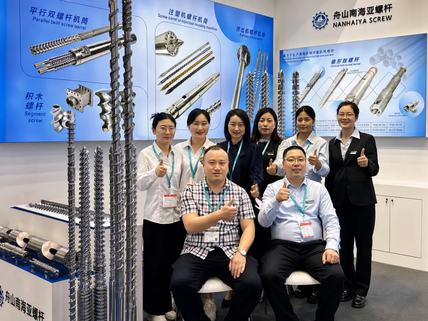
Related Articles
More insights on screw barrel technology and plastics processing.

Carbon Black Dispersion Fundamentals Every Formulator Gets Wrong
Nov 10, 2026
Learn why carbon black dispersion fails and how to fix it. Grade selection, dispersant chemistry, equipment, QC testing, and stability — all in one guide.
Read Article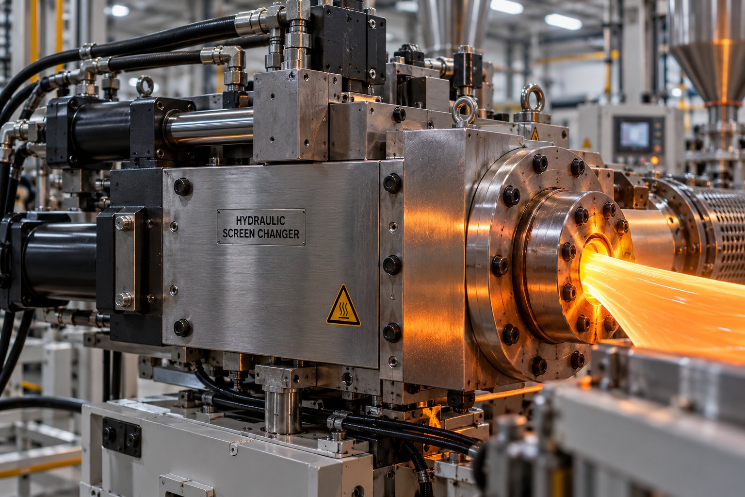
Extruder Screen Changer Decoded: Types, Mesh Sizing, and True Cost
Nov 9, 2026
Learn how to choose the right extruder screen changer by type, mesh size, and total cost of ownership. Covers recycling, maintenance, and ROI analysis.
Read Article
Talc Filled Polypropylene: 10% To 40% Loading Data Compared
Nov 6, 2026
Talc filled polypropylene compared at 10% to 40% loading. Property trends, processing tips, defect fixes, and a material selection guide for engineers.
Read ArticleLooking for something else?
Search by material, symptom or product and jump straight to the relevant page.
These are navigation suggestions based on keyword matching — not a quotation, not a delivery commitment, and not a substitute for engineering review. Final specification is confirmed by our engineers against your drawings and processed material.
Need help with screw barrel selection?
Share your machine model, processed material and application. Our team can help with pricing and technical support.