

What a Check Ring Does and Why Every Molder Should Understand It
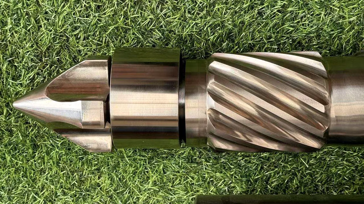
A check ring — also called a non-return valve or sliding ring valve — is a mechanical component mounted at the front of the injection screw that acts as a one-way valve for molten plastic. During screw recovery, it slides open to let melted resin flow forward and accumulate into the shot. During injection, it seats closed to block backflow, ensuring full injection pressure reaches the mold cavity. In short, every consistent part you mold depends on this single assembly doing its job cycle after cycle.
Defining the Check Ring in the Injection Molding Process
Imagine pressing a syringe with a leaky plunger. No matter how precisely you push, the volume delivered changes unpredictably. That is exactly what happens inside an injection barrel when the check ring fails to seal reliably. The component sits between the screw tip and the rear seat, and its sole purpose is to guarantee that melt travels in one direction — forward into the mold. As Plastics Technology puts it, "How well the check ring functions to prevent backflow determines the consistency of shot size and cushion." Two seals must form simultaneously: one between the ring and its seat, and another between the ring's outer diameter and the barrel wall. Wear on either surface compromises the entire system.
Why Check Ring Performance Is a Hidden Driver of Part Quality
Here is the problem most plants face: when short shots appear, cushion positions drift, or part dimensions fall out of spec, the troubleshooting reflex is to adjust temperatures, pressures, or hold times. These process tweaks can temporarily mask the real culprit — a worn or inconsistent check ring assembly. As Turner Group highlights, check ring deterioration happens gradually and is easily mistaken for material variation, machine control issues, or changing mold conditions. A classic injection molding check ring test — running short shots with pack pressure disabled and measuring cushion scatter — can reveal the truth in minutes. Yet many shops never perform one until defects are already out of control.
All check rings leak. Every single one. The goal is not zero leakage — it is consistent, repeatable leakage from shot to shot. A ring that leaks the same small amount every cycle can still produce excellent parts. A ring that leaks unpredictably destroys quality, even if average leakage looks acceptable.
This article is built for process technicians, maintenance teams, and plant engineers who want the complete picture — from internal anatomy and mechanical cycle, through material selection and diagnostic testing, to the rebuild-versus-replace decision. Understanding the check ring for injection molding at this depth turns a reactive troubleshooting headache into a proactive quality advantage. And the place to start is inside the assembly itself, where every wear surface tells a story about what is happening to your process.
Inside the Check Ring Assembly and Its Individual Components
Every check ring injection molding machine relies on a compact assembly of just three or four parts working in concert. Yet most technicians treat it as a single "black box" component — something that either works or does not. That mindset misses the reality that each individual piece has its own geometry, its own wear profile, and its own failure mode. Understanding what is inside the assembly is the first step toward diagnosing why your process drifts.
Core Components of the Non-Return Valve Assembly
A standard sliding check ring assembly consists of three primary components, though many modern designs use a four-piece configuration for improved durability. The screw tip (sometimes called the torpedo, retainer, or cone) threads onto the front of the screw and forms the leading edge of the assembly. Its tapered or streamlined shape guides molten resin through the flow channels during recovery and provides the front seat surface that the ring contacts as it slides forward. In a four-piece design, the front seat is a separate hardened insert rather than an integral part of the retainer — a distinction that significantly extends service life in abrasive applications.
The check ring itself — the sliding ring — is a free-floating cylindrical band that rides between the screw tip and the rear seat. It does not rotate with the screw during plasticating. Instead, it slides axially: forward against the screw tip during recovery to open flow channels, and rearward against the rear seat during injection to seal them off. Its outer diameter runs in close proximity to the barrel bore, forming one of two critical sealing surfaces.
The rear seat (also called the back-flow stop or seat ring) is a stationary component that threads or locks onto the screw just behind the check ring. When the ring slides rearward during injection, its flat or angled face mates against the rear seat to create an axial seal — the primary barrier preventing backflow over the screw flights.
Here is a breakdown of each component, its alternate names, its role, and where wear concentrates:
| Component Name | Alternate Names | Function | Key Wear Surfaces |
|---|---|---|---|
| Screw Tip | Torpedo, Cone, Retainer | Threads onto screw; guides melt flow through channels; provides front seat contact surface | Front seat face (notching from ring impact), taper surface (erosion from filled resins) |
| Check Ring | Sliding Ring, Non-Return Ring | Slides axially to open flow during recovery and seal flow during injection | Outer diameter (radial wear against barrel ID), rear face (axial sealing surface against rear seat), front face (contact with screw tip seat) |
| Rear Seat | Back-Flow Stop, Seat Ring | Provides the stationary sealing face that the check ring mates against during injection | Forward-facing sealing surface (scoring, galling, erosion from repeated ring contact) |
| Front Seat (4-piece design) | Seat Insert, Hardened Seat | Separate hardened insert on screw tip that absorbs impact of ring during recovery | Contact face (notch wear from check ring impact at high screw speeds) |
How Sealing Surfaces Work Together
Two distinct sealing zones must function simultaneously every time the screw pushes forward. The first is the axial seal — the face-to-face contact between the check ring's rear surface and the rear seat. When injection pressure builds (often reaching 20,000 to 45,000 psi of plastic pressure in thin-wall applications, as noted by injection molding expert John Bozzelli), the ring is driven rearward and pressed firmly into the seat. The quality of this seal depends on how precisely the mating surfaces conform to each other — any scoring, galling, or uneven wear creates micro-channels where melt escapes backward.
The second is the radial seal — the clearance between the check ring's outer diameter and the barrel's inner diameter. This gap must be tight enough to prevent significant melt bypass around the ring, yet loose enough that the ring slides freely without galling against the barrel wall. You will often hear this described in terms of diametral clearance, typically measured in thousandths of an inch. Too tight, and the ring binds or sticks. Too loose, and resin bleeds past the OD during every injection stroke.
The interaction between these two sealing zones shifts with the phase of the molding cycle. Here is how each component behaves during plasticating versus injection:
| Cycle Phase | Screw Tip | Check Ring | Rear Seat | Sealing Status |
|---|---|---|---|---|
| Plasticating / Recovery | Rotates with the screw; taper guides melt forward through flow channels | Pushed forward against the screw tip's front seat by melt pressure; flow channels open | Rotates with the screw; no contact with check ring rear face | Open — melt flows freely past the assembly to accumulate the shot ahead of the screw tip |
| Injection / Hold | Advances forward with the screw; front seat disengages from ring as ring moves rearward | Driven rearward by pressure reversal; seats against rear seat face; OD seals against barrel ID | Advances with the screw; forward face receives and seals against check ring | Closed — axial seal (ring to rear seat) and radial seal (ring OD to barrel ID) both active to block backflow |
Wear Points That Degrade Assembly Performance
Here is the critical insight many maintenance teams overlook: the injection mold check ring assembly is only as strong as its weakest sealing surface. A brand-new check ring installed on a scored rear seat still leaks. A pristine rear seat paired with a ring whose OD is worn undersized still lets melt bypass radially. Each surface degrades at its own rate depending on the resin being processed, injection pressure, screw speed, and material hardness.
- Ring OD wear — Abrasive resins (glass-filled, mineral-filled) gradually reduce the outer diameter, widening the radial gap to the barrel wall. This is the most common form of degradation and often the first to become measurable.
- Rear seat face erosion — Repeated high-pressure contact with the check ring, combined with melt flowing across the sealing face at high velocity, scores and erodes the seat surface over time.
- Front seat notching — During recovery, the ring impacts the screw tip's front seat at the end of its forward travel. Excessive screw RPM accelerates this notching, as Molders Services points out, causing the ring to over-travel and delay its seating during injection.
- Barrel ID wear — While not part of the assembly itself, the barrel bore is a critical partner. If the barrel ID has worn oversize, even a new ring cannot form an adequate radial seal. A check ring stuck in an injection molding machine often signals that the ring has galled against a rough or damaged barrel surface.
Corrosion adds another layer of complexity. Resins that off-gas corrosive byproducts — PVC, certain flame-retardant compounds, acetals — attack sealing surfaces chemically rather than mechanically. The damage may not be visible as traditional wear lines but instead appears as pitting or surface roughening that prevents a clean seal.
Because every component in the assembly shares the sealing responsibility, inspecting just the ring or just the seat in isolation gives an incomplete picture. Effective evaluation means pulling the entire assembly and examining all mating surfaces together — a discipline that pays dividends when it is time to decide whether a quick rebuild can restore performance or a full replacement is the smarter investment.
How the Check Ring Functions Through the Injection Cycle
Knowing what each component looks like on a workbench is one thing. Understanding how those parts behave under thousands of PSI of melt pressure, at hundreds of degrees, in a fraction of a second — that is where real troubleshooting skill begins. The check ring does not simply "open" and "close" like a light switch. It responds to shifting pressure differentials throughout every single shot, and the speed and consistency of that response directly shapes your part quality.
Let's walk through one complete cycle, from the moment the screw begins turning to the instant hold pressure releases.
Melt Flow During Plasticating and Recovery
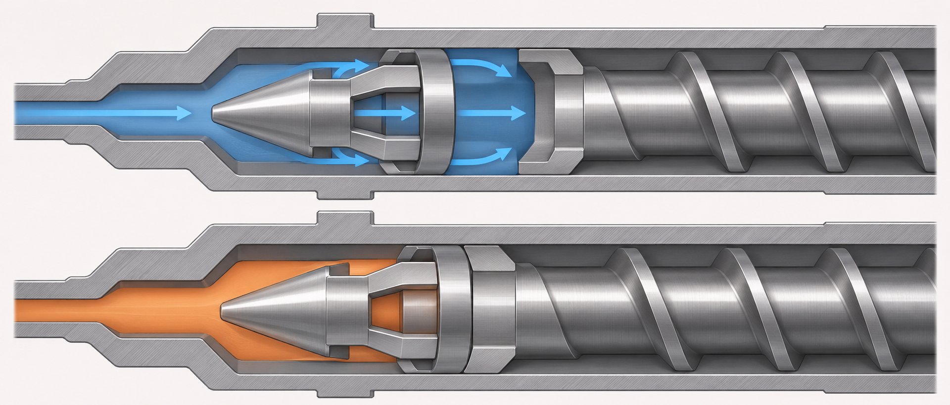
Picture the screw spinning inside the barrel. As it rotates, the flights convey resin pellets forward, shearing and melting them along the way. Molten plastic accumulates ahead of the screw tip, and that growing pool of melt generates pressure in front of the assembly. This forward melt pressure pushes the check ring forward along the screw tip until it contacts the front seat shoulder, effectively pulling the ring away from the rear seat.
With the ring seated forward, an annular flow channel opens between the ring's inner bore and the screw tip's outer surface. Molten resin streams through this gap and collects in the shot-accumulation zone ahead of the tip. The screw simultaneously retracts under the building melt pressure (controlled by back pressure settings on the machine), and this retraction distance determines the shot size.
During this entire recovery phase, the ring floats freely — it does not rotate with the screw. It simply rides forward, held in the open position by the pressure differential across it. The injection molding check ring clearance between the ring's inner diameter and the screw tip governs how much flow restriction exists during recovery. Too tight, and you create excessive pressure drop that slows recovery and generates unwanted shear heat. Too loose, and you reduce the ring's ability to seat cleanly later in the cycle because melt can carry degraded material into the sealing surfaces.
Ring Closure at the Start of Injection
This is where the magic — or the heartbreak — happens. Screw rotation stops. The hydraulic or electric drive behind the screw switches from rotational to linear motion and rams the screw forward. Instantly, the pressure landscape reverses. The melt ahead of the screw tip is now being pushed toward the mold, and the melt behind the ring is being pressurized by the advancing screw flights.
That reversal creates a pressure differential that drives the check ring rearward. It slides off the front seat, travels a few millimeters axially, and seats against the rear seat face. The axial seal forms. Simultaneously, the ring's outer diameter presses against the barrel bore, completing the radial seal. Both seals are now active, and injection pressure — often 15,000 to 30,000 psi or more — transmits cleanly through the melt column ahead of the sealed assembly and into the mold cavity.
Here is the critical detail: closure is not instantaneous. The ring must physically travel from the forward open position to the rearward sealed position, and during that brief transit window, melt can and does leak backward past the assembly. Every shot loses a small amount of material to this backflow. In a healthy assembly, the ring seats in roughly 0.1 to 0.3 seconds and the leakage volume is tiny and — most importantly — consistent from shot to shot.
A worn assembly tells a different story. If the sealing faces are scored, if the ring OD has worn undersized, or if carbon buildup restricts the ring's free movement, closing speed becomes erratic. One shot the ring seats quickly; the next it hesitates. That variability in closure timing means the actual volume of melt delivered to the mold changes unpredictably, even though the machine repeats the exact same screw stroke every cycle. As Turner Group puts it, "The machine may repeat the same screw movement, but the actual volume of material delivered to the mold can change." The result is cushion scatter, weight variation, and dimensional inconsistency — classic injection molding check ring issues that get blamed on everything except the real culprit.
Connection to Decoupled Molding and Process Consistency
Why does ring closure consistency matter so much in a modern molding operation? Because the entire foundation of scientific molding — specifically decoupled injection molding — rests on the assumption that the machine delivers a repeatable volume of melt into the cavity during the fill stage.
In a decoupled process, fill is velocity-controlled to reach 95–99% cavity volume, then the machine switches to pressure control for packing. Fill time consistency is the primary quality indicator during stage one. If your fill time varies more than roughly ±0.05 seconds shot to shot, something is mechanically wrong — and the check ring is the first suspect. A ring that leaks unpredictably during closure steals a different volume of melt each cycle, making true velocity-controlled fill impossible to achieve regardless of how precise your machine's servo drives are.
The impact extends beyond a single machine. One of the greatest advantages of decoupled molding is process transferability — the ability to move a validated process from one press to another, or even from one facility to another, with minimal re-tuning. That transferability depends on physics-based parameters like fill time and pack pressure remaining consistent. If the check ring on the source machine seals differently from the one on the destination machine, fill time shifts, pack behavior changes, and the carefully documented process falls apart on arrival. This is why experienced process engineers insist on verifying check ring performance on both machines before attempting a transfer.
A decoupled molding process is only as repeatable as the non-return valve that controls how much melt actually reaches the cavity each cycle.
Injection molding check ring design plays a direct role here. The geometry of the flow channels, the mass of the ring, the surface finish of the sealing faces — all of these influence how quickly and how consistently the ring transitions from open to closed. A heavier ring with a wider sealing face may seat more firmly but respond more slowly. A lighter ring with a narrow seat may close faster but wear sooner under high-tonnage packing pressures. Choosing the right design for your specific application — and maintaining it within tolerance — is what separates a process that drifts from one that holds steady across millions of shots.
That design choice is far from one-size-fits-all. The two major families of non-return valve designs — sliding ring and locking ring — offer fundamentally different approaches to the closure problem, each with distinct trade-offs in speed, consistency, maintenance, and cost.
Sliding Ring vs Locking Ring Designs Compared
The closing behavior described in the previous section — how fast the ring seats, how consistently it repeats, and how much melt escapes during the transition — varies dramatically depending on the non-return valve design installed on your screw. Two primary design families dominate check ring injection molding applications, and each takes a fundamentally different mechanical approach to solving the same problem: stopping backflow quickly and doing it the same way every single shot.
Choosing between them is not just a purchasing decision. It is a process quality decision that ripples into part weight consistency, color change efficiency, maintenance scheduling, and even barrel wear rates. Let's break down what distinguishes each family and where each one earns its place on the production floor.
Sliding Ring Design and Its Advantages
The sliding ring — also called a free-floating ring — is the most widely used injection molding screw check ring design in the industry. Its popularity comes down to simplicity. The ring sits loosely between the screw tip and the rear seat, sliding axially without any mechanical connection to the screw itself. During recovery, melt pressure pushes it forward to open flow channels. During injection, the pressure reversal drives it rearward against the rear seat to form a seal. No pins, no detents, no springs — just physics.
That simplicity delivers several practical advantages:
- Easy inspection and replacement — Disassembly takes minutes. Unthread the screw tip, slide off the ring, inspect or swap the worn component, and reassemble. No special tools, no complicated re-timing procedures.
- Fast color and material changes — Because the ring floats freely and does not interlock with the screw tip geometry, there are fewer internal crevices where old material can hang up. Purging flushes through the flow channels more efficiently, reducing transition scrap.
- Lower cost — Fewer machined features and looser manufacturing tolerances relative to mechanically-actuated designs keep both the part cost and sourcing lead time down.
- Reduced barrel wear — This is a critical and often underappreciated advantage. Because the ring does not rotate with the screw during plasticating, it imposes far less frictional wear on the barrel bore compared to designs where the ring spins. John Bozzelli of Injection Molding Solutions has pointed out that locking-ring designs can cause significant barrel scoring in as few as 2,000 hours of operation — a failure mode sliding rings are far less likely to produce.
The trade-off? Closure speed and closure consistency. Because the ring relies entirely on the pressure differential to drive it rearward, any variation in melt viscosity, back pressure, or ring-to-tip friction affects how quickly and uniformly it seats from shot to shot. For many general-purpose applications — commodity resins, moderate tolerances, standard wall thicknesses — that variation is small enough to be inconsequential. For ultra-tight-tolerance work, it can matter.
Locking Ring and Mechanically-Actuated Designs
Locking ring check valves — sometimes called castle tips because of the castellated features that key the ring into the screw tip — take a different mechanical approach. Instead of floating freely, the ring interlocks with the retainer so that it rotates with the screw during recovery. When injection begins, the ring shifts axially to seat against the rear seat, just like a sliding ring. The key difference is that the mechanical engagement between the ring and the retainer is designed to provide a faster, more positive seating action.
Beyond locking rings, the broader family of mechanically-actuated non-return valve designs includes ball-check assemblies (where a ball or poppet element plugs a flow orifice) and spring-assisted mechanisms that physically push the sealing element into position rather than relying solely on melt pressure. These designs offer tangible benefits in specific scenarios:
- Faster closure — Mechanical features reduce the ring's travel distance or add spring force that accelerates seating. Less time spent transitioning from open to closed means less melt leaks backward during the critical first moments of injection.
- More repeatable closure — Because the ring's motion is guided or assisted mechanically rather than driven purely by a pressure differential, shot-to-shot closure variation tends to be smaller. This is why these designs are popular in precision medical device molding, optical lens production, and micro-molding where every hundredth of a gram counts.
- Better performance with low-viscosity resins — Thin, runny melts generate less pressure differential to drive a free-floating ring rearward. Mechanically-actuated designs compensate for that weaker driving force, maintaining a reliable seal even when the resin offers little resistance to backflow.
The disadvantages are equally real. Locking rings rotate with the screw, and that rotation drags the ring's outer diameter against the barrel wall every cycle. Over time, this produces circumferential scoring on both the ring and the barrel bore — damage visible as scratches running around the circumference of the ring's OD. Bozzelli's examination of a locking ring after roughly 2,000 hours of service revealed dramatic scoring and carbon buildup, prompting him to openly question the industry's default preference for locking designs. The barrel bore sustains damage too, and unlike a check ring, a barrel is not a quick or inexpensive replacement.
Ball-check and poppet designs carry their own complexity. Internal geometries are more intricate, creating additional surfaces that can accumulate degraded resin or filler material. Color changes take longer because those internal pockets resist purging. Maintenance requires more careful disassembly and inspection since the sealing mechanism involves multiple precisely-fitted internal components.
The following table puts the two primary design families side by side across the criteria that matter most on the production floor:
| Criteria | Sliding Ring (Free-Floating) | Locking Ring / Mechanically-Actuated |
|---|---|---|
| Closure Speed | Moderate — dependent on melt pressure differential | Fast — mechanical features assist or accelerate ring seating |
| Closure Consistency | Good for general-purpose work; slight shot-to-shot variation possible with viscosity changes | Excellent — guided or spring-assisted motion reduces closure variation |
| Ease of Cleaning / Color Changes | Excellent — fewer internal pockets; purging flushes channels effectively | Moderate to Poor — interlocking features and internal cavities trap residual material |
| Cost | Low to Moderate | Moderate to High (depending on complexity of actuation features) |
| Maintenance Complexity | Low — simple disassembly, straightforward inspection | Moderate to High — additional components, tighter tolerances, more wear surfaces |
| Best Suited Resins | Commodity and engineering thermoplastics (PE, PP, ABS, PA, PC); both unfilled and moderately filled grades | Low-viscosity resins, precision-grade materials, LSR, and applications where minimal backflow variation is critical |
| Typical Applications | General-purpose molding, consumer products, automotive components, packaging | Precision medical devices, optical lenses, micro-molding, thin-wall electronics |
| Barrel Wear Impact | Minimal — ring does not rotate against barrel wall | Significant — rotating ring can score barrel bore, especially with abrasive resins |
Matching Design Type to Application Requirements
So which non-return valve design belongs on your machine? The honest answer is that resin type, part tolerance requirements, and production volume all weigh into the decision — and the "best" choice for one application may be the worst for another.
Consider heat-sensitive materials like PVC or POM (acetal). Both degrade rapidly when exposed to extended residence time or stagnant melt zones. These resins benefit from the streamlined, low-dead-spot flow paths that a well-designed sliding ring assembly provides. The fewer internal pockets and mechanical interlocks in the flow channel, the fewer places where resin can hang up, overheat, and decompose into contamination that fouls the sealing surfaces and discolors subsequent shots.
Glass-filled resins flip the priority entirely. Whether you are running 30% glass-filled nylon or 40% glass-filled polypropylene, the exposed glass fiber ends on each pellet act like liquid sandpaper against every surface they contact. The ring's sealing faces, the seat surfaces, and the barrel bore all take a beating. In these applications, the material of the check ring matters more than the mechanical design. A sliding ring made from CPM 10V powder metallurgy steel or a carbide-tipped assembly will outlast a locking ring made from standard H-13 tool steel — regardless of how cleverly the locking mechanism works. Abrasion resistance trumps closure speed when the filler content is high enough to wear through hardened steel in weeks.
For thin-wall packaging and high-speed applications, closure speed becomes the dominant factor. The injection phase happens so quickly — sometimes in under half a second — that even a small delay in ring seating means a proportionally larger percentage of the shot leaks backward. Mechanically-actuated designs or poppet-style quick shut-off valves earn their premium in these environments because every millisecond of closure delay translates directly into fill inconsistency.
Some machine OEMs recognize that no single design serves all applications and offer proprietary non-return valve configurations optimized for their specific barrel and screw geometries. These OEM-specific designs may incorporate features like stepped-angle seats or radiused sealing faces that improve seal quality regardless of whether the ring is sliding or locking. One study referenced by Bozzelli showed an 85% improvement in sealing performance for radiused seats compared to standard near-mating-angle designs — a striking figure that suggests seat geometry may matter as much as the overall valve type.
The best non-return valve design is the one matched to your specific resin, tolerance requirements, and production reality — not the one that dominates the market by default.
Design selection sets the stage, but even the ideal check ring types for an injection molding machine will fail prematurely if the metallurgy cannot withstand the resin being processed. The material the ring is made from — and how that material interacts with your specific polymer chemistry — is the next critical variable that separates short-lived assemblies from ones that deliver millions of consistent shots.
Check Ring Materials and Resin Compatibility
The previous section ended with an important truth: even a perfectly chosen valve design fails prematurely when the metallurgy cannot survive the resin flowing through it. Check ring material selection in injection molding is one of the most consequential — and most frequently overlooked — decisions a maintenance team makes. Choose correctly, and a single assembly delivers millions of consistent shots. Choose poorly, and you could be pulling a destroyed ring out of the barrel in a matter of weeks, wondering what went wrong.
Three properties govern whether a material survives in service: wear resistance (the ability to withstand abrasive filler particles grinding against sealing surfaces), chemical resistance (the ability to tolerate corrosive off-gassing and acidic melt byproducts), and dimensional stability (the ability to hold tight tolerances under sustained high temperatures and pressures without softening or distorting). No single material excels at all three, which is why matching the ring material to your specific resin chemistry matters so much.
Tool Steel Options for Standard Applications
For the majority of commodity and unfilled engineering resins — think polyethylene, polypropylene, ABS, or unfilled nylon — standard tool steels remain the most cost-effective and widely available option. Two grades dominate this category:
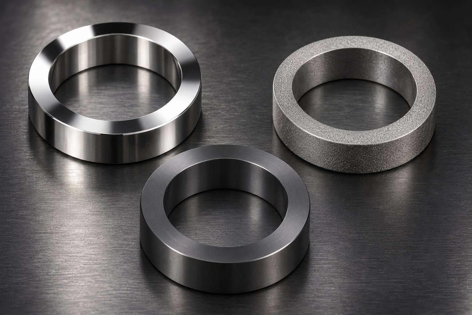
- H-13 tool steel — A hot-work tool steel with good toughness, moderate hardness (typically 42-52 HRC after heat treatment), and solid resistance to thermal fatigue. H-13 handles the cyclic heating and cooling of the injection process well and is the default material on most OEM-supplied check ring assemblies. Its limitation is abrasion resistance — glass fibers and mineral fillers will wear through H-13 surfaces relatively quickly.
- D-2 tool steel — A high-carbon, high-chromium cold-work steel that achieves higher hardness than H-13 (typically 58-62 HRC) and offers improved wear resistance thanks to its chromium carbide content. D-2 is a step up when running moderately filled resins — say, 10-15% glass content — or when processing runs are long enough that H-13's wear rate becomes a maintenance burden. Its trade-off is reduced toughness; it is more brittle than H-13 and can chip under high-impact conditions.
If your plant runs unfilled commodity polymers on moderate cycles, standard tool steel check rings deliver solid value. The parts cost less, they are readily available from virtually every screw and barrel supplier, and replacement lead times are short. The mistake many shops make is sticking with these same materials when they switch to more aggressive resins — a decision that burns through assemblies and creates quality problems seemingly out of nowhere.
CPM Steels, Carbide, and Coatings for Demanding Resins
When fillers, reinforcements, or corrosive chemistries enter the picture, standard tool steels cannot keep up. This is where premium check ring wear resistant materials earn their investment back many times over.
CPM (Crucible Particle Metallurgy) steels represent the workhorse upgrade for abrasive resin applications. Unlike conventionally cast steels, CPM grades are produced through a powder metallurgy process that distributes extremely hard vanadium carbides uniformly throughout the steel matrix. The result is dramatically superior abrasion resistance while maintaining reasonable toughness.
- CPM 9V — With approximately 9% vanadium content and achievable hardness of 53-55 HRC, CPM 9V is widely used for check ring assemblies processing glass-filled nylons, glass-filled polycarbonates, and mineral-filled polyesters. It offers roughly 4-6 times the abrasion resistance of H-13, depending on filler type and loading percentage.
- CPM 10V — Pushing vanadium content to nearly 10% and achievable hardness to 60-62 HRC, CPM 10V is the premier choice for heavily loaded glass-filled resins (30%+ glass content) and long-fiber reinforced materials. A CPM steel check ring for glass filled resin applications in this range can last 8-10 times longer than a standard H-13 assembly under identical processing conditions.
When even CPM steels wear too fast — think ceramic-filled engineering polymers, or extremely high-volume production with aggressive filler loads — carbide enters the conversation. Carbide-tipped check ring components feature tungsten carbide inserts brazed onto the critical sealing surfaces, while full-carbide assemblies machine the entire ring and seat from solid tungsten carbide stock. A carbide check ring on an injection molding machine running 40%+ glass-filled resins at high injection speeds can outlast tool steel by 15-20 times. The cost is significantly higher, but in applications where downtime for ring changes disrupts production schedules, the math often favors carbide.
Specialty coatings and surface treatments offer an alternative path to extended life, sometimes at lower cost than a full material upgrade:
- Stellite (cobalt-chromium alloy) — Applied as a hard-facing overlay on sealing surfaces, Stellite provides excellent resistance to both abrasion and corrosion. It is particularly effective on rear seat faces that see repeated high-pressure metal-to-metal contact with the check ring.
- Chrome plating (hard chrome) — Adds a thin, extremely hard surface layer (65-72 HRC effective hardness) that resists wear and corrosion. Chrome plating works well on ring ODs to extend barrel-to-ring radial seal life. However, the layer is thin and will eventually wear through, requiring re-plating.
- Nitriding — A heat-treatment process that diffuses nitrogen into the steel surface, creating a hardened case without adding material thickness. Nitrided surfaces resist adhesive wear and mild abrasion, and they also improve corrosion resistance modestly. Nitriding is a cost-effective treatment for H-13 components running semi-abrasive compounds.
Here is how the primary material options compare side by side:
| Material / Treatment | Hardness Range | Best For (Resin Types) | Relative Cost | Expected Wear Life Multiplier vs. Standard Tool Steel |
|---|---|---|---|---|
| H-13 Tool Steel | 42-52 HRC | Unfilled commodity resins (PE, PP, ABS), unfilled engineering resins (PA, PC, PBT) | Low (baseline) | 1x (baseline) |
| D-2 Tool Steel | 58-62 HRC | Lightly filled resins (10-15% glass), moderate-wear applications | Low to Moderate | 2-3x |
| CPM 9V (Powder Metallurgy) | 53-55 HRC | Glass-filled and mineral-filled engineering resins (15-30% filler content) | Moderate to High | 4-6x |
| CPM 10V (Powder Metallurgy) | 60-62 HRC | Heavily glass-filled resins (30%+), long-fiber reinforced compounds, ceramic-filled grades | High | 8-10x |
| Tungsten Carbide (tipped or solid) | 75-80+ HRA | Extreme-wear applications: 40%+ glass fill, ceramic-filled, high-volume / high-speed cycles | Very High | 15-20x |
| Stellite Hard-Facing | 38-55 HRC (overlay) | Abrasive and corrosive resins; excellent for rear seat face protection | Moderate to High | 3-5x (on treated surfaces) |
| Hard Chrome Plating | 65-72 HRC (surface) | Moderate-wear and mild corrosion environments; ring OD protection | Low to Moderate | 2-4x (until plating wears through) |
| Nitriding (surface treatment) | 60-70 HRC (case) | Semi-abrasive compounds; corrosion-prone resins on budget-conscious schedules | Low | 1.5-3x |
How Resin Chemistry Drives Material Decisions
The table above provides the numbers, but the real decision-making logic starts with one question: what resin are you running?
Abrasive resins — glass-filled nylons, mineral-filled polyesters, glass-filled polypropylenes, and long-fiber-reinforced compounds — demand hardness above all else. The glass fiber ends and mineral particles act as cutting tools against every surface they contact. Upgrading from H-13 to a CPM steel check ring or a carbide assembly is not a luxury in these applications; it is a basic survival strategy. Plants that resist the upfront cost often spend far more on repeated replacements, unplanned downtime, and scrap from degraded sealing performance.
Corrosive resins introduce a different failure mechanism. PVC off-gases hydrochloric acid during processing. Acetals (POM) can release formaldehyde. Flame-retardant compounds — particularly those containing brominated or halogenated additives — produce acidic byproducts that attack steel surfaces chemically. The damage appears as surface pitting and roughening rather than smooth dimensional wear, and it destroys the mirror-finish sealing faces that a check ring depends on. For these resins, corrosion-resistant alloys (Stellite, nickel-based alloys) or protective coatings (chrome plating, nitriding) are essential regardless of filler content. A ring might show almost no dimensional wear and still leak badly because chemical attack has roughened its sealing face beyond functional tolerance.
High-temperature resins such as PEEK, PEI (Ultem), PPS, and liquid crystal polymers (LCP) add thermal stress to the equation. Barrel temperatures in these applications can exceed 700 degrees F, and prolonged exposure at those levels can soften lower-grade tool steels or cause surface oxidation that accelerates wear. CPM steels and carbides maintain their hardness and dimensional stability at elevated temperatures better than standard H-13, making them the natural choice for high-performance polymer processing.
Injection pressure and speed matter here too. High-speed thin-wall molding generates intense pressure spikes during the injection phase — sometimes exceeding 30,000 psi of plastic pressure at the screw tip. That extreme mechanical loading accelerates wear on sealing faces and amplifies the consequences of any softening due to heat. The combination of high temperature and high pressure in engineering resin applications creates a compounding wear environment that can shorten the life of underpowered materials exponentially rather than linearly.
Think of it this way: selecting a check ring material is an engineering decision, not a purchasing decision. The cheapest ring per unit is rarely the cheapest ring per million shots. Documenting your resin type, filler content, barrel temperature range, injection speed, and expected production volume gives you — or your supplier — the data needed to specify the right metallurgy from the start, instead of learning the hard way through premature failures.
Material selection defines how long the assembly survives. But even the best metallurgy cannot compensate for a ring that is the wrong size for the barrel or mismatched to the process demands of the application. Getting the dimensional relationships right — clearances, flow-channel sizing, and sealing-face geometry — is the next piece of the puzzle.
Sizing and Selection Criteria for Your Machine and Process
A check ring built from the finest CPM 10V steel and designed with a perfectly radiused sealing face will still underperform if it is the wrong size for your barrel or mismatched to your process demands. Check ring sizing on an injection molding machine is not a matter of grabbing whatever fits the screw thread and calling it good. The assembly must be dimensionally matched to the barrel bore, the screw tip geometry, the shot size requirements, and the injection speed demands of the specific application. Get any of these relationships wrong, and you introduce the very leakage inconsistency and pressure-drop problems that the previous sections warned about — regardless of how premium the metallurgy is.
Critical Dimensional Relationships
Three dimensional relationships govern how well a check ring assembly performs. Each one balances competing demands, and understanding the trade-offs is what separates a properly specified ring from one that creates more problems than it solves.
Ring OD to barrel ID clearance. This is the radial seal — the gap between the outer diameter of the sliding ring and the inner bore of the barrel. Check ring clearance tolerance in injection molding applications is deliberately kept tight, typically in the range of 0.002 to 0.005 inches on the diameter depending on barrel size and resin type. Too tight, and the ring binds against the barrel wall, causing galling, sticking, and erratic closure. Too loose, and molten resin bleeds past the ring's OD during every injection stroke, creating a leakage path that no amount of axial sealing can compensate for. Abrasive resins widen this clearance progressively over time, which is why monitoring ring OD wear — and barrel bore enlargement — is essential to maintaining seal integrity.
Ring ID to screw tip OD flow-channel area. When the ring slides forward during recovery, the annular gap between the ring's inner bore and the screw tip's outer surface becomes the primary flow channel for molten resin traveling into the shot-accumulation zone. The cross-sectional area of this channel directly determines the pressure drop the melt experiences during plasticating. A channel that is too restrictive raises melt temperature from excess shear, slows recovery time, and can cause degradation in heat-sensitive resins. A channel that is excessively large reduces the pressure differential that drives the ring rearward during injection, potentially slowing closure and increasing backflow. The ideal sizing delivers low restriction during recovery while maintaining enough flow velocity to keep the ring responsive during the transition to injection.
Axial sealing-face width. The contact band where the check ring's rear face meets the rear seat determines how sealing force is distributed across the joint. A wider sealing face spreads the load over a larger area, reducing unit contact pressure and slowing the rate of surface wear — but it also increases the ring's mass and the axial travel distance required to seat fully, which can slow closure. A narrower face concentrates sealing force for a tighter initial seal but wears faster under high pack pressures. For most general-purpose applications, sealing-face widths between 0.060 and 0.125 inches provide a workable balance between seal quality and service life.
Process Parameters That Influence Ring Selection
Dimensions alone do not tell the full story. The process running on the machine shapes how aggressively the assembly is loaded and how much performance margin you need.
Shot size relative to barrel capacity is one of the most underappreciated factors. As injection molding expert John Bozzelli recommends, the working range for a barrel is between 25% and 65% of its total capacity, with an additional 10% safety factor added for check-valve leakage and melt uniformity. Processes running near the upper end of that range place greater mechanical stress on the non-return valve because the screw stroke is longer, the volume of melt being sealed is larger, and any leakage during ring closure represents a proportionally bigger percentage of the total shot. If your shot weight consistently pushes past 65% of barrel capacity, the check ring is fighting an uphill battle every cycle — and cushion consistency will suffer no matter how new the assembly is.
Injection speed drives flow-channel sizing requirements. High-speed thin-wall applications — where fill times can drop below half a second — need generously sized flow channels to minimize pressure loss during recovery and maximize the pressure differential available to drive the ring closed quickly at the start of injection. If the flow area is too restrictive, the machine struggles to build injection velocity, fill times lengthen, and the ring may not seat fast enough to prevent significant backflow before the cavity is filled. Low-speed structural parts with thick walls and long fill times are far less sensitive to flow-channel restrictions; the ring has more time to seat, and the melt pressure differentials are less extreme.
Resin viscosity and filler content round out the selection picture. Low-viscosity resins generate weaker pressure differentials across the ring, meaning the ring must be light enough and well-fitted enough to seat reliably under less driving force. Heavily filled resins demand not only the right metallurgy (covered in the previous chapter) but also slightly more generous clearances to prevent filler-induced binding — while still maintaining a functional radial seal. It is a balancing act that requires knowing your specific material and process, not just your machine specifications.
Information to Gather Before Sourcing a Replacement
When replacement check ring dimensions need to match a specific machine and process, guesswork leads to wrong parts, wasted money, and extended downtime. Before contacting any supplier, your maintenance team should document the following details:
- Screw diameter — The nominal screw size determines the baseline for all assembly dimensions and thread specifications.
- Barrel bore measurement — Do not assume the bore matches OEM spec. Measure the actual current barrel ID at the check ring operating zone, since barrel wear directly affects radial seal performance with any replacement ring.
- Current ring dimensions — Measure the worn ring's OD, ID, axial length, and sealing-face width. These provide the starting point for determining how far the assembly has deviated from its original geometry.
- Resin type and filler content — This drives material selection. Specifying "nylon" is not enough; "PA66 with 33% glass fiber" tells the supplier exactly what wear and chemical environment the ring must survive.
- Typical injection speed and pressure — These parameters influence flow-channel sizing and sealing-face design requirements.
- Shot weight and barrel capacity percentage — Helps the supplier assess whether the existing ring design is adequate or whether an upgraded flow-path geometry is warranted.
- Machine make, model, and screw tip style — Ensures thread compatibility and correct assembly fitment.
- Worn samples, photos, and engineering drawings — Visual evidence of the wear pattern helps a knowledgeable supplier identify the root failure mechanism and recommend the right material and design adjustments.
Thorough documentation transforms the sourcing process from a catalog guessing game into an engineering conversation. Suppliers who take this process seriously — reviewing machine details, drawings, worn samples, photos, and precise dimensions before committing to a quote — are the ones most likely to deliver a correctly specified replacement on the first try. NANHAIYA, for instance, follows exactly this approach for their injection molding spare parts catalog, which includes check rings, screw tips, and non-return valves. Their team assesses part compatibility and manufacturing feasibility against the submitted documentation before quoting, reducing the risk of dimensional mismatches that plague blind catalog orders.
Getting the sizing and material right upfront eliminates one major source of process inconsistency. But even a perfectly specified, freshly installed assembly degrades over time — and the only way to catch that degradation before it damages part quality is through systematic diagnostic testing. The next section lays out exactly how to test your check ring's performance with step-by-step procedures and clear pass/fail criteria.
Step-by-Step Diagnostic Tests for Check Ring Performance
A perfectly sized, correctly specified check ring assembly still wears — and it wears gradually enough that operators rarely notice until defects are already costing money. The only way to catch degradation before it reaches that point is to test proactively. Yet many molding operations never run a formal check ring leakage test procedure until scrap rates spike or a customer complaint forces the issue. By then, the ring may have been leaking inconsistently for weeks or months, with process technicians chasing phantom problems across temperatures, pressures, and hold times instead of looking at the mechanical root cause.
Three diagnostic tests — each targeting a different aspect of non-return valve performance — give you a clear, repeatable picture of how your assembly is behaving. None of them require special equipment beyond what a standard injection molding machine already provides. What they do require is discipline: running them on a scheduled basis, recording results, and tracking trends over time.
Remember the principle from earlier in this article: all check rings leak. These tests do not look for zero leakage. They look for consistent leakage — and they flag the moment consistency breaks down.
Cushion Consistency Test Procedure
This is the most accessible and widely applicable test for evaluating check ring injection molding performance. It requires nothing more than your machine's standard position monitoring and a notepad (or data logging system). The logic is straightforward: if the check ring seals the same way every shot, the cushion position at transfer and at the end of hold should repeat tightly from cycle to cycle. If it does not, something is allowing melt to leak backward inconsistently.
- Establish a stable process. Run the machine at normal production settings until the process has reached thermal equilibrium — typically at least 15 to 20 cycles after startup, or more for large barrel sizes. You want to eliminate any variation caused by temperature stabilization so the test isolates the check ring's behavior.
- Record the cushion position at the velocity-to-pressure (V/P) transfer point for a minimum of 20 consecutive shots. Many modern controllers display this automatically; on older machines, you may need to watch the screw position readout at the exact moment transfer occurs.
- Record the cushion position at the end of hold time for the same 20 shots. This value shows how much the screw advanced during the hold phase — the period when backflow past the check ring has the most direct impact on packing consistency.
- Calculate the range (highest minus lowest) and standard deviation for both data sets. These two numbers quantify how much variation the check ring is introducing into your process.
- Compare results against general benchmarks. For most applications, cushion variation at transfer should fall within ±0.5 mm (approximately ±0.020 inches) of the mean. Variation tighter than ±0.25 mm indicates excellent ring performance. Variation exceeding ±1.0 mm — or a range that spans more than 2-3% of total shot size — signals significant leakage inconsistency and warrants physical inspection of the assembly.
What does this test reveal? It exposes shot-to-shot closure inconsistency. A ring that seats quickly one cycle but hesitates the next produces a wandering cushion because different volumes of melt escape rearward during the critical first moments of injection. As Turner Group emphasizes, monitoring cushion consistency and shot-to-shot part weight provides valuable clues about whether the assembly is closing and sealing consistently — well before defects become visible on the molded part.
One important caution: cushion can appear stable while the check ring leaks inconsistently if the leakage happens to average out over consecutive shots, masking real variation in packing and part weight. This is why the cushion test alone is not sufficient — it should always be paired with at least one of the following two methods for a complete picture.
Pressure Decay and Decompression Testing
This test isolates the check ring's sealing ability from all other variables by pressurizing the melt column and watching how quickly that pressure bleeds away. Think of it as a leak-down test for your injection unit — the same concept an engine mechanic uses to evaluate piston ring condition. A rapid pressure drop means melt is escaping backward past the assembly under static conditions, which tells you the ring cannot hold a seal even without the dynamic forces of an active injection stroke.
- Close the flow path to the mold. Either press the nozzle firmly against the sprue bushing with no mold open signal, or — ideally — use a shut-off nozzle in the closed position. The goal is to trap the melt column between the sealed nozzle and the check ring so that any pressure loss must be attributed to backflow past the valve.
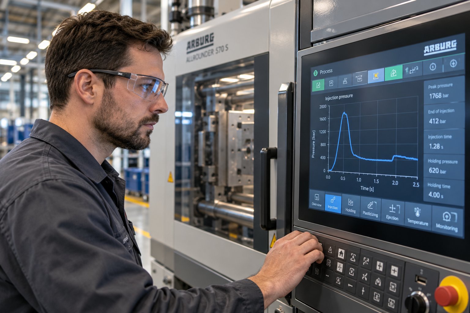
- Build injection pressure. Command the screw forward at normal injection speed and pressure until it reaches a predetermined hold pressure — typically the same hold pressure used in production. Hold that pressure for 5 to 10 seconds, then note the peak hydraulic or specific injection pressure on the machine display.
- Release hold pressure and immediately observe the pressure decay. Switch the injection unit to zero pressure command (or simply end the injection cycle) and watch the residual pressure reading. On machines with real-time pressure graphing, record the pressure trace over a 10- to 30-second window after the hold command is released.
- Measure the rate of decay. Note the pressure value at fixed time intervals — for example, at 5 seconds, 10 seconds, and 30 seconds after the hold command ends. A well-sealing assembly will show a slow, gradual decline as the melt compresses and minor leakage occurs. A worn assembly will show a steep, rapid decline as melt streams backward past the ring and seat.
- Repeat the test three to five times to check for consistency. A ring that produces dramatically different decay curves from one repetition to the next is exhibiting the exact type of intermittent sealing failure that kills process repeatability.
How should you interpret the results? There is no single universal pass/fail pressure value because decay rate depends on melt viscosity, temperature, barrel diameter, and the compressibility of the specific resin. The key metric is relative consistency and rate of decline. A healthy ring produces a slow, repeatable decay curve — the same shape and slope every repetition. A failing ring produces fast, erratic curves. If you are conducting this injection molding check ring pressure decay test for the first time, run it on a freshly installed assembly to establish your baseline, then compare future tests against that reference.
This test is particularly valuable because it catches problems that the cushion consistency test can miss. A ring might produce stable cushion readings during active molding — where dynamic injection forces help push the ring into its seat — yet leak badly under static hold conditions because the sealing surfaces are worn enough to let melt creep past when the only driving force is residual melt pressure. The decompression test catches that failure mode directly.
Short-Shot Progression for Closure Verification
The dynamic check ring test, as RJG describes it, evaluates the ring's real-world sealing behavior during actual injection — not just under static pressure. It works by injecting a series of deliberately short shots at identical machine settings and measuring the resulting part weights or fill patterns for consistency. If the ring seals the same way every cycle, every short shot should look virtually identical. If closure varies, so do the parts.
- Set up a short-shot condition. Reduce the V/P transfer position so that the mold fills to approximately 80-90% — enough to produce a measurable part but short enough that the fill is sensitive to small changes in delivered melt volume. Disable or minimize hold pressure so the test isolates the fill phase from the pack phase.
- Run a minimum of 10 to 20 consecutive short shots at identical machine settings. Do not adjust any parameter between shots. The machine should repeat the exact same screw velocity, transfer position, barrel temperatures, and back pressure every cycle.
- Weigh each short shot on a precision scale. Record the part weight (or total shot weight including runner) for every cycle.
- Calculate the percent variation. RJG recommends performing a percent change calculation between the heaviest and lightest parts in the sample: ((heaviest - lightest) / heaviest) x 100. This percentage captures the total spread of ring performance across the sample set.
- Examine fill patterns visually. Beyond weight, look at the flow front on each short shot. Consistent fill patterns — where the melt reaches the same point in the cavity every shot — confirm that the ring is delivering the same volume of material each cycle. Inconsistent fill fronts, especially at identical transfer positions, point directly to variable check ring closure.
What does the test tell you? According to RJG's testing methodology, low variation in shot weight confirms that the check ring is sealing properly and consistently, while high variation points to wear, contamination, or mechanical issues that could compromise process repeatability. As a general guideline, total shot weight variation under 1% across the sample set indicates acceptable ring performance for most applications. Variation exceeding 2-3% in a short-shot test is a strong indicator that the assembly needs inspection and likely replacement.
This test catches a failure mode that the other two tests can overlook: intermittent sticking. A ring that occasionally hangs in the open position for a fraction of a second longer than normal before seating produces random heavier or lighter short shots in the data set — exactly the kind of erratic behavior that, during full production, creates the dimensional variation and weight scatter that molders often misdiagnose as material lot variation or machine control drift.
All three tests serve different diagnostic purposes, and the most thorough evaluation uses them together as a complementary set. The cushion test is the easiest to run during live production. The pressure decay test isolates static sealing ability. The short-shot progression captures dynamic closure behavior under realistic injection conditions. Schedule these tests as part of your preventive maintenance program — not just when a quality alarm sounds. A quarterly check on critical machines, or after every screw pull, gives you a trending dataset that shows exactly when performance begins to slip. That data transforms the rebuild-versus-replace decision from a guess into a calculation, which is exactly where the next section picks up.
Common Check Ring Myths That Cost Molders Quality and Money
The diagnostic tests above give you hard data. But data only helps if you interpret it through the right lens — and that is where many molding operations go sideways. The injection molding industry carries a surprising number of deeply held beliefs about non-return valve behavior that sound logical on the surface but crumble under scrutiny. These myths quietly shape troubleshooting decisions, maintenance priorities, and purchasing choices in ways that cost real money. Let's dismantle the five most damaging ones.
The Zero-Leakage Myth
- Myth 1: A check ring should seal perfectly with zero leakage.
This is probably the most widespread misconception in the industry. Technicians chase an impossible standard, tightening clearances, swapping assemblies repeatedly, and adjusting process parameters — all trying to eliminate every last drop of backflow. The reality? As flow-rate calculations demonstrate, every non-return valve leaks to some degree during the brief window between the start of the injection stroke and the moment the ring fully seats. Even a brand-new assembly with perfect sealing surfaces allows a small volume of melt to flow rearward during that transition. The goal is not zero leakage — it is consistent, repeatable leakage from shot to shot. A ring that loses the same 0.1 grams of melt every cycle produces a stable process with uniform part weights. A ring that loses 0.05 grams on one shot and 0.4 grams on the next destroys dimensional consistency, even if the average looks acceptable on paper. Stop chasing perfection. Start measuring repeatability. - Myth 2: If the cushion looks stable, the check ring is fine.
This one catches experienced technicians off guard. You glance at the cushion readout on the controller, see numbers that barely move from shot to shot, and conclude the assembly is healthy. But cushion position is an aggregate measurement — it reflects the net result of injection volume minus backflow. Inconsistent leakage can average out across consecutive shots, producing a cushion that appears stable while the actual melt volume delivered to the cavity fluctuates meaningfully. Imagine one shot where the ring seats quickly (minimal leakage) followed by one where it hesitates (more leakage). The cushion readings might land in the same ballpark, but the packing pressure transmitted to the part differs significantly between the two cycles. Part weight variation, sink marks, and dimensional scatter emerge even though the cushion "looked fine." This is exactly why the short-shot progression test and the pressure decay test described earlier exist — they catch the variation that cushion monitoring alone misses.
Hidden Failures and Intermittent Sticking
- Myth 3: Bigger clearances always mean replacement is needed.
A maintenance technician pulls the screw, measures the ring OD, compares it to the barrel bore, and sees a clearance wider than the original spec. The knee-jerk reaction is to order a replacement immediately. But check ring clearance tolerance in injection molding is not a fixed, universal number — it shifts with the application. High-viscosity resins like polycarbonate or PMMA generate substantially more resistance to radial bypass than low-viscosity materials like nylon or polypropylene. A clearance that causes unacceptable leakage with a thin, runny melt may be perfectly functional with a thick, high-viscosity one. Injection speed matters too: slow injection gives melt more time to bleed past a worn ring, amplifying the effect of clearance increases, while fast injection creates higher pressure differentials that help seat the ring more aggressively despite the wider gap. The right approach is to correlate the measured clearance with your actual test results — cushion consistency, pressure decay, and short-shot variation. If the assembly still passes those performance benchmarks with a wider clearance, it is still a functional component. Replace based on performance, not solely on dimensions. - Myth 5: A stuck check ring always shows obvious symptoms.
When technicians think about a check ring stuck in an injection molding machine, they picture a dramatic failure — the ring jammed open, cushion blown completely, short shots on every cycle. That scenario does happen, but it is the exception. Far more common is intermittent sticking: the ring binds momentarily due to carbon buildup on the barrel wall, slight galling on the ring OD, or degraded resin residue trapped between sliding surfaces. It frees itself on the next cycle — or two cycles later — and then sticks again unpredictably. The symptoms mimic process drift: slightly varying part weights, occasional dimensional shifts, sporadic cosmetic defects that appear and disappear without any obvious pattern. Technicians adjust fill speeds, tweak temperatures, or blame material lot changes. The intermittent nature of the sticking makes it almost invisible in standard cycle-to-cycle monitoring because the ring works normally 90% of the time. Only systematic testing — particularly the short-shot progression method — catches the telltale random outliers in shot weight that intermittent sticking produces. If you find yourself repeatedly "tweaking" a process that used to run fine, suspect the ring before suspecting the resin.
Why One Design Does Not Fit All Applications
- Myth 4: All check ring designs perform equally with all materials.
This myth persists partly because many plants standardize on a single ring design across their entire machine fleet for purchasing simplicity. A sliding ring that delivers excellent results on unfilled ABS gets installed on a press running 33% glass-filled nylon — and fails within weeks. A locking ring specified for precision medical molding gets deployed on a PVC application, where its interlocking geometry creates dead spots that accumulate degraded, corrosive resin. The interaction between valve design and resin type is not a minor consideration; it is a primary check ring failure cause in injection molding. Glass-filled and mineral-filled compounds demand abrasion-resistant surfaces and streamlined flow paths that minimize filler-induced binding. Heat-sensitive resins like PVC and POM need designs with minimal dead zones where material can hang up and degrade. Low-viscosity materials — including liquid silicone rubber, where even LSR troubleshooting guides call out check ring slippage as a cause of underfilling — require designs that seat positively under weak pressure differentials. Treating the check ring as a universal, interchangeable commodity ignores the engineering reality that each resin places fundamentally different demands on the assembly.
Every one of these myths shares a common thread: they oversimplify a component whose behavior is anything but simple. The injection molding check ring troubleshooting tips that actually work start with discarding these assumptions and replacing them with data — measured cushion scatter, documented pressure decay curves, and weighed short-shot progressions. Armed with that data, the next question becomes practical: when does a worn assembly deserve a rebuild, and when does it need to be replaced entirely?
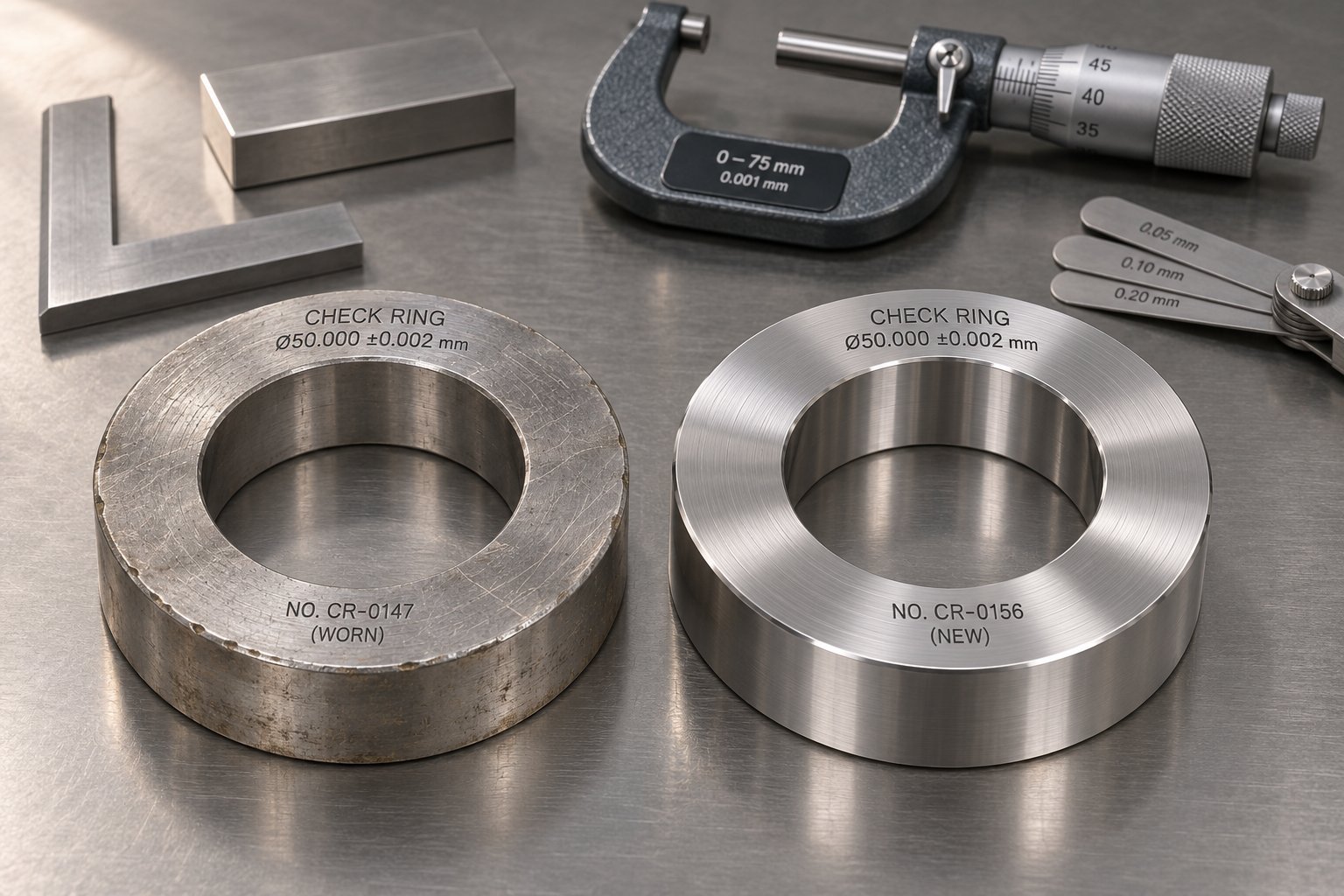
When to Rebuild and When to Replace a Check Ring Assembly
Data from diagnostic tests tells you something is wrong. Physical inspection tells you what is wrong. But neither one automatically tells you the right next move. Do you swap just the ring and rear seat, reinstall the screw tip, and get back into production? Or does the entire assembly need to go? The rebuild vs replace check ring assembly decision is one of the most practical — and most frequently guessed at — calls a maintenance team makes. Getting it right saves money and downtime. Getting it wrong means pulling the screw again in a few weeks because the "repaired" assembly still cannot hold a consistent seal.
Let's define the terms clearly. A rebuild means replacing only the worn component — typically the sliding ring, the rear seat, or both — while retaining the screw tip body because its geometry and threads remain within specification. A full replacement means installing an entirely new matched assembly: new screw tip, new check ring, and new rear seat, manufactured as a set to guarantee dimensional compatibility across all mating surfaces.
Measurable Wear Indicators for Decision-Making
Gut feeling is not a measurement method. The rebuild-or-replace decision should be driven by specific, quantifiable check ring wear indicators in injection molding — each one measured against defined thresholds that separate "still serviceable" from "replace now." Four indicators matter most:
- Ring OD wear relative to original dimension — The outer diameter determines the radial seal against the barrel bore. Measure with a calibrated outside micrometer at multiple points around the circumference and along the ring's length. Uneven readings indicate localized wear or barrel misalignment — a problem that persists even with a new ring if the root cause is not corrected.
- Sealing-face surface condition — The rear face of the ring and the mating face of the rear seat must be smooth, flat, and free of defects to form an effective axial seal. Scoring, galling, erosion channels, or pitting on either surface creates micro-leakage paths that no amount of injection pressure can overcome.
- Rear seat flatness and surface finish — Beyond visible defects, the seat surface must remain geometrically flat across its full sealing width. A seat that has dished, cupped, or developed a concave profile from repeated ring impact no longer distributes sealing force evenly.
- Screw tip geometry integrity — The tip body provides the sliding surface for the ring and the thread engagement with the screw. Wear grooves on the tip's outer surface cause the ring to hang up during travel. Thread damage compromises the assembly's structural rigidity under injection pressure.
The following table provides specific criteria for each indicator, separating mild wear that a rebuild can address from severe degradation that demands full replacement:
| Wear Indicator | Rebuild Candidate (Mild Wear) | Replace Required (Severe Wear) | Measurement Method |
|---|---|---|---|
| Ring OD Wear | Uniform diameter reduction within 0.002-0.004 inches of original spec; even wear pattern around circumference | Diameter reduced more than 0.005 inches below original spec; uneven or localized wear exceeding 0.002 inches variance around circumference | Outside micrometer at 3+ circumferential positions and 2+ axial positions; compare to original drawing or OEM specification |
| Sealing-Face Surface Condition | Light, uniform polishing marks; minor circumferential scratches that cannot be felt with a fingernail; no visible pitting or erosion channels | Deep scoring or grooves detectable by fingernail; visible pitting from corrosion; galling (material transfer) between ring and seat surfaces; erosion channels cut into the sealing band | Visual inspection under magnification; fingernail drag test across sealing face; surface roughness measurement with a profilometer if available |
| Rear Seat Flatness | Flat contact verified by light blue (Prussian blue) or marker test showing 80%+ continuous contact band across sealing width | Dished, cupped, or concave profile visible in marking test; contact concentrated in narrow band or broken into discontinuous patches covering less than 60% of sealing width | Prussian blue or marking compound applied to ring face, pressed against seat; evaluate contact pattern for coverage and uniformity |
| Screw Tip Geometry | Sliding surfaces smooth with no perceptible grooves; threads clean with no deformation; taper profile matches original geometry | Visible wear grooves on the OD where ring travels; thread galling, cross-threading, or deformation; taper worn enough to alter ring travel distance or front seat contact | Visual and tactile inspection of sliding surfaces; thread gauge check; compare taper profile to drawing or new reference component |
When a Rebuild Restores Performance and When It Cannot
A rebuild makes sense when the damage is isolated. If the ring's OD has worn slightly undersized but the rear seat face is still flat, smooth, and within tolerance — and the screw tip slides freely with no grooves — then swapping just the ring restores the assembly to functional condition at a fraction of full replacement cost. The same logic applies if the rear seat has developed light scoring while the ring and tip remain healthy: replace the seat alone and you are back in business.
A rebuild fails when multiple components have degraded simultaneously, or when one component's wear has damaged its mating partner beyond recovery. A deeply scored rear seat almost always means the ring that wore against it is also compromised — the scoring pattern on the seat mirrors the condition of the ring face that created it. Replacing only one half of that worn pair leaves the new component mating against a damaged surface, accelerating its own wear and recreating the leakage problem in short order.
Here is the critical check that ties physical inspection back to the diagnostic tests covered earlier: if the assembly fails cushion consistency, pressure decay, or short-shot progression testing even after a rebuild, full replacement is warranted regardless of what the dimensional measurements suggest. Measurements capture geometry. Tests capture function. A ring can measure within tolerance and still perform unacceptably because surface micro-damage — invisible to a micrometer — disrupts the seal under injection pressure. Trust the test data over the calipers when the two disagree.
Planning Replacement Intervals and Sourcing Components
Reactive replacement — pulling the screw only after quality has already collapsed — is the most expensive maintenance strategy in injection molding. A smarter approach is to plan your check ring replacement interval based on two variables that your production data already tracks: resin abrasiveness and shot count.
For unfilled commodity resins processed at moderate conditions, check ring assemblies commonly deliver 1 to 2 million shots before sealing performance degrades noticeably. Glass-filled resins at 15-30% filler loading cut that interval dramatically — often to 250,000 to 500,000 shots depending on glass fiber length and ring material grade. Heavily filled compounds (30%+ glass) or ceramic-reinforced formulations can demand replacement after as few as 100,000 to 200,000 shots if the ring metallurgy is not upgraded to CPM steels or carbide.
These are not rigid numbers. Your actual interval depends on injection speed, pack pressure, barrel temperature, and — critically — the ring material's wear resistance relative to the resin being processed. Use the diagnostic tests on a quarterly cycle to track degradation trends and correlate the results with your shot counter. Over two or three replacement cycles, you will build a site-specific dataset that predicts when the next replacement will be needed with far more accuracy than any generic guideline.
Planning also means having the right replacement parts available before the machine goes down. This is where documentation-driven sourcing pays its biggest dividend. The dimensional records, worn samples, and process data you collected during previous inspections give a qualified supplier everything needed to manufacture the correct component without guesswork or trial-and-error fitment.
Suppliers who support this workflow — accepting drawings, worn samples, photographs, and measured dimensions as inputs for quoting and manufacturing — deliver more reliable results than vendors limited to catalog part numbers. NANHAIYA is one example of this approach in practice. Their product range covers check rings, screw tips, non-return valves, injection nozzles, and thermocouples — the core components of a check ring assembly and its surrounding injection unit — and their team reviews machine details, drawings, worn samples, photos, and dimensions to assess compatibility and manufacturing feasibility before committing to a quote. That level of engagement is exactly what documentation-driven sourcing looks like: the supplier understands your specific assembly before metal is cut, reducing the risk of receiving a part that is close but not quite right.
The cost of a spare check ring assembly sitting on your maintenance shelf is always less than the cost of a production line sitting idle while you wait for one to arrive.
Stock critical spares for your highest-utilization machines. Track shot counts against your site-specific wear data. Run diagnostic tests on a defined schedule and record the trends. When the numbers tell you replacement is approaching, the parts are already in hand, the supplier relationship is already established, and the swap happens on your timeline — not on an emergency basis that disrupts production and multiplies cost. That discipline transforms the check ring from a chronic source of silent quality loss into a predictable, manageable maintenance line item.
Frequently Asked Questions About Check Ring Injection Molding
1. How do you test a check ring on an injection molding machine?
Three primary tests evaluate check ring performance. The cushion consistency test records screw position at transfer and end of hold across 20+ shots, flagging variation beyond +/-0.5 mm as a concern. The pressure decay test seals the nozzle, builds hold pressure, then monitors how quickly pressure bleeds off — rapid, erratic decay signals significant backflow. The short-shot progression test weighs 10-20 deliberately short parts at identical settings; shot weight variation above 2-3% indicates inconsistent ring closure. Running all three tests quarterly as part of preventive maintenance catches degradation well before defects appear on molded parts.
2. What causes a check ring to fail in injection molding?
Check ring failure stems from several interacting factors. Abrasive resins containing glass or mineral fillers erode the ring OD and sealing faces, widening clearances that allow backflow. Corrosive resins like PVC and acetals chemically pit sealing surfaces, destroying the smooth finish needed for a tight seal. Carbon buildup or degraded resin trapped between sliding surfaces causes intermittent sticking, leading to erratic closure timing. Mismatched metallurgy — such as using standard H-13 tool steel with heavily glass-filled compounds — dramatically accelerates wear. Even barrel bore enlargement undermines the radial seal, making a new ring ineffective if the barrel itself is worn.
3. What is the difference between a sliding ring and a locking ring check valve?
A sliding ring floats freely between the screw tip and rear seat, relying solely on melt pressure differentials to open and close. It offers easy maintenance, fast color changes, lower cost, and minimal barrel wear since it does not rotate with the screw. A locking ring interlocks with the screw tip and rotates during plasticating, using mechanical features to provide faster, more repeatable closure. However, locking rings can score the barrel bore, trap residual material during color changes, and cost more to maintain. Sliding rings suit general-purpose molding, while locking rings excel in precision medical and optical applications where minimal shot-to-shot variation is critical.
4. How often should a check ring be replaced in injection molding?
Replacement intervals vary widely based on resin abrasiveness and ring material. Unfilled commodity resins typically allow 1-2 million shots before noticeable seal degradation. Glass-filled resins at 15-30% loading shorten that to roughly 250,000-500,000 shots, while heavily filled compounds above 30% glass may demand replacement every 100,000-200,000 shots unless premium CPM steels or carbide rings are used. Rather than relying on generic guidelines, track diagnostic test results against your shot counter over two or three replacement cycles to build site-specific data that accurately predicts when each machine needs service.
5. Should you rebuild or fully replace a worn check ring assembly?
A rebuild — swapping only the worn ring or rear seat while keeping the screw tip — makes sense when damage is isolated to one component and the remaining parts measure within specification with smooth, undamaged sealing surfaces. Full replacement is warranted when multiple components show simultaneous degradation, when deep scoring or galling has damaged mating surfaces, or when the assembly fails diagnostic performance tests even after a partial rebuild. Suppliers like NANHAIYA review worn samples, photos, and measured dimensions to assess whether a single replacement component or a complete matched assembly is the correct solution, helping maintenance teams avoid repeat failures from mismatched parts.
Written by
Nanhaiya Technical Team
Zhoushan Nanhaiya Plastic Machinery Co., Ltd.
The Nanhaiya technical team supports screw and barrel manufacturing projects through application review, technical communication, custom manufacturing coordination, and production and quality control.
Discuss Your Application
Related Articles
More insights on screw barrel technology and plastics processing.
Injection Molding Color Mixing: From Streaks to Flawless Consistency
Nov 19, 2026
Master injection molding color mixing with expert guidance on colorant types, screw design, process parameters, defect troubleshooting, and Delta E QC protocols.
Read Article
Wrong Extruder Breaker Plate? Spot the Signs Before Scrap Piles Up
Nov 19, 2026
Learn how to select, size, and maintain your extruder breaker plate. Covers hole geometry, pressure drop, polymer-specific specs, and troubleshooting tips.
Read Article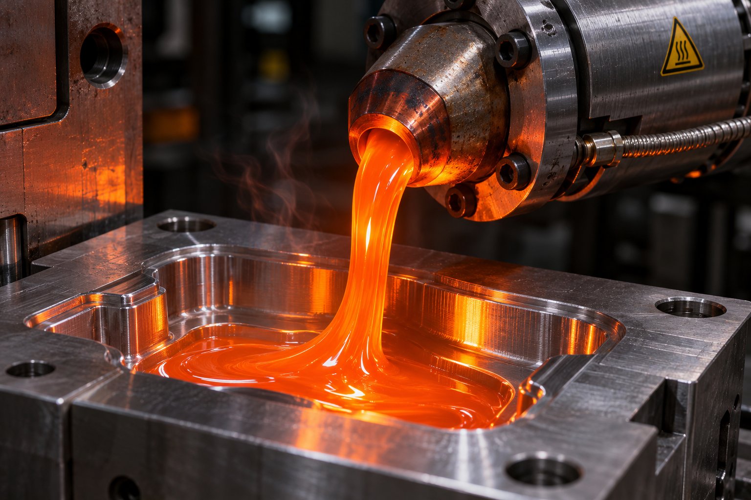
Injection Molding Melt Temperature: Why Your Barrel Settings Lie
Nov 19, 2026
Learn why barrel set points lie about injection molding melt temperature. Complete resin chart, measurement methods, defect troubleshooting, and optimization steps.
Read ArticleLooking for something else?
Search by material, symptom or product and jump straight to the relevant page.
These are navigation suggestions based on keyword matching — not a quotation, not a delivery commitment, and not a substitute for engineering review. Final specification is confirmed by our engineers against your drawings and processed material.
Need help with screw barrel selection?
Share your machine model, processed material and application. Our team can help with pricing and technical support.