

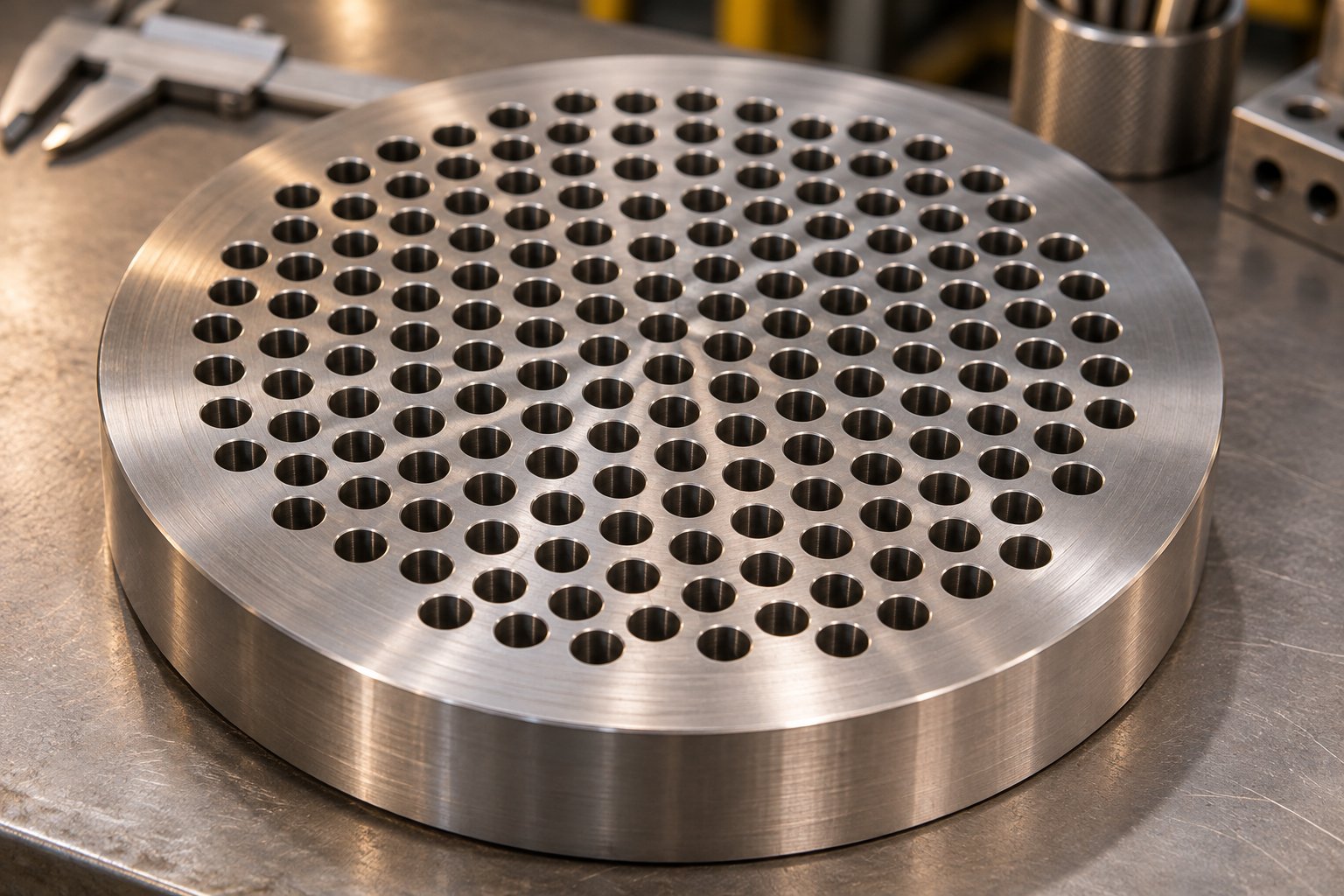
What an Extruder Breaker Plate Does and Why It Matters
Picture the discharge end of your extruder barrel. Molten polymer is spiraling forward under immense pressure, carrying the rotational memory of the screw flights. What stands between that chaotic, swirling melt and a clean die entry? A single, precisely engineered disc riddled with holes — the extruder breaker plate.
An extruder breaker plate is a thick, perforated metal disc installed between the screw tip and the die assembly. It performs three core functions: supporting the screen pack for melt filtration, converting rotational melt flow into straight linear flow, and generating controlled back pressure that improves melt homogeneity.
That definition sounds simple enough. Yet this component is far from passive — it actively shapes every kilogram of polymer that leaves your barrel.
Definition and Core Functions
Filtration support. Fine wire mesh screens, known collectively as the screen pack, trap contaminants like unmolten gels, metal shavings, and degraded polymer particles. Those delicate mesh layers would buckle instantly under typical extrusion pressures without a rigid backstop. The breaker plate in an extruder provides exactly that structural reinforcement, holding the screen pack firmly in place even under peak operating loads.
Flow straightening. As polymer travels along the spinning screw flights, it picks up a helical velocity pattern. If that swirling melt enters the die directly, you'll see warpage, surface distortion, and uneven wall thickness in the finished product. The dense hole pattern of the plate forces the melt to split into dozens — sometimes hundreds — of small parallel streams. By the time those streams recombine downstream, the rotational component is effectively eliminated, and the melt moves in a uniform, axial direction toward the die.
Back-pressure generation. Every extrusion process needs a controlled level of resistance at the barrel's discharge end. The restrictive hole pattern creates that resistance, raising internal barrel pressure and intensifying the shear-mixing action between the screw flights. The payoff is a more thermally and compositionally homogeneous melt — which translates directly into consistent product quality.
Where the Breaker Plate Sits in the Barrel Assembly
Physically, the plate is bolted or clamped at the very end of the barrel, seated just upstream of the die adapter. One or more layers of wire mesh screen sit against its upstream face, sandwiched between the advancing melt and the plate itself. Together, this screen-and-plate assembly acts as the final checkpoint before polymer enters the shaping tool.
In single-screw extruders, the breaker plate is especially critical. A single screw lacks the intermeshing geometry that twin-screw designs use to naturally disrupt rotational flow. Without a well-matched plate, a single-screw system would push spiraling, poorly mixed melt straight into the die. Twin-screw extruders still use breaker plates for filtration support and pressure control, but their self-wiping, intermeshing screws already handle much of the flow-straightening work independently.
This distinction matters because it means plate selection, hole geometry, and open area all carry different weight depending on your extruder type — a nuance that becomes even more important when you consider how the plate interacts with every other component in the extrusion system.
How the Breaker Plate Connects to the Full Extrusion System
Think of your extrusion line as a chain. The screw melts and pushes, the breaker plate conditions and filters, and the die shapes the final product. Weak links anywhere show up at the end of the line — but the breaker plate extruder interface is uniquely influential because it sits at the handoff point between melt generation and melt shaping. Treating it in isolation is a mistake that leads to mismatched specifications and hard-to-diagnose quality problems.
Interaction With the Screw and Barrel
The breaker plate creates a pressure seal at the barrel's discharge end. That seal does more than just hold the screen pack in place — it establishes the back-pressure environment the screw needs to work efficiently. Here is why that matters: as the screw rotates, it develops a pressure gradient that drives polymer forward. The resistance created by the plate and screen pack directly determines how much of that developed pressure translates into useful conveying force versus how much energy converts to frictional heat inside the melt.
Imagine turning up the restriction by installing a plate with smaller holes or lower open area. Barrel pressure climbs, the screw works harder against the increased resistance, and melt temperature rises from the added shear. In some cases that extra mixing energy is exactly what you want — especially with a shallow-flighted screw processing a material that needs intensive homogenization. In others, it pushes a heat-sensitive polymer dangerously close to degradation.
This is precisely why screw design parameters — compression ratio, flight depth, channel geometry — must be considered alongside extruder breaker plate design choices like hole diameter and open area percentage. A high-compression screw paired with a restrictive plate can create excessive shear heating. A low-compression screw paired with wide-open holes may not generate enough back pressure to produce a well-mixed melt. The two components are tuned as a system, not independently.
In single-screw extruders, this relationship is especially critical. Without intermeshing geometry to mechanically break up rotational flow and force dispersive mixing, the breaker plate is often the single most important element controlling melt uniformity at the barrel exit. Twin-screw systems still rely on the plate for filtration support and pressure regulation, but their self-wiping screw elements already provide substantial mixing action upstream.
Impact on Die and Downstream Equipment
What happens at the breaker plate does not stay at the breaker plate. The flow-straightening effect — splitting spiraling melt into parallel axial streams — directly shapes the velocity profile entering the die adapter. A well-matched plate delivers a symmetrical, even melt front. A worn or poorly selected one sends an unbalanced flow distribution into the die, and from there, the problems cascade quickly.
You'll notice the effects in the finished product: thickness variation across a sheet or film, visible surface streaks from velocity mismatches at the die lips, or subtle warpage caused by residual stress differences linked to non-uniform melt temperature. These defects are frequently blamed on die design or downstream cooling, but the root cause often traces back to the plate.
A poorly seated or partially blocked plate can also create localized dead spots where polymer stagnates, degrades, and eventually releases as black specks or gels — contamination that no amount of downstream trimming will fix.
To keep the full picture in view, here are the key system interactions the breaker plate influences:
- Screw back-pressure feedback — regulates conveying efficiency and energy input upstream of the plate
- Melt temperature contribution — shear through the holes adds thermal energy that must be accounted for in the overall heat balance
- Screen-pack support — provides the rigid backing that keeps filtration media intact under operating pressure
- Flow-profile conditioning — eliminates rotational flow and establishes the symmetrical melt front the die requires
- Contaminant filtration — works in tandem with the screen pack to remove gels, degraded material, and foreign particles before the melt enters the shaping tool
Every one of these interactions changes when you swap hole patterns, adjust open area, or let wear go unchecked. That interconnectedness is exactly why understanding the specific geometry options available — and how each one shifts pressure drop, shear, and flow distribution — is essential for making the right selection.
Breaker Plate Hole Patterns and Geometry Explained
Hole count and plate diameter grab most of the attention during extruder breaker plate selection — but the shape of each individual hole quietly dictates how polymer behaves as it passes through. Two plates can share identical open area percentages yet produce dramatically different pressure drops, shear heating profiles, and dead-spot tendencies simply because their hole geometries differ. Understanding those differences is the key to matching a plate to your process rather than just your barrel.
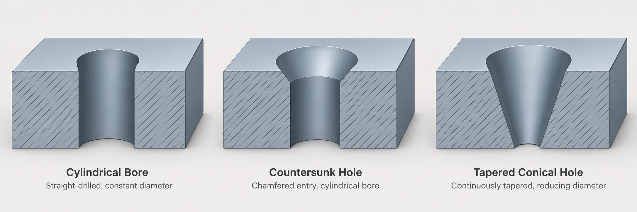
Straight-Drilled, Countersunk, and Tapered Hole Geometries
Straight-drilled holes are the simplest and most common design. Each perforation has a uniform diameter from the upstream face all the way through to the downstream exit. The melt encounters a sharp entry edge and a sharp exit edge, which creates localized shear spikes at both transitions. For many commodity applications on a single screw extruder breaker plate setup, straight-drilled holes work perfectly well — they are inexpensive to machine, easy to inspect, and straightforward to clean. The trade-off? Those sharp edges generate the highest shear heating of any geometry, and the abrupt entry can create small stagnation zones at the upstream face where melt circulation slows.
Countersunk holes add a chamfered or wider-diameter entry on the upstream side of the plate. Imagine a funnel gently guiding polymer into each hole rather than forcing it through a hard 90-degree corner. That chamfer does two things simultaneously: it reduces entry shear by easing the melt into the restricted channel, and it provides a smoother seat for the screen pack and breaker plate in the extruder barrel assembly. The screen mesh nests into the countersunk recess, distributing pressure more evenly and extending mesh life. Countersunk designs are a smart upgrade whenever you process shear-sensitive polymers or run fine-mesh filtration that demands solid screen support.
Tapered or conical holes take streamlining a step further. Here, the bore narrows progressively from the upstream face toward the downstream exit. This geometry accelerates the melt smoothly, virtually eliminating the dead spots that plague straight-drilled plates. Because there are no abrupt diameter changes, shear heating is the lowest of the three types. Tapered holes are the preferred choice for heat-sensitive resins, long-residence-time processes, and any extruder setup for filled plastics breaker plate configurations where material hang-up can cause degradation or color contamination during changeovers. The downside is cost — conical bores require more complex machining, and inspecting a used extruder breaker plate with tapered holes for internal wear is trickier than checking a straight bore with calipers.
Hole Diameter and Open Area Percentage Engineering
Geometry is only half the equation. The size and quantity of holes determine how much of the plate face is actually available for melt flow — a value known as the open area percentage.
The calculation itself is simple: divide the total combined area of all holes by the total face area of the plate, then multiply by 100 to express the result as a percentage. For round holes in a straight pitch pattern, the formula becomes:
Open Area (%) = (D² × 78.54) / C², where D is the hole diameter and C is the center-to-center pitch between adjacent holes.
Industry practice typically targets an open area between 30 and 40 percent with hole diameters in the 4 to 8 mm range. But where you land within those ranges depends entirely on what you are processing and what you need the plate to do.
Lower open area and smaller holes — say 30 percent with 4 mm bores — generate higher back pressure and finer effective filtration. This end of the spectrum suits shear-sensitive materials, applications demanding tight melt-temperature uniformity, and lines running screen packs that need maximum contaminant capture. The penalty is a larger pressure drop across the assembly and more shear-generated heat.
Higher open area and larger holes — approaching 40 percent with 6 to 8 mm bores — minimize pressure drop and shear heating. High-throughput lines processing clean, low-viscosity melts benefit most. You'll also lean toward this end when running a single screw extruder breaker plate on a low-compression screw, where excessive restriction would starve the die of adequate flow.
The comparison table below maps each hole geometry against the performance characteristics that matter most during selection:
| Geometry Type | Pressure Drop Impact | Shear Heating Effect | Dead-Spot Risk | Best-Use Applications |
|---|---|---|---|---|
| Straight-Drilled | Moderate — uniform restriction through full plate thickness | Highest — sharp entry and exit edges create localized shear spikes | Moderate — stagnation possible at upstream face corners | Commodity polyolefins, general-purpose extrusion, cost-sensitive lines |
| Countersunk | Slightly lower — chamfered entry reduces entry-side restriction | Moderate — smooth entry lowers upstream shear while exit remains sharp | Low to moderate — funnel entry improves upstream flow pattern | Shear-sensitive resins, fine screen pack support, PVC processing |
| Tapered / Conical | Lowest — progressive narrowing distributes pressure drop evenly | Lowest — no abrupt diameter transitions, minimal localized heating | Lowest — accelerating flow sweeps material through without stagnation | Engineering plastics, filled compounds, color-change-sensitive lines, heat-sensitive polymers |
Choosing the right combination of geometry, diameter, and open area is never a one-size-fits-all decision. The polymer you are processing — its viscosity, thermal sensitivity, filler content, and contamination profile — shifts the ideal specification significantly. That material-driven perspective is where selection truly gets interesting, especially once you start comparing how commodity resins, engineering plastics, and recycled feedstocks each push the plate toward very different design targets.
Sizing Breaker Plates by Extruder Barrel Diameter
Geometry and open area tell you how a plate manages melt flow. But none of that matters if the plate does not physically fit your machine or withstand your operating pressure. Matching extruder breaker plate dimensions to your specific barrel size is the foundation every other selection decision builds on — yet it is one of the most poorly documented aspects of extrusion setup.
Matching Plate Diameter and Thickness to Barrel Size
The outer diameter of the plate must seat precisely in the barrel bore or adapter housing. Even a fraction of a millimeter of play allows melt to bypass the screen pack entirely, creating unfiltered channels that defeat the purpose of filtration and pressure control. Most plates are machined to a close sliding fit within the barrel recess, with the sealing rim ground flat to prevent polymer leakage under pressure.
Thickness, on the other hand, is driven primarily by operating pressure. Imagine a thin plate subjected to 350 bar of melt pressure concentrated over the screen pack area — it will flex, bow, or even crack. A thicker plate resists that deflection but adds to the overall pressure drop and increases the thermal residence time of polymer inside the holes. You are always balancing mechanical strength against flow efficiency.
How does this play out in practice? Operating pressures in typical extrusion processes span roughly 100 to 400 bar. At the low end — flexible PVC or LDPE running at moderate output rates — a thinner plate with generous open area handles the load comfortably. At the upper end — engineering plastics like nylon or PEEK, heavily filled compounds, or high-output lines pushing commodity resins hard — breaker plate thickness for the extruder must increase significantly to prevent mechanical failure. Glass-filled nylon at 300+ bar, for example, demands a plate noticeably thicker than what you would use for the same barrel diameter running unfilled polyethylene at 150 bar.
Temperature plays a supporting role too. Sustained operation above 300 degrees Celsius weakens most carbon steels, so high-temperature applications often call for both greater thickness and upgraded alloy grades. The sizing decision is never just about diameter — it is a three-way conversation between bore fit, pressure rating, and thermal environment.
Breaker Plate Specifications by Barrel Diameter
Finding reliable, size-specific guidance in one place is surprisingly difficult. Equipment manuals rarely go beyond listing a part number, and generic advice like "use 3 to 7 mm holes" leaves too much room for error. The reference table below consolidates typical specification ranges across common extruder sizes, drawn from general engineering practice and industry guidance on breaker plate selection factors. Use it as a starting point — then verify against your specific machine drawing and operating conditions.
| Barrel Diameter (mm) | Typical Plate Thickness (mm) | Recommended Hole Diameter (mm) | Approximate Open Area Target (%) | Common Screen Pack Configuration |
|---|---|---|---|---|
| 25 – 30 | 10 – 15 | 2 – 3 | 30 – 35 | 20 / 60 / 20 mesh or 20 / 80 / 20 mesh |
| 35 – 45 | 12 – 18 | 2.5 – 4 | 30 – 38 | 20 / 60 / 100 / 20 mesh |
| 50 – 65 | 15 – 22 | 3 – 5 | 32 – 40 | 20 / 40 / 80 / 40 / 20 mesh |
| 75 – 90 | 18 – 28 | 4 – 6 | 33 – 42 | 20 / 40 / 100 / 40 / 20 mesh |
| 100 – 120 | 22 – 35 | 4 – 7 | 35 – 45 | 20 / 40 / 80 / 120 / 40 / 20 mesh |
| 130 – 150 | 28 – 40 | 5 – 8 | 35 – 48 | 20 / 40 / 80 / 120 / 40 / 20 mesh |
A few patterns stand out in the data. Plate thickness roughly scales with barrel diameter, but the relationship is not linear — larger barrels handle proportionally higher throughput and melt force, so thickness grows faster than a simple ratio would suggest. Hole diameters follow a similar trend, with smaller extruders in the 25 to 45 mm range often using 2 to 4 mm holes, while machines above 100 mm can accommodate 7 or 8 mm bores without sacrificing adequate back pressure at typical output rates.
Open area targets also creep upward as barrel size increases. Why? Larger-diameter plates have more total face area available, and the higher volumetric throughput of big extruders demands lower flow restriction per unit area to avoid excessive pressure drop. A 150 mm extruder running at full capacity through a plate with only 30 percent open area would generate a punishing pressure spike and drive melt temperatures well above target.
Screen pack configurations grow more complex on bigger machines too. Small lab or pilot extruders often run two or three mesh layers, while production-scale lines above 75 mm commonly use four to six layers arranged in a coarse-to-fine-to-coarse sequence to balance filtration, pack life, and pressure drop. The coarse upstream layer protects finer media from rapid loading, while the coarse downstream layer supports the stack against the plate's hole pattern.
Always confirm breaker plate specifications against your extruder manufacturer's drawing and validated process setup — the table above provides representative ranges, not universal design rules.
Barrel diameter and thickness set the mechanical envelope. Hole geometry and open area define the flow behavior. But there is a third variable that shifts the entire selection calculus: the polymer itself. A plate perfectly sized for polyethylene may be a poor choice for PVC, and an outright liability for glass-filled nylon. Material-specific demands deserve their own close look.
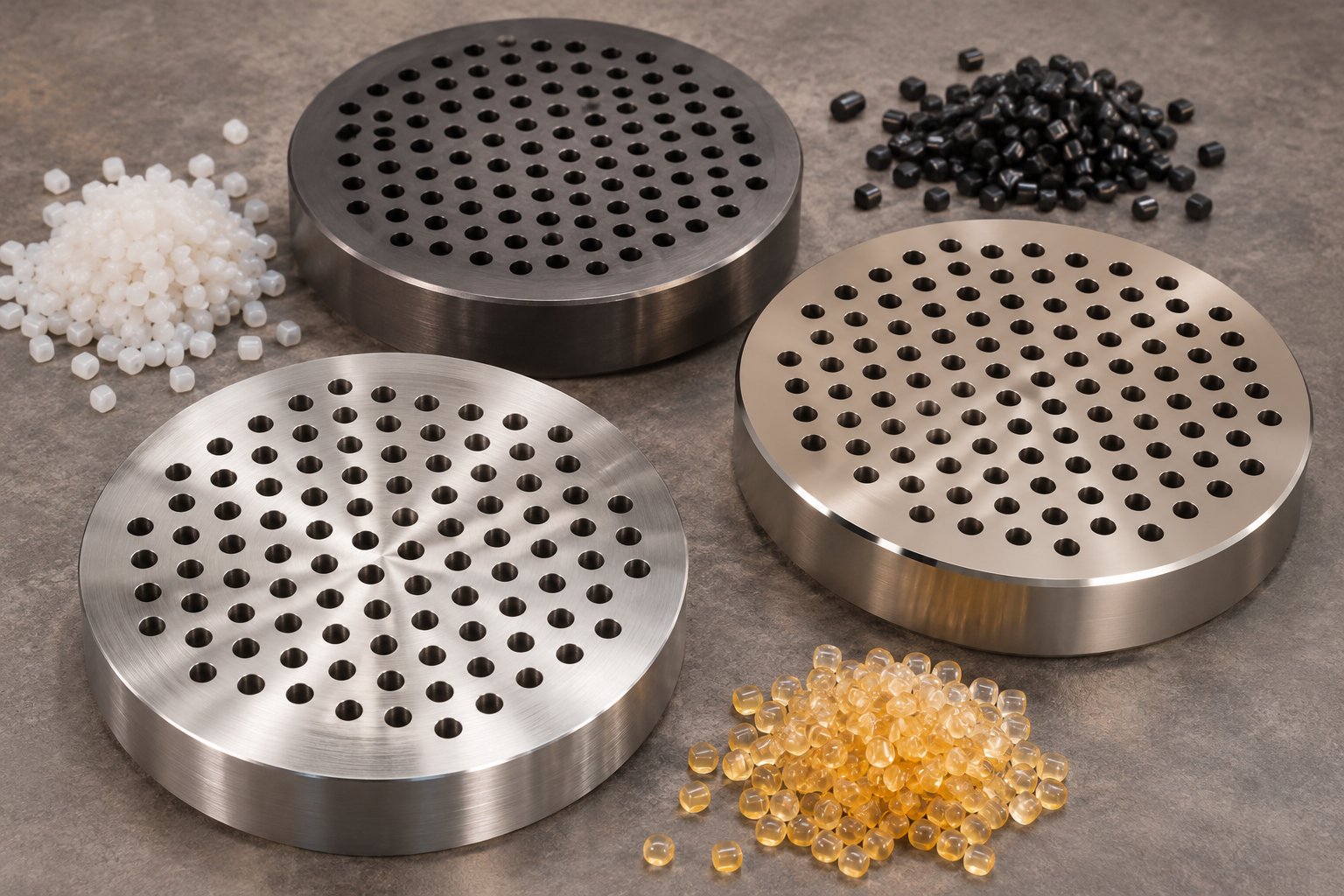
Polymer-Specific Breaker Plate Selection by Material Family
A breaker plate that performs flawlessly with polyethylene can corrode within days running PVC, and one rated for commodity resins may erode beyond tolerance in weeks processing glass-filled nylon. The polymer dictates the alloy, the hole geometry, the open area range, and how often you pull the plate for inspection. Ignoring that reality is one of the fastest paths to unexplained scrap.
Polyolefins, PVC, and Commodity Resins
Polyolefins — polyethylene and polypropylene — are the most forgiving material family. They process at moderate temperatures, generate no corrosive byproducts, and typically carry low filler loads. A standard carbon-steel plate with straight-drilled holes and a moderate open area in the 33 to 40 percent range handles most PE and PP applications without drama. Inspection intervals can be relatively relaxed unless you are running recycled polyolefin with abrasive contamination.
PVC is an entirely different conversation. During processing, PVC releases trace amounts of hydrochloric acid — an aggressive corrosive agent that attacks unprotected carbon steel surprisingly fast. A breaker plate for PVC extrusion must be manufactured from corrosion-resistant material: stainless steel (typically 316-grade) or, at minimum, a nickel-plated carbon steel surface. Beyond alloy selection, hole geometry matters more here than with polyolefins. PVC is notoriously sensitive to hang-up and thermal degradation. Any dead spot where material stagnates — a sharp-edged straight bore, an unpolished upstream face — becomes a site where polymer chars, discolors, and eventually breaks free as black specks in the extrudate. Countersunk or tapered holes with polished internal surfaces are strongly preferred, as noted in guidance for PVC and heat-sensitive compound processing. Open area can push toward the higher end of the range to minimize residence time inside the plate.
Engineering Plastics and Filled Compounds
Step up to engineering plastics — nylon (PA6, PA66), PET, polycarbonate, or PEEK — and thermal demands escalate sharply. Sustained barrel temperatures above 280 degrees Celsius are routine, and some PEEK formulations push past 380 degrees. Standard carbon-steel plates lose mechanical strength in that environment. Breaker plate material selection for engineering plastics shifts toward hardened tool steels, H13-grade hot-work steels, or specialty nickel-based alloys that maintain hardness and dimensional stability at elevated temperatures. Tapered hole geometries help here too, because engineering plastics tend to have higher viscosity and longer relaxation times — conditions where dead-spot degradation shows up quickly as gels or discoloration.
Filled and reinforced compounds introduce a different threat: abrasion. Glass fibers, mineral fillers, and carbon fiber reinforcements act like liquid sandpaper flowing through every hole in the plate. An extruder breaker plate for glass-filled compounds can show measurable hole enlargement in as little as two to four weeks of continuous production. That erosion is not cosmetic — enlarged holes reduce back pressure, shift the flow distribution, and compromise filtration effectiveness without any obvious external signal. Hardened steel plates, nitrided surfaces, or stellite-coated hole edges dramatically extend service life but require tighter dimensional inspection schedules to catch wear before it affects product quality.
Recycled and regrind feedstocks deserve special attention because they combine multiple challenges simultaneously. A breaker plate for recycled plastic extrusion must handle variable contamination levels — paper fibers, metal fragments, mixed polymer species, degraded char — that change from lot to lot. Finer screen packs are usually necessary, which means more frequent pressure buildup and more frequent plate inspections for screen-abrasion damage on the upstream face. Recycled material can load screens much faster than virgin pellets, turning a routine weekly screen change into a daily or even per-shift task. The plate itself needs corrosion resistance (mixed-polymer recyclate often contains PVC contamination) and robust hole-edge hardness to withstand accelerated wear.
The list below maps each material family to its key breaker plate requirements — a quick-reference guide for matching your plate specification to your polymer:
- Polyolefins (PE, PP): Carbon steel acceptable; straight-drilled holes sufficient; 33–40% open area; standard inspection intervals (monthly or at scheduled shutdowns)
- PVC: Stainless steel or nickel-plated required; countersunk or tapered holes preferred; 35–45% open area to reduce residence time; inspect for corrosion pitting every screen change
- Engineering plastics (PA, PET, PC, PEEK): Hardened tool steel or nickel alloy; tapered holes recommended; 30–38% open area; inspect for thermal fatigue and dimensional stability at each maintenance cycle
- Glass-filled and mineral-filled compounds: Hardened or surface-treated steel (nitrided, stellite-coated); any geometry with hardened hole edges; 32–40% open area; measure hole diameters every two to four weeks
- Recycled and regrind material: Stainless or corrosion-resistant alloy; countersunk holes for easier cleaning; 35–42% open area; inspect upstream face for screen-abrasion grooving at every screen change
Each of these material-driven specifications shifts the pressure drop across the plate in a different direction. A corrosion-resistant plate with tapered holes and generous open area for PVC creates a very different pressure profile than a hardened, tighter plate for glass-filled nylon. Understanding how those pressure differences ripple through the entire extrusion system — and how to estimate them before problems appear on the production floor — is where the engineering gets genuinely practical.
Understanding Pressure Drop Across the Breaker Plate Assembly
You have matched your plate alloy to the polymer and selected a hole geometry that minimizes dead spots. The next question every process engineer asks is deceptively simple: how much pressure does this assembly actually consume? Getting that answer wrong — in either direction — costs you money. Too little restriction and melt homogeneity suffers. Too much and you waste drive energy, overheat the polymer, and shorten component life. A solid grasp of breaker plate pressure drop calculation principles puts you in control of that balance.
Factors That Influence Pressure Drop
Five variables dominate the pressure drop across any screen pack and breaker plate combination. Change any one and the entire pressure profile shifts:
- Number and diameter of holes — More holes and larger bores mean more total flow area, which lowers the velocity of melt through each channel and reduces frictional resistance. Fewer, smaller holes do the opposite.
- Plate thickness — A thicker plate extends the length of each flow channel. Polymer spends more time under shear inside the bore, and the pressure required to push it through increases proportionally.
- Open area percentage — This is the combined effect of hole count and diameter expressed as a fraction of the total plate face. Higher open area means lower restriction; lower open area means the melt is being squeezed through a smaller effective passage.
- Melt viscosity — A high-viscosity polymer like HDPE or unfilled nylon resists flow more aggressively than a low-viscosity LDPE or plasticized PVC at the same throughput. Viscosity is the single largest material-side driver of pressure drop.
- Throughput rate — Push more kilograms per hour through the same plate, and melt velocity through the holes climbs. Pressure drop rises with it — not linearly for most polymer melts, but steeply enough that a 20 percent output increase can produce a noticeably larger pressure jump.
The relationships are intuitive once you see the pattern. Smaller holes and thicker plates increase pressure drop. Higher open area reduces it. More viscous polymers at any given throughput see proportionally greater resistance. These are the levers you pull during extrusion setup, and the extruder breaker plate open area is often the easiest one to adjust because it only requires swapping a single component.
Here is why this matters in real numbers: operating pressures in typical extrusion processes range from roughly 100 to 400 bar. The breaker plate and screen pack assembly typically accounts for a significant share of that total system pressure drop — sometimes 15 to 30 percent or more, depending on screen fineness and plate geometry. That makes the plate one of the most adjustable variables in the entire extrusion setup. A die change is expensive and slow. A screw swap requires a full teardown. Switching to a plate with different open area or hole diameter? That can happen during a routine screen change.
Practical Pressure Drop Estimation
You do not need a rheology lab to get a useful estimate. The general approach follows three steps:
- Calculate total open area. Count the holes, determine each hole's cross-sectional area (pi times radius squared), and multiply by the number of holes. This gives you the total passage area available for melt flow.
- Estimate average melt velocity through the holes. Divide your volumetric throughput rate by the total open area. The result is the average speed at which polymer travels through each bore — the higher this velocity, the greater the frictional resistance.
- Apply a simplified pressure-drop relationship. For a Newtonian approximation, pressure drop scales with viscosity, melt velocity, and the length-to-diameter ratio of each hole. Real polymer melts are shear-thinning, so actual pressure drop is typically somewhat lower than a Newtonian calculation predicts at high shear rates, but the estimate still gives you a reliable directional guide for comparing plate options.
The pressure drop across the screen pack and breaker plate also depends heavily on screen condition. A clean 20/40/80/40/20 mesh stack adds a predictable baseline restriction. As contaminants accumulate, that restriction climbs steadily — sometimes doubling or tripling the initial differential before a screen change is triggered. This is why trending pressure over time matters far more than any single snapshot reading.
Back pressure from the extruder breaker plate improves melt mixing and temperature uniformity, but excessive pressure drop wastes drive energy and risks melt degradation — the goal is controlled resistance, not maximum resistance.
That principle is worth anchoring in every operator's thinking. Industry guidance on extrusion optimization consistently emphasizes that while screen packs and breaker plates enhance mixing through controlled back pressure, screens eventually block and cause pressure to build beyond productive levels — requiring replacement before productivity and safety are compromised.
The most practical diagnostic tool you already have? The pressure gauge mounted upstream of the plate. Operators should monitor this reading as a primary indicator throughout every production run. A stable reading within the validated process window means the screen pack is clean and the plate is performing as expected. A gradually rising trend signals screen-pack loading — contaminants are accumulating, flow restriction is growing, and a screen change or breaker plate inspection is approaching. A sudden spike can indicate a ruptured screen layer, a contamination slug, or a catastrophic blockage that demands immediate attention.
Differential pressure — the difference between readings upstream and downstream of the plate assembly — is even more diagnostic. If upstream pressure rises while downstream pressure stays relatively steady, the growing gap points squarely at screen or plate restriction rather than a die or adapter issue. This simple comparison separates filtration problems from downstream flow-path problems in seconds, saving hours of misdirected troubleshooting.
Pressure data also reveals wear. A plate with eroded, bell-mouthed holes generates less back pressure than a new one at the same throughput. If your upstream gauge shows a gradual downward drift over weeks or months — despite consistent screen changes and stable operating conditions — the plate itself may be wearing out. That kind of slow degradation flies under the radar until product quality visibly suffers, which is exactly why systematic cleaning and dimensional inspection routines are essential safeguards against invisible melt-quality drift.
Cleaning Methods and Inspection Criteria for Breaker Plates
Pressure trends tell you when something is wrong. But keeping the plate in service-ready condition — and knowing precisely when it is not — requires a deliberate maintenance routine. Surprisingly few extrusion operations have one. Plates get pulled during screen changes, given a quick visual check, and slid back into the barrel without any structured evaluation. That approach works until it does not, and by then you are chasing gels, streaks, and dimensional drift that could have been prevented with a fifteen-minute inspection.
A solid breaker plate maintenance schedule for extrusion lines rests on two pillars: choosing the right cleaning method for the polymer residue you are dealing with, and applying consistent, measurable inspection criteria every time the plate comes out of the machine.
Cleaning Methods for Different Polymer Residues
Not all polymer residues respond to the same cleaning strategy. The resin family you are processing, the filler content, and even the degradation history of the buildup all influence which approach works best — and which ones risk damaging the plate itself. Here are the four primary extruder breaker plate cleaning methods, along with the situations where each one earns its place.
Burn-off ovens. This is the workhorse method for polyolefins and most commodity resins. The plate is placed inside a controlled-atmosphere oven that heats residue to the point where it decomposes to ash, leaving bare metal behind. Fluidized-bed systems from manufacturers like Accurate Thermal and Dinamec use heated aluminum oxide particles or silica sand to transfer heat evenly across every surface of the plate. The particles are not abrasive — they simply carry thermal energy gently and uniformly, which avoids the hot spots and warping risks that open-flame torches create. Cleaning cycles in modern fluidized beds typically run one to two hours, and automatic air-flow controls free operators to handle other tasks during the cycle. For PE, PP, PS, and ABS residues, burn-off ovens deliver consistent, hands-off results.
The catch? PVC residues and certain adhesive copolymers do not respond well to thermal cleaning. PVC chars rather than ashing cleanly, leaving a stubborn carbonized layer that bonds to the metal. Worse, heating PVC residue releases hydrochloric acid vapor that can corrode the plate and the oven chamber. If your line runs PVC, burn-off ovens should be reserved for the non-PVC components in your maintenance rotation.
Solvent or chemical baths. When thermal methods are off the table, chemical cleaning steps in. Alkaline baths, specialized polymer-dissolving solvents, or caustic solutions break down adhesive and chlorinated residues that char in burn-off ovens. Controlled cleaning processes offered by specialists like Carolina PEC emphasize preserving the plate's surface coatings and precision perforations — a critical consideration for nickel-plated PVC plates or plates with fine-hole patterns. The key is matching the solvent chemistry to the specific polymer residue without attacking the base metal or any protective surface treatment. Always verify chemical compatibility before immersing a coated or plated plate.
Ultrasonic cleaning. Imagine thousands of microscopic cavitation bubbles collapsing against every surface inside each hole simultaneously. That is how ultrasonic cleaners work — high-frequency sound waves create rapid pressure cycles in a heated cleaning bath, generating tiny implosions that dislodge residue from areas no brush or pick could reach. This method is ideal for fine-hole plates where mechanical tools risk deforming the bore geometry. Ultrasonic tanks with heated water and mild detergent clean small internal passages more thoroughly than manual methods, and the process is entirely non-contact — no abrasion, no scratching, no dimensional distortion. If you are processing engineering plastics or running tight-tolerance plates with holes under 3 mm, ultrasonic cleaning deserves serious consideration.
Mechanical cleaning. Sometimes the simplest approach is the right one — especially for quick turnarounds between production runs. Brass wire brushes, brass picks, and soft copper scrapers can remove surface-level buildup without gouging hardened steel. The operative word is brass. Steel tools on a precision-machined plate will score the sealing faces and deform hole edges, creating the exact kind of damage you are trying to prevent. Mechanical cleaning works well as a first pass before a more thorough thermal or chemical cycle, or as a standalone method for lightly soiled plates pulled during routine screen changes.
Recycled or filled compound residues often demand a combination approach — a burn-off cycle to remove the bulk polymer, followed by ultrasonic or chemical cleaning to address embedded mineral filler or carbonized contaminants lodged deep inside the holes. No single method handles every residue type, so knowing how to clean an extruder breaker plate effectively means keeping multiple options in your maintenance toolkit.
Inspection Criteria and Replacement Triggers
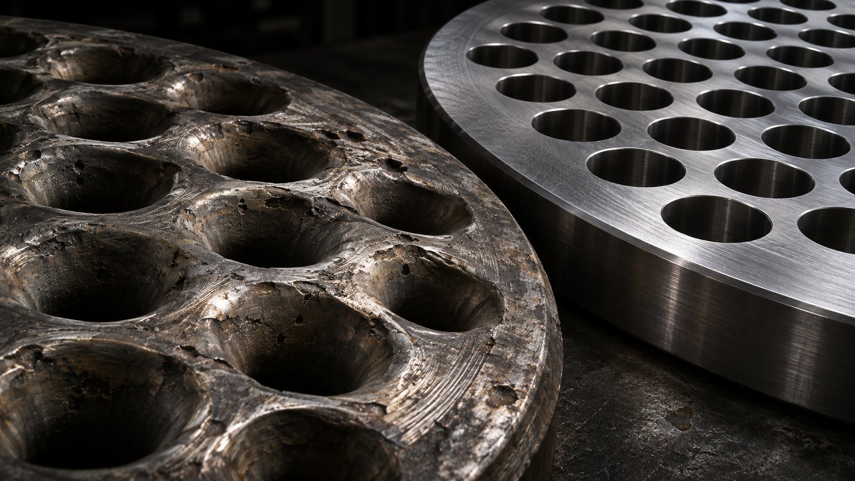
A clean plate is not necessarily a good plate. Cleaning reveals the true condition of the metal underneath, and that condition determines whether the plate goes back into service or gets retired. Vague visual checks are not enough. You need specific, measurable criteria — evaluated the same way every time — to catch wear before it silently degrades your melt quality.
Follow this breaker plate inspection and replacement checklist after every cleaning cycle:
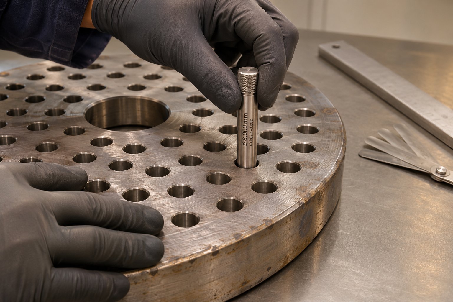
- Measure hole diameters at multiple points across the plate face. Use pin gauges or a calibrated caliper to check representative holes near the center, mid-radius, and outer ring. Filled compounds erode holes unevenly — center holes often wear faster because they carry a larger share of the melt flow. Any measurable enlargement beyond the original machining tolerance signals active erosive wear.
- Check plate flatness with a precision straight edge and feeler gauge. Lay the straight edge across the upstream face in at least two directions (typically 0 and 90 degrees). Warping — even a few hundredths of a millimeter — causes uneven screen pack sealing. Gaps between the plate face and the screen allow melt to bypass filtration in localized zones, creating unfiltered flow channels that defeat the purpose of the screen pack entirely.
- Inspect the upstream face for grooving or pitting. The screen pack sits directly against this surface under full melt pressure. Over hundreds of screen changes, the wire mesh abrades shallow grooves into the metal — particularly around the edges of the hole pattern where screen tension concentrates. Deep grooves compromise the seal and accelerate screen wear on subsequent installations.
- Examine the sealing rim for nicks, gouges, or compression damage. The outer rim creates the pressure seal between the plate and the barrel bore or adapter housing. Any damage here allows melt bypass around the entire plate perimeter — a failure mode that shows up as unexplained pressure loss and contamination in the extrudate even with a fresh screen pack.
- Verify that hole edges remain sharp and not bell-mouthed. Worn holes develop a funnel-shaped entry or exit — the telltale "bell-mouth" profile caused by abrasive fillers rounding off the sharp machined edge. Bell-mouthed holes reduce effective back pressure, alter the flow distribution, and can no longer support the screen pack uniformly. Once this profile is visible to the naked eye, the wear is already well advanced.
A plate showing measurable hole enlargement, face warping, or rim damage should be replaced rather than returned to service. Worn plates cause inconsistent back pressure and gradual melt-quality drift — problems that are difficult to diagnose because they develop slowly and mimic other issues like screw wear or die fouling. The cost of a replacement plate is trivial compared to the scrap, rework, and troubleshooting hours a worn one generates.
Worn breaker plates rarely fail in isolation. When inspection reveals significant erosion or warping, it is a strong signal to evaluate other barrel-end components that operate under the same conditions — screw tips, check rings, non-return valves, nozzles, and thermocouples all share the high-pressure, high-temperature environment at the discharge end. Replacing one worn part while ignoring its neighbors simply moves the weak link rather than eliminating it.
Maintenance teams benefit from identifying suppliers who cover multiple component categories and assess compatibility before quoting. For barrel-end items like screw tips, check rings, non-return valves, injection nozzles, and thermocouples, NANHAIYA's extruder spare parts catalog provides one starting point — their process involves reviewing machine details, drawings, worn samples, photos, and dimensions to verify fit and manufacturing feasibility before committing to production. Specialized items like breaker plates may be available on an inquiry basis. The broader principle holds regardless of which supplier you choose: any vendor willing to evaluate a worn sample or technical drawing before quoting is far more likely to deliver a part that actually fits your machine than one selling generic catalog dimensions.
A structured cleaning and inspection routine does more than extend plate life — it creates a paper trail. Recording hole measurements, flatness readings, and cleaning dates builds a wear-rate history specific to your materials and operating conditions. Over time, that data tells you exactly how many production hours or screen changes a plate can handle before reaching its replacement threshold. It transforms reactive maintenance into predictable scheduling, eliminating the surprise failures that cause unplanned downtime and unexplained quality excursions.
Of course, knowing when to replace a plate is only half the picture. The other half is recognizing the defects a worn or mismatched plate creates in your extrudate — and tracing those defects back to their root cause before the scrap bin fills up.
Troubleshooting Extrusion Defects Linked to the Breaker Plate
Here is a scenario that plays out in extrusion plants every week: surface streaks appear on a sheet line, and the first instinct is to adjust die lip bolts. Or dimensional variation creeps into a tubing run, and someone swaps the screw tip. Hours of downtime later, the real culprit turns out to be a worn breaker plate that nobody thought to pull and measure. Extrusion defects caused by the breaker plate are some of the most commonly misdiagnosed problems in the industry — largely because the plate sits out of sight, wedged between the barrel and the die adapter, easy to forget until the evidence becomes impossible to ignore.
This breaker plate troubleshooting guide maps the most frequent defects directly to their plate-related root causes, then walks through a systematic diagnosis sequence you can apply the next time quality drifts and the usual suspects come up clean.
Defects Caused by Worn or Incorrectly Sized Breaker Plates
Every defect tells a story. The trick is reading it correctly. A gel showing up in your extrudate points to a very different plate problem than a sudden spike in melt temperature or a slow drift in part dimensions. The table below connects five common defect categories to their most likely breaker plate causes — use it as your first filter before diving deeper into the process.
| Observed Defect | Likely Breaker Plate Cause | Why It Happens |
|---|---|---|
| Gels or unmolten particles in the extrudate | Oversized holes or excessive open area | Insufficient back pressure allows poorly mixed or incompletely melted polymer to pass through the screen pack and plate without adequate homogenization. The melt bypasses the mixing energy the screw was designed to deliver. |
| Surface streaks or flow lines | Damaged or unevenly worn hole pattern | When some holes are eroded wider than others — especially in an asymmetric pattern — melt velocity varies across the plate face. That non-uniform flow creates velocity mismatches at the die entry, which print directly onto the product surface as visible streaks or weld lines. |
| Excessive melt temperature | Too-small holes or too-low open area | Forcing polymer through an overly restrictive plate generates intense localized shear heating. The melt absorbs energy far beyond what barrel heaters contribute, pushing temperatures into the degradation range for heat-sensitive resins. General extrusion troubleshooting guidance confirms that shear from restrictive flow passages is a primary driver of unexpectedly high melt temperatures. |
| Pressure instability or surging | Partially blocked screen pack on a warped plate | A warped plate cannot seal the screen pack uniformly. Some zones load with contaminants faster than others, creating intermittent flow restriction that cycles between partial blockage and breakthrough. The pressure gauge reads this as erratic surging — the signature of extruder pressure surging that mimics screw wear or feed instability. |
| Dimensional variation in the extrudate | Asymmetric hole wear causing melt-flow maldistribution | When erosion concentrates on one side of the plate — common when filled compounds flow preferentially through certain regions — the die receives more material on that side. The result is wall-thickness variation in tubing, gauge bands in film, or cross-sectional asymmetry in profiles that no amount of die adjustment can fully correct. |
Notice a pattern? Every one of these defects can be — and frequently is — blamed on something else. Gels get attributed to poor resin quality. Streaks trigger die inspections. Temperature issues prompt barrel heater checks. Surging sends technicians after the screw and drive system. Dimensional drift leads to die bolt adjustments. The breaker plate rarely makes the initial suspect list, which is exactly why breaker plate wear symptoms in extrusion persist far longer than they should.
Systematic Diagnosis Steps
Gut instinct is a poor substitute for a repeatable diagnostic sequence. When any of the defects above appear — or when product quality drifts without an obvious trigger — work through these five steps before changing die settings, swapping screws, or adjusting barrel temperatures:
- Check the upstream pressure gauge for abnormal readings or instability. A stable gauge within your validated window suggests the plate and screen pack are functioning normally. A rising trend points to screen loading. Erratic fluctuations — especially short-period oscillations that do not correlate with screw speed or feeder cycles — strongly suggest a warped plate or unevenly seated screen creating intermittent flow restriction. Compare upstream and downstream pressure readings if both are available; a growing differential isolates the problem to the plate and screen assembly rather than the die.
- Pull and inspect the screen pack for uneven loading patterns. A healthy screen pack loads uniformly across its face. If you see heavy contamination concentrated in one sector while adjacent areas remain relatively clean, the breaker plate underneath is not supporting the mesh evenly. Warping, localized hole blockage, or rim damage can all create this signature. The screen-pack loading pattern is essentially a map of how melt flows through the plate — read it carefully.
- Measure the breaker plate against its original specifications. Use pin gauges to check hole diameters at center, mid-radius, and outer positions. Lay a straight edge across both faces to detect warping. Compare every measurement to the original drawing or incoming inspection data. Even small deviations matter — a 0.2 mm increase in hole diameter across the plate reduces back pressure noticeably and shifts the melt velocity profile entering the die.
- Review recent material changes that may have introduced abrasive fillers or corrosive additives. Did your line switch from unfilled PP to a 30-percent glass-filled grade three weeks ago? That timeline aligns perfectly with the accelerated erosion rate glass fibers impose on standard steel plates. A new PVC compound or a batch of recycled feedstock with unknown contamination can corrode or load a plate far faster than your previous material. Correlating material history with defect onset often reveals the connection immediately.
- Compare defect onset timing with the last breaker plate change or cleaning cycle. If streaks appeared two days after reinstalling a cleaned plate, the cleaning process itself may have damaged a sealing surface or left residue inside critical holes. If dimensional drift has been creeping for weeks, the plate may be eroding gradually under a filled compound. Timestamps turn vague suspicion into targeted investigation.
This sequence works because it narrows the field systematically. Pressure data eliminates or confirms flow-restriction issues. Screen inspection reveals support and sealing problems. Dimensional measurement catches wear. Material review explains the mechanism. Timing correlation ties everything together. You will find that many defects attributed to die problems or screw wear actually originate at the extruder breaker plate — making it a high-priority checkpoint in any extrusion troubleshooting workflow.
The diagnostic payoff is real: catching a worn plate early avoids the cascading scrap that comes from chasing the wrong root cause. But diagnosis only solves today's problem. Building a reliable supply chain for replacement plates — and the other barrel-end components that wear alongside them — is what keeps tomorrow's production on target.
Sourcing Replacement Breaker Plates and Spare Parts
Diagnosing a worn plate is one thing. Having its replacement ready to install before the next production run is something else entirely. Too many extrusion operations treat breaker plate procurement as an emergency purchase — the old plate fails inspection, a frantic call goes out, and the line sits idle while someone scrambles to find a supplier who can deliver the right dimensions in the right alloy on a short timeline. That reactive cycle is expensive, stressful, and completely avoidable.
A smarter approach treats the replacement extruder breaker plate as a planned inventory item, sourced proactively from suppliers whose manufacturing process prioritizes dimensional accuracy and material compatibility over speed-to-quote.
What to Evaluate When Sourcing a Replacement
Breaker plates are not commodity fasteners you can grab from a standard catalog. Most are custom-machined to fit a specific extruder model, with tight tolerances on outer diameter, sealing rim geometry, hole pattern, and thickness. A plate that is half a millimeter oversized will not seat in the barrel recess. One machined from the wrong alloy grade may corrode within weeks of PVC processing or lose hardness under engineering-plastic temperatures. The sourcing evaluation needs to be as rigorous as the inspection criteria you apply to the plate itself.
Here is what separates a reliable supplier from a risky one:
- Material certification — The supplier should provide documented alloy grade, hardness values, and heat-treatment records. A plate sold as "stainless steel" without specifying 304 versus 316 grade leaves you guessing about corrosion resistance.
- Dimensional accuracy to OEM specifications — Request inspection reports showing outer diameter, bore diameters, thickness, and flatness measurements verified against your original equipment drawing.
- Hole pattern fidelity — Every hole must match the specified diameter, pitch, and position. A pattern that drifts even slightly from the original creates asymmetric flow distribution — the exact problem you are trying to prevent.
- Surface finish quality — Upstream and downstream faces should be ground smooth and free of tool marks, burrs, or rough edges inside the bores. Poor surface finish promotes polymer hang-up and accelerates degradation.
- Willingness to review drawings or worn samples before quoting — This is arguably the strongest indicator of manufacturing capability. A supplier who asks to see your technical drawing, photographs of the worn plate, and key dimensions before committing to a price is doing the engineering homework that prevents fit problems on delivery day.
That last point deserves emphasis. A reverse-engineering approach — where the supplier works from a physical sample, careful measurement, and inspection rather than relying solely on a part number — is often the most reliable path when OEM drawings are unavailable or the original manufacturer no longer supports the machine. Any custom breaker plate manufacturer worth considering for your extrusion line should be comfortable with this workflow, whether they are recreating a plate from a worn sample or machining from your CAD file.
Building a Reliable Spare-Parts Pipeline
A single spare breaker plate sitting on the maintenance shelf transforms your cleaning and inspection cycle from a production bottleneck into a simple swap. Pull the dirty plate, install the clean spare, and send the used one through your burn-off oven or ultrasonic tank without any line downtime at all. The economics are straightforward — the cost of one spare plate is a fraction of the hourly revenue lost during an unplanned shutdown.
The same logic extends to every critical component at the barrel's discharge end. Screw tips, check rings, non-return valves, nozzles, and thermocouples all operate in the same high-pressure, high-temperature zone. When one fails, you want its replacement on the shelf — not on order. Effective spare parts strategies evaluate each component against three factors: criticality (does its failure stop the line?), lead time (how long does a replacement actually take to arrive?), and carrying cost relative to downtime risk. For barrel-end wear parts, the answer almost always favors stocking at least one spare of each.
Consolidating your extruder spare parts sourcing strategy across multiple component categories also simplifies procurement. Rather than managing separate vendor relationships for screw tips, check rings, nozzles, thermocouples, and breaker plates, look for suppliers who cover the full range of barrel-end components. A single qualified source means one set of quality standards, one approval process, and coordinated lead times across your entire spare-parts inventory.
NANHAIYA's extruder spare parts catalog illustrates this consolidated approach — their listed range includes screw tips, check rings, non-return valves, injection nozzles, and thermocouples, and their quoting process involves reviewing machine details, drawings, worn samples, photos, and dimensions to verify compatibility before production begins. That compatibility-first workflow aligns directly with the sourcing criteria outlined above. Specialized items like breaker plates and screen changers may be available on an inquiry basis, making it worth reaching out with your specific requirements and plate drawings.
Regardless of which supplier you choose, the underlying principle stays the same: source from vendors who evaluate before they quote. A supplier willing to study your worn sample, cross-reference your machine specifications, and flag potential fit issues upfront will save you far more money than the cheapest quote from a vendor who ships a generic dimension and hopes for the best.
A proactive spare-parts strategy centered on verified compatibility reduces emergency downtime and melt-quality risk — stock critical barrel-end components before you need them, source from suppliers who confirm fit before they manufacture, and treat replacement scheduling as a planned maintenance activity rather than a crisis response.
Your extruder breaker plate may be a single perforated disc, but its influence reaches across the entire extrusion system — from screw efficiency and melt homogeneity to die flow balance and final product quality. Selecting the right geometry, sizing it to your barrel, matching the alloy to your polymer, monitoring pressure trends, maintaining a disciplined cleaning and inspection routine, and keeping a verified spare on the shelf — these are the steps that keep scrap bins empty and production lines running. Miss any one of them, and the signs will show up in your extrudate long before they show up on a maintenance report.
Frequently Asked Questions About Extruder Breaker Plates
1. What is the purpose of a breaker plate in an extruder?
A breaker plate serves three essential functions in an extrusion system. First, it provides rigid structural support for the screen pack, preventing delicate wire mesh from buckling under melt pressure. Second, it converts the helical, rotating melt flow imparted by the screw into straight, linear flow suitable for die entry. Third, its restrictive hole pattern generates controlled back pressure that intensifies mixing between screw flights, producing a more thermally and compositionally uniform melt. Without it, single-screw extruders in particular would deliver swirling, poorly homogenized polymer directly into the die, causing warpage, surface defects, and inconsistent wall thickness.
2. How often should you clean and inspect an extruder breaker plate?
Inspection frequency depends heavily on the polymer being processed. For commodity polyolefins like PE and PP, monthly checks or inspections at scheduled shutdowns are typically sufficient. PVC plates should be checked for corrosion pitting at every screen change due to the hydrochloric acid PVC releases during processing. Glass-filled and mineral-filled compounds demand hole-diameter measurement every two to four weeks because abrasive fillers can cause measurable erosion in short timeframes. Recycled feedstock operations should inspect the upstream plate face for screen-abrasion grooving at every screen change since contamination levels vary from lot to lot. Regardless of material, always perform a full dimensional inspection after every cleaning cycle before returning a plate to service.
3. What is the ideal open area percentage for an extruder breaker plate?
Industry practice generally targets 30 to 40 percent open area, but the ideal value depends on your specific process. Lower open area around 30 percent with smaller holes (3-4 mm) suits shear-sensitive materials and applications requiring fine filtration and higher back pressure. Higher open area approaching 40-48 percent with larger holes (6-8 mm) minimizes pressure drop and shear heating, benefiting high-throughput lines processing clean, low-viscosity melts. Larger extruders above 100 mm barrel diameter often run higher open area targets because their greater volumetric throughput demands lower per-unit-area flow restriction to avoid excessive pressure spikes and elevated melt temperatures.
4. How do you know when a breaker plate needs to be replaced?
Five measurable conditions signal that a breaker plate has reached its replacement threshold. Hole diameter enlargement beyond original machining tolerance — checked with pin gauges at center, mid-radius, and outer positions — indicates active erosive wear. Face warping detected by a straight edge and feeler gauge means the plate can no longer seal the screen pack uniformly. Grooving or pitting on the upstream face from repeated screen-pack abrasion compromises future screen sealing. Damage to the outer sealing rim allows melt bypass around the entire plate perimeter. Bell-mouthed hole edges, where abrasive fillers round off sharp machined entries, reduce back pressure and alter flow distribution. Any of these conditions warrants replacement rather than continued service.
5. What breaker plate material should be used for PVC extrusion?
PVC processing requires corrosion-resistant breaker plate materials because PVC releases trace hydrochloric acid during thermal processing. Stainless steel in 316 grade is the preferred choice, though nickel-plated carbon steel can serve as a lower-cost alternative. Beyond alloy selection, PVC plates benefit from countersunk or tapered hole geometries with polished internal surfaces. PVC is highly sensitive to thermal degradation and material hang-up, so any dead spot inside a hole bore becomes a site where polymer chars and eventually contaminates the extrudate. Open area should lean toward the higher end of the range — 35 to 45 percent — to reduce melt residence time within the plate and minimize degradation risk.
Written by
Nanhaiya Technical Team
Zhoushan Nanhaiya Plastic Machinery Co., Ltd.
The Nanhaiya technical team supports screw and barrel manufacturing projects through application review, technical communication, custom manufacturing coordination, and production and quality control.
Discuss Your Application
Related Articles
More insights on screw barrel technology and plastics processing.
Injection Molding Color Mixing: From Streaks to Flawless Consistency
Nov 19, 2026
Master injection molding color mixing with expert guidance on colorant types, screw design, process parameters, defect troubleshooting, and Delta E QC protocols.
Read Article
Injection Molding Melt Temperature: Why Your Barrel Settings Lie
Nov 19, 2026
Learn why barrel set points lie about injection molding melt temperature. Complete resin chart, measurement methods, defect troubleshooting, and optimization steps.
Read Article
Injection Molding Burn Marks: Diagnose the Root Cause, Kill the Defect
Nov 19, 2026
Learn how to diagnose and fix injection molding burn marks. Covers gas-trap burns, material degradation, moisture defects, mold venting, and screw barrel wear solutions.
Read ArticleLooking for something else?
Search by material, symptom or product and jump straight to the relevant page.
These are navigation suggestions based on keyword matching — not a quotation, not a delivery commitment, and not a substitute for engineering review. Final specification is confirmed by our engineers against your drawings and processed material.
Need help with screw barrel selection?
Share your machine model, processed material and application. Our team can help with pricing and technical support.