

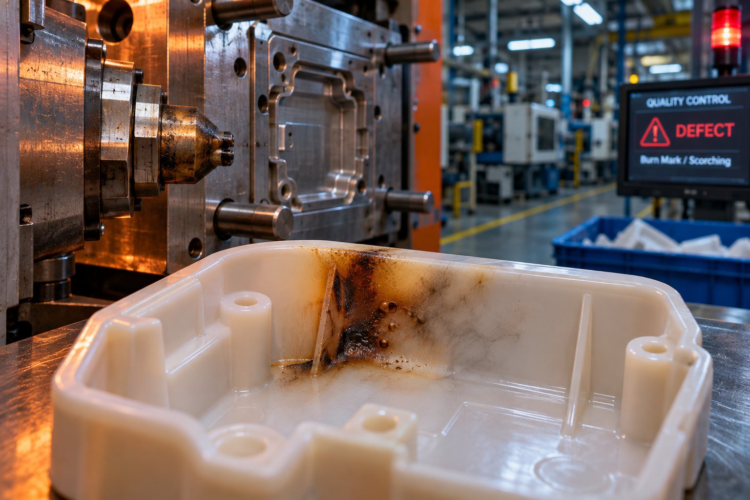
What Injection Molding Burn Marks Are and Why They Matter
Imagine pulling a freshly molded part from the tool only to find dark brown or black streaks scorched into the surface. That frustrating sight has a name, and it is one of the most persistent defects in plastic processing. Before you start adjusting parameters at random, though, you need to understand exactly what you are dealing with.
Injection molding burn marks are dark brown or black discolorations on molded parts caused by trapped gas igniting under extreme compression or by thermal degradation of the polymer melt. They typically appear near the end of the flow path, at rib and boss intersections, or along areas where air cannot escape the mold cavity during filling.
That definition covers the broad category, but it only scratches the surface. Most troubleshooting guides treat every burn mark the same way, leading technicians down a frustrating cycle of trial-and-error adjustments. A far more effective approach starts with classifying the defect by its root cause.
Defining Burn Marks and Their Three Root-Cause Categories
Not all burn marks in injection molding share the same origin. They fall into three distinct categories, and each one demands a different diagnostic path:
- Gas-trap burns occur when the advancing melt front seals off a pocket of air inside the cavity. Continued injection pressure compresses that trapped gas rapidly, raising its temperature high enough to auto-ignite the surrounding polymer. This is the well-known diesel effect. You will typically see dark brown or black char concentrated at the last-to-fill regions of the part, near ribs, bosses, or where multiple flow fronts converge.
- Material-degradation burns result from the polymer itself breaking down due to excessive heat exposure. Causes range from overly high barrel temperatures and aggressive screw speeds to prolonged residence time inside an oversized barrel. The visual signature differs: yellowish-brown streaks or a general discoloration distributed along the flow path rather than concentrated at dead-end pockets.
- Moisture-related burns appear when hygroscopic resins are not dried adequately before processing. Residual moisture flashes into steam at melt temperatures, creating splay-like defects that can include genuine brown discoloration from localized oxidation. These marks tend to cluster near the gate where the melt first enters the cavity.
Why does this classification matter on the production floor? Because a technician who treats a material-degradation burn like a gas-trap issue will waste hours adjusting injection speed and cleaning vents while the real culprit, an overheated barrel or worn screw, goes unaddressed. Identifying the burn-mark type first narrows the solution set immediately.
Why Burn Marks Signal More Than a Cosmetic Problem
It is tempting to dismiss a burn mark defect in injection molding as purely visual. The reality is far more consequential. At the molecular level, the discolored zone represents localized polymer chain scission. The material in that region has lost a portion of its original molecular weight, which directly reduces tensile strength, impact resistance, and fatigue life.
For medical device housings, automotive structural clips, or electrical connectors, that localized degradation can compromise the mechanical properties the part was designed to deliver. Regulatory frameworks governing these industries treat material degradation as a potential safety concern, not just an appearance issue. A study published in Polymers confirmed that burn marks affect both the appearance and mechanical properties of molded parts, reinforcing the need to treat this defect seriously.
From a business perspective, the cost implications escalate quickly. Scrap rates climb, secondary inspection steps get added, cycle times increase as operators slow injection speed in a reactive attempt to mask the symptom, and customer complaints erode confidence in the supplier. Burn marks in injection molding are, in every measurable way, a profitability problem disguised as a cosmetic one.
The key takeaway is straightforward: effective troubleshooting starts with accurate classification. The sections ahead build on this diagnostic-first framework, giving you the visual references, root-cause science, and corrective-action sequences needed to match each burn-mark type to its specific solution.
Visual Diagnosis Guide for Burn Mark Defects in Injection Molding
A burn mark on a molded part tells a story, but only if you know how to read it. Color, texture, and location each point toward a specific root cause. Rather than guessing, you can use visual clues to classify the defect within seconds and skip straight to the most productive corrective action. The diagnostic table below maps what you see on the part to what is most likely happening inside the mold or barrel.
Burn Mark Appearance-to-Cause Diagnostic Table
| Appearance (Color and Surface Texture) | Typical Location on Part | Most Likely Root-Cause Category | Recommended First Diagnostic Step |
|---|---|---|---|
| Dark brown to black char; rough, pitted, or cratered surface texture; edges may appear brittle or eroded | Last-to-fill regions: ends of flow paths, deep ribs, tall bosses, areas where multiple flow fronts converge | Gas-trap burn (diesel effect) | Run a short-shot study at reduced injection speed to confirm air-entrapment location; inspect vent condition at the parting line near the affected zone |
| Yellowish-brown streaks or overall amber-tinted discoloration; surface may appear smooth but off-color; sometimes accompanied by a chemical odor | Distributed along the flow path, often worsening from sprue to end of fill; may also appear in the sprue or runner system | Material-degradation burn (thermal or shear) | Measure actual melt temperature with a pyrometer (not barrel setpoint); calculate residence time and compare against resin supplier data sheet limits |
| Silver-streaked splay with occasional brown or tan tint; surface has a splashed or spray-like pattern; may feel slightly rough to the touch | Concentrated near the gate or in the first third of the flow path; pattern radiates outward from the gate area | Moisture-related burn (steam-induced oxidation) | Check dryer dew-point readings and verify actual granule moisture content with a moisture analyzer; inspect hopper lid seals and transfer lines for ambient air leaks |
When you encounter burn marks in plastic injection molding, start at this table. Match the visual evidence to a row, then follow the recommended diagnostic step before touching any machine parameter. That single habit eliminates the scattershot approach that wastes hours on the production floor.
Distinguishing Burn Marks from Splay, Silver Streaks, and Black Specks
Several other defects can look deceptively similar to a burn mark injection molding defect, and misidentifying them sends troubleshooting in the wrong direction entirely. Here is how to tell them apart:
- Splay (silver streaks without discoloration): Pure splay appears as bright, silvery streaks on the part surface, typically radiating from the gate. It lacks the brown or black tint that defines a genuine burn. Splay is most commonly driven by moisture, excessive melt temperature, or shear at the gate. If the streaks are purely silver with no color change, you are likely dealing with a volatile-release issue rather than combustion or polymer degradation. As injection molding practitioners have documented, splay marks can stem from hydrolysis, trapped air, gate design, or even pulsation irregularities in the screw, each requiring its own corrective path.
- Black specks: These are small, discrete dark particles scattered randomly across the part surface or embedded within the wall. Unlike a burn mark, they do not correlate with a specific location on every shot. Black specks typically originate from degraded material flushing out of hang-up zones inside the barrel, nozzle, or hot runner. A key test: if purging the barrel with a cleaning compound temporarily eliminates the specks, the source is almost certainly stagnant material inside the plasticizing unit rather than a gas-trap or process-temperature issue.
- General discoloration: A uniform yellow or amber shift across the entire part, with no localized streaks or char marks, usually points to a global processing issue such as barrel temperatures set too high across all zones, excessive residence time, or a contaminated material batch. Unlike the injection molding burn mark defect, this discoloration is even and consistent from shot to shot. It will not disappear by improving venting or slowing injection speed.
Three quick checks help you sort through the confusion every time:
- Location pattern: Does the defect appear in the same spot on every part? Consistent location strongly suggests gas-trap burns. Random scatter points toward black specks or contamination.
- Repeatability: Does the defect show up on every single shot, or does it come and go? Intermittent appearance is common with moisture-related issues and screw-related hang-up zones. Consistent, every-shot defects usually indicate a mold venting or process-temperature problem.
- Response to purging: Run several purge cycles with a high-viscosity cleaning compound. If the defect clears temporarily and then returns once production resin is back in the barrel, degraded material inside the machine is the most likely source. If purging has zero effect, the root cause lives in the mold side or in the process parameters.
Accurate visual classification is the fastest shortcut to a solution. Every minute spent identifying the correct defect type saves many more minutes of blind parameter adjustment. With the defect properly categorized, the next logical question becomes: what exactly happens inside the mold cavity when trapped gas reaches ignition temperatures, and which design features make it worse?
The Diesel Effect and Gas Trap Burns in Plastic Injection Molding
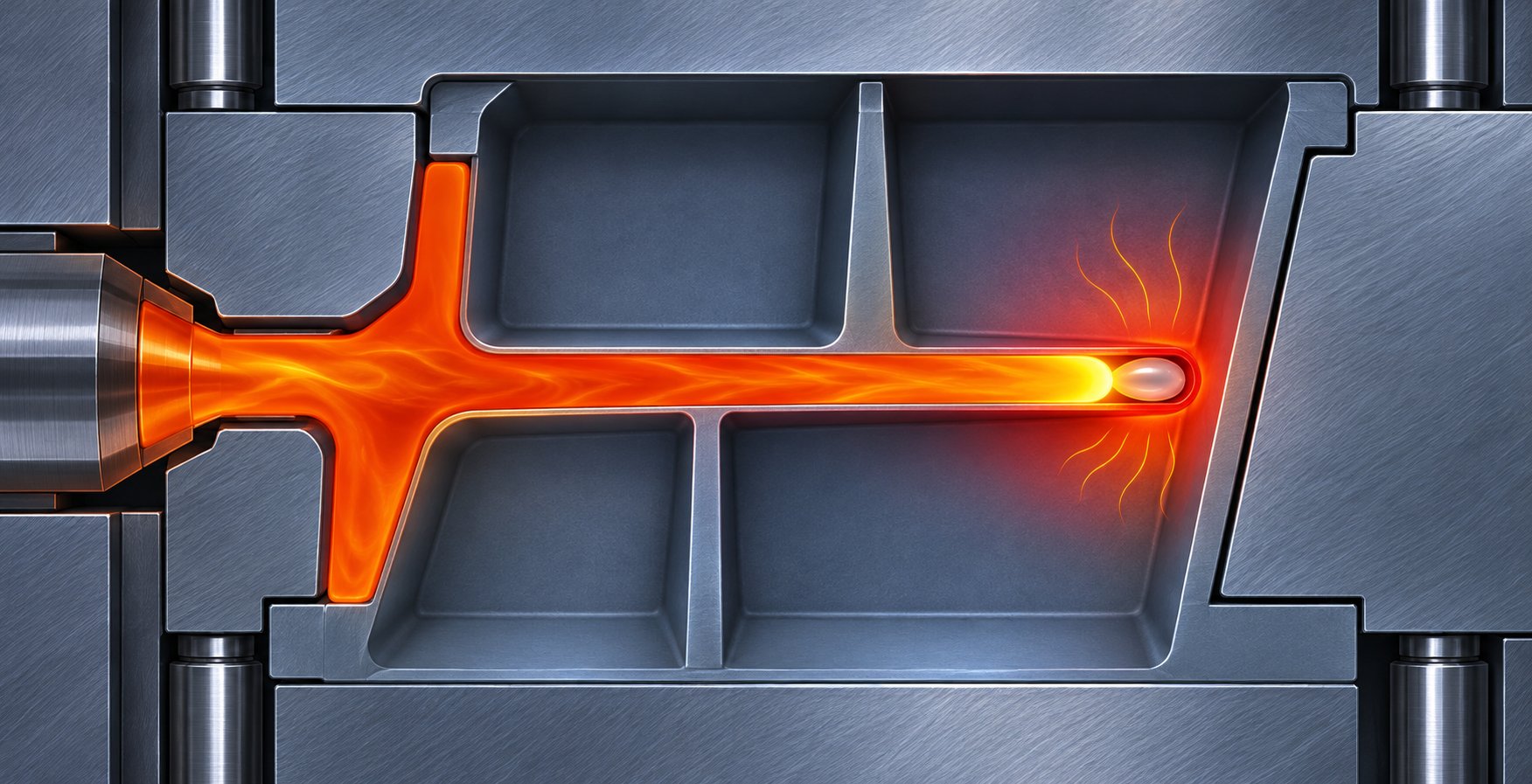
Picture a pocket of air sealed inside a mold cavity with nowhere to go. The melt front is advancing at high speed, and every millisecond the pressure climbs. That trapped gas does not simply sit there waiting. It compresses, heats, and eventually reaches temperatures violent enough to scorch the surrounding polymer. This is the diesel effect, and it is the single most common mechanism behind injection molding burn marks.
The Diesel Effect Explained Through Adiabatic Compression
The thermodynamic principle at work is identical to what fires a diesel engine. In a diesel cylinder, air is compressed so rapidly that it has no time to transfer heat to the surrounding metal walls. The result is adiabatic compression — a near-instantaneous temperature spike driven purely by pressure increase. When the fuel is injected into that superheated air, it ignites without a spark.
Inside a mold cavity, the sequence follows the same physics. As the melt front advances, it pushes air ahead of it toward vents on the parting line. Under normal conditions, that air escapes harmlessly. But when venting is inadequate, or when the fill rate is too fast for the gas to evacuate, the melt front seals off a pocket of air before it can exit. Continued injection pressure then compresses that sealed pocket almost instantaneously. Because the compression happens in milliseconds, the heat cannot dissipate into the surrounding steel. Local gas temperatures can spike to 300-600 degrees Celsius, hot enough to auto-ignite the polymer at the flow front. The charred residue left behind is the dark brown or black burn mark you find on the finished part.
Sounds extreme? Consider the scale: even a small air pocket compressed to a fraction of its original volume under thousands of psi of injection pressure generates enormous localized heat. The polymer at the leading edge of the melt has no escape. It scorches, carbonizes, and bonds to the part surface as a permanent defect. Understanding injection molding burn marks causes and solutions starts here, with this fundamental compression event, because every corrective action for gas-trap burns targets one of two things — giving the air a way out or slowing the compression rate.
How Mold Geometry, Gating, and Runner Design Create Gas Traps
The diesel effect does not happen randomly. Specific mold-design features create the conditions that trap air in predictable locations. Recognizing these features is what separates a reactive technician from a proactive tooling engineer.
Thin-wall transitions are a frequent culprit. When the flow path narrows suddenly, the melt accelerates through the thinner section. That burst of speed can outrun the air ahead of it, sealing off pockets before vents have time to evacuate the gas. The result is a plastic injection molding burn mark defect concentrated right at or just past the transition zone.
Deep ribs and tall bosses act as dead-end streets for air. As the melt fills the main wall and then diverts into a narrow, deep feature, air is pushed to the tip of the rib or boss with no exit path. Unless a vent or ejector-pin clearance exists at the end of that feature, the air compresses and ignites. This is why burn marks so frequently appear at rib tips and boss tops — they are geometric dead ends by design.
Converging flow fronts present a subtler trap. In parts with multiple flow paths, holes, or obstacles that split and rejoin the melt stream, air gets sandwiched between two approaching fronts. Neither front can push the air to a vent because the other front blocks the escape route. The trapped pocket compresses at the weld line and burns. As mold engineering specialists have noted, gas traps are common in parts with multiple gates, complex core geometry, or asymmetric fill patterns — and you can have vents everywhere on the parting line and still get burns simply because the trapped air has no connection to those vents at the moment of filling.
Gate type and location directly control where air ends up. An edge gate feeding a rectangular part pushes air toward the opposite wall in a relatively uniform pattern, making vent placement straightforward. A pin-point gate, by contrast, creates a radial flow front that can trap air in corners far from the parting line. A fan gate spreads the flow across a wide front, reducing the chance of localized air pockets but potentially trapping gas along the edges if the cavity geometry is not symmetric. Relocating the gate even a few millimeters can redirect the fill pattern enough to shift an air trap from an unventable location to a parting-line surface where it escapes easily.
Runner-system balance plays an equally critical role in multi-cavity molds. If runners are not balanced — meaning each cavity fills at a different rate — the fast-filling cavities pack out while the slow-filling cavities are still in the filling phase. Air in the last cavity to fill gets compressed by the packing pressure already building in the system. Unbalanced runners are a common root cause of plastic injection molding burn marks that appear in only one or two cavities of a multi-cavity tool while the others run clean.
Hot Runner Sequencing and Its Role in Air Entrapment
Hot-runner systems with valve gates add another layer of control — and another layer of risk. In a conventional cold-runner or open hot-tip system, all gates open simultaneously when injection begins. Valve-gate systems, however, allow each gate to open and close independently based on time, screw position, or cavity-pressure feedback.
When sequenced correctly, valve gates are a powerful tool against the injection molding burn marks defect. Sequential valve gating, for instance, opens a center gate first and delays the outer gates until the melt front has passed them. This creates a continuous, expanding flow front that pushes air ahead of it in a controlled wave toward the parting-line vents. As detailed in research on valve gate sequencing strategies, this approach minimizes knit lines and maintains a single, progressive fill pattern that avoids trapping air between converging fronts.
Poorly timed sequencing, however, can make things worse. Imagine a large panel mold with five valve gates, all opening simultaneously. Five separate flow fronts radiate outward and eventually collide, trapping air at every intersection. Alternatively, if a secondary gate opens too late — after the melt front has already passed it — the delayed flow creates a counter-current that pushes air back into a region the primary front already sealed off. The result is a gas pocket that no parting-line vent can reach.
The timing relationship between gate opening and fill progression is everything. Opening a downstream gate just before the primary melt front reaches it allows a smooth handoff with no air entrapment. Opening it too early creates competing fronts; opening it too late traps gas behind a sealed boundary. Cavity-pressure sensors placed near each gate can provide real-time feedback to trigger valve opening at exactly the right moment, turning a potential burn-mark source into a controlled, predictable fill sequence.
Every design decision covered here — wall thickness transitions, rib geometry, gate type, runner balance, and valve-gate timing — either creates or prevents the conditions for adiabatic compression. Yet even the best mold geometry cannot compensate if the gas-escape pathways themselves are compromised. That brings the focus to the mold's venting system, clamp-tonnage settings, and the maintenance practices that keep those critical escape routes functioning shot after shot.
Mold Venting, Clamp Tonnage, and Preventive Maintenance
Trapped gas needs a way out, and the mold's venting system is that exit route. You can optimize injection speed, adjust fill profiles, and fine-tune valve-gate timing all day long, but if the vents themselves are undersized, misplaced, or clogged with residue, compressed air still has nowhere to go. Effective injection mold venting for burn marks is not a secondary consideration — it is the frontline defense against the diesel effect described in the previous section.
Vent Design Principles for Gas Escape
A vent is deceptively simple in concept: a shallow channel machined into the parting line that allows air to pass but prevents molten plastic from escaping. In practice, three interdependent dimensions determine whether that channel actually works.
Vent depth is the most critical parameter. It defines the gap between the two mold halves at the vent location. Too shallow, and gas cannot evacuate fast enough to keep up with the advancing melt front. Too deep, and molten resin bleeds through, creating flash. The ideal depth depends directly on the resin's viscosity at processing temperature. Industry-standard recommendations range from 0.02 to 0.05 mm for high-viscosity materials like HDPE and TPE, down to just 0.01 to 0.02 mm for low-viscosity engineering resins like polycarbonate and nylon. Getting this number wrong by even a few thousandths of a millimeter shifts the balance from clean gas evacuation to either trapped air or flash.
Vent land length — the distance from the cavity edge to the point where the relief channel begins — controls how much resistance the gas encounters in the sealing zone. A typical range of 0.51 to 1.52 mm works well for most applications. Shorter lands evacuate gas faster but increase the risk of resin leaking through. Longer lands offer a safer seal but can throttle gas flow enough to allow compression buildup at high fill rates.
Total vent area is the sum of all individual vent cross-sections around the cavity perimeter, and it must be evaluated relative to the projected part area and fill rate. A single vent rarely provides enough capacity. Multiple vents distributed at every location where air is likely to collect — end-of-fill zones, rib tips, boss ends, and weld-line intersections — ensure that gas has more than one escape route. For complex geometries where parting-line vents cannot reach, specialized solutions such as ejector-pin venting (using the functional clearance of 0.002 to 0.005 mm per side around each pin) or porous sintered-steel inserts with controlled porosity of 7 to 30 microns provide gas pathways into otherwise sealed regions.
Clamp Tonnage, Parting Line Seal, and Their Effect on Venting
Here is a scenario many molders have experienced: burn marks appear on a tool that ran perfectly last week. Nothing in the process changed — same resin, same temperatures, same speeds. The only adjustment? Someone bumped up the clamp tonnage to address a flash complaint on a different area of the part.
Excess clamp tonnage is a silent burn-mark trigger that injection molding burn marks mold design discussions rarely address. The parting line is not just a sealing surface for plastic — it is also the primary gas-escape pathway for the entire cavity. Every vent machined into the parting line relies on a controlled gap to function. When clamp force exceeds what the tool actually needs, the parting-line surfaces compress beyond their designed clearance. Vents that were machined to 0.02 mm deep can be crushed to near-zero effective depth under excessive tonnage, blocking gas evacuation across the entire perimeter.
The result is predictable: air that previously escaped cleanly now compresses and ignites. Burns appear at parting-line intersections, near ribs that vent through the parting surface, or in any region that depends on the parting-line gap for gas release. Technicians who are unaware of the tonnage change may spend hours adjusting injection speed and melt temperature while the real fix is simply dialing the clamp back to the correct setting.
Parting-line flatness compounds the issue. A mold with uneven parting surfaces — whether from wear, damage, or poor original machining — creates zones of tight seal and zones of slight gap. Gas preferentially escapes through the looser zones, leaving the tight zones with no evacuation path. Over time, as the mold cycles and the parting surface wears unevenly, the effective venting pattern shifts. Regions that vented adequately at tool launch gradually lose their gas-escape capacity, and burn marks creep in progressively over thousands of cycles.
Preventive Vent Maintenance Schedules and Mold Coatings
Vents do not stay clean forever. Every shot cycle deposits trace amounts of volatile residue — plasticizers, mold-release agents, stabilizer byproducts, and low-molecular-weight polymer fragments — onto the vent channel walls. Over hundreds or thousands of shots, that residue accumulates and narrows the effective cross-section until the vent is partially or fully blocked. As mold engineering resources document, progressive vent accumulation reduces the effective vent cross-section until it is completely blocked, turning a clean-running tool into a burn-mark generator.
A structured preventive maintenance framework keeps vents functional before problems appear on parts:
- Visual inspection every production run or every 5,000-10,000 cycles (whichever comes first). Look for discoloration, residue buildup, or shiny compression marks on the vent land that indicate the channel is being crushed shut under clamp force.
- Watch for flash formation at vent locations. Counterintuitively, flash at a vent is a useful diagnostic signal — it confirms gas was escaping through that channel. If flash suddenly stops appearing at a vent that previously showed it, the channel may be clogged rather than improved.
- Track progressive burn-mark worsening over production runs. If burns start faint and gradually darken or spread across cycles without any process change, vent fouling is the most likely explanation. This gradual pattern distinguishes vent-maintenance burns from sudden onset issues caused by parameter errors.
- Clean vents using ultrasonic cleaning, brass brushes, or dedicated mold cleaners during scheduled maintenance intervals. Avoid steel tools that can widen the vent channel and create a flash path. For high-volume production molds, clean parting-line vents every preventive maintenance cycle — typically every 50,000 to 100,000 shots, adjusted based on resin off-gassing behavior.
- Apply mold coatings and surface treatments to reduce vent clogging. Nickel-PTFE coatings, DLC (diamond-like carbon) coatings, and specialized anti-stick surface treatments lower the adhesion of off-gassing residues to vent channel walls. These coatings extend the interval between required cleanings and are particularly valuable for resins that produce heavy off-gassing, such as PVC, flame-retardant grades, and glass-filled nylons.
The most powerful strategy for how to prevent burn marks in injection molding, however, starts long before the mold ever reaches a press. Mold-flow simulation software can predict air-trap locations during the DFM phase by modeling how the melt front progresses through the cavity, where flow fronts converge, and where gas will collect at end-of-fill regions. These predictions allow tooling engineers to specify vent locations, depths, and supplementary venting features — ejector-pin vents, porous inserts, or even vacuum-assisted venting — before any steel is cut. Simulation does not automatically produce a finished vent design, but it provides a risk map that dramatically reduces the likelihood of discovering gas-trap burns during first-article trials.
Shifting burn-mark prevention upstream to the design phase instead of treating it solely as a production-floor reaction is the difference between a mold that runs cleanly from day one and a mold that requires weeks of trial-and-error parameter chasing. Vent design, clamp-tonnage discipline, and scheduled maintenance form the mold-side foundation of defect prevention — but they address only half the equation. The other half lives inside the barrel, where screw speed, back pressure, and residence time can degrade the polymer before it ever reaches the cavity.
Machine Parameters That Drive Material Degradation Burns
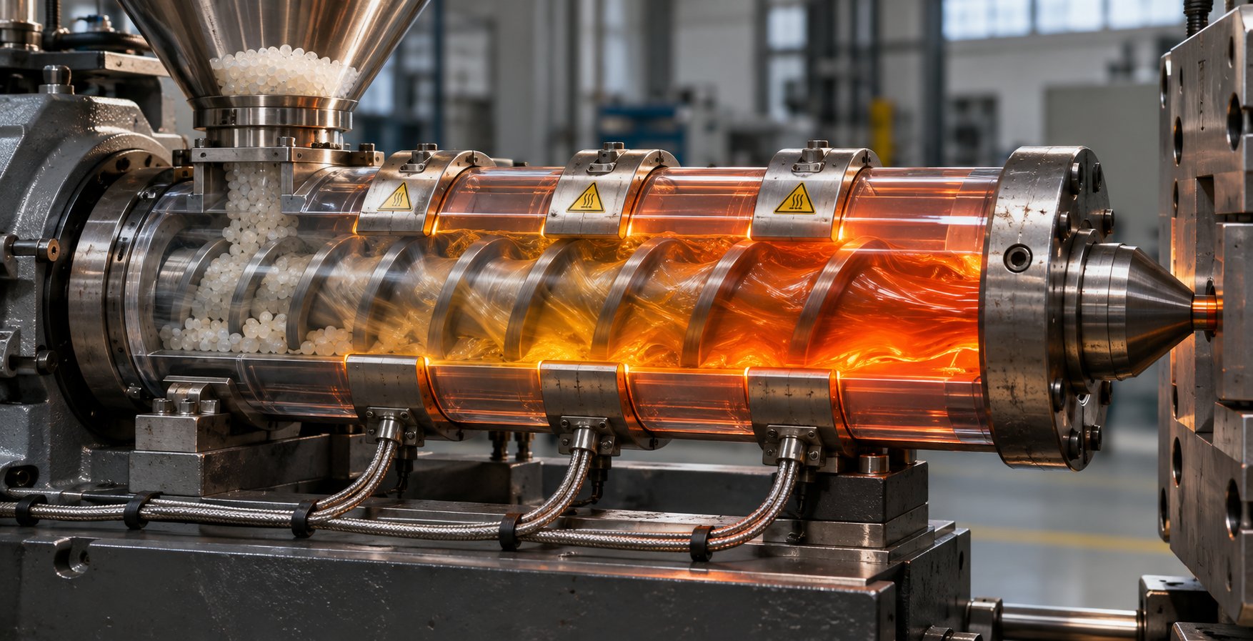
Gas-trap burns get the most attention because they are dramatic and localized. Material-degradation burns, by contrast, are subtler and far more insidious. They do not announce themselves with a charred spot at the end of fill. Instead, they creep in as yellowish-brown streaks, slight amber shifts, or an off-smell that hints something is chemically wrong with the melt. The root cause is not trapped air — it is what happens to the polymer inside the barrel before it ever reaches the cavity. Injection molding machine settings burn marks of this type are driven by three interconnected variables: screw speed, back pressure, and residence time.
Screw Speed, Back Pressure, and Shear-Induced Degradation
Every polymer has a processing window — a range of temperatures and shear rates within which it flows, fills, and solidifies without molecular damage. Push beyond that window, and the long polymer chains begin to break apart. This chain scission releases volatile gases, discolors the melt, and weakens the finished part. The machine's plasticizing unit is where the risk starts.
Screw speed is the primary driver of shear heat. As the screw rotates during recovery, it drags resin pellets through a progressively narrowing channel between the screw flights and the barrel wall. Friction between the pellets, the screw, and the barrel generates heat — not from the heater bands, but from mechanical energy converted into thermal energy at the molecular level. The faster the screw turns, the higher the shear rate, and the more heat is generated internally within the melt. You might set your barrel temperature profile perfectly within the resin supplier's recommended range and still push actual melt temperature 15-30 degrees Celsius above the setpoint simply by running the screw too fast. That overshoot can land the resin squarely in its degradation zone. Injection molding burn marks caused by excessive screw speed often appear as faint discoloration distributed along the entire flow path rather than concentrated at one spot, because the polymer is already partially degraded before injection begins.
Back pressure compounds the effect. During screw recovery, back pressure is the hydraulic resistance applied against the screw's rearward movement as it meters new material. Moderate back pressure is beneficial — it improves melt homogeneity, eliminates air trapped between pellets, and produces a more consistent shot weight. However, raising it too high forces the screw to work harder to push material forward, which increases shear energy input and raises melt temperature further. Elevated back pressure also slows screw recovery, meaning the material spends more time being actively worked in the heated barrel. The combined result is both a hotter melt and a longer heat exposure — a double penalty that accelerates degradation. Back pressure burn marks in injection molding are especially common when processors crank up the setting to improve color dispersion or additive mixing without accounting for the thermal cost.
Residence Time and Barrel Sizing Considerations
Imagine leaving a steak on a hot grill. Even at the correct temperature, if it sits there long enough, it burns. Polymer behaves the same way. Residence time is the total duration that plastic is exposed to heat inside the barrel, from the moment a pellet enters the feed throat to the moment it exits the nozzle as part of a shot. Every resin has a maximum residence time it can tolerate at a given temperature before meaningful degradation begins.
Two common production-floor scenarios push residence time beyond safe limits:
- Oversized barrels: When a mold that requires a small shot is run on a machine with a large barrel, each injection cycle uses only a small fraction of the barrel's capacity. The remaining material sits at melt temperature, cycling through recovery after recovery, slowly degrading. As injection molding process specialists note, small shot sizes that use minimal barrel capacity result in long residence times and polymer degradation, while large shot sizes exceeding 50% of barrel capacity lead to poor melt uniformity. The recommended sweet spot is a shot size that uses 25% to 65% of barrel capacity.
- Slow cycle times: Extended cooling times, long mold-open delays for part removal, or frequent production interruptions all increase the time material spends sitting hot in the barrel. A mold running a 60-second cycle on a barrel designed for 30-second cycles effectively doubles the heat exposure for every pellet passing through the system.
Residence time material degradation in injection molding is particularly deceptive because it does not trigger an alarm. The barrel temperature readout looks normal. The screw speed and back pressure may be within spec. Yet the polymer is quietly undergoing chain scission, generating low-molecular-weight fragments and volatile gases that discolor the melt and compromise part properties. These volatiles can also create gas bubbles that mimic other defects, further complicating diagnosis.
The table below consolidates these machine-side parameters into a quick diagnostic reference:
| Parameter | How It Contributes to Degradation | Diagnostic Check |
|---|---|---|
| Screw Speed (RPM) | Higher RPM increases shear rate in the screw channel, generating internal frictional heat that raises actual melt temperature above barrel setpoints. Excessive shear physically breaks polymer chains. | Measure actual melt temperature with an air-shot pyrometer reading and compare to barrel zone setpoints. A difference greater than 10-15 degrees Celsius suggests excessive shear heating. Reduce RPM and recheck. |
| Back Pressure | Adds shear energy during recovery and extends screw recovery time, increasing both melt temperature and heat exposure duration. Amplifies the thermal effect of high screw speed. | Monitor screw recovery time. If recovery completes well before the cooling timer expires, back pressure may be higher than necessary. Reduce incrementally while monitoring shot-weight consistency. |
| Barrel Temperature Profile | Zone temperatures set above the resin's recommended range push the polymer closer to its degradation threshold. A flat or reverse profile (rear zones hotter than front) can overheat material early in the barrel. | Verify all zone setpoints against the resin manufacturer's processing data sheet. Check for stuck or overshooting heater bands using zone-by-zone actual vs. setpoint comparison. Confirm a proper rear-to-front ascending profile for most resins. |
| Cycle Time | Longer cycles increase total residence time. Material in the barrel absorbs heat through additional recovery strokes and idle dwell, pushing cumulative exposure beyond the resin's safe threshold. | Calculate residence time: (barrel capacity / shot size) x cycle time. Compare the result to the resin supplier's maximum recommended residence time. If the ratio exceeds 5-6 shots of inventory, consider a smaller barrel or faster cycle. |
Processing Window Guidance by Resin Category
Not all plastics respond to these parameters the same way. A screw speed and back pressure combination that runs polyethylene without any issue can devastate polycarbonate. The differences come down to two characteristics: shear sensitivity and thermal stability.
Amorphous resins — polycarbonate (PC), ABS, PMMA, polysulfone — tend to be more shear-sensitive. Their disordered molecular structure means the chains entangle readily, and high shear rates generate proportionally more frictional heat. Polycarbonate, for example, has a relatively narrow processing window. Pushing screw speed beyond moderate levels can spike actual melt temperature 20-30 degrees Celsius above setpoint, driving the resin into a degradation range where it yellows and loses impact strength. ABS, while more forgiving, still produces noticeable discoloration when shear heat is excessive.
Semi-crystalline resins — nylon (PA), PBT, POM, PET — present a different risk profile. Their crystalline structure means they have sharper melt points and generally tolerate higher shear rates during plasticizing without as much frictional heat buildup. However, many semi-crystalline engineering resins have narrower thermal-stability windows once molten. Nylon 6 and nylon 66, for instance, oxidize rapidly at elevated temperatures, particularly in the presence of moisture. POM (acetal) is notoriously sensitive: even modest overheating can trigger depolymerization that releases formaldehyde gas, creating burn marks and a sharp chemical odor.
Commodity resins — polyethylene (PE), polypropylene (PP), and general-purpose polystyrene (GPPS) — are the most forgiving group. They tolerate wider ranges of screw speed and back pressure without immediate degradation. Their residence-time thresholds are also more generous, often tolerating 8-10 minutes at melt temperature before significant molecular-weight loss occurs. This is in stark contrast to engineering resins like PC or POM, where residence times beyond 5-6 minutes can produce visible discoloration and measurable property loss.
The practical takeaway? When injection molding burn marks screw speed adjustments alone do not resolve the discoloration, check whether the barrel, back pressure, and cycle time are collectively pushing the resin beyond its category-specific tolerance. A commodity resin may forgive sloppy parameter management. An engineering resin will not. And when degradation burns persist even after process optimization, the question shifts from what the machine is doing to what condition the machine is in — because worn screws and barrels create degradation pathways that no parameter adjustment can compensate for.
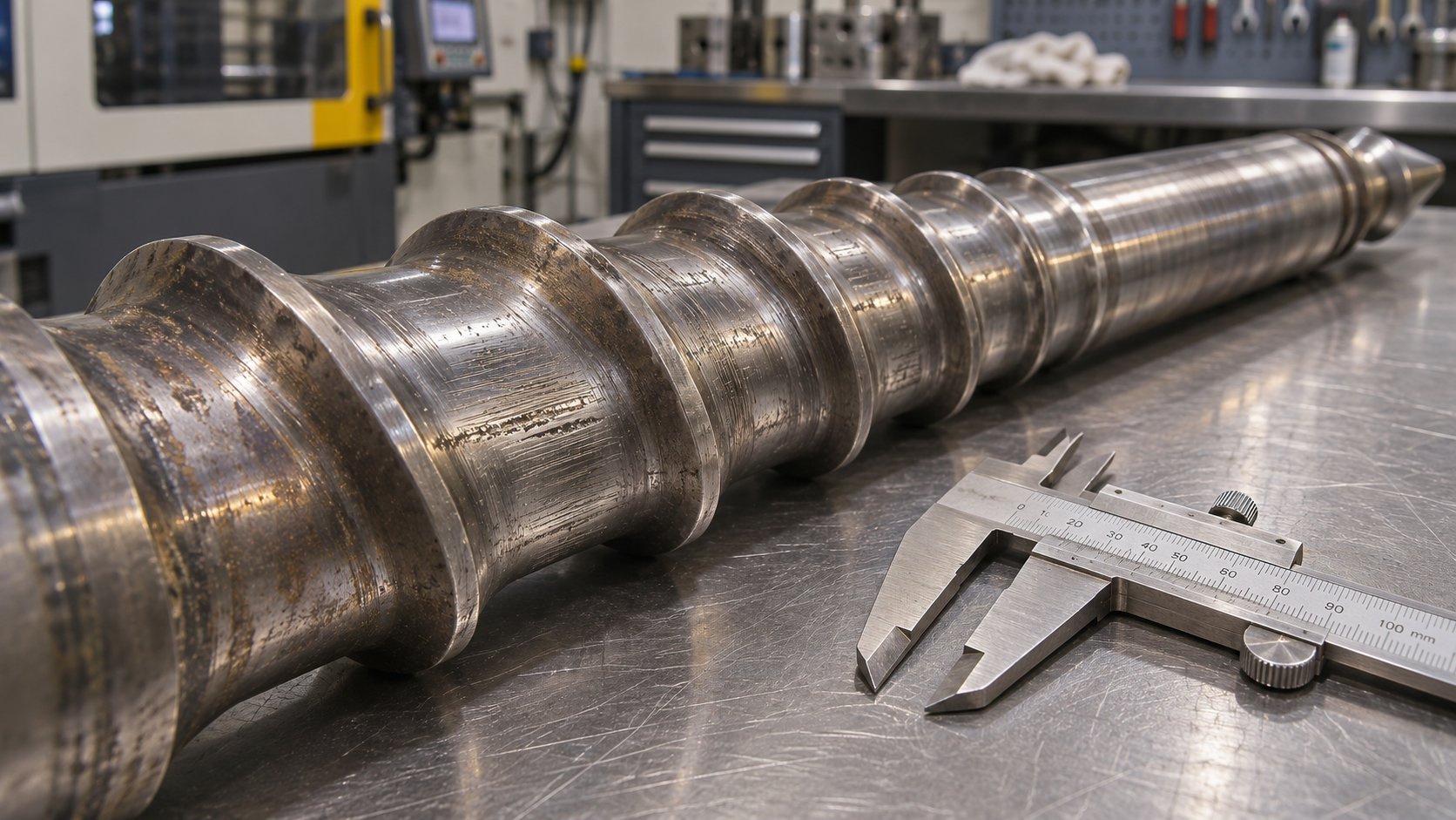
Screw and Barrel Wear as a Progressive Burn Mark Source
A technician who has methodically dialed in barrel temperatures, trimmed screw speed, verified back pressure, and confirmed residence time within spec still finds yellowish-brown streaks and dark particles appearing on molded parts. Every parameter looks right on the controller screen. Yet the defect persists — and slowly, almost imperceptibly, it gets worse week after week. This is the hallmark of a hardware-driven degradation problem, and it is one of the most underdiagnosed causes of injection molding burn marks in production environments.
The reason it goes undetected for so long is simple: screw and barrel wear is gradual. It does not trigger an alarm or throw a fault code. Instead, it quietly creates internal dead zones where resin stagnates, overheats, and degrades into darkened particles that periodically flush into the melt stream. By the time the defect is visible on parts, the wear has often been progressing for months.
How Screw and Barrel Wear Creates Material Hang-Up Zones
Inside a healthy plasticizing unit, resin moves in a continuous, controlled flow from the feed throat to the nozzle. The screw flights push material forward with minimal stagnation, and the tight clearance between the flight outer diameter and the barrel inner wall ensures efficient pressure development with limited backflow. When that clearance opens up due to wear, the entire flow dynamic changes.
Three distinct wear mechanisms create progressively worsening dead zones, each tied to the materials being processed:
Adhesive wear on flight lands occurs when the screw flight OD and the barrel wall experience metal-to-metal contact under high pressure. As plastics processing engineers have documented, the majority of wear concentrates in the transition section and the last few turns of the metering zone — areas that experience the highest pressures and temperatures. Over time, the flight OD wears down, widening the radial clearance. Resin leaks backward over the worn flights instead of being pushed forward efficiently. This leakage flow forces the material through excessive shear, raising its temperature and creating a thin film of overheated polymer clinging to the barrel wall in the worn zone. That film does not get flushed out on every shot. It sits, cooks, and eventually carbonizes into dark particles that break loose unpredictably.
Abrasive wear from filled resins accelerates the problem dramatically. Glass fibers, calcium carbonate, talc, and mineral fillers act like sandpaper on both the screw and barrel surfaces. The severity depends on filler concentration and particle geometry — larger particles with sharper corners wear faster than smaller, rounder ones. Abrasive wear does not just erode the flight OD. It gouges the screw root as well, particularly on the forwarding side of the flights where solids pressure is highest. These gouges and pits become permanent hang-up zones where resin lodges, degrades, and periodically releases darkened fragments into the flow. In extreme cases, root wear undermines the substrate beneath hardface inlays, causing the brittle coating to chip away and leaving rough, irregular surfaces that trap even more material.
Corrosive wear from chemically aggressive resins — PVC, flame-retardant compounds, and certain fluoropolymers — attacks the metal surfaces chemically rather than mechanically. PVC, for example, releases hydrochloric acid when it degrades at elevated temperatures. That acid etches microscopic pits into the barrel wall and screw surface, creating a rough, porous texture that traps thin layers of resin. Each trapped layer degrades, releases more corrosive byproducts, and accelerates the pitting cycle. The result is a progressively rougher internal surface covered in micro-dead-zones, each one a potential source of screw barrel wear injection molding burn marks that no amount of parameter tweaking will resolve.
Mixing sections and barrier flights suffer their own version of this degradation. Their undercut geometries are designed to shear resin for better dispersion and melting. As these features wear, they lose their ability to actively process the melt — but they retain their ability to trap material in the widened gaps. Industry research confirms that worn mixing sections lose adequate dispersion capacity, and worn barrier flights lose melting efficiency. Both conditions extend the time resin spends in a partially processed, vulnerable state inside the barrel.
Warning Signs That Point to Hardware-Related Degradation
The most frustrating aspect of wear-driven burn marks is their slow onset. A technician troubleshooting injection molding black specks and burn marks will typically start by adjusting process parameters — lowering barrel temperatures, reducing screw speed, cleaning vents. Those adjustments may produce a temporary improvement because they reduce the overall thermal load on the already-degrading material. But the root cause — the physical condition of the screw and barrel — has not changed. Within days or weeks, the defect returns, often slightly worse than before.
Recognizing the pattern early saves significant production losses. Watch for these warning signs that point specifically to hardware deterioration rather than process drift:
- Burn marks that do not respond to process parameter adjustments. You have lowered melt temperature, reduced screw speed, cut back pressure, and verified residence time — yet discoloration or dark streaks persist. When every process lever has been pulled without improvement, the problem is almost certainly mechanical.
- Increasing frequency of black specks over production runs. Degraded polymer and carbon buildup inside the screw and barrel periodically break loose and enter the melt stream. Early on, specks may appear once every few hundred shots. As wear worsens and hang-up zones multiply, the frequency climbs — a few specks per run become dozens per hour. Purging provides temporary relief, but the specks return faster each time because the rough, worn surfaces regenerate deposits quickly.
- Rising melt temperature readings without profile changes. As radial clearance between the screw flights and barrel wall increases, resin leaks backward over the worn flights and gets sheared repeatedly. This generates additional frictional heat that shows up as a higher actual melt temperature even though barrel zone setpoints have not changed. As processing experts have noted, operators typically see a rise in melt temperature and increased energy consumption as wear progresses, forcing higher RPM to maintain throughput — which only compounds the thermal problem.
- Screw recovery time drift. A worn screw loses pumping efficiency. The operator may notice that recovery time gradually lengthens over weeks or months, or that recovery time becomes inconsistent from shot to shot. Both patterns indicate that the screw is no longer developing adequate pressure to meter material reliably, and that resin is spending unpredictable amounts of time in the heated barrel.
- Shot-weight inconsistency that worsens over time. A degraded check ring — the valve at the front of the screw that prevents backflow during injection — is a particularly insidious contributor. Worn check valves allow melt to leak backward during the injection and packing phases. That backward leakage means some material gets pushed back into the barrel, re-heated, and re-injected on the next cycle. Each backflow event adds an extra residence-time loop for a portion of the melt, raising its cumulative heat exposure well beyond the resin's tolerance threshold. The resulting check ring wear degradation in injection molding shows up as sporadic discolored streaks or particles — not on every shot, but often enough to spike reject rates.
The gradual nature of all these symptoms is what makes hardware-related burns so easy to misattribute. Technicians understandably reach for the parameters they control directly. When those adjustments produce marginal or temporary improvement, the issue gets logged as "process sensitivity" or "resin lot variation" rather than the mechanical root cause it actually is.
Evaluating Screw and Barrel Replacement to Eliminate Progressive Burns
When diagnosis confirms that wear is the driving factor, the corrective path leads to hardware evaluation. Pulling the screw for inspection is the definitive diagnostic step. Measurable indicators include flight OD diameter loss compared to original specifications, visible root wear or pitting, check-ring seat damage, and barrel ID measurements taken at multiple points along its length. A common industry guideline considers flight clearance at four times the original tolerance as the threshold for replacement, though resin viscosity matters significantly — lower-viscosity resins like polypropylene suffer greater output and quality loss at the same clearance than higher-viscosity materials like polyethylene.
Replacement decisions are not just about matching the original part number. The screw geometry, metallurgy, and surface treatment should be matched to the specific resin, filler package, and shot-size requirements of the application. A general-purpose screw that came with the machine at purchase may never have been ideal for the resin currently running. Injection molding screw barrel replacement burn marks can sometimes be eliminated not just by restoring original clearances but by upgrading to a design better suited to the application.
This is where working with a specialized supplier adds practical value. NANHAIYA's custom injection molding screw barrels are built around the specific machine specifications, resin characteristics, and shot-size requirements of each application. Their technical review evaluates screw geometry, existing wear patterns, melting and mixing performance, and material-retention concerns to match the replacement screw and barrel to the molder's actual production conditions — not just the machine's nameplate data. For operations where progressive degradation burns have been traced to hardware condition, this kind of application-specific evaluation helps ensure the replacement addresses the root cause rather than simply restoring the original (and potentially inadequate) configuration.
Whether you rebuild or replace, the key insight is the same: screw and barrel wear is not a maintenance nuisance to tolerate — it is an active, worsening source of material degradation that produces burn marks, black specks, and property loss no process adjustment can overcome. Addressing it restores the baseline mechanical condition the plasticizing unit needs to keep resin within its safe processing window. Yet even a perfectly maintained barrel cannot protect a resin that arrives at the feed throat carrying excess moisture or one that has an inherently narrow thermal-stability window. Those material-specific vulnerabilities introduce an entirely separate class of burn-like defects that demand their own diagnostic approach.
Moisture-Related Burns and Material-Specific Susceptibility
A barrel in perfect mechanical condition, running optimized parameters on a well-vented mold, can still produce parts with brown-tinted streaks and surface defects that look remarkably like burn marks. The culprit is not trapped air, worn hardware, or excessive shear. It is water — sometimes just a few hundredths of a percent too much — hiding inside the resin pellets themselves. Moisture burn marks in injection molding represent a distinct defect category that demands its own diagnostic logic, and certain resin families are far more vulnerable than others.
Moisture as a Hidden Contributor to Burn-Like Defects
Hygroscopic resins absorb moisture from ambient air. Nylon (PA), polycarbonate (PC), PET, and ABS all pull water molecules into their polymer structure during storage and handling. When these resins enter the barrel without adequate drying, the absorbed water does not simply evaporate harmlessly. At melt temperatures — typically 230 to 320 degrees Celsius depending on the resin — that moisture flashes into superheated steam almost instantaneously. The expanding steam disrupts the melt front, creating the characteristic silvery splay streaks that radiate outward from the gate.
Here is where the confusion starts. Pure moisture splay appears as bright, silver-white streaks with no color change. But when steam generation is severe enough, it does more than just disrupt the flow surface. The superheated steam creates localized pockets of water vapor trapped within the melt. At processing temperatures, that water vapor reacts with the polymer chains in an oxidation or hydrolysis reaction, producing genuine brown or tan discoloration layered on top of the splay pattern. The result is a defect that visually mimics a true burn mark — brownish streaks near the gate area — even though the root cause is moisture rather than gas compression or thermal degradation.
A degradation study conducted at the American Injection Molding Institute demonstrated just how severe this effect can be. Polycarbonate processed with excess moisture at elevated melt temperatures showed a 614% increase in melt flow rate — a catastrophic indicator of molecular weight loss. PET was even less forgiving: even at low melt temperatures and short residence times, wet PET experienced a 529% increase in melt flow rate. These are not cosmetic problems. They represent fundamental structural compromise driven entirely by inadequate drying.
For hydrolyzable resins like PA, PBT, and TPU, the water actually attacks the backbone of the polymer chain, breaking it into shorter segments and dramatically reducing mechanical properties. For hydrophilic resins like ABS and POM, moisture primarily causes surface-level cosmetic defects because the water reacts with pendant groups rather than the chain backbone. Both mechanisms, however, can produce discoloration that gets misdiagnosed as a thermal or gas-trap burn if the technician does not check moisture content first.
Telling Moisture Burns Apart from Gas-Trap Burns
How do you know whether the brown streaks on your parts are coming from trapped air compressing inside the cavity or from steam erupting out of wet resin? Two diagnostic clues make the distinction clear:
- Location relative to the gate. Hygroscopic resin burn marks in injection molding cluster near the gate or within the first third of the flow path. This is because the moisture flashes into steam as soon as the resin hits the high-shear, high-temperature zone at the gate orifice. The defect radiates outward from the gate in a fan or splash pattern. Gas-trap burns, by contrast, concentrate at the last-to-fill regions — end of flow paths, rib tips, boss tops, and weld-line intersections. If the discoloration is worst right at the gate and fades as you move toward the end of fill, moisture is your primary suspect.
- Response to purging. Run several purge shots with properly dried material. If the brown-tinted splay disappears quickly once dry resin reaches the barrel and returns when the suspect material is reintroduced, moisture is confirmed. Gas-trap burns, on the other hand, will persist regardless of material condition because their cause is geometric — trapped air in the mold cavity does not care whether the resin is wet or dry.
A quick moisture-content test with a halogen or Karl Fischer analyzer provides definitive confirmation. Most hygroscopic engineering resins require moisture levels below 0.02% for safe processing. Anything above that threshold places the resin squarely in the danger zone for hydrolysis-driven degradation and the discolored splay that follows.
Heat-Sensitive Resins That Demand Narrower Processing Windows
Moisture is not the only material-side vulnerability. Some resin families carry inherently low degradation thresholds that make them prone to burn-like defects even when perfectly dried. Processing these materials requires tighter control over every thermal variable — and a smaller margin for error than commodity plastics allow.
PVC is the textbook example. When polyvinyl chloride overheats — even by a modest margin above its recommended processing range — it undergoes dehydrochlorination, releasing hydrochloric acid gas. That acid is corrosive to both the mold and barrel surfaces, and the chemical reaction produces visible brown-to-black discoloration in the part. PVC degradation burn marks in injection molding are especially dangerous because the released HCl accelerates further degradation in a self-reinforcing cycle: the acid catalyzes more chain scission, which releases more acid, which degrades the material faster.
POM (acetal) presents a different but equally serious risk. Overheating triggers depolymerization — the polymer literally unzips back into formaldehyde monomer. You will notice a sharp, pungent chemical odor at the press before you even see the discoloration on parts. Formaldehyde gas buildup inside the cavity can itself combust in a localized diesel-effect event, producing char marks that look identical to air-trap burns but originate from chemical decomposition rather than mechanical gas compression.
Flame-retardant grades across multiple resin families off-gas aggressively during processing. The flame-retardant additives — particularly halogenated and phosphorus-based compounds — begin to decompose at temperatures only slightly above the base resin's normal processing range. The volatile byproducts these additives release are chemically reactive, corrosive to tooling, and produce heavy deposits on vent surfaces. Heat sensitive resin injection molding burn marks from FR grades often show a progressive pattern: parts run clean for the first few hundred shots, then burns worsen steadily as vent channels clog with off-gassing residue.
Certain nylons — particularly PA6 and PA66 — oxidize rapidly at elevated temperatures when exposed to oxygen. Even brief residence in a partially empty barrel where air contacts the melt surface can produce yellowed or browned material that contaminates subsequent shots. Nylons also have a well-documented sensitivity to drying temperature: as material scientists have noted, drying temperature has a much greater impact on nylon oxidation than drying time. Setting the dryer 10 to 15 degrees Celsius above the recommended range to speed up drying can actually degrade the resin before it even reaches the barrel.
Resin-Family Processing Guidance to Minimize Burn Risk
The table below consolidates the key degradation risks, critical processing concerns, and burn prevention priorities for the resin families most commonly associated with discoloration defects. Use it as a quick reference when diagnosing material-specific burn-like issues on the production floor.
| Resin Family | Key Degradation Risk | Critical Processing Concern | Burn Prevention Priority |
|---|---|---|---|
| Nylon (PA6, PA66) | Hydrolysis from moisture; oxidation at elevated temperatures | Must dry to below 0.02% moisture; drying temperature must not exceed supplier recommendation; oxidizes rapidly in partially empty barrels | Verify dryer dew point and drying temperature; minimize barrel air exposure; keep residence time short |
| Polycarbonate (PC) | Hydrolysis from moisture; shear-sensitive with narrow thermal window | Requires drying to below 0.02%; melt temperature spikes from excessive screw speed cause yellowing and molecular weight loss | Confirm moisture content before every run; moderate screw RPM; monitor actual vs. set melt temperature |
| PET | Extreme hydrolysis sensitivity; degrades catastrophically when wet | Even trace moisture at low melt temperature causes severe molecular weight loss; very tight drying requirement below 0.005% | Use desiccant dryers with verified dew point below -30 degrees Celsius; never interrupt drying cycle; run short residence times |
| ABS | Moisture causes cosmetic splay; prolonged heat causes butadiene phase degradation | Dry to below 0.05%; butadiene rubber component yellows and embrittles at excessive melt temperatures or long residence times | Dry adequately but prioritize residence time control; avoid barrel temperatures at the upper end of the processing range |
| PVC | Dehydrochlorination releasing HCl gas; self-accelerating degradation cycle | Very narrow processing window; shear sensitivity requires low screw speeds; HCl corrodes barrel and mold surfaces | Use corrosion-resistant screw and barrel metallurgy; minimize residence time; never exceed recommended melt temperature; clean vents frequently |
| POM (Acetal) | Depolymerization releasing formaldehyde gas; gas can combust in cavity | Cannot tolerate extended residence time; degrades rapidly above a narrow thermal ceiling; formaldehyde release creates safety and odor concerns | Match barrel size to shot size to minimize residence time; maintain strict temperature control; ensure excellent mold venting to evacuate formaldehyde gas |
| Flame-Retardant Grades | Additive decomposition releasing corrosive, reactive volatiles; heavy off-gassing clogs vents | Narrow additive-stability window above base resin processing range; vent fouling accelerates over production runs | Process at the low end of the temperature range; increase vent-cleaning frequency; apply anti-stick mold coatings; monitor vent condition every run |
Every row in this table represents a resin family where generic processing guidelines will fall short. A polycarbonate mold running perfectly today will produce brown-streaked rejects tomorrow if the dryer dew point drifts overnight. A PVC tool with clean vents this morning will generate progressively worsening burns by mid-shift as HCl residue accumulates in the vent channels. The material itself dictates how narrow your margin for error really is.
Recognizing which burn-mark category you are facing — gas trap, material degradation, moisture, or resin-specific chemical breakdown — is the critical first step. But knowing the category alone does not tell you where to start fixing it, what to try first, or how to assign corrective actions across the team. That requires a structured diagnostic sequence and a tiered response framework that matches each action to the right role on the production floor.
How to Fix Burn Marks in Injection Molding: Systematic Root-Cause Diagnosis
You have the categories. You understand the science behind gas-trap ignition, material degradation, and moisture-driven discoloration. You know which resin families carry the highest risk. The question now is practical: when a burn mark shows up on a part mid-run, where exactly do you start, and in what order do you work through the possibilities? Guessing wastes hours. A structured injection molding burn marks troubleshooting sequence eliminates guesswork entirely.
Four-Step Root-Cause Isolation Sequence
Think of this process as a decision tree. Each step either confirms a root-cause category or rules it out, narrowing the field before you commit to any corrective action. Follow the steps in order — skipping ahead is what leads to the trial-and-error cycles that eat up entire shifts.
- Classify the burn mark visually. Return to the diagnostic table from Section 2 and match what you see on the part. Is it dark brown or black char concentrated at the last-to-fill region, a rib tip, or a boss top? That points to a gas-trap burn. Is it yellowish-brown streaking distributed along the flow path with no localized char? Material degradation is the likely driver. Is it a silver-streaked splay pattern with brown tint clustered near the gate? Moisture is the primary suspect. This classification step takes less than a minute and immediately eliminates two-thirds of the possible causes. Every subsequent action depends on getting this right.
- For suspected gas-trap burns, confirm the air-entrapment location. Reduce injection speed significantly and cut the shot size to produce a series of progressive short shots. Each successive shot fills a bit more of the cavity, letting you watch exactly where the flow front stops and where air would be trapped at full fill. If the burn mark sits precisely at the last area to fill in your short-shot sequence, gas entrapment is confirmed. Next, inspect vent condition at the parting line nearest the affected zone — look for residue buildup, compression marks, or flash traces that indicate a clogged or crushed vent. If the mold was developed with flow simulation, pull up the original analysis and check whether the software predicted an air trap at that location. A match between simulation and the actual burn position confirms both the cause and the corrective path.
- For suspected degradation burns, verify the thermal reality inside the barrel. Do not rely on barrel zone setpoints alone — they tell you what the heater bands are targeting, not what the resin actually experiences. Perform an air shot and measure actual melt temperature with a handheld pyrometer. A reading 15 degrees Celsius or more above the highest zone setpoint signals excessive shear heating. Calculate residence time by dividing barrel capacity by shot weight, then multiplying by cycle time. Compare the result against the resin supplier's maximum recommended residence time. If the number exceeds the safe threshold, the resin is cooking in the barrel longer than it can tolerate. Inspect the screw and barrel for wear — rising melt temperature without profile changes, shot-weight drift, and lengthening recovery times are all indicators that hardware condition is contributing. Finally, check the material lot: a new lot with different melt-flow characteristics can shift behavior enough to push a borderline process into the degradation zone.
- For suspected moisture-related burns, verify drying performance independently. Check the dryer's dew-point reading — it should be at or below -30 degrees Celsius for desiccant dryers processing engineering resins. A dew point that has drifted upward indicates saturated desiccant beds or a maintenance issue. Then pull a sample of granules directly from the hopper throat and run an actual moisture-content test using a halogen moisture analyzer or Karl Fischer titration. Do not assume the dryer is working just because it is running. Also evaluate hopper residence time: if the dryer hopper is oversized relative to throughput, resin at the bottom can over-dry and degrade while fresh wet material continually enters at the top, creating inconsistent moisture levels shot to shot.
This four-step root cause analysis for burn marks in injection molding isolates the defect category with physical evidence rather than assumption. Each step produces a testable result — a short-shot location match, a melt-temperature measurement, a moisture reading — that either confirms or eliminates a root cause. Only after confirmation should you move to corrective action.
Tiered Corrective Action Framework for Multiple Roles
Identifying the cause is half the job. The other half is matching the corrective action to the right person with the right authority and the right tools. A process technician should not be redesigning gates, and a tooling engineer should not be adjusting back pressure at the press. The framework below organizes injection molding burn marks solutions into three tiers based on scope, role, and the type of intervention required.
| Tier | Role | Scope of Action | Example Corrective Steps |
|---|---|---|---|
| Tier 1: Operator and Process Technician | Press-side personnel with authority over machine parameters and routine mold maintenance | Immediate parameter adjustments and quick-access mold maintenance that can be performed without pulling the tool from the press | Reduce injection speed, especially in the final phase of fill; lower barrel zone temperatures toward the low end of the resin window; decrease back pressure; verify and adjust dryer dew-point and temperature settings; clean accessible parting-line vents during scheduled mold spray intervals; purge the barrel with cleaning compound to flush stagnant material |
| Tier 2: Tooling Technician and Mold Maintenance | Toolroom personnel with authority to modify mold steel, venting, and gating within approved engineering limits | Mold-side corrections that require pulling the tool for bench work but do not involve fundamental design changes | Recut or deepen vents at confirmed air-trap locations identified by the short-shot study; add ejector-pin vents or porous inserts at dead-end features like deep ribs and tall bosses; clean and inspect the full vent circuit including runner vents and cavity perimeter; verify parting-line flatness; evaluate gate size and consider widening a restricted gate to reduce shear heat; rebalance runner diameters in multi-cavity tools where only specific cavities show burns |
| Tier 3: Engineering and Design | Product engineers, mold designers, and process engineers with authority over part geometry, mold design, and capital equipment decisions | Upstream design changes, simulation-driven analysis, and hardware replacement decisions that address the root cause at its origin rather than compensating for it downstream | Run or re-run mold-flow simulation to predict fill pattern and air-trap locations; relocate the gate to redirect the fill front toward ventable surfaces; redesign wall-thickness transitions that create flow-speed mismatches; modify part geometry to eliminate blind pockets that trap gas; evaluate screw and barrel condition and specify replacement geometry matched to resin and shot-size requirements; validate hot-runner valve-gate sequencing against fill progression; implement vacuum-assisted venting for geometries where passive venting is insufficient |
Notice the escalation logic. Tier 1 actions are fast, reversible, and low-risk — the right starting point when a burn mark first appears. If Tier 1 adjustments reduce but do not eliminate the defect, the problem likely lives in the mold, which escalates to Tier 2. If the defect persists after Tier 2 corrections, or if it recurs after vent recutting because the mold geometry inherently traps gas in an unventable location, the root cause is structural and requires Tier 3 intervention.
This tiered approach also prevents a common and costly mistake: jumping straight to engineering-level changes when a simple vent cleaning or dryer check would have solved the problem in minutes. As experienced injection molding teams emphasize, eliminating defects requires a systematic evaluation of the tool, the process, and the part design — in that order — to implement lasting corrections rather than temporary workarounds.
Equally important is documentation. Every time you work through this sequence, record the visual classification, the diagnostic test results, the corrective actions taken, and the outcome. Over time, that data builds a defect history for each mold that accelerates future troubleshooting. A mold with three documented episodes of vent-fouling burns, for instance, becomes a candidate for proactive vent-cleaning schedules or anti-stick coatings — shifting the response from reactive to preventive.
That shift from reacting to preventing is exactly where the highest returns are found. Diagnosing and fixing a burn mark after it appears on production parts is necessary but expensive. Preventing it from ever forming — by embedding the right decisions into the design, tooling, production, and maintenance phases — is the approach that transforms a recurring headache into a solved problem across the entire product lifecycle.

Lifecycle Prevention Strategy: How to Prevent Burn Marks in Injection Molding
Reactive troubleshooting saves the shift. Prevention saves the program. Every diagnostic step, parameter adjustment, and vent-cleaning routine discussed so far addresses a burn mark that has already appeared on a part. The real competitive advantage belongs to operations that stop the defect from forming in the first place — and that requires embedding burn-mark prevention into four distinct phases of the product lifecycle: DFM, tooling, production, and ongoing maintenance. An effective injection molding burn marks prevention strategy spans all four, because a gap in any single phase creates a vulnerability that the others cannot fully compensate for.
Burn-mark elimination requires addressing the defect at its earliest controllable phase rather than compensating downstream. A venting problem that could have been solved with a simulation during DFM costs minutes to prevent and hours to fix once steel is cut.
Prevention at the DFM and Tooling Phases
The cheapest burn mark to fix is the one you design out before a single cavity is machined. During the Design for Manufacturability phase, every decision about wall thickness, gate location, and part geometry either creates or prevents the conditions for gas entrapment and material degradation. This is where simulation earns its keep.
Mold-flow simulation software models how the melt front progresses through the cavity, predicting exactly where air will collect at end-of-fill regions, where flow fronts will converge and trap gas, and where thin-wall transitions will accelerate the melt fast enough to outrun venting capacity. As DFM specialists have documented, simulation identifies potential issues such as air traps, weld lines, and areas of insufficient fill so they can be corrected early in the design phase — saving time by reducing the likelihood of delays during actual mold trials. Catching a gas-trap location on a screen costs nothing to relocate. Discovering it on a production part costs tool modifications, scrap, and lost run time.
Key DFM-phase takeaways for eliminating burn marks:
- Run fill-pattern simulation for every new part. Identify air-trap locations and flow-front convergence zones before gate and vent positions are finalized. Validate that trapped gas has a viable path to a parting-line vent or ejector-pin clearance.
- Maintain wall-thickness uniformity. Abrupt transitions from thick to thin sections accelerate the melt locally, creating the flow-speed mismatches that seal off air pockets before vents can evacuate them. Gradual transitions keep the flow front moving at a consistent pace.
- Optimize gate location to direct the fill front toward ventable surfaces. Placing the gate so that the last area to fill sits on or near the parting line gives trapped air a direct escape route. A gate that pushes the fill toward a deep, unventable pocket guarantees a gas-trap burn that no process adjustment can eliminate.
- Evaluate rib and boss geometry for dead-end pockets. Deep ribs and tall bosses with no venting at their tips are diesel-effect zones by design. Specify ejector-pin vents or porous inserts at these features during DFM rather than adding them as afterthoughts during production troubleshooting.
The tooling phase translates those DFM decisions into steel. This is where vent specifications, runner balance, and hot-runner sequencing are physically built into the mold — and where shortcuts create problems that persist for the life of the tool.
- Specify vent depths matched to resin viscosity. A vent designed for HDPE will flash with polycarbonate, and a vent sized for PC will choke gas flow when running PP. Vent specs must match the resin the tool will actually run, not a generic default.
- Balance runners in multi-cavity molds. Unbalanced fill means some cavities pack out while others are still filling, compressing air in the last cavities to reach full pressure. Runner balancing during tooling validation eliminates cavity-to-cavity burn variation at the source.
- Validate hot-runner valve-gate timing against fill progression. Sequential valve gating is only effective when the opening sequence matches the melt front's actual position. Validate timing with short-shot studies during initial tool sampling. A downstream gate that opens even slightly too late traps gas behind a sealed melt boundary — a problem that is easy to correct during sampling and nearly impossible to fix in full production without pulling the tool.
Production Optimization and Ongoing Maintenance Essentials
Even a perfectly designed and built mold runs inside a machine that introduces its own variables. The production phase is where parameter discipline prevents material-degradation and moisture-related burns from undermining good tooling.
- Match injection speed profiles to part geometry. A single, high-speed fill rate may work for simple geometries but will outrun venting on complex parts with ribs, bosses, and thin-wall transitions. Profiled injection — slower at the start and end of fill, faster through the main wall — gives air time to escape at the critical moments when gas pockets form.
- Maintain melt temperature through correct barrel profiles, not guesswork. Verify actual melt temperature with pyrometer readings rather than trusting zone setpoints. Keep screw RPM and back pressure within the range that maintains the target melt temperature without excessive shear heating, especially for shear-sensitive engineering resins.
- Monitor residence time actively. Confirm that shot size utilizes 25% to 65% of barrel capacity. When running small shots on large machines, calculate cumulative heat exposure and compare it to the resin supplier's published limit. If the ratio is unfavorable, schedule the mold onto a smaller press rather than accepting degradation as a cost of convenience.
- Verify dryer performance at the start of every production run. Check dew-point readings, confirm drying temperature matches the resin supplier's specification, and test actual granule moisture content before first shot. A dryer that ran correctly yesterday may have a saturated desiccant bed today.
The ongoing-maintenance phase is where prevention either holds or falls apart over thousands of production cycles. Molds, machines, and auxiliary equipment all drift from their validated condition over time. Maintenance scheduling experts emphasize that shot-count-based triggers are far more reliable than calendar-based intervals because machines running different cycle times accumulate wear at vastly different rates.
- Clean parting-line vents on a defined schedule tied to shot count and resin type. High-off-gassing resins like PVC, flame-retardant grades, and glass-filled nylons demand shorter cleaning intervals — often every production run or every 10,000 to 25,000 shots. Lower-off-gassing commodity resins may tolerate 50,000 to 100,000 shots between cleanings. Track burn-mark frequency over time to calibrate the interval for each specific mold.
- Calibrate dryers and temperature controllers quarterly. A desiccant dryer reading -40 degrees Celsius dew point when the actual value has drifted to -20 degrees delivers wet resin without warning. As maintenance practitioners note, calibrating temperature controllers against a reference thermometer and logging the as-found versus as-left readings reveals which units are drifting and need replacement rather than adjustment.
- Monitor screw and barrel wear with quarterly measurements. Pull the screw periodically, measure flight OD against original specs, check the barrel bore at multiple points, and inspect the check ring seat for wear or damage. Progressive increases in melt temperature, recovery-time drift, shot-weight inconsistency, and worsening black specks that do not respond to purging are all signals that plasticizing-component condition is declining. Mold lifecycle management principles apply equally to barrel components: tracking actual wear data against performance thresholds replaces guesswork with evidence-based replacement decisions.
When screw and barrel measurements confirm that wear has progressed beyond acceptable tolerances, replacement becomes a maintenance investment rather than an emergency expense. Suppliers like NANHAIYA offer custom injection molding screw barrels designed around specific machine specifications, resin characteristics, and shot-size requirements. Their technical review evaluates screw geometry, wear patterns, melting and mixing performance, and material-retention concerns to match the replacement to actual production conditions. For operations where progressive degradation burns have been traced to hardware condition, this application-specific approach helps ensure the new components address the root cause rather than simply restoring a configuration that may not have been optimal in the first place.
Building a Burn-Mark-Free Operation Across All Four Phases
Imagine two molders running the same resin on the same part geometry. One treats burn marks as a production-floor problem, adjusting parameters reactively every time discoloration appears. The other has embedded prevention into every phase: simulation-validated venting during DFM, properly specified and balanced tooling, disciplined parameter management during production, and shot-count-driven maintenance schedules that keep vents clean, dryers calibrated, and plasticizing components within spec.
The first molder spends hours per week chasing a defect that keeps returning. The second rarely sees it at all. The difference is not talent or luck — it is where in the lifecycle the investment is made.
An injection molding defect prevention burn marks strategy built across all four phases delivers compounding returns. DFM catches the 80% of gas-trap risks that are geometric in origin. Tooling validation catches the venting and gating details that simulation approximates but steel proves. Production discipline prevents the thermal and moisture-driven degradation that no mold design can protect against. And ongoing maintenance stops the slow drift — fouled vents, worn screws, drifting dryers — that turns a clean-running tool into a burn-mark generator over thousands of cycles.
Each phase protects the one that follows. Skip any one of them, and the burden shifts downstream to a phase that was never designed to carry it. That is the core insight behind every section of this article: to eliminate burn marks from injection molding, stop treating the symptom on the production floor and start engineering the prevention into the process from its earliest controllable point.
Frequently Asked Questions About Injection Molding Burn Marks
1. What causes burn marks in injection molding?
Burn marks stem from three primary root causes. Gas-trap burns occur when trapped air in the mold cavity undergoes adiabatic compression (the diesel effect), raising temperatures high enough to auto-ignite the polymer. Material-degradation burns result from excessive barrel temperatures, high screw speeds, elevated back pressure, or prolonged residence time breaking down polymer chains before the melt reaches the cavity. Moisture-related burns happen when hygroscopic resins like nylon or polycarbonate are inadequately dried, causing residual water to flash into steam and trigger localized oxidation. Identifying which category applies is the essential first step toward an effective fix.
2. How do you fix burn marks in injection molding?
Start by classifying the burn mark visually: dark char at last-to-fill areas indicates gas trapping, yellowish-brown streaks along the flow path suggest material degradation, and brown-tinted splay near the gate points to moisture. For gas-trap burns, run short-shot studies to confirm air-entrapment locations, then clean or recut mold vents and consider reducing injection speed. For degradation burns, measure actual melt temperature with a pyrometer, reduce screw RPM and back pressure, and check for screw and barrel wear. For moisture burns, verify dryer dew-point readings and test granule moisture content. A tiered corrective framework assigns operator-level parameter changes first, escalates to tooling modifications if needed, and reserves engineering-level redesign for persistent root causes.
3. What is the diesel effect in injection molding?
The diesel effect is a thermodynamic phenomenon where trapped air inside a mold cavity is compressed so rapidly by the advancing melt front that it cannot dissipate heat to the surrounding steel. This adiabatic compression raises the gas temperature to between 300 and 600 degrees Celsius — hot enough to auto-ignite the polymer at the flow front. The principle mirrors how a diesel engine combusts fuel without a spark plug. In injection molding, the charred residue left behind appears as dark brown or black burn marks at last-to-fill regions, rib tips, boss tops, and weld-line intersections where converging flow fronts seal off air pockets.
4. Can screw and barrel wear cause burn marks in injection molding?
Yes, and it is one of the most underdiagnosed causes. As screw flights and barrel walls wear over time — from adhesive, abrasive, or corrosive mechanisms — the widened clearance creates dead zones where resin stagnates and degrades into dark particles. A worn check ring allows melt to leak backward during injection, adding extra residence-time loops that push cumulative heat exposure beyond the resin's tolerance. Warning signs include burn marks that do not respond to process adjustments, increasing black speck frequency, rising melt temperature without profile changes, and recovery-time drift. Specialized suppliers like NANHAIYA offer custom injection molding screw barrels (https://www.nhyscrews.com/products/injection-molding-screw-barrel) designed around specific machine, resin, and shot-size requirements to address hardware-related degradation at the source.
5. How does mold venting prevent burn marks in injection molding?
Mold vents provide the escape route for air displaced by the advancing melt front during cavity filling. Without adequate venting, that air compresses and ignites via the diesel effect. Effective venting depends on three parameters: vent depth (typically 0.01-0.05 mm depending on resin viscosity), vent land length (usually 0.51-1.52 mm), and total vent area distributed across all last-to-fill zones, rib tips, and weld-line intersections. Excess clamp tonnage can crush vent channels shut, so matching tonnage to actual requirements is critical. Regular vent cleaning on shot-count-based schedules prevents progressive fouling from off-gassing residues, and mold-flow simulation during the DFM phase can predict air-trap locations before steel is cut.
Written by
Nanhaiya Technical Team
Zhoushan Nanhaiya Plastic Machinery Co., Ltd.
The Nanhaiya technical team supports screw and barrel manufacturing projects through application review, technical communication, custom manufacturing coordination, and production and quality control.
Discuss Your Application
Related Articles
More insights on screw barrel technology and plastics processing.

Injection Molding Color Mixing: From Streaks to Flawless Consistency
Nov 19, 2026
Master injection molding color mixing with expert guidance on colorant types, screw design, process parameters, defect troubleshooting, and Delta E QC protocols.
Read Article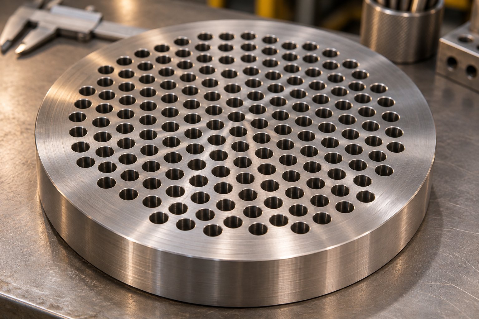
Wrong Extruder Breaker Plate? Spot the Signs Before Scrap Piles Up
Nov 19, 2026
Learn how to select, size, and maintain your extruder breaker plate. Covers hole geometry, pressure drop, polymer-specific specs, and troubleshooting tips.
Read Article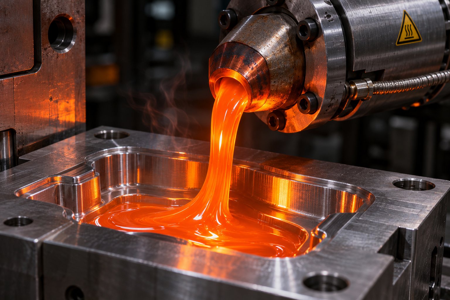
Injection Molding Melt Temperature: Why Your Barrel Settings Lie
Nov 19, 2026
Learn why barrel set points lie about injection molding melt temperature. Complete resin chart, measurement methods, defect troubleshooting, and optimization steps.
Read ArticleLooking for something else?
Search by material, symptom or product and jump straight to the relevant page.
These are navigation suggestions based on keyword matching — not a quotation, not a delivery commitment, and not a substitute for engineering review. Final specification is confirmed by our engineers against your drawings and processed material.
Need help with screw barrel selection?
Share your machine model, processed material and application. Our team can help with pricing and technical support.