

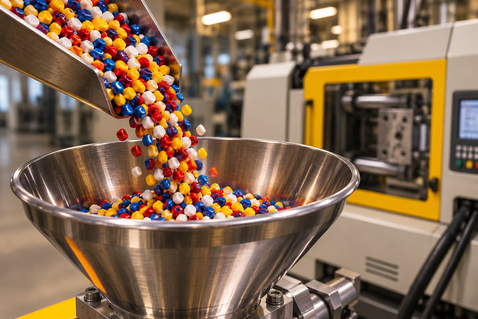
What Injection Molding Color Mixing Actually Involves
Injection molding color mixing is the process of dispersing colorant uniformly into a polymer melt inside the plasticizing unit so that every molded part exits with consistent hue, opacity, and surface appearance. It sounds straightforward. In practice, it is one of the most underestimated variables on the production floor — sitting at the intersection of material science, machine mechanics, and process engineering, yet treated by many operators as a set-it-and-forget-it detail inherited from the last shift.
Why does that matter? Because an injection molding color change gone wrong does not just produce ugly parts. It generates scrap, triggers customer rejections, and stalls shipments. And unlike a dimensional issue you can measure with calipers in seconds, color inconsistency often creeps in gradually, undetected until an entire run fails final inspection.
This article is built for the people who actually solve these problems: process engineers, tooling managers, and quality teams who need actionable depth rather than surface-level overviews. You will find detailed guidance on colorant types and selection, a side-by-side comparison of every major mixing method, the role screw geometry and barrel condition play in pigment dispersion, process parameter tuning for color quality, resin-specific compatibility guidance, defect troubleshooting workflows, and a practical color QC protocol grounded in spectrophotometry.
Defining Color Mixing in the Plasticizing Process
At its core, color mixing is a two-part challenge. First, pigment agglomerates — clusters of colorant particles that arrive bonded together — must be physically broken apart. This is dispersive mixing, and it demands shear energy from the screw and melt. Second, those now-separated particles must be spread evenly throughout the entire melt volume. This is distributive mixing, the process that ensures one region of the shot is not darker or lighter than another.
Both stages must happen within the short residence time of a typical injection cycle, often just seconds of active screw rotation during recovery. Research from Paderborn University using 3D CFD flow simulations and particle tracking confirms that screw element geometry and rotation speed have a significant influence on both dispersive and distributive mixing outcomes — and that the two mixing types respond differently to the same hardware and process changes. In other words, a screw configuration that excels at breaking agglomerates may not distribute them well, and vice versa.
When you think about injection molding color mixing this way — as a dispersion and distribution problem governed by shear stress, residence time, and melt viscosity — the path to diagnosing and solving color defects becomes far more logical.
Why Color Consistency Is a Production-Critical Variable
Imagine opening a carton of consumer electronics housings and spotting three slightly different shades of the same blue. Or picture an automotive interior panel that does not quite match the dashboard it sits beside. Color is evaluated instantly, intuitively, and unforgivingly.
Color is the first quality attribute a customer evaluates — before dimensional checks, before mechanical testing.
In industries where Delta E tolerances are tight — automotive applications often demand CMC values of 0.5 or less, while consumer products typically allow Delta E under 2.0 — even minor drift in the injection molding plastic colorant compound can push parts out of specification. The consequences cascade quickly: quarantined inventory, sorting labor, re-molding costs, and strained customer relationships.
Multi color injection molding projects amplify this pressure further, because each color region must match its own standard while harmonizing visually with adjacent colors on the same part. The margin for error shrinks with every additional hue.
Color consistency is not a cosmetic luxury. It is a production-critical variable that demands the same engineering rigor applied to dimensions, gate locations, and cooling circuits. The sections that follow break down exactly how to achieve it — starting with the colorants themselves.
Understanding Colorant Types From Dyes to Inorganic Pigments
Every plastic colorant for injection molding falls into one of two fundamental categories — and confusing them leads to processing headaches that no amount of parameter tuning will fix. The distinction between pigments and dyes is not just academic vocabulary. It determines how the colorant interacts with your polymer, what kind of mixing energy it requires, and which defects you are most likely to encounter.
Pigments Versus Dyes and When Each Applies
Dyes are organic compounds that dissolve into the polymer matrix, much like sugar dissolving in water. Because they lose their particulate structure entirely, dyes have virtually no effect on light transmission through the plastic — making them ideal when you need bright, transparent, or translucent mold in color results. Think crystal-clear polystyrene drinkware or transparent styrenic display cases where vibrancy and clarity matter most.
The trade-off? Dyes offer limited heat stability and are prone to migration — they can bleed to the surface or transfer into adjacent materials over time. As Scott Sabreen of The Sabreen Group notes, dyes have low solubility in polyethylene and polypropylene and tend to migrate out, making them a risky choice for polyolefins and most engineering resins. Their practical use is largely confined to certain amorphous thermoplastics where processing temperatures stay moderate.
Pigments, by contrast, are solid particles that remain insoluble in the polymer. They must be physically dispersed — broken apart and spread throughout the melt by mechanical shear. This demand for dispersive energy is exactly why screw geometry and back pressure matter so much when working with pigmented systems. Pigments reward that effort with broader chemical resistance, superior opacity, and far better migration resistance than dyes can offer.
Organic and Inorganic Pigments Compared
Within the pigment category, the organic-versus-inorganic split drives nearly every downstream processing and performance decision. Organic pigments — compounds like phthalocyanine blues and quinacridone reds — deliver exceptionally high tinting power from small particle sizes. You need less material to achieve vivid, saturated color. However, their smaller particles can be harder to wet out, and their thermal ceilings are lower.
Inorganic pigments — titanium dioxide (white), iron oxides (reds, yellows, blacks), and carbon black — provide outstanding opacity, heat resistance, and UV stability. They are workhorses in demanding applications but typically require higher loadings to reach the same color intensity as their organic counterparts.
The table below summarizes how these two families compare across the properties that matter most when selecting an in mold color system:
| Property | Organic Pigments | Inorganic Pigments |
|---|---|---|
| Heat Stability | Moderate — many degrade above 250-280°C | High — stable well above 300°C |
| Color Strength / Tinting Power | High — vivid color at low dosages | Lower — requires higher loading levels |
| Opacity | Low to moderate — often translucent | High — excellent hiding power |
| Lightfastness (UV Resistance) | Variable — ranges from poor to good | Generally superior |
| Migration Resistance | Lower — some grades prone to bleed | High — virtually no migration |
| Cost | Varies widely by chemistry | Varies — TiO₂ can be costly at high loadings |
| FDA / Food-Contact Suitability | Limited — select grades only | Preferred — many grades approved |
A quick rule of thumb: if your application involves high processing temperatures, outdoor UV exposure, or food-contact compliance, inorganic pigments are almost always the safer starting point. When maximum color brilliance at low concentration is the priority — and thermal demands are moderate — organic pigments earn their place.
How Colorant Chemistry Affects Processing Decisions
Here is the point many color discussions miss entirely: choosing a colorant is not purely an aesthetic decision. It directly constrains your process window. Each pigment chemistry carries a unique processing envelope — a combination of maximum barrel temperature, required shear energy for dispersion, and carrier resin compatibility demands.
Consider a practical example. Phthalocyanine blue pigments are among the most thermally robust organics, tolerating temperatures well above 300°C, so they work in polycarbonate and nylon applications where many other organic pigments would degrade and shift color. Iron oxide reds handle heat beautifully but have low tinting strength, meaning higher pigment loadings that can affect melt viscosity if not accounted for. Titanium dioxide is indispensable for white and pastel shades, yet its relatively coarse particle size makes dispersive mixing — not distributive mixing — the dominant challenge.
Carrier resin compatibility adds another layer. A masterbatch formulated with a polypropylene carrier will not disperse cleanly in a polyethylene matrix — and the reverse is equally problematic. AIMPLAS research emphasizes that pigment yield is closely linked to dispersion quality, which itself depends on particle size, polymer viscosity, processing conditions, and chemical compatibility between colorant and matrix. Poor compatibility does not just reduce color intensity; it wastes material and introduces defects.
Dispersion aids included in color formulations — typically metal soaps like zinc stearate or ethylene bisstearamide (EBS) wax — further influence processing. These additives improve pigment wetting and distribution, but in non-polar resins like PE and PP, they can migrate to the part surface and interfere with downstream bonding or printing operations. Recognizing this upfront lets you specify alternative dispersants before problems surface in production.
The takeaway is straightforward: colorant chemistry sets boundary conditions for barrel temperatures, screw mixing demands, carrier selection, and even secondary processing compatibility. Selecting the right plastic colorant for injection molding before dialing in a single machine parameter saves far more time than troubleshooting a mismatch after the fact — which is exactly why the next step is understanding how each coloring method delivers that colorant into the melt.
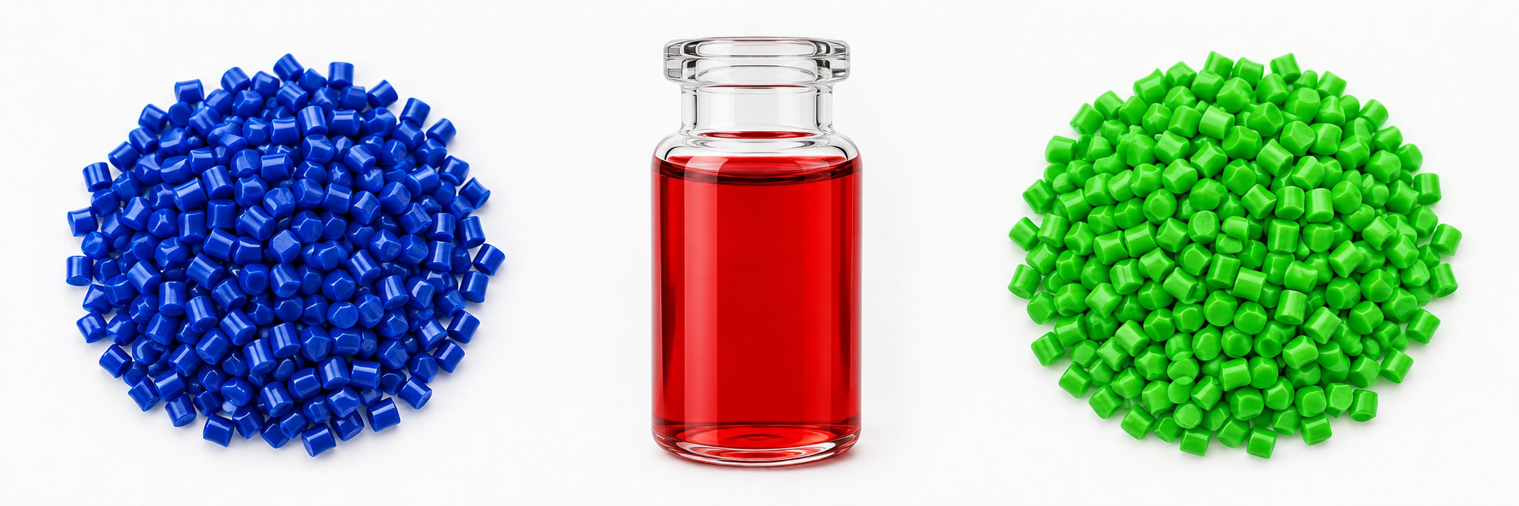
Comparing Every Color Mixing Method for Injection Molding
Knowing your colorant chemistry is only half the equation. The method you use to introduce that colorant into the polymer melt shapes everything from part-to-part consistency to changeover downtime, scrap rates, and per-unit cost. Yet most molding operations default to whichever method the previous engineer set up — without evaluating whether it still fits the job.
Six distinct approaches dominate color injection molding today. Each carries a different profile of cost, consistency, equipment demand, and operator complexity. Choosing the wrong one does not just create injection molding color mixing problems — it bakes inefficiency into every cycle.
Six Color Mixing Methods Ranked by Key Decision Factors
Before diving into the details, it helps to see all six methods side by side. The table below ranks each approach across the factors that drive real-world selection decisions on the shop floor:
| Method | Cost Per Part | Color Consistency Achievable | Equipment Required | Changeover Time | Minimum Run Size Suitability | Operator Skill Level |
|---|---|---|---|---|---|---|
| Pre-Colored (Compounded) Resin | High | Highest | None beyond standard | Moderate — purging needed | Large runs only | Low |
| Masterbatch (Color Concentrate) | Low to Medium | High | Dosing feeder (volumetric or gravimetric) | Low to Moderate | Medium to large runs | Low to Medium |
| Liquid Colorant | Low to Medium | High | Metering pump, hoses, pump controller | Moderate — equipment cleaning | Medium to large runs | Medium to High |
| Dry Pigment / Powder | Lowest | Low to Medium | Tumble blender or hopper mixer | Low | Small to medium runs | High |
| Salt-and-Pepper Blending | Low | Medium | Blender or manual mixing | Low | Small runs | Medium |
| Custom Compounding | Medium to High | Highest | Twin-screw compounder (outsourced or in-house) | High — new compound required | Large runs only | Low (at press) |
Notice the pattern: methods that shift complexity away from the press operator — pre-colored resin and custom compounding — deliver the tightest consistency but demand higher material costs and longer lead times. Methods that push mixing responsibility onto the plasticizing unit — dry pigment, salt-and-pepper blending — cost less per pound but introduce more variability and require sharper operator judgment.
Masterbatch Versus Liquid Color Versus Pre-Colored Resin
These three methods account for the vast majority of production-scale color injection molding. Understanding their trade-offs is essential for any color control strategy.
Masterbatch — concentrated pigment dispersed in a carrier resin pellet — is the workhorse of the industry for a reason. Dosed at a typical letdown ratio of 1-5% into natural resin, it balances cost, changeover flexibility, and color consistency well enough for most medium-to-large production runs. You store natural resin in bulk and keep a library of masterbatch colors on hand, switching between them with relatively short purge cycles. The key requirement is a reliable dosing feeder mounted at the feed throat to meter the correct proportion of concentrate into every shot.
Liquid colorant systems take a different approach. Pigment is suspended in a liquid carrier and metered into the feed throat or directly onto the screw via a precision pump. Because the carrier is already fluid, liquid color achieves excellent dispersion at lower letdown ratios — sometimes below 1%. This makes it particularly effective for tints, transparent effects, and pearlescent or metallic finishes where uniform pigment distribution is critical.
However, liquid color carries operational baggage that the spec sheet does not always reveal. Specialized pumps and polyethylene delivery tubes are required, and those tubes are consumables that wear and can rupture, causing spills. If a production line stops and the pump is not tied into the screw signal correctly, it keeps dosing — flooding the barrel. Liquid containers can empty without warning, forcing unplanned downtime. Extended use can stain the screw, and the liquid itself has a limited shelf life with separation issues. Scrap rates associated with liquid systems can reach up to 10% due to material that cannot be fully extracted from containers. Regrind fines mixed with residual liquid can also create clumps that block the feed throat.
Pre-colored (compounded) resin eliminates nearly all of these mixing variables at the press. The colorant is already uniformly dispersed throughout the pellet during a prior compounding step, so the injection molding machine simply melts and injects a ready-made material. Consistency is the highest achievable, and operator dependency is minimal. The downsides? Higher material cost per pound, minimum order quantities from the compounder, and lead times that can stretch to weeks for custom colors. For high-volume, single-color programs — especially in automotive or medical applications where Delta E tolerances are unforgiving — the premium is often justified.
Letdown Ratios and Why They Matter More Than Operators Realize
Imagine two operators running the same masterbatch on the same press. One sets the feeder to deliver a 2% letdown ratio; the other dials in 4%. The parts look visibly different — and neither may match the approved color standard. This is why the letdown ratio deserves far more attention than it typically receives.
The letdown ratio is simply the proportion of colorant concentrate to natural resin by weight. It is the single most accessible variable for controlling color intensity, shot-to-shot consistency, and colorant cost per part. Getting it wrong creates problems in both directions:
- Under-dosing produces weak, washed-out color and amplifies shot-to-shot variation because small fluctuations in feeder output represent a larger percentage of an already-low target.
- Over-dosing wastes expensive colorant, can shift color beyond the high end of the tolerance window, and may degrade mechanical properties of the base resin. Excess pigment can also cause plate-out — a film of colorant buildup on the mold surface that transfers to parts and escalates cleaning downtime.
How accurately you hit that target depends heavily on your feeding equipment. Volumetric feeders dispense a set volume of material per unit time based on displacement. They are simpler and less expensive, but they cannot compensate for density variations in the masterbatch, hopper level changes, or pellet size differences. When the material flow shifts — say, when a fresh bag of masterbatch has a slightly different bulk density — the actual weight delivered drifts, and color shifts with it.
Gravimetric feeders measure the actual weight being dosed using a load cell and automatically adjust motor speed to maintain the target. As loss-in-weight dosing systems demonstrate, self-calibrating gravimetric technology eliminates the manual speed adjustments that volumetric feeders require, reducing the risk of overdosing and saving cost on expensive additives over time. The initial equipment investment is higher, but the return on investment builds with every shift of tighter color control and reduced colorant waste.
For color control plastic molders pursuing Delta E tolerances below 2.0, gravimetric dosing is not a luxury — it is a practical necessity.
A Method Selection Decision Framework
With six methods on the table, how do you choose? Rather than defaulting to habit, walk through a simple decision sequence tailored to your production reality:
- What is your annual volume for this color? If you are running hundreds of thousands of parts in a single color, pre-colored resin or custom compounding delivers the best consistency with the least per-part risk. For lower volumes or frequent color changes, masterbatch or liquid color keeps inventory lean.
- How many color changes per shift? Multiple changeovers favor masterbatch for its relatively quick purge cycles. Liquid color changeovers involve pump and hose cleaning that extends downtime. Pre-colored resin changes require full hopper and barrel purges.
- What is your acceptable Delta E tolerance? Tight tolerances (below 1.0) push you toward pre-colored resin or masterbatch with gravimetric dosing. Wider tolerances (2.0-3.0) open the door to volumetric dosing or even salt-and-pepper blending for short runs.
- Do you have gravimetric blending equipment? If yes, masterbatch becomes a high-consistency option across a wide range of volumes. If you are limited to volumetric feeders, consider whether the dosing variability fits within your color specification — or whether investing in gravimetric equipment pays for itself through reduced scrap and colorant savings.
No single method wins in every scenario. The multi color injection molding process, for instance, often combines pre-colored resin for the primary shot with masterbatch for secondary overmold colors — leveraging the strengths of each where they matter most. The goal is not to find a universal answer but to match the method to the specific demands of each program: volume, tolerance, changeover frequency, and available equipment.
Selecting the right coloring method gets the colorant to the feed throat under controlled conditions. What happens next — inside the barrel, under the influence of screw geometry, compression ratio, and flight clearance — determines whether that colorant actually disperses into a flawless melt or survives as streaks waiting to ruin the next batch of parts.
How Screw Design and Barrel Condition Drive Color Dispersion
You could select the perfect pigment, nail the letdown ratio, and invest in a top-tier gravimetric feeder — and still pull streaked parts off the conveyor. Why? Because the plasticizing unit is where color mixing physically happens. The screw, barrel bore, and mixing elements are the hardware that converts rotational energy into the shear and distributive forces your colorant needs. If those components are wrong for the application — or simply worn — no amount of parameter adjustment compensates fully.
This is the topic most injection molding color mixing discussions skip entirely. Yet for process engineers and maintenance teams chasing persistent color defects, it is often the missing piece.
How Screw Geometry Controls Dispersive and Distributive Mixing
Every standard injection screw divides into three functional zones, and each one plays a distinct role in plasticizing unit pigment dispersion:
- Feed zone — deep channels accept solid pellets and colorant granules from the hopper, conveying them forward. Minimal mixing occurs here; the material is still mostly solid.
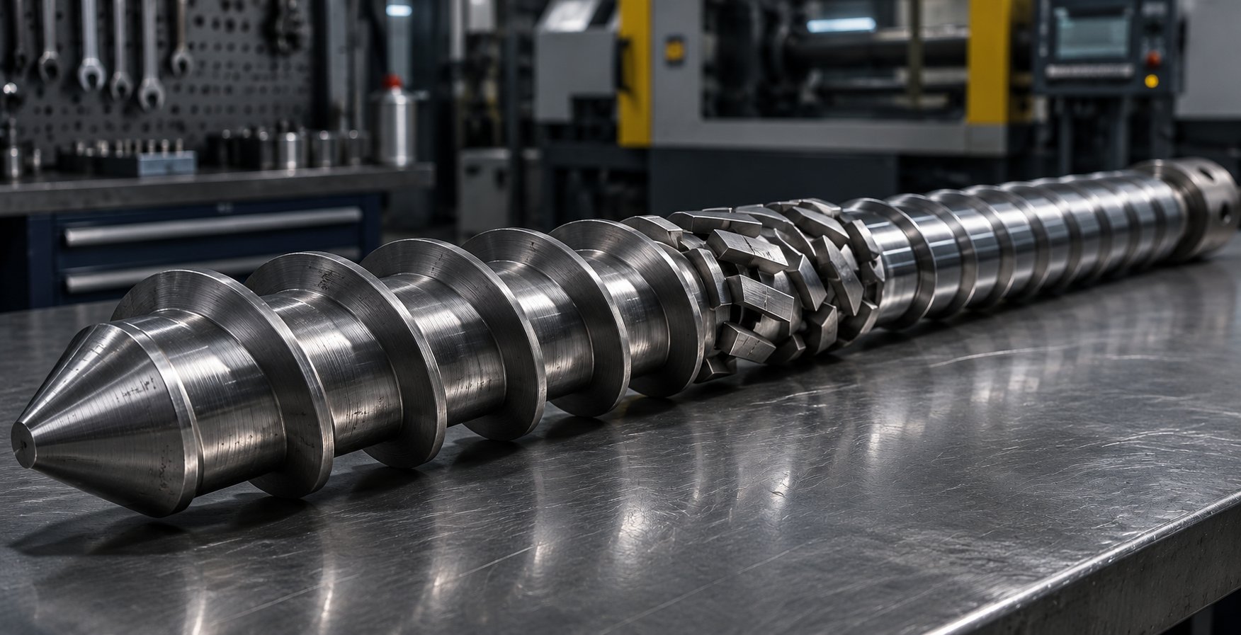
- Compression (transition) zone — channel depth decreases progressively, compressing the material against the barrel wall. This compression generates the conductive heat transfer and mechanical shear that begin melting the polymer and wetting pigment surfaces. The compression ratio — the ratio of feed-zone channel depth to metering-zone channel depth — is the primary geometric variable controlling how aggressively this zone works. Typical packaging screws range from 2.0:1 to 3.0:1, with higher ratios delivering more shear energy to break pigment agglomerates.
- Metering zone — a shallow, constant-depth channel that homogenizes the now-molten polymer and delivers it at consistent pressure to the screw tip. Uniform channel depth here promotes steady output, but on its own, the metering zone provides limited additional mixing.
Higher compression ratios benefit dispersive mixing — the physical breakup of pigment clusters — because the tighter channel forces the melt through a narrower gap at higher shear stress. The trade-off is real, though. Excessive shear generates frictional heat that can thermally degrade heat-sensitive organic pigments, shifting your color in a direction no process sheet predicted. For injection molding screw design for color mixing, the goal is always a compression profile aggressive enough to disperse the pigment but gentle enough to preserve it.
Beyond basic flight geometry, dedicated mixing elements mounted in or after the metering zone dramatically improve both dispersive and distributive performance. Research from Lublin University of Technology studying four different mixing screw element types on a single-screw plasticizing system found that each design influenced the extrusion process differently — without requiring changes to screw speed or temperature settings. Their findings align with what experienced molders observe daily:
- Maddock (fluted) mixers — a series of inlet and outlet grooves separated by barrier flights. The melt is forced over the barrier at high shear, making the Maddock primarily a dispersive mixing element. It excels at breaking apart pigment agglomerates but creates higher pressure drop and can generate localized heat.
- Pineapple mixers — rows of rhomboidal or diamond-shaped protrusions that repeatedly split and recombine the melt stream. This geometry is predominantly distributive, spreading already-dispersed pigment evenly throughout the melt without imposing the high shear stress of a Maddock section.
- Barrier flights — a secondary flight in the transition zone that separates solid and molten polymer channels, accelerating melting efficiency and reducing the chance that unmelted pellets (and the undispersed colorant trapped within them) reach the metering zone.
- Mixing pins and ring mixers — pins or grooved rings that disrupt laminar flow patterns, providing a combination of dispersive and distributive action depending on their geometry and clearance to the barrel wall.
The practical takeaway? A general-purpose screw with no dedicated mixing section relies entirely on the compression zone and metering channel for color dispersion. That may be adequate for pre-colored resin where the colorant is already fully dispersed, but it is often insufficient for masterbatch or dry-pigment methods where agglomerates enter the barrel intact.
When Barrel and Screw Wear Undermine Color Consistency
Imagine this scenario: a mold that ran flawless color for two years gradually begins producing parts with faint streaks. Nothing in the process settings changed. The masterbatch lot is the same. The operator is experienced. What shifted?
The answer is often hiding in plain sight — screw barrel wear color inconsistency. Over thousands of hours of operation, the screw flight outer diameter slowly decreases and the barrel bore gradually increases. Davis-Standard's maintenance guidelines detail how this wear progression is measured: the screw is removed, cleaned with non-abrasive brass tools, and each flight's outer diameter is checked against original specifications using an OD bar micrometer. The barrel bore is similarly gauged. When the clearance between the two exceeds acceptable limits, processing consequences follow.
Why does increased clearance matter for color? Because that gap is where shear energy is generated. A tight flight-to-bore clearance forces the melt to shear intensely as it passes over the flights — exactly the mechanism that breaks pigment agglomerates and drives dispersive mixing. As clearance grows, melt leaks backward over the flights instead of being sheared forward. The result is reduced mixing energy delivered to the colorant, even though screw RPM and back pressure settings remain unchanged.
Wear is not the only hardware culprit. Consider these related failure modes:
- Worn check rings (non-return valves) — a check ring that no longer seats properly allows melt to flow backward during injection, creating inconsistent shot volumes and trapping material that degrades over multiple cycles. That degraded residue introduces discolored specks — a contamination problem that mimics poor color mixing but has an entirely different root cause.
- Dead spots and hang-up areas — scratches, pitting, or corrosion in the barrel bore create pockets where polymer stagnates, thermally degrades, and eventually flushes into the melt stream as dark streaks or black specks. These dead spots also retain previous color during changeovers, extending purge times and causing cross-contamination between runs.
The insidious nature of wear-driven color problems is their gradual onset. A screw does not fail overnight. It loses a few thousandths of an inch per month, and the color shift creeps in so slowly that operators compensate unconsciously — bumping back pressure here, adding screw speed there — until the process window is exhausted and defects become unmanageable.
Matching Plasticizing Components to Mixing Requirements
When troubleshooting confirms that screw or barrel wear is the root cause, the corrective path is mechanical: restore proper flight-to-bore clearance and mixing geometry by replacing the worn components. This is not a speculative adjustment — it directly addresses the physical mechanism that disperses colorant in the melt.
The challenge is that replacement screws are not one-size-fits-all. A screw designed for a general-purpose application may lack the mixing sections your colorant demands. A screw built for a different resin family may have the wrong compression ratio, channel depth, or L/D ratio for your material. Matching the plasticizing components to the specific machine, resin, and mixing requirement is what separates a repair from a genuine upgrade.
This is where manufacturers who engineer screws around the application — rather than stocking generic replacements — provide real value. NANHAIYA's custom injection molding screw barrels, for example, are built around the specific machine specifications, resin characteristics, and shot requirements of each application. Their technical review evaluates screw geometry, existing wear patterns, melting capacity, mixing performance, and material-retention concerns before recommending a configuration. For maintenance teams evaluating a screw replacement or considering a mixing-element upgrade to solve persistent color dispersion issues, that application-specific approach helps ensure the new hardware actually resolves the problem rather than introducing a different set of compromises.
A word of perspective, though: replacing a worn screw solves hardware-driven dispersion problems. It will not fix issues rooted in colorant selection, carrier resin incompatibility, incorrect letdown ratios, or mold design limitations. The most effective troubleshooting treats the plasticizing unit as one variable in a system — a critical one, but not the only one.
With the right screw geometry and barrel condition confirmed, the next lever available to the process engineer is equally powerful and far quicker to adjust: the process parameters themselves — barrel temperatures, back pressure, screw RPM, and injection speed — each of which directly influences how well the hardware can do its job.
Process Parameters That Control Color Quality
Screw geometry and barrel condition set the ceiling for how well your plasticizing unit can mix colorant. Process parameters determine how much of that ceiling you actually reach on any given shift. The distinction matters because hardware changes require downtime, capital approval, and lead time — while barrel temperatures, back pressure, and screw speed sit right on the controller screen, adjustable in seconds. For process engineers troubleshooting injection molding color mixing problems, these settings are the fastest levers available.
The catch? Each parameter involves a trade-off. Pushing one setting to improve dispersion can degrade the colorant, extend cycle time, or introduce a different defect entirely. The practitioner's job is not to maximize any single variable but to find the combination that delivers consistent color within the constraints of cycle time, resin stability, and part requirements.
Barrel Temperature Profile and Its Effect on Pigment Dispersion
Barrel zone temperatures do not just melt plastic. They control melt viscosity — and melt viscosity determines how much shear energy the screw flights can transfer into the colorant during recovery. This relationship is the single most important concept for understanding how barrel temperature profile color consistency are connected.
When temperatures are set too low, the polymer remains highly viscous. That elevated viscosity can actually generate greater shear stress on pigment agglomerates — useful in theory for dispersive mixing. In practice, though, the risk is real: incompletely melted pellets and uneven flow create cold slugs that carry undispersed colorant straight through the metering zone. You end up with streaks not because the shear was weak, but because large portions of the shot never reached a fully molten state where mixing could occur.
Crank temperatures too high, and you face the opposite problem. The melt becomes so fluid that the screw channels cannot generate enough shear to break pigment clusters apart. Think of stirring honey versus stirring water — the spoon does far more mechanical work in honey. A polycarbonate color consistency study published by Plastics Engineering demonstrated this directly: color difference (Delta E) decreased substantially as processing temperature increased from the lowest tested condition, because reduced melt viscosity improved pigment distribution — but temperatures pushed beyond the optimal range reintroduced color variation as polymer and pigment degradation set in.
Heat-sensitive organic pigments add another constraint. Many organic colorants begin to thermally degrade above 250-280°C, and that degradation does not always look like burning. It can manifest as a subtle hue shift — a red that drifts toward brown, a yellow that loses saturation — detectable on a spectrophotometer but easy to miss by eye until cumulative drift triggers a customer rejection.
The practical approach is to profile temperatures so the polymer is fully melted by the end of the transition zone, allowing the metering zone and any mixing elements to work on a homogeneous melt. Avoid pushing metering-zone temperatures higher than necessary, since this is where residence time is longest and thermal degradation risk peaks. If you are running engineering resins above 280°C, confirm that your colorant chemistry can handle the thermal exposure — a quick check with the masterbatch supplier that prevents weeks of troubleshooting later.
Back Pressure and Screw RPM as Mixing Controls
If barrel temperature sets the viscosity stage, back pressure and screw RPM determine how hard the screw works the melt during recovery. Together, they are the most direct injection molding process parameters color quality tools an operator can reach for.
Back pressure is the hydraulic resistance applied against the screw as it rotates backward during plasticizing. Increasing it forces the screw to work the material longer and more intensely before each shot accumulates. The result is extended residence time, greater melt compaction, and improved pigment dispersion — especially when injection molding back pressure color mixing issues like faint streaking are present. As JeekMould's process engineering guide explains, a controlled increase in back pressure makes the screw work the resin more thoroughly, improving color dispersion, additive blending, and shot-to-shot repeatability.
The trade-offs are predictable and manageable if you watch for them. Higher back pressure means longer screw recovery time — and if recovery exceeds cooling time, your cycle extends. It also means more frictional heat added to the melt, which raises actual melt temperature regardless of what the barrel heater setpoints read. For heat-sensitive colorants or resins like POM with narrow processing windows, that extra thermal input can push you into degradation territory without any barrel zone ever exceeding its setpoint.
Screw RPM follows a parallel logic. Faster rotation increases the mechanical energy transferred to the melt per unit time, improving both dispersive and distributive mixing. The same polycarbonate study referenced earlier found that increasing screw speed generally reduced Delta E values — indicating closer agreement with the target color — because higher rotational speed increased shear intensity and promoted more uniform pigment distribution. However, at the highest speeds tested (approximately 800 rpm in the twin-screw extruder used), the improvement plateaued and began reversing as shear-induced thermal input promoted material degradation.
On the shop floor, the practical balancing act looks like this:
- Start with the material supplier's recommended back pressure — typically in the range of 50-100 psi (3.5-7 bar) for most commodity resins.
- When color streaking is visible, increase back pressure in small increments — 25 psi (roughly 1.5-2 bar) at a time.
- After each adjustment, monitor actual melt temperature (not barrel setpoints) to ensure you are not overshooting the colorant's thermal limit.
- Track screw recovery time to confirm it still finishes within the cooling phase of your cycle.
- If back pressure alone does not resolve streaking, increase screw RPM modestly while again watching melt temperature and recovery time.
The goal is the lowest stable back pressure that produces consistent color — not the highest. Overcorrecting wastes cycle time, degrades sensitive materials, and introduces problems that are harder to trace than the original streaking.
Injection Speed, Hold Pressure, and Their Influence on Visible Color
Most color dispersion happens during screw recovery, but the injection and packing phases influence how that color appears on the finished part. Ignoring these settings during color troubleshooting leads to chasing dispersion problems that are actually flow or crystallization effects.
Injection speed controls shear rate at the gate and through thin-wall sections. High-speed injection generates intense shear as the melt squeezes through a narrow gate opening, and that localized shear can disturb the frozen skin layer before it fully forms. The visual result is gate blush — a hazy, whitened, or color-shifted zone immediately downstream of the gate that is particularly common in ABS, PC, and PA parts. Reducing the initial injection speed, increasing gate size, or raising mold temperature near the gate are the standard corrective actions. In multi-cavity molds, gate blush appearing in only certain cavities almost always traces to tooling-side differences — cooling imbalance or gate geometry variation — rather than process settings.
Shear-induced color variation extends beyond the gate. In thin-wall sections where the melt accelerates, flow-aligned pigment particles can create visible orientation lines. Metallic and pearlescent pigments are especially sensitive to this effect because their platelet-shaped particles reflect light differently depending on alignment angle.
Hold pressure and cooling time influence color through a less obvious mechanism: crystallinity. In semi-crystalline resins like PP, PE, and nylon, thicker wall sections with slower cooling develop larger crystalline structures that scatter light differently, making the same pigment concentration appear more opaque or lighter than in thinner, rapidly cooled sections of the same part. Variations in hold pressure that change packing density further modulate this effect. If you notice color differences between thick and thin regions of a semi-crystalline part — and the colorant dosing checks out — crystallinity-driven opacity variation is a likely culprit.
When color variation appears and the root cause is not immediately obvious, working through adjustments in a disciplined sequence prevents wasted effort and overlapping changes that obscure what actually fixed the problem:
- Verify colorant dosing accuracy — confirm the feeder is delivering the correct letdown ratio by weight, not just checking that it is running.
- Check back pressure and screw RPM — these are the primary dispersion controls during recovery.
- Review the barrel temperature profile — ensure the melt is fully plasticized without overheating the colorant.
- Evaluate injection speed at the gate — look for localized blush or shear-induced color shift.
- Confirm consistent cycle time — operator-dependent delays between shots change residence time, melt temperature, and color from shot to shot.
This sequence moves from the most common and easily corrected causes to the more nuanced ones, ensuring you fix the likely culprits before adjusting parameters that could introduce secondary issues.
Process parameters give you real-time control over dispersion quality and color appearance — but they operate within boundaries set by the resin itself. A temperature profile that works beautifully for polypropylene will degrade polycarbonate colorants; a back pressure that disperses pigment in ABS may be dangerously high for POM. The resin-colorant interaction is the next variable that shapes every decision made so far.
Resin-by-Colorant Compatibility for Common Injection Molding Materials
Every barrel temperature profile, back pressure setting, and screw RPM you dial in operates within a window defined by the resin you are running. A colorant that disperses flawlessly in polypropylene at 230°C may thermally degrade in polycarbonate at 310°C. A masterbatch carrier that blends invisibly into ABS can leave visible flow marks in a high-gloss PP part. These are not edge cases — they are everyday realities that account for a surprising share of color rejection reports.
Yet most color mixing discussions treat resin as an afterthought, offering vague reminders to "check compatibility" without explaining what that actually means for each material family. The guidance below fills that gap. It is organized by resin group, covering how each polymer's thermal requirements, crystallinity behavior, and chemical sensitivity shape your colorant and carrier choices on the shop floor.
Polyolefins — PP and PE Color Mixing Considerations
Polypropylene and polyethylene are the highest-volume injection molding resins worldwide, and their relatively low processing temperatures — typically 200-260°C for PP and 180-240°C for PE — make them compatible with a broad palette of both organic and inorganic pigments. Most organic chemistries survive these thermal conditions comfortably, giving you access to vivid, high-chroma colors that higher-temperature resins simply cannot support.
The hidden pitfall with polyolefins is not temperature. It is carrier resin compatibility in masterbatch. PP and PE are both olefins, so it is tempting to assume a masterbatch designed for one works equally well in the other. In practice, the two resins have different crystalline structures and melt behaviors that limit their mutual compatibility. Industry formulation principles confirm this clearly: although polyethylene and polypropylene are both olefins, using a PE-carrier masterbatch in PP injection molding can produce visible flow marks on high-gloss products and affect spinnability in fiber applications. The compatibility gap between these two "similar" resins is real enough that dedicated PP-carrier and PE-carrier masterbatches exist for good reason.
Colorant compatibility polypropylene injection molding also involves a crystallinity factor that catches many teams off guard. PP is semi-crystalline, and the degree of crystallinity that develops in a given wall section depends on cooling rate. Thicker sections cool more slowly, forming larger crystalline structures that scatter light and increase opacity — making the same pigment loading look lighter or more opaque than it does in thin-walled areas. Worse, many colorants act as nucleating agents in polypropylene, changing the crystal structure, shrinkage, and even impact resistance of the base resin. If a color change coincides with unexpected warpage or dimensional shift, colorant-induced nucleation is a strong suspect.
For PE, the same crystallinity sensitivity applies, compounded by the variety of PE grades in play — LDPE, LLDPE, and HDPE each melt at different temperatures and develop crystallinity differently. HDPE's higher crystallinity makes it naturally more opaque, which affects how pigments appear compared to the same loading in LDPE.
Styrenics — ABS, PS, SAN, and ASA
Amorphous styrenics are, in many ways, the easiest resin family to color. Their lack of crystalline structure eliminates the opacity variations that plague polyolefins, and their moderate processing temperatures (200-260°C for most grades) open the door to a wide range of organic and inorganic pigments alike. If you need vibrant, saturated color with sharp visual consistency across the part, styrenics are your most forgiving canvas.
ABS is the standout here for ABS color matching injection molding. Its opaque, ivory-toned base provides a consistent backdrop that pigments layer onto predictably. Color matching is relatively straightforward, and the resin accepts both masterbatch and pre-colored compound formats with excellent results. The risk with ABS lies not in colorant compatibility but in heat history. ABS yellows when it sits too long at processing temperature — prolonged residence time in an oversized barrel, extended cycle interruptions, or excessive regrind with multiple heat cycles all push the base resin toward yellow, shifting every color built on top of it. If you notice a slow color drift over a production run, check your shot-size-to-barrel ratio. A shot that uses less than 40-50% of barrel capacity means the remainder sits at temperature for too long.
PS (polystyrene) is one of the few commodity resins that is truly transparent in its natural state, making it an ideal candidate for dye-based coloring when translucent or crystal-clear tinted effects are desired. Dyes dissolve into the amorphous matrix and maintain optical clarity in ways that pigments — which scatter light — cannot. Just remember that dyes trade brilliance for migration risk and limited heat stability, so they are best reserved for decorative applications without demanding environmental exposure.
SAN and ASA share the amorphous advantage of ABS and PS but bring their own nuances. SAN offers transparency similar to PS with better chemical resistance, while ASA provides the UV stability that ABS lacks — making it the preferred choice for outdoor applications where color retention over years of sun exposure matters.
Engineering Resins — PC, Nylon, POM, PBT
Engineering resins push processing temperatures into territory where colorant survival becomes the primary selection criterion. Many organic pigments that perform beautifully in polyolefins or styrenics simply cannot withstand the thermal exposure required to melt and mold polycarbonate at 290-320°C or nylon at 260-300°C. Choosing the wrong pigment here does not just shift color — it can decompose the colorant entirely, producing off-gassing, surface defects, and mechanical property loss.
Polycarbonate (PC) demands special attention beyond just heat stability. PC is chemically sensitive to certain basic compounds present in pigment carriers. The classic example involves TiO2 (titanium dioxide) white pigments, where hydroxides of aluminum and potassium in the mineral's natural composition are chemically basic. At PC's processing temperatures above 300°C, these basic compounds trigger rapid degradation of the polycarbonate chain. Pigment suppliers address this by surface-treating TiO2 to neutralize the basic constituents — but if you source untreated or improperly treated grades, stress cracking and molecular weight loss follow. This engineering resin pigment selection guide principle applies broadly: always verify that the pigment grade is specifically rated for PC applications, not just "high-heat" in general terms.
Nylon (PA6, PA66) introduces a moisture variable that no other common resin shares to the same degree. Nylon is hygroscopic — it absorbs atmospheric moisture readily — and that moisture creates splay (silver streaking) on the part surface during molding. Splay disrupts surface color uniformity in ways that look like poor pigment dispersion but have nothing to do with the colorant at all. Nylon colorant heat stability molding starts with thorough resin drying — typically 4-6 hours at 80°C for PA6 — before any meaningful color evaluation can occur. If your nylon parts show inconsistent surface color, verify moisture content before touching a single process parameter. Beyond drying, nylon's high processing temperatures (260-300°C) restrict colorant selection to thermally robust pigments. Iron oxides, certain carbon blacks, and specially engineered organics are the go-to choices for high-heat nylon applications.
POM (acetal) presents a narrow processing window — typically 190-210°C — with a sharp degradation cliff. POM releases formaldehyde gas when overheated, creating both a safety hazard and visible porosity in parts. The narrow thermal window actually simplifies colorant selection (most pigments survive these temperatures), but it demands very tight barrel temperature control and minimal residence time. Over-dosing colorant in POM can raise melt viscosity enough to require higher barrel temperatures, pushing the process dangerously close to degradation.
PBT (polybutylene terephthalate) processes in the 240-270°C range and, like nylon, requires pre-drying to prevent hydrolysis that degrades molecular weight and surface appearance. PBT is semi-crystalline, so the same crystallinity-driven opacity variations that affect PP apply here — thicker sections appear different from thinner ones when cooling rates diverge. Carrier resin compatibility matters as well: PBT-based masterbatch carriers or compatible polyester carriers disperse cleanly, while polyolefin-based carriers create visible contamination.
The table below consolidates these resin-specific considerations into a quick-reference format for process engineers evaluating colorant options across their material portfolio:
| Resin Family | Typical Processing Temp Range | Colorant Restrictions | Key Mixing Considerations | Common Pitfalls |
|---|---|---|---|---|
| PP | 200-260°C | Few — wide pigment compatibility | Match carrier resin to PP; crystallinity affects perceived color in thick sections | PE-carrier masterbatch causing flow marks; colorant-induced nucleation changing shrinkage |
| PE (LDPE, LLDPE, HDPE) | 180-240°C | Few — most organics and inorganics suitable | Use PE-carrier masterbatch; HDPE's higher crystallinity increases natural opacity | PP-carrier incompatibility; dye migration in non-polar PE matrix |
| ABS | 220-260°C | Minimal — broad pigment compatibility | Forgiving base for color matching; monitor heat history and regrind levels | Yellowing from prolonged residence time shifting all colors; oversized barrel worsening drift |
| PS | 180-250°C | Dyes suitable for transparent effects; standard pigments for opaque | Transparent base allows dye-based translucent coloring | Dye migration in long-term applications; brittleness limits pigment loading |
| PC | 280-320°C | High-heat-stable pigments only; TiO2 must be surface-treated for PC | Verify pigment chemical compatibility — not just thermal rating | Stress cracking from basic pigment carriers; untreated TiO2 causing degradation |
| Nylon (PA6, PA66) | 260-300°C | Thermally stable inorganics and select engineered organics | Dry resin thoroughly before molding and color evaluation | Moisture-induced splay mimicking poor dispersion; organic pigment degradation above 280°C |
| POM | 190-210°C | Most pigments survive; avoid over-loading | Narrow thermal window — tight temperature control essential | Formaldehyde release on overheating; excess colorant raising viscosity into degradation zone |
| PBT | 240-270°C | Moderate heat stability needed; avoid low-grade organics | Pre-dry resin; use PBT-compatible or polyester-based carriers | Hydrolysis from moisture; polyolefin carrier contamination; crystallinity-driven color variation |
You will notice a pattern running through every row of that table: colorant selection and resin processing are never independent decisions. The pigment chemistry constrains your temperature limits. The carrier resin constrains your masterbatch options. The polymer's crystallinity or moisture sensitivity constrains how the finished color appears — regardless of how well the pigment dispersed in the barrel.
Treating these interactions as a system, rather than checking boxes in isolation, is what separates a consistently color-matched production run from one that lurches between approvals and rejections. And when color does go wrong despite careful material pairing, the defect itself holds diagnostic clues — streaking, shot-to-shot variation, gate blush, or thermal degradation each point toward a different root cause and a different corrective path.
Troubleshooting Common Color Mixing Defects
A flawless color match on the first article plaque means little if defects surface fifty shots later — or show up only in cavity three, or creep in gradually over a two-week production campaign. Color mixing defects are frustrating precisely because they masquerade as each other. A streak caused by worn screw flights looks almost identical to one caused by an incompatible carrier resin. A shot-to-shot color shift from feeder inconsistency can be indistinguishable from one driven by fluctuating barrel temperatures — until you know what to look for.
Effective troubleshooting starts with classification: what type of defect are you seeing, where does it appear on the part, and is it repeatable or random? Those three questions narrow the root cause list dramatically before you touch a single process parameter. The sections below break down the most common injection molding pigment dispersion problems by defect type, trace each to its likely origins, and lay out corrective actions in priority order.
Color Streaking and Poor Pigment Dispersion
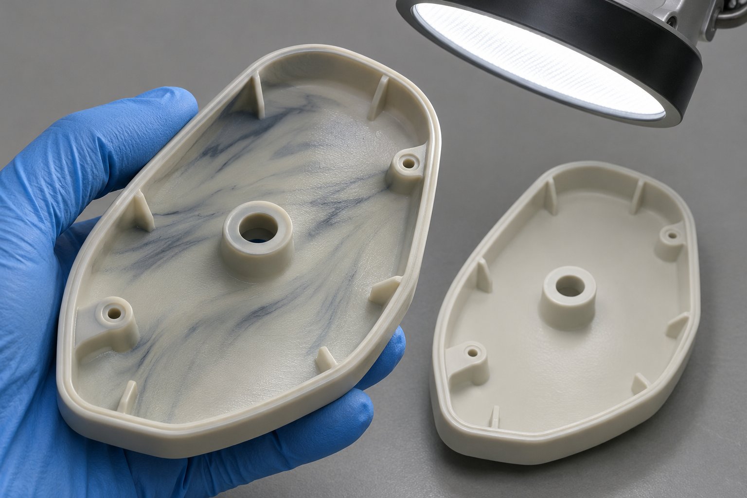
Streaking — visible lines, swirls, or ribbons of concentrated or under-dispersed colorant running through the part — is the single most reported color mixing defect in injection molding. It tells you that pigment agglomerates survived the plasticizing process intact, or that the colorant never distributed uniformly through the melt volume before injection. Either way, the mixing energy delivered during screw recovery was insufficient for the colorant system in use.
The injection molding color streaking causes typically cluster around five root areas, and each one demands a different corrective approach:
- Insufficient back pressure — the most common and easiest to address. Low back pressure allows the screw to recover too quickly, shortening the time the melt spends under shear. Pigment agglomerates pass through the metering zone intact.
- Low screw RPM — reduces the total shear energy applied per recovery stroke. Combined with low back pressure, this creates conditions where even well-formulated masterbatch cannot disperse fully.
- Incompatible carrier resin in masterbatch — as discussed in the resin compatibility section, a PP-carrier masterbatch in PE, or vice versa, resists blending into the base polymer. The carrier remains as distinct domains that show up as streaks, particularly on high-gloss surfaces.
- Incorrect letdown ratio — over-concentrated colorant creates visible swirls of excess pigment, while under-dosed masterbatch produces pale streaks in an otherwise color-saturated matrix.
- Worn mixing sections or excessive flight clearance on the screw — when the screw's mixing elements are worn down or the flight-to-bore clearance has opened beyond specification, the hardware can no longer generate the shear stress needed to break agglomerates. This is the root cause that process adjustments alone cannot fully compensate for.
When streaking appears, work through the corrective steps in this priority sequence — starting with the fastest, least invasive adjustments and escalating only when simpler fixes do not resolve the issue:
- Confirm the letdown ratio is correct by weighing a sample batch of natural resin and masterbatch from the hopper — do not rely solely on feeder display readings.
- Increase back pressure in 25 psi (1.5-2 bar) increments, monitoring melt temperature after each change to avoid thermal degradation.
- Increase screw RPM modestly if back pressure alone does not resolve the streaks, again watching melt temperature and recovery time.
- Verify that the masterbatch carrier resin matches the base polymer — request the carrier resin type from your color supplier if it is not on the technical data sheet.
- Inspect the screw for worn mixing elements and measure flight-to-bore clearance. If clearance exceeds the manufacturer's specification, restoring proper geometry through component replacement directly addresses the dispersion shortfall.
That last point deserves emphasis because it is so frequently overlooked. A screw that has lost even a few thousandths of an inch on its mixing-section flight OD delivers measurably less shear to the melt — and no amount of back pressure increase fully restores what the geometry can no longer provide. When inspection confirms wear as the root cause, NANHAIYA's custom injection molding screw barrels offer an application-specific replacement path: their technical review evaluates the existing screw geometry, wear patterns, and mixing performance against the resin and colorant system in use, then matches the replacement components to the actual dispersion requirement. This is particularly valuable when the original screw lacked dedicated mixing elements to begin with — a common situation on older machines where a mixing-section upgrade, not just a like-for-like replacement, is what the color application truly needs.
Keep the scope honest, though. Screw replacement resolves hardware-driven streaking. If the root cause is carrier incompatibility, incorrect letdown ratio, or a mold-design issue, new hardware will not fix it.
Shot-to-Shot Color Variation and Inconsistency
Streaking is alarming because it is visible on a single part. Shot-to-shot color variation is more insidious — you may not notice it until a batch of parts is lined up side by side under inspection lighting and the gradual drift becomes unmistakable. This type of defect tells you that something in the process is fluctuating between cycles, delivering a slightly different colorant concentration or thermal history to each shot.
The usual suspects behind shot-to-shot color variation in injection molding include:
- Inconsistent dosing from volumetric feeders — as discussed earlier, volumetric feeders dispense by volume, not weight. Changes in masterbatch pellet size, bulk density between bags, or hopper fill level all shift the actual mass of colorant delivered per shot. The variation may be only 0.1-0.2% of letdown ratio — but on a tight Delta E specification, that is enough to push parts in and out of tolerance.
- Regrind ratio variation — regrind that already contains colorant changes the effective letdown ratio when blended back with virgin material. If the regrind percentage fluctuates — say, because an operator adds a different amount each hopper fill — color intensity shifts with it. Regrind also carries a different thermal history than virgin pellets, which can subtly alter color even at the same pigment concentration.
- Fluctuating barrel temperatures — a faulty thermocouple, a heater band with intermittent contact, or a controller tuning issue can cause zone temperatures to oscillate by 5-10°C between cycles. That oscillation changes melt viscosity and shear conditions during every recovery, producing visible color variation. Aprios engineers highlight that temperature fluctuations during processing directly lead to pigment degradation and inconsistent part appearance — making temperature monitoring a frontline diagnostic step.
- Inconsistent cycle times — semi-automatic operation where the operator controls the gate introduces human-paced variability. A three-second delay between one cycle and the next changes residence time in the barrel, which changes melt temperature, which changes both dispersion conditions and thermal exposure on the colorant. Even fully automatic cycles can vary if robot delays or conveyor stalls interrupt the sequence.
- Material lot variation — both resin and masterbatch lots carry manufacturing tolerances. A new bag of natural resin with slightly different melt flow index, or a masterbatch lot with a marginally different pigment concentration, shifts the color baseline. Cavity Mold's troubleshooting guidance reinforces this point: resin or masterbatch lot changes, moisture levels, and dosage all contribute to visible variation even when displayed machine settings remain identical.
The corrective approach for shot-to-shot inconsistency is fundamentally about stabilizing variables rather than changing settings:
- Upgrade to gravimetric dosing if volumetric feeders are introducing unacceptable variation.
- Lock regrind ratios by weight — do not allow operators to eyeball the proportion.
- Verify heater band function and thermocouple accuracy across all barrel zones; replace any components showing intermittent behavior.
- Run in fully automatic cycle mode whenever possible to eliminate operator-paced residence time variation.
- Retain material lot samples and measure incoming color against the master standard before approving new lots for production.
Gate Blush, Weld Line Discoloration, and Thermal Degradation
Some color defects have nothing to do with how well the pigment dispersed in the barrel. They arise from what happens to the melt after it leaves the nozzle — during injection, flow, and cooling inside the mold. Recognizing these flow- and mold-related defects saves you from chasing barrel-side solutions to problems that live on the tooling side.
Gate blush is a localized color shift — often a whitened, hazy, or matte patch — that appears immediately downstream of the gate. It is caused by high shear stress as the melt accelerates through the narrow gate opening during the initial phase of injection. That intense shear disrupts the frozen skin layer and reorients pigment particles at the surface, producing a visible difference from the rest of the part. Gate blush color defect troubleshooting follows a clear corrective path:
- Reduce initial injection speed to lower shear rate at the gate.
- Increase gate cross-section if part design allows — a larger gate reduces the velocity the melt must reach to fill the cavity.
- Raise mold temperature in the gate region to delay skin formation, allowing the melt to flow more smoothly before freezing.
- Adjust melt temperature upward slightly to lower viscosity and reduce the shear stress for a given flow rate.
Weld line discoloration occurs where two or more flow fronts converge and knit together. At the weld, pigment particles — especially platelet-shaped metallics or pearlescents — orient differently than in the surrounding flow-aligned regions. The result is a visible line that differs in color, gloss, or reflectivity from the rest of the surface. Weld lines are fundamentally a tooling and part-geometry issue: gate location, number of gates, and core pins that split flow all determine where weld lines form. Process adjustments like increasing melt temperature or injection speed can improve weld strength and reduce the visual severity, but eliminating the line entirely often requires mold modification — relocating the gate or adding overflow wells that push the weld to a non-cosmetic area.
Thermal degradation of colorants presents differently depending on the pigment chemistry involved. Organic pigments may shift hue — reds drifting toward brown, yellows losing saturation. Inorganic pigments are more thermally robust but can still be affected by degradation of the base resin, which yellows or darkens the matrix the pigment sits within. As noted in MD Plastics' purging guide, degraded resin trapped in barrel dead spots, worn check-ring pockets, or hot-runner manifold corners can release discolored material into an otherwise clean melt stream — creating intermittent dark streaks or specks that appear random.
Signs that thermal degradation is your problem rather than poor dispersion:
- The defect worsens over time during a continuous run, especially after lunch breaks or other interruptions where resin sits at temperature.
- Color shifts toward yellow or brown rather than showing streaks of concentrated pigment.
- Parts from the first few shots after startup look good, but color degrades progressively — indicating cumulative heat exposure.
- Reducing barrel temperatures or shortening cycle time improves the defect, even though dispersion-related streaking would typically worsen under those same changes.
Isolate whether the defect is position-dependent (mold/flow issue) or random (process/material issue) before adjusting parameters.
This diagnostic principle is the single most valuable habit a process engineer can build into their color troubleshooting routine. A color shift that appears in the same spot on every part — near the gate, at a weld line, in a thick section — points to mold geometry, flow conditions, or crystallinity effects. A color shift that moves randomly from shot to shot, or drifts gradually over time, points to material, dosing, or thermal history problems in the barrel. Correctly classifying the defect pattern before making changes prevents the all-too-common cycle of adjusting five parameters at once, getting an ambiguous result, and never truly understanding what fixed the problem — or what broke it in the first place.
Systematic troubleshooting gets you to root cause faster. But even after corrective action, how do you prove the color is right? Visual judgment under shop-floor fluorescent lighting is not reliable enough for production sign-off. Quantifying color with a spectrophotometer and tracking it against a defined standard is what separates reactive firefighting from proactive quality control — and that measurement methodology is its own discipline.
Color Measurement and Quality Control Protocols
Two operators stare at the same molded part under the fluorescent lights above the press. One says the color looks fine. The other says it is too green. Who is right? Without a spectrophotometer and a defined standard, the answer is whoever has more authority — and that is not quality control. It is guesswork wearing a lab coat.
Subjective visual evaluation is where most injection molding color QC protocol failures begin. The human eye is remarkably sensitive to color differences — capable of distinguishing millions of hues — yet remarkably inconsistent as a measurement device. Fatigue, ambient lighting, background color, and even individual color vision deficiency all introduce variability that no amount of training fully eliminates. As X-Rite's quality control specialists emphasize, factors like retinal fatigue, poor color memory, background effects, and lighting conditions can deceive even trained professionals during visual color assessment.
The path from subjective judgment to repeatable, data-driven color QC rests on three pillars: understanding how spectrophotometers quantify color, establishing a physical standard that represents your actual production conditions, and building a sampling protocol that catches drift before it reaches reject limits. Each pillar reinforces the others — skip one, and the system collapses.
Spectrophotometry and Delta E Explained for Molders
A spectrophotometer measures the amount of light a surface reflects at each wavelength across the visible spectrum — roughly 400 to 700 nanometers. Instead of relying on a human observer's impression, the instrument captures a precise reflectance curve that mathematically describes the color. That curve is then converted into coordinates within a standardized color space, most commonly CIE L*a*b* (pronounced "see-lab" or "L-star, a-star, b-star").
Imagine a three-dimensional map. The L* axis runs vertically from black (0) to white (100), representing lightness. The a* axis runs horizontally from green (negative values) to red (positive values). The b* axis runs from blue (negative) to yellow (positive). Every visible color occupies a unique point in this space — and once you have coordinates for two colors, you can calculate the distance between them.
That distance is Delta E — the total color difference between a sample and its reference standard. Think of it as the straight-line distance between two cities on a map: the larger the number, the farther apart the colors. A Delta E of zero means a perfect match. In practical terms:
- Delta E below 1.0 — generally imperceptible to the unaided human eye. This is the domain of laboratory-grade color matching.
- Delta E between 1.0 and 2.0 — noticeable only under careful side-by-side comparison. Many consumer product specifications set their acceptance limit here.
- Delta E above 2.0 — visible to most observers without direct comparison. Automotive interior panels, medical devices, and premium consumer goods typically reject parts at this level or tighter.
Sounds straightforward? There is an important complication. Not all Delta E formulas are created equal, and using the wrong one can cause you to accept bad color or reject good color.
The original formula, Delta E (CIE76), treats color space as perfectly uniform — meaning a shift of one unit in the green-red direction is weighted identically to a one-unit shift in lightness or blue-yellow. The problem is that human perception is not uniform. We are more sensitive to hue shifts than to equivalent changes in chroma or lightness, and our sensitivity varies depending on where in the color space we are looking. A detailed analysis of color tolerance methods explains that the CIE76 rectangular tolerance box often accepts colors that look wrong to the eye while rejecting colors that look perfectly acceptable — because it does not match the elliptical shape of human color perception.
Delta E CMC improved on CIE76 by defining an ellipsoidal tolerance zone that varies in size and shape depending on the color's position in the color space. Colors in the orange region, for example, produce longer, narrower ellipsoids than colors in the green region — reflecting the way human perception actually works. The CMC formula also allows you to adjust the ratio between lightness (l) and chroma (c) tolerance, with a default of 2:1, meaning twice as much variation is permitted in lightness as in chroma. This formula became widely adopted in textiles and has applications in plastics as well.
Delta E 2000 represents the most mathematically advanced formula available and provides the best overall correlation with human visual perception. It refines the weighting factors for hue, chroma, and lightness — and adds a rotation term that corrects for a known perceptual distortion in the blue region of color space. For spectrophotometer color measurement of plastic parts, Delta E 2000 is the most widely recommended formula because it reduces the disagreements between what the instrument reports and what your quality inspector sees.
The practical advice is simple: pick one Delta E formula, specify it clearly in your color specification, and use it consistently for every measurement. Mixing formulas — or converting between them using average factors — introduces errors that defeat the purpose of instrumental measurement.
Setting Up a Color Standard and Avoiding Metamerism Traps
Every spectrophotometer reading is a comparison: your production sample measured against a reference standard. If the standard itself is flawed, every measurement built on it is flawed too — no matter how precise the instrument.
This is why a color standard plaque — a physical sample molded in the actual production resin, at the target wall thickness, using the approved colorant and process — is far more reliable than a Pantone chip, RAL card, or printed swatch for communicating color requirements. A Pantone chip is printed ink on coated paper. Your part is injection molded polypropylene or polycarbonate. The two materials reflect light through entirely different mechanisms, and a spectrophotometer will faithfully quantify that difference. Setting your production target based on a paper standard almost guarantees you will chase a color your material and process cannot physically reproduce.
The ideal workflow is to mold a set of standard plaques during the initial color approval process, measure them instrumentally, and archive both the physical plaque and its L*a*b* data. Store plaques in a dark, temperature-stable environment — UV exposure and heat will shift even stable pigments over months of storage. If your production runs long enough that the standard plaque may degrade, mold replacement standards periodically and cross-reference them against the archived data to confirm they still represent the original target.
Even with a perfect standard plaque, there is a trap that catches experienced quality teams: metamerism. Two color samples can appear to match perfectly under one light source yet look visibly different under another. This happens because the two samples — say, your production part and the approval standard — achieve the same perceived color using different pigment chemistries that reflect light differently across the spectrum. Under daylight, the reflectance curves overlap enough to look identical. Under incandescent store lighting or LED warehouse lights, they diverge.
Konica Minolta's illuminant guide explains the mechanism clearly: metamerism describes a pair of objects that match in color under one lighting condition but not under another, and it commonly occurs when pigments are changed during manufacturing of different parts within one product. In the automotive industry, for instance, a dashboard panel and a center console trim piece may be colored by different suppliers using different pigment systems. Under the D65 daylight illuminant at the assembly plant inspection station, they match. Under the parking lot's metal halide lamps at night, the mismatch becomes obvious — and the customer notices.
Metamerism prevention in plastic color matching requires two measures:
- Evaluate color under multiple illuminants. The primary measurement should use Standard Illuminant D65 (average daylight including UV, correlated color temperature of 6504K), which is the most common reference for industrial color evaluation. A secondary illuminant — Standard Illuminant A (incandescent, 2856K) or an F-series fluorescent illuminant — should also be checked. If the sample and standard match under D65 but diverge under Illuminant A, you have a metameric pair and need to address the pigment chemistry mismatch before production.
- Specify illuminants in the color specification. Do not leave lighting conditions to assumption. Your color specification document should state which primary and secondary illuminants will be used for evaluation, eliminating disputes between your quality team and your customer's incoming inspection.
Using a standardized light booth with selectable D65, Illuminant A, and fluorescent settings for visual confirmation — alongside instrumental measurement — gives you the most robust defense against metamerism-related rejections.
Building a Production Color QC Protocol
Instruments and standards are tools. A protocol is what turns those tools into a system that catches problems before they reach your customer. Too many molding operations measure color at first article approval and then never measure again until a complaint arrives — by which point thousands of out-of-spec parts may have shipped.
A practical injection molding color QC protocol does not require a dedicated lab or a color scientist on staff. It requires a defined workflow that your quality technicians follow consistently, shift after shift. Here is a sequence that works across production scales:
- Establish a master color standard plaque in production resin. Mold it at the target wall thickness, on the production tool if possible, using the approved colorant at the specified letdown ratio. Measure it with your spectrophotometer under D65 and record the L*a*b* values as your numerical reference. Store the physical plaque away from light and heat.
- Define Delta E tolerance per customer specification. Confirm which Delta E formula (CIE76, CMC, or 2000) applies. If the customer does not specify, default to Delta E 2000 — it provides the best correlation with human visual assessment. Document the pass/fail threshold (for example, Delta E 2000 less than 1.5) and ensure every operator and inspector knows it.
- Measure first articles against the standard under D65 illuminant. Before releasing a production run, mold a small sample at stable process conditions and measure it against the master plaque. If Delta E exceeds the tolerance, do not adjust arbitrarily — use the L*a*b* breakdown to diagnose which axis is out (too dark/light, too red/green, too yellow/blue) and trace that shift to its process or material source.
- Set a sampling frequency during production. The right frequency depends on your tolerance tightness, run length, and historical stability. A common starting point is one measurement per hour of continuous production, or one per every 500 parts — whichever comes first. Tighten the frequency during startup, after material lot changes, or when regrind ratios shift.
- Document and trend Delta E values over time to catch drift before it reaches reject limits. A single measurement tells you whether one sample passes. A trend chart tells you whether your process is moving toward failure — giving you time to intervene. If you measure Delta E 2000 values of 0.6, 0.8, 0.9, 1.0, and 1.1 across five consecutive checks against a limit of 1.5, the individual readings all pass, but the trend is unmistakable: something is drifting. Investigate now, not after the next reading lands at 1.6.
The discipline of trending is what separates reactive quality inspection from proactive quality control. Plotting Delta E over time alongside key process variables — barrel temperatures, back pressure, feeder output, regrind percentage, and material lot numbers — creates a diagnostic map that lets you correlate color shifts to their causes in hindsight. Over months, this data builds institutional knowledge that new operators can learn from and that engineering teams can use to tighten incoming material specifications or justify equipment upgrades.
Color measurement transforms injection molding color consistency from an opinion into a number — and from a number into a trend you can manage. It closes the loop between all the upstream decisions covered in earlier sections: colorant selection, mixing method, screw hardware, and process parameters. Each of those variables produces a measurable outcome on the spectrophotometer, and each can be traced, adjusted, and verified through the QC protocol.
Standard single-color parts are demanding enough. When the design calls for multiple colors on the same part — or for specialty pigments like metallics and pearlescents that behave unlike anything conventional — the measurement and mixing challenges multiply in ways that deserve their own focused discussion.
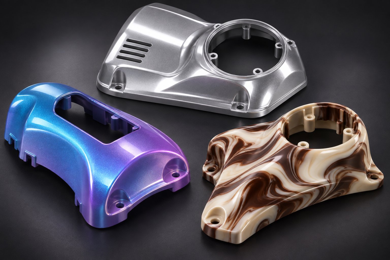
Multi-Color and Specialty Color Techniques Beyond Standard Mixing
Everything discussed so far assumes a single colorant dispersed uniformly into a single resin — the bread and butter of injection molding color mixing. But what happens when the design spec calls for two distinct colors on the same part? Or when the customer wants a metallic finish that shifts in the light? Or a marble-swirl pattern where no two parts look exactly alike?
These applications push well beyond the capabilities of standard single-shot mixing. They introduce specialized tooling, multi-barrel machine configurations, and pigment geometries that respond to flow conditions in ways conventional spherical pigments never do. The aesthetic possibilities are striking — and so are the process challenges hiding behind them.
Multi-Shot Molding, Co-Injection, and Overmolding for Color Combinations
When a part requires sharply defined regions of different color — think a two-tone automotive knob, a soft-touch grip on a rigid tool housing, or a medical device with color-coded zones — no single-shot mixing method can deliver. The colors must remain physically separated, each occupying its intended area with clean boundaries and no bleed-through. That demands multi-material molding techniques.
Multi-shot (2K, 3K) injection molding uses sequential injection of different colored resins into a single mold to create parts with distinct color regions molded in one continuous process. A typical two-shot setup involves a mold with two stations sharing the same platen — the first shot forms one color region, then the mold rotates (via rotary platen) or the part transfers (via robotic arm) to a second station where the second color is injected around or adjacent to the first. The two materials bond chemically and physically during the process, producing an integrated component that would otherwise require assembly of separate parts.
Imagine the design freedom this unlocks. Multi shot injection molding color combinations can incorporate rigid and flexible materials, opaque and translucent sections, or contrasting hues — all in a single molded part with no adhesive joints, no snap-fit assembly, and no secondary painting. The trade-off is in the tooling and machinery: rotary platens, multi-barrel injection units, or robotic transfer systems add capital cost and complexity. Mold design must account for precise alignment between shots, shrinkage of the first material before the second arrives, and bonding compatibility between the resins.
Co-injection (sandwich molding) takes a fundamentally different approach. Instead of placing colors in separate regions, co-injection layers them. A skin material and a core material are injected sequentially through the same gate into the same cavity. The skin material enters first and coats the mold walls, followed by the core material that fills the interior. The result is a part with one color on the outside and a different material hidden inside — useful for burying regrind or recycled content beneath a cosmetically perfect surface, or for combining expensive specialty color on the skin with cost-effective filler in the core.
The two color overmolding process bridges the gap between multi-shot and traditional assembly. Here, a fully molded first-shot part (or a metal insert, or a pre-existing substrate) is placed into a second mold, and a different colored material is injected over or around it. Unlike true two-shot molding where both materials are injected in the same machine cycle, overmolding treats the first component as a finished substrate. Bonding depends on thermal compatibility — the second shot must partially remelt the substrate surface to achieve adhesion — and on chemical affinity between the resin pairs. Not every combination works. PP overmolded onto PA, for example, will typically delaminate because the two resins lack the molecular compatibility to form a reliable bond without adhesion-promoting tie layers.
Each technique delivers multi-color results that no amount of single-shot mixing can replicate. The choice between them depends on your part geometry, production volume, capital equipment, and whether the color boundary needs to be knife-sharp (multi-shot) or layered (co-injection).
Metallic, Pearlescent, and Specialty Pigment Challenges
Conventional pigments are roughly spherical particles. They scatter and reflect light more or less uniformly regardless of how they orient in the melt. Metallic and pearlescent pigments play by entirely different rules — and those rules turn familiar process parameters into critical appearance variables.
Metallic pigments are typically aluminum flakes — platelet-shaped particles that are dramatically wider than they are thick. Research published in Polymers studying flake line defects in metallic injection molding describes these aluminum flakes as having an average diameter of 60 micrometers with a thickness of only 0.6 micrometers — a 100:1 aspect ratio. Pearlescent pigments share this platelet geometry, using thin layers of mica or synthetic substrates coated with metal oxides to create iridescent, color-shifting effects.
Why does shape matter so much? Because platelets orient with flow. Near the mold wall, high shear rates align the flakes parallel to the surface, producing a bright, uniform metallic luster. In the core layer, lower shear rates allow more random orientation. Where flow fronts converge — at weld lines, behind ribs, or downstream of core pins — the disrupted flow creates zones where flakes tilt at irregular angles. The same research confirmed that these velocity differences between surface and core layers cause flakes to adopt non-uniform orientations, producing visible flake line defects that degrade reflectivity and create streaks or patches of uneven gloss.
The metallic pigment injection molding challenges this creates are profoundly different from those of standard color mixing:
- Gate location becomes a cosmetic variable. The area immediately around the gate experiences the most complex flow transitions — high initial velocity, fountain flow, and rapid skin formation. Flake orientation near the gate rarely matches the rest of the part, often producing a visible halo or starburst pattern.
- Runner design influences visible appearance. Unbalanced runners deliver different flow rates and shear histories to different cavities, creating cavity-to-cavity appearance variation that standard pigments would never reveal.
- Injection speed has outsized impact. Faster injection increases shear near the mold wall, improving surface flake alignment and boosting luster — but it also amplifies the velocity difference between surface and core layers, which can intensify flake line defects at flow convergence zones.
- Pearlescent color injection molding flow lines become especially visible because the iridescent effect depends on viewing angle. A flow line that merely looks like a faint streak with standard pigment becomes a dramatic contrast line with pearlescent flakes, as the misaligned particles shift color or lose their characteristic shimmer entirely.
Translucent and color-shifting effects compound the difficulty further. When light penetrates the part rather than reflecting only from the surface, wall thickness variation becomes visible as color intensity variation. A section 0.5 mm thicker than its neighbor absorbs and transmits light differently, producing a noticeable change in hue or saturation that no process adjustment can correct — only tool modification to equalize wall thickness resolves it.
For process engineers tackling metallic or pearlescent projects, the key mindset shift is this: the standard troubleshooting hierarchy — dosing, back pressure, temperature, speed — still applies, but mold design and gate placement move up in priority dramatically. You cannot fix a flake orientation problem at a weld line by increasing back pressure. You fix it by relocating the gate to move the weld to a non-cosmetic surface, or by adding overflow wells that push disoriented flakes out of the visible area.
Intentional Marbling and Color Swirl Effects
Every section of this article so far has focused on achieving uniform color dispersion. Marbling flips that goal on its head. Instead of eliminating variation, you deliberately create it — producing parts with organic, flowing patterns that mimic natural stone, woodgrain, or abstract art.
The basic technique is controlled under-mixing. By reducing the mixing energy the screw delivers during recovery, you allow two or more colored resins to coexist in the melt as distinct but intertwined streams rather than blending into a homogeneous mass. Practical marbling setups typically involve feeding two differently colored resins — or a base resin plus a contrasting masterbatch — through separate injection units into a co-injection manifold. By adjusting injection timing, shot volume ratios, and switch-over points, engineers can influence whether the pattern appears as gentle gradients, bold swirls, or dramatic wave-like contrasts.
Common process adjustments for marbling include:
- Reducing back pressure — limits the mixing energy applied during screw recovery, preserving distinct color domains in the melt.
- Lowering screw RPM — reduces the number of shearing passes the material experiences, maintaining visible color separation.
- Manipulating injection sequence — simultaneous injection of both colors produces softer, more blended marbling textures, while alternating injection pulses create bolder, more dynamic swirl patterns with higher contrast.
The honest reality about marbling? Repeatability is inherently limited. Each shot produces a unique pattern because the exact flow behavior of two incompletely mixed melt streams varies slightly from cycle to cycle. You can control the general character of the pattern — fine versus coarse, high-contrast versus subtle — but not the precise location of every swirl. Most manufacturers position this as a feature rather than a limitation: each part carries a one-of-a-kind visual identity, much like natural marble or terrazzo.
This characteristic makes marbling best suited for decorative applications where uniqueness is valued — furniture components, consumer product housings, cosmetic packaging, and architectural fixtures. It is a poor fit for applications where every part must look identical to its neighbor under inspection lighting. If your customer requires a Delta E tolerance, marbling is probably not the right technique — by definition, no two parts will measure the same.
Across all the techniques covered here — multi-shot molding, metallic and pearlescent pigments, and intentional marbling — a common thread runs through: success depends on understanding how the melt moves, how pigment particles orient within that flow, and how tooling geometry shapes both. The injection molding color mixing fundamentals explored throughout this article — dispersive and distributive mixing, screw geometry, process parameter trade-offs, resin compatibility, and instrumental measurement — remain the foundation. These specialty techniques simply raise the stakes, demanding tighter integration between material science, mold engineering, and process control to achieve results that standard coloring methods cannot reach.
Frequently Asked Questions About Injection Molding Color Mixing
1. What causes color streaking in injection molded parts?
Color streaking typically results from pigment agglomerates surviving the plasticizing process without fully dispersing. The five most common root causes are insufficient back pressure during screw recovery, low screw RPM reducing shear energy, an incompatible carrier resin in the masterbatch (such as using a PE-carrier concentrate in a PP matrix), an incorrect letdown ratio, and worn mixing elements or excessive flight-to-bore clearance on the screw. Corrective action should start with verifying dosing accuracy by weight, then incrementally increasing back pressure while monitoring melt temperature, before escalating to hardware inspection. When screw wear is confirmed, manufacturers like NANHAIYA offer custom injection molding screw barrels engineered to restore proper mixing geometry for the specific resin and colorant system in use.
2. What is the difference between dispersive and distributive mixing in injection molding?
Dispersive mixing and distributive mixing address two distinct stages of colorant incorporation. Dispersive mixing is the process of breaking apart pigment agglomerates — tightly bonded clusters of colorant particles — using shear energy generated between the screw flights and barrel wall. Distributive mixing then spreads those separated particles evenly throughout the entire melt volume so no region is more concentrated than another. Both must occur within the brief residence time of a single screw recovery stroke. Importantly, hardware that excels at one type does not automatically perform the other well. Maddock fluted mixers, for example, are primarily dispersive elements, while pineapple mixers are predominantly distributive. Achieving flawless color often requires a screw configuration that addresses both stages in sequence.
3. How does back pressure affect color quality in injection molding?
Back pressure is the hydraulic resistance applied against the screw during plasticizing recovery. Increasing it forces the screw to work the polymer melt longer and more intensely before each shot accumulates, which extends residence time, improves melt compaction, and delivers greater shear energy to pigment particles. This directly enhances both dispersive and distributive mixing, making it the frontline process adjustment for resolving faint color streaking. However, higher back pressure also generates additional frictional heat and lengthens screw recovery time. For heat-sensitive colorants or resins with narrow processing windows like POM, excessive back pressure can push actual melt temperature into a degradation zone — even when barrel setpoints appear safe. The recommended approach is to start at the resin supplier's baseline and increase in small 25 psi increments while monitoring actual melt temperature after each change.
4. What is Delta E and what tolerance should injection molders target?
Delta E is the numerical distance between two colors measured in the CIE L*a*b* color space — essentially a single number representing total color difference between a production sample and its reference standard. A Delta E of zero means a perfect match. Values below 1.0 are generally imperceptible to the human eye; values between 1.0 and 2.0 are noticeable only under careful side-by-side comparison; and values above 2.0 are visible to most observers without direct comparison. The tolerance you target depends on your application: automotive interiors and medical devices often require Delta E below 1.0 using the CMC or Delta E 2000 formula, while many consumer products accept Delta E under 2.0. Delta E 2000 is now the most widely recommended formula because it correlates best with human visual perception, particularly in the problematic blue region of color space.
5. Which colorant type works best for high-temperature engineering resins like PC and nylon?
Engineering resins like polycarbonate (280-320 degrees C) and nylon (260-300 degrees C) require thermally stable inorganic pigments or specially engineered high-heat organic pigments. Many standard organic pigments degrade above 250-280 degrees C, causing subtle hue shifts or outright decomposition. Iron oxides, carbon blacks, and select phthalocyanine blues are among the most reliable choices for these temperature ranges. Polycarbonate adds an extra constraint: certain basic compounds in untreated titanium dioxide pigments can trigger chemical degradation of the PC chain at processing temperatures, potentially causing stress cracking. Always verify that TiO2 grades are surface-treated and specifically rated for PC use. For nylon, thorough resin drying before molding is critical — moisture-induced splay disrupts surface color uniformity and can mimic poor pigment dispersion, making accurate color evaluation impossible until moisture is controlled.
Written by
Nanhaiya Technical Team
Zhoushan Nanhaiya Plastic Machinery Co., Ltd.
The Nanhaiya technical team supports screw and barrel manufacturing projects through application review, technical communication, custom manufacturing coordination, and production and quality control.
Discuss Your Application
Related Articles
More insights on screw barrel technology and plastics processing.
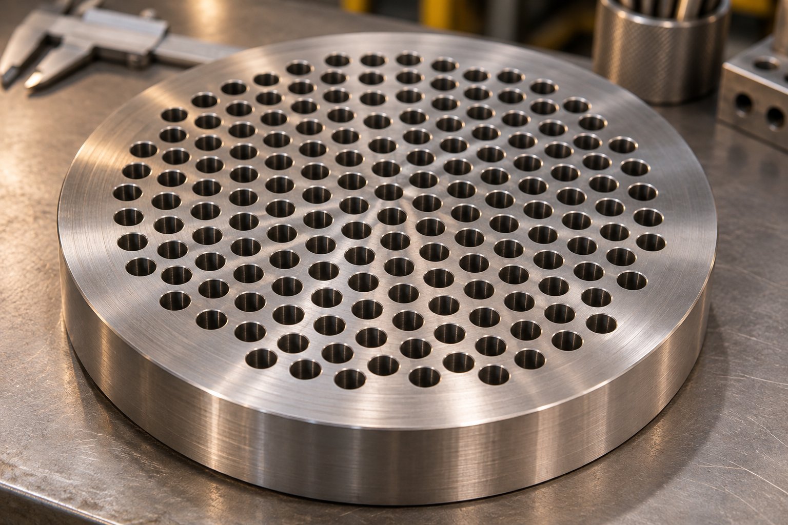
Wrong Extruder Breaker Plate? Spot the Signs Before Scrap Piles Up
Nov 19, 2026
Learn how to select, size, and maintain your extruder breaker plate. Covers hole geometry, pressure drop, polymer-specific specs, and troubleshooting tips.
Read Article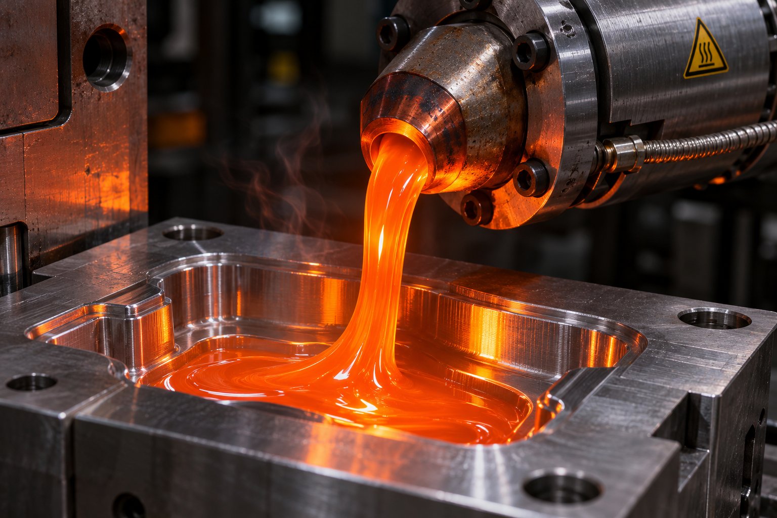
Injection Molding Melt Temperature: Why Your Barrel Settings Lie
Nov 19, 2026
Learn why barrel set points lie about injection molding melt temperature. Complete resin chart, measurement methods, defect troubleshooting, and optimization steps.
Read Article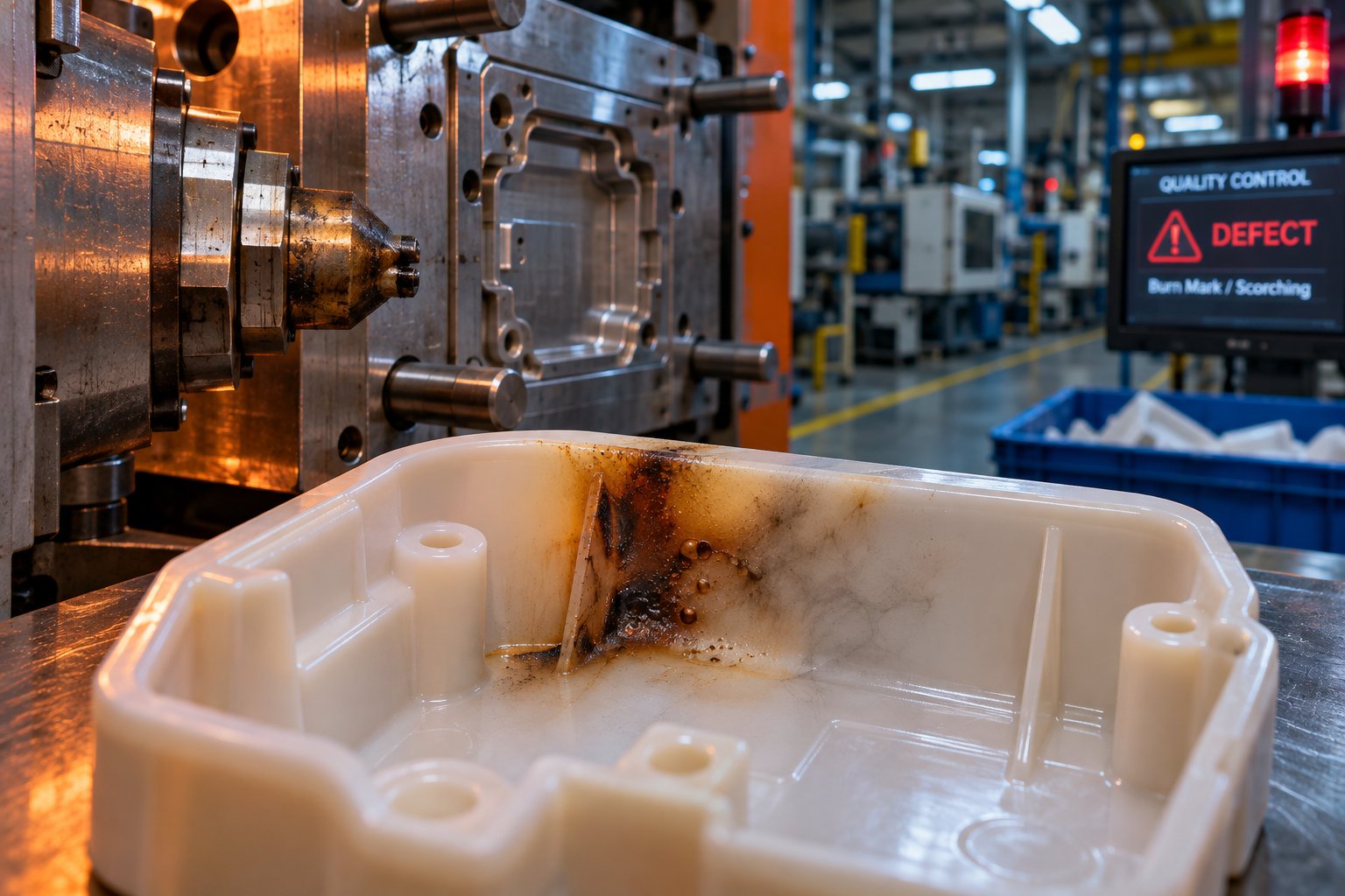
Injection Molding Burn Marks: Diagnose the Root Cause, Kill the Defect
Nov 19, 2026
Learn how to diagnose and fix injection molding burn marks. Covers gas-trap burns, material degradation, moisture defects, mold venting, and screw barrel wear solutions.
Read ArticleLooking for something else?
Search by material, symptom or product and jump straight to the relevant page.
These are navigation suggestions based on keyword matching — not a quotation, not a delivery commitment, and not a substitute for engineering review. Final specification is confirmed by our engineers against your drawings and processed material.
Need help with screw barrel selection?
Share your machine model, processed material and application. Our team can help with pricing and technical support.