

Injection Molding Melt Temperature Explained
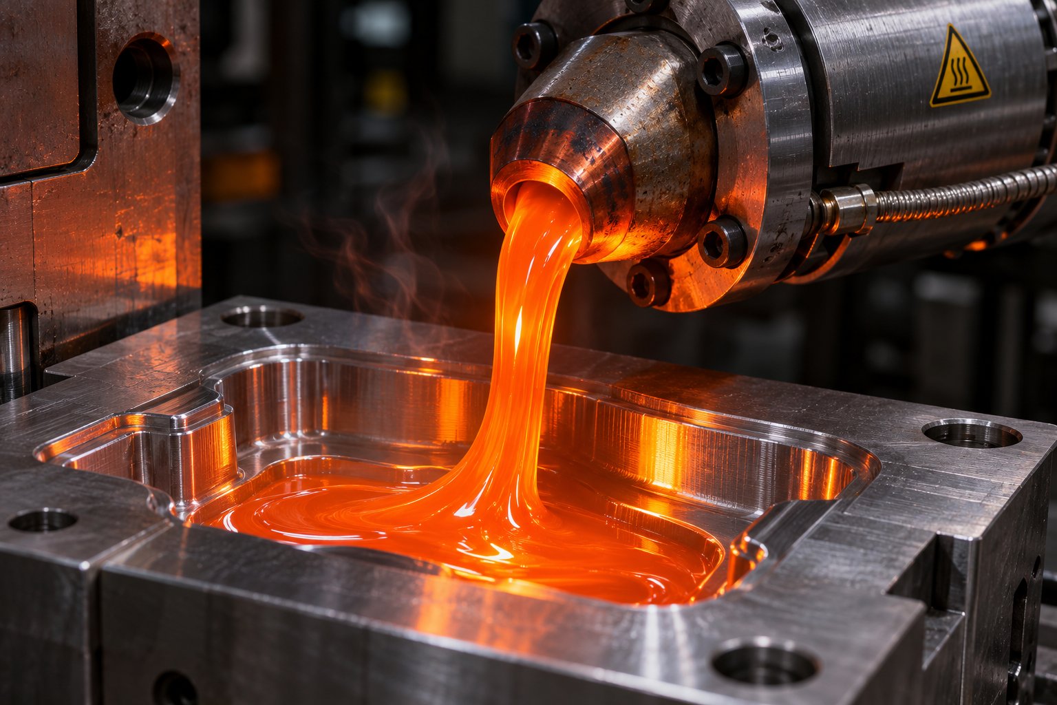
Injection molding melt temperature is the actual temperature of the polymer melt as it exits the machine nozzle and enters the mold cavity. It is not the number displayed on your barrel controller. It is not the set point programmed into your rear, center, or front heating zones. It is the real, measurable thermal state of the plastic material melting temperature at the moment it begins to form your part. That distinction matters more than most molders realize, and ignoring it is one of the most common sources of process instability in the industry.
If you were to walk up to a process engineer and ask, "What temperature is the plastic running at on this machine?" you would likely get one of three answers: a guess based on barrel set points, a reference to the resin supplier's recommended range, or an honest "I'm not sure." As injection molding consultant Umberto Catignani of Orbital Plastics Consulting points out, this is actually a trick thermodynamic question, because barrel thermocouples measure the steel temperature of the barrel wall, not the actual plastic temperature inside. Shear heating from screw rotation, back pressure, residence time, and screw geometry all push the real melt temperature away from whatever number appears on the controller screen.
Melt temperature is not what your controller displays — it is what your polymer actually experiences.
What Melt Temperature Means in Injection Molding
Think of it this way. Your barrel set points are instructions to the heater bands. They tell the machine how hot to make the steel surrounding the polymer. But the polymer itself absorbs energy from two sources: conductive heat from those barrel walls and mechanical shear heat generated by screw rotation. Depending on screw speed, back pressure, and screw design, the actual temperature of the melt can run 10 to 30 degrees Celsius higher — or in some cases even lower — than what the controller displays. At what temp does plastic melt and become a uniform, flowable mass? That depends entirely on what the material truly experiences inside the barrel, not on what you have programmed.
The melting point of plastic varies widely across resin families. Commodity polyolefins like polyethylene soften at relatively low temperatures, while high-performance polymers like PEEK demand extreme heat to reach a processable state. Rubber and elastomeric compounds raise a separate but related question — what temperature does rubber melt or soften enough to flow? Each material brings its own thermal fingerprint, and matching your process to that fingerprint starts with understanding actual melt temperature rather than set-point temperature.
Why Melt Temperature Is the Master Variable
Melt temperature directly controls viscosity, which determines how easily the material flows into the cavity. Because of that single relationship, it influences nearly every outcome in the molding process. Flow behavior, molecular orientation, weld-line strength, crystallization kinetics in semi-crystalline resins, volumetric shrinkage, cycle time, surface finish, and final mechanical properties all trace back to this one variable. Even small changes in melt temperature can lead to noticeable differences in part quality, dimensional stability, and internal stress.
Set it too low, and the material resists filling the cavity — short shots, poor surface gloss, and weak weld lines follow. Set it too high, and you risk thermal degradation, flash, excessive shrinkage, and discoloration. The practical processing window between these extremes can be surprisingly narrow, especially for engineering-grade and high-performance resins.
This guide bridges the gap between quick-reference melt temperature charts and deep process-engineering content. Whether you are a technician dialing in a new mold, a quality engineer troubleshooting dimensional drift, or a process engineer optimizing cycle time, the sections ahead give you both the reference data and the underlying science to make better decisions. The journey starts where all good plastics processing should: with the polymer itself and the thermal behavior baked into its molecular structure.
Amorphous vs Semi-Crystalline Polymers and Melt Behavior
Every resin you load into a hopper carries a molecular blueprint that dictates exactly how much thermal energy it needs — and how it responds when it gets too much or too little. Two plastics sitting side by side on a shelf can look nearly identical as pellets, yet one may soften gently over a wide temperature range while the other resists melting until a sharp threshold is crossed. The difference comes down to molecular architecture: whether the polymer chains are tangled at random or packed into orderly crystalline structures. Understanding that architecture is the first step toward knowing at what temperature does plastic melt for any given resin — and why the answer is never a single number.
Amorphous Polymers and Their Gradual Softening Behavior
Imagine a bowl of cooked spaghetti — strands twisted, overlapped, and entangled with no repeating pattern. That is roughly how molecular chains are arranged in an amorphous polymer. Materials like ABS, polycarbonate (PC), PMMA (sometimes recognized by its trade name as the material behind the melting point of perspex discussions), and general-purpose polystyrene (PS) all share this disordered structure.
Because there are no crystalline regions to "unlock," amorphous resins do not have a true melting point. Instead, they pass through a glass transition temperature (Tg) — a range where the material shifts from a rigid, glassy solid into a softer, rubbery state. Below Tg, molecular motion is restricted and the plastic is stiff. Above it, chains gain mobility, and with enough additional heat the material becomes viscous enough to flow under injection pressure.
What does this mean for processing? You'll notice that amorphous resins tend to be forgiving. Their viscosity drops gradually as temperature rises, giving you a relatively wide window between the point where the material flows well and the point where it starts to degrade. A few degrees above or below your target typically won't cause dramatic swings in fill behavior or part quality. Typical Tg values range from around 100 to 105 degrees Celsius for ABS and PMMA up to approximately 150 degrees Celsius for polycarbonate, with processing temperatures set well above those thresholds to achieve the low viscosity needed for injection.
Semi-Crystalline Polymers and the Crystalline Melting Point
Picture that same spaghetti, but now portions of the strands are neatly folded and stacked into tight, repeating bundles. Those ordered bundles are the crystalline regions found in semi-crystalline polymers such as polypropylene (PP), polyethylene (PE), nylon (PA6 and PA66), acetal (POM), PET, and PEEK.
These crystalline zones act like thermal locks. The material will not flow properly until you supply enough energy to break apart those ordered chain structures — a transition that happens at a distinct crystalline melting point (Tm). Below that point, the polymer may soften slightly in its amorphous regions, but the crystalline domains hold it together. Cross the Tm, and the entire structure releases into a flowable melt relatively quickly.
This sharp transition is exactly why semi-crystalline resins demand tighter control over melt temperature. The gap between "not quite melted" and "beginning to degrade" can be narrow — sometimes only 20 to 40 degrees Celsius for engineering-grade nylons or acetyls. Undershoot and you get unmelted crystalline regions that create weak spots, flow hesitation, and poor surface finish. Overshoot and polymer chains begin to break down through thermal degradation, especially in moisture-sensitive resins like PA66 where what temp melts plastic safely depends on both temperature and moisture content simultaneously.
How Polymer Structure Dictates Your Processing Window
The contrast between these two material classes shows up clearly when you compare their processing behavior side by side.
| Characteristic | Amorphous Polymers | Semi-Crystalline Polymers |
|---|---|---|
| Key Thermal Transition | Glass transition temperature (Tg) — gradual softening | Crystalline melting point (Tm) — sharp solid-to-melt transition |
| Flow Onset | Progressive; viscosity decreases steadily above Tg | Abrupt; material resists flow until Tm is exceeded |
| Typical Processing Window Width | Broader — often 40 to 80 degrees Celsius between minimum fill temperature and onset of degradation | Narrower — often 20 to 50 degrees Celsius between complete melting and degradation |
| Sensitivity to Overheating | Moderate — degradation tends to appear gradually as discoloration or reduced impact strength | Higher — chain scission, hydrolysis (if moisture present), and rapid property loss can occur within a few degrees above the safe limit |
| Common Examples | ABS, PC, PMMA, PS, SAN, PC/ABS blends | PP, PE, PA6, PA66, POM, PBT, PET, PEEK |
Within each category, the practical window narrows or widens further based on two additional factors: melt flow index (MFI) and molecular weight distribution. MFI is an empirical measure of how easily a thermoplastic melt flows under standardized temperature and load conditions. A higher MFI generally indicates shorter polymer chains that flow more readily, which can widen the usable temperature range because the material reaches adequate viscosity at lower temperatures. A lower MFI signals longer chains, higher viscosity, and often a need for higher melt temperatures or more aggressive screw shear to achieve proper flow — which tightens the window on the upper end because you are pushing closer to degradation thresholds.
Molecular weight distribution — how uniform or varied the chain lengths are within a resin batch — adds another layer. A broad distribution means some chains are short and flow easily while others are long and resist motion. This can create inconsistencies in melt behavior that make the effective processing window feel narrower than the datasheet suggests, because conditions that suit the short chains may overheat the long ones, and vice versa.
The takeaway is practical: knowing whether your resin is amorphous or semi-crystalline tells you how forgiving your melt temperature window will be, and understanding MFI and molecular weight distribution tells you how much room you actually have within that window. Both pieces of information are essential before you ever look at a barrel temperature set point — and they set the stage for the specific melt temperature ranges each resin family requires.
Complete Melt Temperature Reference Table by Resin Family
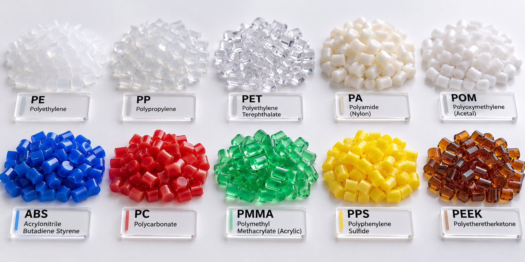
Knowing whether a resin is amorphous or semi-crystalline tells you how it behaves thermally — but it does not tell you the exact temperature range to target. That is where a reliable reference chart earns its place on the shop floor. What temperature does plastic melt at for a given resin? The answer varies dramatically from one polymer family to the next, spanning a range from below 170 degrees Celsius for flexible PVC all the way past 400 degrees Celsius for PEEK. Having every major resin family in a single resource eliminates the need to hunt through a dozen datasheets when you are setting up a new job or troubleshooting a process that has drifted.
The table below lists recommended melt temperature ranges for injection molding — meaning the actual temperature the polymer melt should reach, not merely the crystalline melting point or glass transition of the raw material. It also includes recommended mold temperature ranges and brief processing notes that flag the most common pitfalls for each resin. Bookmark this section; you will come back to it.
Melt Temperature Chart for Commodity and Engineering Resins
| Resin Family | Common Grades | Recommended Melt Range (°C) | Recommended Melt Range (°F) | Mold Temp Range (°C) | Critical Processing Notes |
|---|---|---|---|---|---|
| LDPE | Dow 722, ExxonMobil LD 100 | 160 – 240 | 320 – 464 | 20 – 40 | Very low viscosity at upper range; watch for drool at the nozzle. |
| LLDPE | Dowlex, Exceed | 160 – 240 | 320 – 464 | 20 – 40 | Similar to LDPE; slightly higher melt strength aids thicker parts. |
| HDPE | Marlex, Alathon | 180 – 260 | 356 – 500 | 20 – 60 | High shrinkage (1.5 – 3.0%); adequate packing pressure is essential. |
| PP (Homo & Copolymer) | Pro-fax, Moplen | 200 – 280 | 392 – 536 | 20 – 80 | The polypropylene melting temp (Tm) is ~160 – 165 °C, but processing requires significantly higher barrel settings for proper flow. |
| PS (GPPS) | Styron, Total GPPS | 180 – 260 | 356 – 500 | 20 – 50 | Amorphous; easy flow. Degrades quickly above 280 °C — yellowing and off-gassing. |
| PS (HIPS) | Styron A-Tech, Total HIPS | 190 – 260 | 374 – 500 | 20 – 60 | Rubber phase can degrade at excessive temperatures; monitor for loss of impact strength. |
| ABS | Cycolac, Terluran | 200 – 260 | 392 – 500 | 40 – 80 | Sensitive to moisture; dry 2 – 4 hours at 80 °C. Yellows readily above 270 °C. |
| SAN | Luran, Tyril | 200 – 260 | 392 – 500 | 40 – 80 | Higher stiffness than ABS; similar drying and thermal limits. |
| PC | Makrolon, Lexan | 280 – 320 | 536 – 608 | 80 – 120 | High melt viscosity; requires thorough drying (120 °C for 3 – 4 hours). Hydrolyzes if wet. |
| PC/ABS Blends | Bayblend, Cycoloy | 240 – 280 | 464 – 536 | 60 – 90 | Combines PC toughness with ABS flow; moisture control remains critical. |
| PMMA (Acrylic) | Plexiglas, Altuglas | 220 – 260 | 428 – 500 | 40 – 80 | Dry at 80 °C for 3 – 4 hours. Excellent optical clarity when processed within range. The plastic melting point discussions around perspex and acrylic refer to this family. |
| POM (Acetal) | Delrin (Homo), Celcon (Copoly) | 190 – 220 | 374 – 428 | 60 – 120 | Narrow window; formaldehyde off-gassing above 230 °C. Copolymer grades offer better thermal stability than homopolymer. |
| PA6 (Nylon 6) | Ultramid B, Akulon | 230 – 260 | 446 – 500 | 60 – 90 | Strict drying required (80 °C, 4 – 6 hours, <0.2% moisture). Hydrolysis above 240 °C if wet. |
| PA66 (Nylon 66) | Zytel, Ultramid A | 260 – 295 | 500 – 563 | 60 – 100 | Even more moisture-sensitive than PA6; rapid hydrolytic degradation above 260 °C if moisture exceeds 0.2%. |
| PBT | Valox, Ultradur | 240 – 270 | 464 – 518 | 60 – 90 | Semi-crystalline polyester; dry at 120 °C for 3 – 4 hours. Fast crystallization allows short cycles. |
| PET | Rynite, Arnite | 260 – 290 | 500 – 554 | 80 – 130 | Requires aggressive drying (150 °C, 4 – 6 hours). Higher mold temperatures promote crystallinity and dimensional stability. |
| TPU | Elastollan, Pellethane | 190 – 230 | 374 – 446 | 20 – 50 | Moisture-sensitive; dry at 80 – 100 °C for 2 – 4 hours. Shear-sensitive — avoid excessive screw RPM. |
| TPE (Styrenic, Olefinic) | Santoprene, Kraton | 170 – 240 | 338 – 464 | 20 – 50 | Wide family with varied ranges; always check the specific grade datasheet. Low injection pressures typical. |
| PVC (Rigid) | Geon, Vinnolit | 170 – 200 | 338 – 392 | 30 – 60 | PVC melting temperature must be carefully controlled — degrades rapidly above 210 °C, releasing HCl gas. Stabilizer package matters. |
| PVC (Flexible) | Plasticized grades | 160 – 190 | 320 – 374 | 20 – 50 | Plasticizer content lowers required processing temperature; excessive heat drives off plasticizer and causes brittleness. |
| PPS | Ryton, Fortron | 290 – 330 | 554 – 626 | 120 – 160 | Semi-crystalline; high mold temperature critical for crystallinity and dimensional stability. Minimal moisture sensitivity. |
| PEI (Ultem) | Ultem 1000, Ultem 2300 | 340 – 400 | 644 – 752 | 120 – 165 | Amorphous; hygroscopic. Dry at 150 °C for 4 – 6 hours. Excellent flame retardancy (UL 94 V-0). |
| PEEK | Victrex 450G, Solvay KetaSpire | 360 – 400 | 680 – 752 | 160 – 200 | Highest-performance semi-crystalline resin on this list. Demands specialized high-temperature barrels. Slow crystallization at low mold temps reduces part performance. |
| PPO/PPE (Modified) | Noryl | 260 – 300 | 500 – 572 | 60 – 100 | Usually blended with PS for processability. Low moisture absorption; good dimensional stability. |
| LCP | Vectra, Zenite | 280 – 330 | 536 – 626 | 80 – 120 | Exceptional flow for ultra-thin walls (<1 mm). Rapid solidification; gate design is critical to avoid short shots. |
A few patterns jump out immediately. Commodity resins like PE, PP, and PS cluster toward the lower end of the temperature spectrum and generally tolerate wider processing bands. Engineering resins — nylons, polycarbonate, PBT, PET — push into the mid-range and introduce moisture sensitivity as a major complication. High-performance materials like PPS, PEI, PEEK, and LCP demand barrel temperatures that exceed the capabilities of standard machines and require specialized hardware, precise drying protocols, and elevated mold temperatures to achieve proper crystallization and mechanical performance.
Filled and Reinforced Materials — How Fillers Shift the Processing Window
Adding glass fibers, mineral fillers, or carbon-fiber reinforcement to a base resin changes more than mechanical properties — it shifts the thermal processing window as well. Fillers increase melt viscosity because rigid particles and fiber bundles resist flow. To compensate, you typically need to raise melt temperature by 10 to 20 degrees Celsius (and sometimes mold temperature by a similar margin) compared to the unfilled base resin. Higher filler loading percentages push that offset even further.
| Reinforced Resin | Typical Filler Content | Melt Temp Offset vs. Unfilled Base | Mold Temp Offset vs. Unfilled Base | Key Consideration |
|---|---|---|---|---|
| Glass-Filled PA6 / PA66 | 15 – 50% GF | +10 to +20 °C | +10 to +20 °C | Abrasive to barrel and screw; hardened components recommended. Minimize back pressure to preserve fiber length. |
| Glass-Filled PC | 10 – 30% GF | +10 to +15 °C | +10 to +15 °C | Already high-viscosity base resin; filler makes flow even more demanding. Larger gates preferred. |
| Mineral-Filled PP | 20 – 40% Talc or CaCO3 | +5 to +15 °C | +5 to +10 °C | Less abrasive than glass; improves stiffness and reduces shrinkage with moderate viscosity increase. |
| Carbon-Fiber-Filled Resins (PA, PEEK, PPS) | 10 – 30% CF | +10 to +20 °C | +10 to +20 °C | Extremely abrasive; requires wear-resistant barrel liners, hardened screws, and careful screw-speed management. |
Imagine running 30% glass-filled PA66 at the same barrel profile you use for unfilled nylon. The increased viscosity means the material struggles to fill the cavity, weld lines weaken, and surface finish suffers — all symptoms that look like the melt temperature is too low, because it effectively is for that formulation. Bumping the melt temperature up by 10 to 20 degrees and raising the mold temperature to match restores proper flow and fiber wetting, producing parts that actually deliver the strength the filler was added to provide.
Why Resin Datasheets Are Your Final Authority
The ranges in these tables represent broadly accepted industry values gathered from resin supplier recommendations and processing guides. They are starting points — not final answers. Every resin manufacturer publishes a technical datasheet (TDS) for each specific grade, and those documents account for the exact molecular weight, additive package, filler type, and stabilizer system in that formulation. A general-purpose PP homopolymer and a high-impact PP copolymer may both fall under the "PP" family, yet their ideal melt temperatures can differ by 20 degrees or more.
Always verify the recommended melt range, mold temperature, maximum residence time, and drying requirements on the TDS for the exact grade you are running. Treat the chart above as the map that gets you to the right neighborhood — then let the manufacturer's datasheet guide you to the precise address. The numbers on your barrel controller, of course, are an entirely different story — and the gap between those set points and the actual temperature your polymer experiences is the subject worth examining next.
Set Temperature vs Actual Melt Temperature
Here is a scenario that plays out in molding facilities every day. Every zone on the controller reads exactly where it should. The nozzle set point matches the resin supplier's recommendation. Everything looks right on the screen — and yet the parts coming off the press tell a different story. Flash one cycle, short shots the next, dimensional drift that no amount of set-point tweaking seems to fix. What is going on?
The answer is deceptively simple: the plastic melting temperature your controller displays is the temperature of the barrel steel, not the temperature of the polymer flowing inside it. These two numbers can diverge significantly, and the gap between them is where most unexplained process instability lives. Understanding why they differ — and learning how to measure the real value — is arguably the single most practical skill a molder can develop.
Why Barrel Set Points Lie About Your Melt Temperature
Barrel thermocouples are embedded in the barrel wall. They measure steel temperature at a fixed point on the outer surface or within the barrel body. They do not — and physically cannot — measure the temperature of the molten polymer flowing through the screw channel inside. As Orbital Plastics Consulting emphasizes, the thermocouples are measuring the steel temperature of the barrel and nozzle, not the actual plastic temperature inside, which is precisely why reviewing barrel set points alone will never reveal the true melting point plastic reaches during processing.
Three physical phenomena drive the discrepancy:
- Thermocouple placement: The sensor reads barrel-wall temperature, which lags behind or runs ahead of the melt-core temperature depending on heat flow direction. When heater bands cycle off and shear continues generating heat inside, the melt can be hotter than the barrel wall. When the machine sits idle between cycles, the melt cools from the outside in while the barrel wall retains heat — making the controller reading optimistically high.
- Shear heating: As the screw rotates during recovery, mechanical friction between screw flights, polymer chains, and the barrel bore converts rotational energy into thermal energy. This viscous dissipation adds heat directly to the polymer — energy that heater bands never supplied and barrel thermocouples never see. Depending on screw speed, back pressure, and resin viscosity, shear heating can contribute a substantial share of total melt energy, sometimes exceeding what the heater bands provide.
- Residence time: The length of time material spends inside the heated barrel determines how close it comes to thermal equilibrium with the barrel wall. Short residence times mean the melt may not absorb enough conductive energy from the barrel to reach the set-point temperature — so the actual melt runs cooler than the display suggests. Excessively long residence times, on the other hand, allow the material to soak up more energy and can push it past the target, especially in the presence of continuous shear.
The net result? Actual melt temperature commonly runs 10 to 30 degrees Celsius higher than the rear-zone set point. Even at the nozzle — the zone closest to the melt exit — the real polymer temperature can differ from the set point by 5 to 15 degrees Celsius depending on screw speed and back pressure. Research by Johnston and Kazmer at the University of Massachusetts Lowell confirmed that melt temperature in the nozzle can be as much as 44 degrees Celsius above the barrel temperature due to viscous dissipation and adiabatic compression during injection. Their intrusive thermocouple data showed a sharp temperature spike during the injection phase that no barrel-zone display would ever reveal.
Two machines sitting side by side running identical barrel profiles can produce melts that differ by 20 to 40 degrees Fahrenheit simply because their screws, compression ratios, and wear states are different. The barrel set point is an instruction to a heater. It is not a measurement of what temperature will plastic melt at inside your specific machine.
A Step-by-Step Method for Measuring Actual Melt Temperature
If the controller cannot tell you what the polymer is actually experiencing, how do you find out? The answer is hands-on measurement — an air-shot procedure that every molder should perform during setup, after process changes, and periodically during production runs. The procedure is straightforward:
- Purge into free air. Retract the injection unit from the mold (or use an air-shot fixture if available). Run a normal cycle so the machine injects a full shot of material into the open air. This produces a "purge patty" — a mass of molten polymer at the temperature it would normally enter the mold cavity.
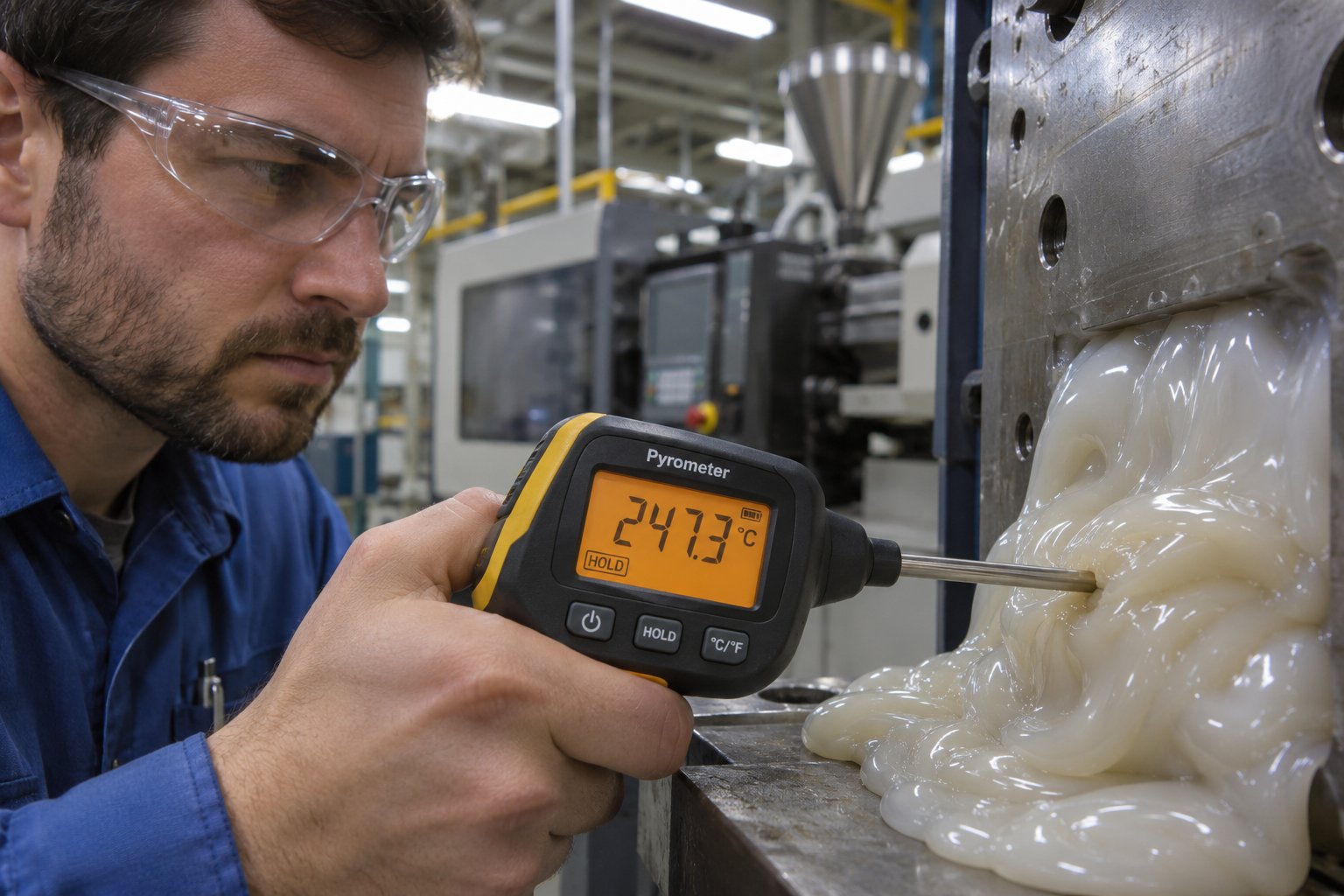
- Insert a probe immediately. Within seconds of the purge, push a handheld pyrometer needle or thermocouple probe directly into the center of the molten mass. The center measurement is critical because the surface cools rapidly on contact with air, and a surface reading will understate the true melt temperature.
- Record the peak reading. Wait for the temperature display on the probe to stabilize or peak, then log the value. Compare it to the nozzle set point and to each barrel zone set point.
- Calculate the delta. If the measured melting temp of plastic is 12 degrees Celsius above the nozzle set point, that delta tells you how much shear and residence-time effects are adding to the conductive heat from the barrel. Use this information to adjust zone temperatures — typically by lowering set points if the melt is running hotter than your target range, or investigating screw speed and back pressure if the melt is cooler than expected.
A few practical cautions apply. The handheld probe measurement itself has limitations — the melt begins cooling the instant it exits the nozzle, and the probe's thermal mass can influence the reading. Calibrate your pyrometer regularly, and use the same procedure and probe each time to maintain consistency even if absolute accuracy has a margin of error. Infrared cameras offer a non-contact alternative but require correct emissivity settings for the polymer being measured, which introduces its own uncertainty. Despite these limitations, even an imperfect direct measurement gives you far more useful information than the barrel controller alone.
If you have never measured your actual melt temperature with a probe, you are processing blind.
Shot-to-Shot Consistency and What Causes Variation
Measuring actual melt temperature once during setup is valuable. But the real challenge is keeping that temperature consistent across hundreds or thousands of consecutive shots. Shot-to-shot variation in melt temperature — even swings as small as 3 to 5 degrees Celsius — translates directly into dimensional instability, weight fluctuation, and cosmetic defects like gloss variation or flow-line visibility.
What drives these cycle-to-cycle swings? Several mechanical and process factors work together:
- Inconsistent screw recovery time: If the screw takes slightly longer to recover on some cycles than others — due to pellet bridging in the hopper, inconsistent feed-throat cooling, or slight variations in regrind particle size — the material spends a different amount of time being sheared and heated. That changes the plastic melting temperature from shot to shot.
- Check-valve (non-return valve) wear: A worn check ring allows molten material to leak backward over the screw flights during injection. This backflow reprocesses already-sheared polymer, adding extra thermal history and raising the temperature of the re-mixed melt unpredictably. It also reduces shot-volume consistency, compounding the dimensional problems.
- Fluctuating back pressure: Hydraulic systems on older machines may not hold back pressure at a perfectly stable value. Even small fluctuations change the intensity of shear during recovery, directly modulating how much mechanical energy converts to heat in the melt.
- Heater-band cycling: Heater bands maintain temperature by switching on and off under PID control. Bands with poor barrel contact, corroded surfaces, or failing relays cycle erratically, creating thermal ripples in the barrel wall that the melt absorbs unevenly. A band can display a perfect set-point number while its actual heat output oscillates enough to shift melt temperature by several degrees.
- Residence-time shifts: Any change to cycle time — an operator pausing the machine, a robot delay, an extended cooling hold — alters how long the next shot sits in the heated barrel. Longer dwell means more thermal soak and potentially higher melt temperature; shorter dwell means less equilibration and cooler melt. As Johnston and Kazmer's nozzle probe data demonstrated, the temperature of cooler melt residing in the nozzle gets flushed and replaced by hotter melt from the barrel during each injection stroke, and the magnitude of that temperature swing depends on how long the melt has been sitting between cycles.
The cumulative effect of these factors is a process that looks stable on the controller screen but produces parts with measurable variation. Constant machine settings do not equal constant part properties — a principle that experienced process engineers understand intuitively but that can frustrate anyone who believes the numbers on the display tell the whole story.
Controlling melt temperature consistency requires looking beyond the barrel heaters. Screw speed, back pressure, screw geometry, and the physical condition of the plasticating hardware all contribute energy to the melt independently of what the heater bands deliver — and those mechanical factors deserve their own careful examination.
Mechanical Factors That Drive Actual Melt Temperature
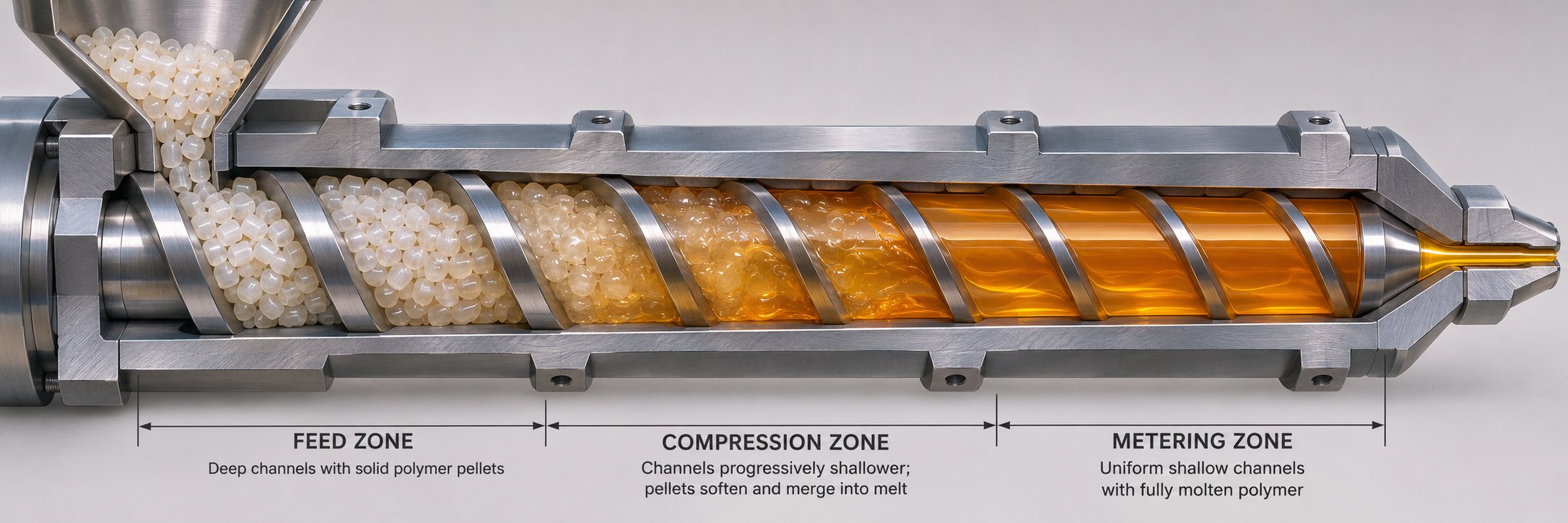
Heater bands get most of the attention when molders think about plastic melting temp, but they are only part of the equation — and often not even the dominant part. Inside the barrel, a rotating screw is doing mechanical work on the polymer with every revolution. That work converts into heat through viscous friction, and the amount of heat generated depends on a set of mechanical and process variables that operate entirely outside the heater-band control loop. Change screw speed by 20 RPM, bump back pressure up by a few bar, or swap a worn screw for a new one, and you can shift the actual melt temperature by 10 to 20 degrees Celsius without touching a single zone set point.
Think of it as a thermal budget. Part of the budget comes from conductive heating through the barrel wall. The rest comes from shear energy — mechanical friction between the screw flights, the polymer melt, and the barrel bore. On some machines processing high-viscosity engineering resins at aggressive screw speeds, shear heating can contribute more thermal energy than the heater bands. Understanding and controlling each contributor is what separates a stable, repeatable process from one that drifts unpredictably.
Screw Speed and Back Pressure Effects on Shear Heating
Every time the screw rotates during recovery, it drags molten polymer forward through the narrowing channels between flights and barrel wall. The faster the screw turns, the higher the shear rate imposed on the melt — and the more kinetic energy converts to heat through viscous dissipation. As Orbital Plastics Consulting notes, increasing screw rotation speed and back pressure generates larger amounts of shear heat, directly raising the actual polymer temperature beyond what barrel heaters deliver.
Imagine running a polycarbonate job at 80 RPM versus 120 RPM with everything else held constant. The polycarbonate melting point — the threshold at which the amorphous chains become fully mobile — does not change. But the temperature the polymer actually reaches inside the barrel does. That 40 RPM increase can easily add 10 to 20 degrees Celsius to the melt, pushing you from the middle of the processing window toward the upper boundary where thermal degradation and yellowing begin. For a high-viscosity resin like PC, where what is the melting point of plastic versus the safe processing ceiling may be only 30 to 40 degrees apart, that kind of unintended temperature boost matters enormously.
Back pressure operates through a similar mechanism but adds a time dimension. When you increase back pressure, you force the screw to work harder during recovery — it has to push against greater resistance as it retracts. This extends the shearing phase, keeping the polymer under active mechanical work for a longer period during each recovery stroke. The result is a more homogeneous melt with better color mixing and additive distribution, which is why process engineers routinely use moderate back pressure to improve melt quality. But every additional bar of resistance also adds thermal energy. Push back pressure too high and you overshoot your target temperature, degrade the polymer, and introduce the very defects — splay, discoloration, brittleness — that you were trying to prevent.
The interaction between screw speed and back pressure is compounding rather than additive. Raising both simultaneously does not just double the shear input — it can amplify it, because higher screw RPM increases the rate of shearing while higher back pressure increases the duration. This is why experienced molders adjust these two parameters incrementally and always verify the actual melt temperature after each change, rather than assuming the controller's zone readings still apply.
How Screw Geometry Shapes Melt Temperature
Screw speed and back pressure are process settings you can change with a few keystrokes. Screw geometry, by contrast, is baked into the hardware sitting inside your barrel — and it has an equally powerful effect on how much shear energy reaches the polymer. Four geometric characteristics matter most:
- Compression ratio: This is the ratio of flight depth in the feed zone to flight depth in the metering zone. A general-purpose screw for thermoplastics typically falls between 2.0:1 and 3.5:1, though the range extends from 1.5:1 to 4.5:1 for specialized applications. A higher compression ratio forces the polymer through a progressively tighter channel, generating more shear heating per unit of output. A 4:1 ratio puts roughly twice as much mechanical energy into the melt as a 2:1 ratio — a substantial difference that directly elevates the plastic melting temp independent of barrel heater settings. Nylon screws, for example, commonly start at a 4:1 ratio because the semi-crystalline structure demands aggressive energy input to break apart crystalline domains, while polyethylene screws typically start around 3:1.
- L/D ratio (length-to-diameter): This describes the flighted length of the screw relative to its diameter. Standard general-purpose screws run a 20:1 L/D, but ratios can range from 16:1 to 25:1 for thermoplastics. A longer screw means more residence time in the heated barrel and more cumulative rotations of material through the shear zone. A 25:1 L/D screw — common in thin-wall packaging and PET preform applications — delivers substantially more shear energy than a 16:1 screw at the same RPM, raising actual melt temperature without any change to zone set points.
- Flight depth: Shallower flights in the metering section force the melt through a thinner channel at higher shear rates. Deeper flights reduce shear intensity but increase throughput per revolution. The interplay between feed-section depth and metering-section depth is what defines the compression ratio, but the absolute depth in the metering zone also determines the shear rate the polymer experiences in the final stage before injection.
- Barrier flights and mixing sections: Barrier screws separate the solid bed from the melt pool using a secondary flight, improving melting efficiency. Dynamic or dispersive mixing sections add localized high-shear zones that break up unmelted particles and improve homogeneity — but they also inject additional thermal energy into the polymer at those points. A screw equipped with a Maddock mixer or a pineapple mixing head can raise the melt temperature several degrees beyond what the same base screw geometry would produce without the mixer.
Here is the practical problem: most molding facilities do not know the compression ratio or detailed geometry of the screws installed in their machines. As Umberto Catignani of Orbital Plastics Consulting observes, he has rarely seen compression ratio noted on machine press specifications, and most molders are unaware whether they are running a general-purpose screw, a barrier design, or a screw with a dynamic mixing section. That knowledge gap creates a blind spot in understanding why the actual melt temperature deviates from set points — and it can lead to persistent issues like degraded material, color inconsistencies, and dimensional variation that resist all the usual process adjustments.
Barrel and Screw Wear as Hidden Sources of Temperature Deviation
Screw geometry effects are at least constant — the compression ratio does not change from shot to shot. Wear, on the other hand, is a slow-moving variable that shifts your thermal baseline gradually over weeks and months, making it one of the most insidious causes of melt-temperature drift. Because the deterioration is incremental, processors often compensate unconsciously — raising barrel temperatures a few degrees here, adding back pressure there — masking the underlying hardware problem without actually solving it.
When the screw flight outer diameter wears down, the clearance between the flight tip and the barrel bore increases. That widening gap allows molten polymer to flow backward over the flights — a phenomenon called leakage flow. Material that leaks backward gets sheared again as the screw continues to rotate, adding extra thermal history. The result is localized overheating of the re-processed material, which can cause degradation, black specks, and color streaks. Meanwhile, the forward-conveying efficiency of the screw drops, meaning recovery time increases and the overall throughput per revolution decreases.
Barrel bore wear creates the same clearance problem from the other side. A worn barrel allows more material to slip past the flights, reducing the screw's ability to build pressure and push the melt forward efficiently. In severe cases, the molder sees unstable cushion positions, fluctuating shot weights, and a thermolator injection molding cooling system that cannot compensate for the thermal inconsistency because the problem is upstream in the plasticating unit, not in the mold's thermal management.
Worn check rings (non-return valves) compound the issue during injection. A check ring that does not seal properly lets melt flow backward over the screw during the injection stroke, reprocessing material that has already been brought to temperature. This backflow adds unpredictable thermal energy to the melt on subsequent shots and introduces shot-to-shot temperature variation that no amount of PID tuning on the barrel heaters can correct.
The practical signs of wear-driven temperature deviation include:
- Gradual increase in screw recovery time over months of production
- Need to progressively raise barrel set points or back pressure to maintain the same measured melt temperature
- Black specks or degraded material despite correct purging procedures
- Unstable cushion position and shot-weight variation
- Color mixing inconsistencies or visible streaking
When these symptoms appear and standard process adjustments — zone profiles, screw speed, back pressure — fail to restore stability, the screw and barrel themselves become the last link in the diagnostic chain. Measuring the screw flight OD at multiple points along its length and comparing it to the barrel bore diameter reveals whether the radial clearance has grown beyond acceptable limits. A visual inspection alone is not enough; caliper and bore-gauge measurements against the original specification are necessary to quantify the wear.
If the measurements confirm excessive clearance or geometry mismatch, the logical step is replacing or upgrading the plasticizing unit with components designed for the specific resin, machine, and shot requirements. This is where a tailored engineering review adds value — assessing screw geometry, wear patterns, melting behavior, mixing performance, and material-retention concerns to match the replacement hardware to the application. NANHAIYA's custom injection molding screw barrels, for example, are manufactured around the specific machine specifications, resin characteristics, and shot requirements of each application, with a technical review process that evaluates all of these factors before manufacturing begins. That level of application-specific matching is what restores the thermal precision that wear has gradually stolen.
Given the number of variables at play, the question becomes: in what order should you investigate and adjust when actual melt temperature is off target? A systematic sequence prevents chasing symptoms and isolates the root cause efficiently.
- Start with screw RPM. Reduce screw speed if the measured melt temperature exceeds the target; increase it if the melt is running cool. RPM adjustments produce immediate, measurable changes in shear heat input and are the fastest lever to pull.
- Adjust back pressure. Lower back pressure to reduce shear duration and cool the melt, or raise it modestly to improve homogeneity and add thermal energy. Always re-measure actual melt temperature after each back-pressure change — the effect can be larger than expected.
- Modify the barrel zone-temperature profile. If RPM and back pressure adjustments alone cannot reach the target melt temperature, adjust zone set points. Raise or lower the front zone first, since this is where the next shot resides and where conductive heat transfer has the most immediate impact on the melt exiting the nozzle.
- Evaluate screw and barrel condition. If the target melt temperature still cannot be achieved or held consistently after optimizing screw speed, back pressure, and zone profiles, inspect the plasticizing hardware. Measure screw flight diameters, barrel bore dimensions, and check-ring sealing performance. Worn or mismatched components are the root cause when process adjustments run out of room.
Following this sequence saves time, avoids masking hardware problems with process band-aids, and ensures that each variable is isolated before moving to the next. It also reveals an important truth: the mechanical state of your plasticizing unit sets the boundaries of what your process adjustments can achieve. No amount of zone-temperature tweaking can compensate for a screw that has lost its compression geometry or a barrel bore that has worn beyond tolerance.
Mechanical factors determine how much energy reaches the polymer — but they are not the only upstream influence on melt quality. Before the resin ever touches the screw, its moisture content and thermal history during drying have already set the stage for how it will respond to heat inside the barrel. For hygroscopic materials, that preparation step can make or break the entire process.
Material Drying and Mold Temperature Interactions
You can dial in the perfect barrel profile, verify actual melt temperature with a probe, and confirm that your screw geometry matches the resin — and still produce parts riddled with splay, brittleness, and mechanical failure. The culprit is not a process setting. It is something that happened — or did not happen — before the material ever reached the feed throat. Moisture hiding inside polymer pellets reacts violently at processing temperatures, and the damage it causes cannot be reversed by adjusting anything on the controller. For hygroscopic resins, drying is not a preliminary step. It is a critical process variable with as much influence on part quality as the injection molding melt temperature itself.
Why Moisture Destroys Polymers at Melt Temperature
Many molders assume that moisture simply evaporates when the resin hits the heated barrel — that the water boils off harmlessly and the polymer continues on its way. That assumption is wrong, and it is responsible for an enormous amount of scrap, rework, and misdiagnosed process issues across the industry.
Hygroscopic polymers — materials like nylon (PA6, PA66), PC plastic, PET, PBT, TPU, and PMMA — absorb water into their molecular structure, not just onto the pellet surface. When these resins enter the barrel without adequate drying, the absorbed water follows the polymer into the melt phase. At temperatures above approximately 240 degrees Celsius, something far more destructive than evaporation occurs: hydrolytic degradation. Water molecules chemically attack the polymer backbone, splitting long chains into shorter segments in a reaction that directly reduces molecular weight.
That reduction in molecular weight lowers the material's strength, impact resistance, and elongation at break — permanently. The vaporized moisture also forms gas pockets within the melt, which emerge as visible splay (silvery streaks), surface bubbles, and internal voids. Color shifts, yellowing, and haze are additional symptoms, particularly in transparent or light-colored parts where even minor degradation becomes magnified. As Precision Color Compounds highlights, trapped moisture in PET or nylon can cause visible yellowing or darkening even when the initial color match was perfect — because hydrolysis alters the polymer itself, not just the surface.
The critical point to understand: once hydrolytic chain scission occurs, no downstream process adjustment can undo the damage. Lowering the barrel temperature will not reconnect broken chains. Increasing pack pressure will not restore lost impact strength. The degradation is irreversible and baked into the part at the molecular level.
Drying Requirements for Hygroscopic Resins
Preventing hydrolytic degradation requires bringing moisture content below a critical threshold before the material enters the barrel. Each resin family has a defined maximum moisture level — typically between 0.02% and 0.10% by weight — along with specific drying temperatures and minimum drying times needed to reach that target.
| Resin | Max Moisture Content | Drying Temperature (°C / °F) | Minimum Drying Time (Hours) | Key Drying Notes |
|---|---|---|---|---|
| PA6 (Nylon 6) | 0.10 – 0.20% | 80 °C / 176 °F | 4 – 6 | Absorbs moisture rapidly; seal containers immediately after drying. ABS plastic melt temperature range is lower, but nylon's hydrolysis risk is far greater. |
| PA66 (Nylon 66) | 0.10 – 0.20% | 80 – 90 °C / 176 – 194 °F | 3 – 6 | Degrades aggressively above 260 °C when wet. Even 0.25% moisture can trigger visible splay and chain breakdown. |
| PC (Polycarbonate) | 0.02% | 120 °C / 250 °F | 3 – 4 | Extremely low moisture threshold. Microbubbles, haze, and warping result from even slight over-moisture. PC plastic demands some of the tightest drying discipline. |
| PET | 0.02% | 150 – 165 °C / 302 – 325 °F | 4 – 6 | Cloudiness, yellowing, and brittleness at what temp does plastic melt if wet. Crystallizing dryers recommended for amorphous PET pellets. |
| PBT | 0.02 – 0.04% | 120 °C / 250 °F | 3 – 4 | Splay, gloss loss, and color shift are common moisture-related defects. |
| TPU | 0.02 – 0.05% | 80 – 100 °C / 176 – 212 °F | 2 – 4 | Shear-sensitive; combining undried material with high screw RPM compounds degradation. |
| PMMA (Acrylic) | 0.04 – 0.06% | 80 °C / 176 °F | 3 – 4 | Moisture-driven bubbles are especially damaging in optical and transparent applications. |
| ABS | 0.05 – 0.10% | 80 °C / 176 °F | 2 – 3 | Lower risk than PC or nylon, but minor streaking and surface dullness still occur above threshold. |
| PEI (Ultem) | 0.02% | 150 °C / 302 °F | 4 – 6 | High-performance amorphous resin processed at 340 – 400 °C; moisture at these temperatures causes severe degradation. |
A few practical details deserve emphasis. First, drying time starts counting only after the dryer bed reaches the target temperature — not from the moment you turn the dryer on. A hopper dryer loaded with cold, wet pellets may take 30 to 60 minutes just to heat through before effective drying begins. Second, desiccant dryers must maintain a dew point of -40 degrees Celsius or lower to pull moisture out of hygroscopic polymers efficiently. A dryer running with a saturated desiccant bed will circulate warm air without removing meaningful moisture, giving a false sense of protection. Third, material that has been properly dried can reabsorb moisture from ambient air surprisingly fast — polycarbonate, for instance, can exceed its 0.02% threshold within 15 to 30 minutes of sitting in an open hopper in a humid environment. Sealed handling systems and covered hoppers are not optional for moisture-sensitive resins.
Perhaps the most costly mistake is misdiagnosing moisture damage as a melt-temperature problem. Imagine a technician seeing splay on parts molded from PA66. The instinct is to lower the barrel temperature, since splay often resembles a symptom of overheating. But if the root cause is moisture-driven hydrolysis rather than excessive thermal energy, reducing the barrel set points pushes the actual melt temperature below the optimal range. The splay may diminish slightly — because lower temperatures reduce the rate of the hydrolytic reaction — but new defects appear in its place: short shots from increased viscosity, poor surface finish, weak weld lines, and incomplete crystallization. The technician chases one problem into another, never addressing the real issue: the dryer was not doing its job.
Melt and Mold Temperature as an Integrated Thermal System
Melt temperature and mold temperature are not independent settings. They form two halves of a single thermal system that governs how the polymer fills the cavity, how quickly the skin layer solidifies against the mold wall, and how the material crystallizes (or relaxes, in amorphous resins) during cooling. Adjusting one without considering the other leads to imbalances that show up as warpage, residual stress, poor crystallinity, and dimensional instability.
Higher mold temperatures slow the formation of the frozen skin layer on the cavity wall. This keeps the flow channel open longer, allowing material to travel farther before the advancing melt front freezes off. In practice, this means a moderately higher mold temperature can compensate for a marginally lower melt temperature by maintaining effective flow length — a useful technique when you need to keep the polymer within a tight thermal window to avoid degradation but still need to fill a long or complex cavity. Mold temperatures also directly influence surface replication: a warmer mold allows the polymer to conform more closely to the mold surface texture before solidifying, improving gloss and detail reproduction.
For semi-crystalline resins, mold temperature plays an even more critical role. The rate at which the polymer cools through its crystallization range determines the degree of crystallinity — and with it, the part's stiffness, chemical resistance, and dimensional stability. A cold mold quenches the material too quickly, trapping polymer chains in a largely amorphous state and producing parts that are dimensionally unstable and mechanically weaker than the resin's potential allows. PPS, PET, and PEEK all require elevated mold temperatures — often above 120 degrees Celsius — specifically to promote adequate crystallization.
The opposite imbalance is equally problematic. Running a high melt temperature against an excessively cold mold creates a steep thermal gradient from the core of the part to the surface. Research on warpage in injection molding has demonstrated that melt temperature and mold temperature interact significantly: at higher mold temperatures, increasing the melt temperature produces a greater increase in warpage than the same melt temperature increase at lower mold temperatures. That steep gradient between a hot melt core and a cold mold surface locks in differential shrinkage — the outer skin solidifies and contracts while the core remains molten and shrinks later — resulting in residual stress, warpage, and in semi-crystalline parts, uneven crystallization that creates regions of differing mechanical properties within the same part.
The practical rule is straightforward: treat melt and mold temperatures as a pair, not as isolated inputs. When you raise one, evaluate whether the other needs to follow. When troubleshooting defects like warpage, sink marks, or poor dimensional control, look at the temperature differential between the two — not just the absolute value of either one. A well-balanced thermal system minimizes internal stress, promotes uniform shrinkage, and gives the polymer the best chance to deliver the properties its datasheet promises.
With material preparation and the mold's thermal environment properly accounted for, the remaining variable that shapes melt temperature demands is the part itself — its wall thickness, flow length, cavity count, and runner layout. Geometry determines how much thermal energy the polymer needs to carry from the nozzle all the way to the last point of fill, and that demand often overrides what the resin datasheet alone would suggest.
How Part Geometry and Mold Design Affect Melt Temperature
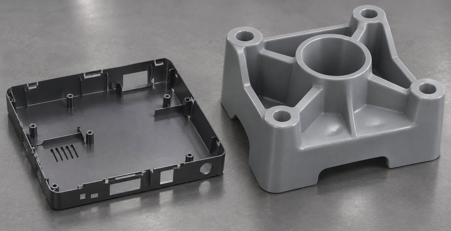
A resin datasheet might recommend a melt range of 260 to 300 degrees Celsius for PA66 — but which end of that range should you target? The pellets do not know and the datasheet cannot tell you, because the answer depends on something the resin manufacturer has never seen: your part. Wall thickness, flow-path length, gate location, number of cavities, and runner layout all create thermal demands that push you toward one end of the processing window or the other. Two molds running the same HDPE grade at the same HDPE melt temperature can produce completely different outcomes if one feeds a thin-wall food container and the other fills a thick-wall industrial cap. Geometry is the translator between what the resin needs and what the process must deliver.
Thin-Wall Molding and High-Flow Melt Requirements
When wall thickness drops below 1.0 mm, the race between melt flow and skin-layer solidification becomes the defining challenge. The moment molten polymer contacts a cooler mold surface, a frozen skin begins to form on the cavity wall. In a thick part, the central flow channel stays open long enough for the material to reach the end of fill comfortably. In a thin-wall part, that channel collapses fast — sometimes in fractions of a second — and the flow front can freeze before the cavity is full.
Higher melt temperatures reduce viscosity, allowing the polymer to flow faster through narrow cross-sections before freezing. This is why thin-wall packaging, electronics housings, and connector bodies routinely process at the upper end of their resin's recommended range. A PP container with 0.6 mm walls might need a melt temperature of 260 to 270 degrees Celsius, while the same PP grade running a 2.5 mm structural bracket fills easily at 220 degrees. The polypropylene melting temp does not change between the two jobs — but the thermal energy the process must deliver certainly does.
The tradeoff is real, though. Pushing melt temperature higher to aid flow also extends cooling time, because the polymer enters the cavity carrying more thermal energy that the cooling system must extract before ejection. Cycle time lengthens. The risk of thermal degradation increases, especially for resins like PVC where the melting point of PVC compounds sits uncomfortably close to the degradation threshold. And for semi-crystalline materials, excessively hot melts can produce higher volumetric shrinkage that complicates dimensional control on precision parts. Thin-wall molding lives at the top of the processing window, but it demands vigilance about how close you are to the ceiling.
Thick-Wall Parts and the Case for Lower Melt Temperatures
Thick-wall parts — anything above 3.0 mm, and especially parts exceeding 5.0 mm — face the opposite set of challenges. The cavity fills easily because the flow channel is wide and stays open for a long time. The problem shifts from "can the material get there" to "can we control what happens after it arrives."
Higher melt temperatures in thick sections mean more thermal energy trapped in the part core, which takes longer to cool. Cooling time does not scale linearly with wall thickness — it scales roughly with the square of the thickness. Double the wall and cooling time roughly quadruples. Every unnecessary degree of melt temperature above the minimum needed for a good fill adds to that cooling burden, dragging out cycle times and increasing production cost.
More importantly, thick sections are prone to sink marks and internal voids. As the core material cools and contracts after the skin layer solidifies, the shrinkage pulls the surface inward over thick ribs and bosses. Running at the lower end of the melt range reduces the total volumetric shrinkage the material undergoes during cooling, which directly lessens sink depth. For semi-crystalline resins like HDPE, where the HDPE melting temperature range spans from 180 to 260 degrees Celsius and shrinkage rates can reach 3%, keeping the melt closer to the lower boundary pays measurable dividends in part quality and dimensional consistency.
The risk of going too low? Incomplete packing. If viscosity is too high when the gate freezes, the holding phase cannot push enough material into the cavity to compensate for shrinkage — and you get the very sink marks and voids you were trying to avoid. Poor surface finish and weak weld lines also emerge when the melt lacks enough thermal energy to replicate mold-surface texture or fuse properly where flow fronts meet. The sweet spot for thick parts sits in the lower half of the recommended range, not at the absolute minimum.
Multi-Cavity and Hot-Runner Temperature Uniformity
Single-cavity molds allow you to focus all your attention on one flow path and one thermal profile. Multi-cavity tools introduce a different dimension of complexity: every cavity in the mold must receive melt at the same temperature, pressure, and flow rate to produce parts with identical dimensions and weight. When melt temperature varies from cavity to cavity, parts from the hotter cavities shrink differently than parts from the cooler ones — and you end up sorting, rejecting, or accepting dimensional variation that should not exist.
In geometrically balanced runner systems — where every cavity sits the same distance from the sprue — you might expect uniform fill. But as research published by Plastics Today explains, flow imbalance can occur even in seemingly geometrically balanced runner designs. The cause is non-uniform melt temperature distribution within the runner itself. As polymer flows through the runner, shear rate is higher near the walls than at the center. This friction generates viscous heating that can exceed 20 degrees Celsius in certain conditions. When the melt splits at a branch point, the hotter material on the inside of the turn and the cooler material on the outside do not remix — they separate asymmetrically into different sub-runners. Hotter melt flows faster, reaching some cavities sooner and at lower viscosity than others.
Hot-runner systems add another layer of control — and another potential source of imbalance. Each manifold channel and nozzle tip has its own heater and thermocouple, and any variation in heater output, thermocouple calibration, or heat loss to the mold steel produces temperature differences that directly affect melt viscosity at the gate. A 5-degree difference in nozzle-tip temperature between two drops may sound insignificant, but for materials with a strong viscosity-temperature dependency like PMMA or PC, that difference can produce measurable cavity-to-cavity weight variation. Manifold heater placement, insulation quality, and the thermal conductivity path between heater and melt channel all influence how uniformly the system delivers material to each gate.
Valve-gate systems offer timing-based control that can synchronize cavity fill regardless of minor temperature differences, but they add mechanical complexity and maintenance requirements. Melt-rotation devices — specialized inserts at runner branch points that reposition the melt's thermal profile — provide a hardware-based approach to normalizing temperature distribution without relying on active controls.
The practical starting point for any new application is the same regardless of geometry: begin at the midpoint of the resin manufacturer's recommended melt range, then adjust based on what the part demands. The following rules of thumb provide a reliable framework for those adjustments:
- Thin walls below 1.0 mm: Start at the upper third of the recommended melt range. Increase in 5-degree increments if short shots or flow hesitation occur. Monitor closely for degradation signs as you approach the ceiling.
- Long flow paths (flow-length-to-thickness ratio above 150:1): Raise melt temperature 10 to 20 degrees above midpoint to maintain flow front mobility. Consider higher mold temperature as a complementary strategy to keep the skin layer from freezing prematurely.
- Thick walls above 3.0 mm: Target the lower third of the melt range to minimize shrinkage, sink marks, and cooling time. Verify adequate packing by monitoring part weight and gate-seal studies.
- Complex geometries with multiple flow splits, bosses, or ribs: Increase melt temperature 5 to 10 degrees above midpoint to ensure the melt maintains enough fluidity to navigate direction changes and fill around obstructions.
- Multi-cavity molds (4+ cavities): Prioritize temperature uniformity over absolute temperature. Use melt-rotation inserts or valve-gate sequencing to equalize cavity fill. Verify part weight across all cavities — not just one sample cavity.
- Hot-runner systems: Calibrate each nozzle-tip thermocouple individually. Check for manifold dead spots where material can stagnate and degrade. Match manifold temperatures to the target melt range, not simply to the barrel set points.
- Short, simple flow paths with thick walls: Lower melt temperature toward the bottom third of the range. The cavity fills easily, so the priority shifts to minimizing cycle time and shrinkage rather than maximizing flow.
Every one of these adjustments changes the thermal demand placed on the polymer — and when that demand is not met, defects follow in predictable patterns. The relationship between melt temperature and specific defect types is consistent enough to map systematically, giving molders a diagnostic tool that works backward from the symptom to the thermal cause.
Troubleshooting Defects Linked to Melt Temperature
A part comes off the press with burn marks along the last-to-fill edge. Another shows silvery streaks fanning out from the gate. A third flashes at the parting line on one cavity but not the others. Each of these defects tells a story, and in most cases, the plot leads back to what temperature the plastic actually reached — or failed to reach — inside the barrel and during injection. The challenge is reading the story correctly, because many defects share overlapping symptoms yet demand opposite corrective actions. Lowering melt temperature to fix flash, for example, can push the process straight into short shots if viscosity climbs too high.
The troubleshooting map below connects nine of the most common injection molding defects to their melt-temperature relationships, identifies the contributing factors that often blur the diagnosis, and prescribes corrective actions that address root cause rather than symptoms. Use it as a diagnostic starting point — not a replacement for systematic process analysis, but a reference that helps you ask the right questions first.
Defect-to-Melt-Temperature Troubleshooting Map
| Defect | Melt Temperature Relationship | Other Contributing Factors | Corrective Action |
|---|---|---|---|
| Burn Marks / Discoloration | Melt temp too high causes thermal degradation — chain scission, oxidation, and off-gassing produce charred, discolored areas. Excessive residence time at elevated temperatures compounds the effect. | Trapped air from poor venting; excessive injection speed compressing air pockets; stagnant material in dead zones of hot runner or nozzle. | Reduce barrel temperatures in 5 °C increments. Verify actual melt temperature with a probe. Decrease injection speed to allow air to escape through vents. Clean or redesign venting paths. Reduce cycle time to shorten residence time. |
| Splay / Silver Streaks | Moisture in hygroscopic resins reacts with the polymer backbone at melt temperature, triggering hydrolytic degradation and gas generation. Alternatively, melt temp too high volatilizes additives or low-molecular-weight fractions. | Inadequate drying; contaminated regrind; excessive screw RPM creating shear-induced volatiles. | Verify material moisture content before processing — this is step one, not step three. If moisture is within spec, reduce melt temperature in 5 °C increments. Lower screw RPM to reduce shear heating. |
| Flash | Melt temp too high reduces viscosity below what clamp tonnage can contain, allowing material to seep past the parting line, ejector pins, or slide interfaces. | Insufficient clamp force; worn or damaged mold faces; excessive injection pressure or pack pressure; over-sized shot weight. | Lower melt temperature to increase viscosity. Verify clamp tonnage is adequate for projected cavity area. Inspect parting-line surfaces for wear or damage. Reduce pack pressure if flash persists after temperature reduction. |
| Short Shots | Melt temp too low raises viscosity, preventing the flow front from reaching the end of fill before the skin layer freezes. At what temperature will plastic melt enough to fill complex or thin-wall geometries? Often higher than the lower bound of the datasheet suggests. | Insufficient injection pressure or speed; inadequate venting trapping air pockets; gate too small or poorly located; cold mold surface freezing flow front prematurely. | Raise melt temperature in 5 °C increments. Increase injection speed to outrun skin-layer formation. Raise mold temperature to slow the freeze-off rate. Check venting adequacy at the last point of fill. |
| Warpage | Large melt-to-mold temperature differential creates steep thermal gradients, locking in uneven shrinkage and residual stress. Asymmetric cooling between core and cavity side amplifies the effect. | Non-uniform wall thickness; inadequate cooling-channel layout; anisotropic shrinkage in semi-crystalline or fiber-filled resins; premature ejection before the part is dimensionally stable. | Balance melt and mold temperatures as an integrated system — reduce the differential. Equalize cooling on core and cavity sides. Extend cooling time if needed. For semi-crystalline resins, raise mold temperature to promote uniform crystallization. |
| Sink Marks | Melt temp too high increases total volumetric shrinkage during cooling, deepening sink over thick sections. Melt temp too low inhibits effective packing because viscosity rises and the gate freezes prematurely. | Thick ribs or bosses exceeding 60% of adjacent wall thickness; insufficient pack pressure or hold time; gate freeze-off before packing is complete. | Target mid-range melt temperature. Increase pack pressure and hold time. Extend gate-seal time by enlarging gate or optimizing gate location. Redesign thick sections to reduce rib-to-wall ratio. |
| Brittleness | Excessive melt temperature or prolonged residence time causes irreversible chain scission that reduces molecular weight and destroys impact strength and elongation. | Wet hygroscopic material undergoing hydrolysis; degraded regrind in the feed stream; excessive shear from worn screw or aggressive compression ratio. | Measure melt temperature and compare to the upper limit on the resin datasheet. Reduce barrel temperatures and screw RPM if the reading is above target. Verify drying conditions. Evaluate regrind percentage and quality. |
| Poor Surface Gloss | Melt temp too low prevents the polymer from conforming closely to the polished mold surface before the skin solidifies. The melt freezes before it can replicate fine surface details. | Low mold temperature; slow injection speed allowing premature skin formation; mold surface contamination or wear. | Raise melt temperature in 5 °C increments. Increase mold temperature to slow skin-layer freezing. Increase injection speed through the gate area. Inspect and re-polish mold surfaces. |
| Black Specks | Degraded, carbonized polymer from stagnant zones in the barrel, hot runner, or nozzle where material sits at melt temperature long enough to oxidize and char. What temp will plastic melt versus what temp will it carbonize can differ by a surprisingly small margin when residence time is extended. | Dead spots in manifold channels; worn check ring allowing material to accumulate behind the screw tip; infrequent purging during production; contamination from previous resin left in the system. | Purge the barrel and hot-runner system thoroughly. Inspect screw tip, check ring, and nozzle adapter for dead zones. Reduce residence time by matching machine size to shot volume (ideally 40–65% barrel utilization). Implement preventive purging schedules between production runs. |
A pattern emerges from this map: roughly half the defects point toward melt temperature being too high, while the other half point toward it being too low. That is exactly why experienced molders resist the temptation to make large temperature swings when troubleshooting. A 15-degree jump to fix a short shot may solve the fill problem while introducing flash, splay, or degradation elsewhere. Small, measured adjustments of 5 degrees Celsius — verified each time with an actual melt-temperature measurement — keep the process within the safe corridor.
Thermal Degradation at the Molecular Level
When a molder asks what temperature melts plastic, the implicit assumption is that the polymer transforms from solid to liquid and stays chemically intact. That assumption holds — but only up to a point. Every thermoplastic has a degradation ceiling above which the molecular chains themselves begin to break apart, and that ceiling is not always far above the processing floor.
Three mechanisms drive thermal degradation, and all are irreversible:
- Chain scission: Covalent bonds along the polymer backbone absorb enough thermal energy to rupture. Long chains break into shorter fragments, directly reducing the average molecular weight of the material. As Beaumont Technologies emphasizes, a processor's number one responsibility is to preserve the molecular weight of the polymer during molding — because once chains are broken, performance properties decay proportionally. Even a 10% reduction in average molecular weight, corresponding to roughly a 40% increase in melt flow rate, can measurably compromise impact strength, fatigue resistance, and chemical resistance.
- Oxidative degradation: Trapped oxygen — from air entrained in the pellet feed, incomplete venting, or decompression during screw pullback — reacts with the polymer at elevated temperatures. These oxidative reactions attack chain bonds and pendant groups, producing discoloration (yellowing in PC, browning in nylon) and off-gassing. Oxidation accelerates rapidly with each degree of temperature increase, which is why it often manifests suddenly rather than gradually when the process drifts a few degrees past the safe limit.
- Volatile off-gassing: As chains break and oxidation reactions proceed, low-molecular-weight fragments, additives, and reaction byproducts vaporize. These gases create internal pressure within the melt that can blow out through the flow front as splay, form bubbles trapped as voids, or deposit on the mold surface as plate-out that fouls venting and contaminates subsequent shots.
The compounding nature of these mechanisms is what makes thermal degradation so dangerous. Chain scission produces shorter chains with lower viscosity. Lower viscosity reduces the shear stress the melt experiences at the same screw RPM — but the heater bands are still delivering the same thermal energy to a material that now needs less. The temperature climbs further. More chains break. The cycle accelerates. Degradation studies conducted at the American Injection Molding Institute demonstrated this compounding effect clearly: independently increasing melt temperature, residence time, or moisture content each raised melt flow rate (an indicator of molecular weight loss), but combining multiple factors produced exponential increases — a 614% MFR increase in polycarbonate when high melt temperature, long residence time, and elevated moisture content converged simultaneously.
When the Problem Is Not Temperature Alone
The troubleshooting table above lists "Other Contributing Factors" for a reason. Melt temperature is rarely the sole cause of any defect — it operates within a system of interacting variables. Flash might originate from excessive melt temperature, but it could just as easily come from worn mold faces that no longer seal at the parting line. Splay might look like a thermal problem, but a failing desiccant dryer is far more likely to be the root cause in moisture-sensitive resins. Black specks appear to come from overheating, but their real origin is often a dead zone in a manifold channel where material stagnates and carbonizes over hours or days.
The key diagnostic discipline is isolating variables rather than chasing symptoms. Measure actual melt temperature first — always. If the reading falls within the resin's recommended range, temperature is probably not the primary cause, and attention should shift to moisture content, venting, clamp force, mold condition, or material handling. If the reading falls outside the range, correct it and re-evaluate before investigating secondary factors.
That diagnostic approach — systematic, measurement-driven, and rooted in understanding what the polymer actually experiences — is exactly the mindset behind a proper melt-temperature optimization procedure. Building a repeatable workflow that qualifies the right temperature for each new resin and mold combination saves time, reduces scrap, and prevents the trial-and-error guessing that burns through material and patience in equal measure.
Systematic Melt Temperature Optimization for New Applications
Troubleshooting defects after they appear is necessary — but it is also reactive. The better approach is to qualify the right melt temperature before problems start, using a structured procedure that accounts for resin behavior, machine characteristics, and part requirements from the first shot. Most molders rely on tribal knowledge, datasheet midpoints, or whatever worked on a similar job last year. That gets you close, but "close" is where dimensional drift, cosmetic rejects, and unexplained cycle-time creep live. A repeatable optimization workflow eliminates the guesswork and gives you a documented process window you can defend to quality auditors, replicate across shifts, and transfer between machines with confidence.
The methodology below is designed for qualifying a new resin, a new mold, or a new resin-mold combination. It works equally well for PVC melting temp setups on commodity packaging tools and PEEK qualifications on aerospace components — because the underlying logic applies to every thermoplastic. Follow the steps in sequence. Skipping ahead to temperature adjustments without verifying material preparation or measuring actual melt conditions is how processes start on the wrong foundation and never recover.
A Ten-Step Melt Temperature Optimization Procedure
- Review the resin datasheet thoroughly. Before touching the machine, pull the technical datasheet (TDS) for the exact grade you are running — not a generic family datasheet, but the specific product number. Identify the recommended melt temperature range, mold temperature range, maximum allowable residence time, drying requirements (if hygroscopic), and any processing cautions noted by the manufacturer. For filled or reinforced variants, note whether the supplier specifies a different melt range than the unfilled base resin. This step takes five minutes and prevents hours of trial-and-error chasing a target that was never appropriate for the material. Whether you are setting up an HDPE melting temp profile for a simple cap or dialing in a glass-filled nylon for an under-hood bracket, the datasheet defines the boundaries of your playing field.
- Verify that material drying meets specification. For hygroscopic resins — nylon, PC, PET, PBT, TPU, PMMA, PEI — confirm that the dryer has reached its target temperature, that the dew point is at or below -40 degrees Celsius, and that the material has been drying for the minimum time specified on the datasheet. Pull a moisture sample and test it with a moisture analyzer if one is available. Do not assume the dryer is performing correctly because the display says so; desiccant beds degrade, heaters fail, and hoppers lose seals. As melt preparation experts emphasize, at a given melt temperature every plastic material will degrade when held beyond a certain time — and moisture accelerates that degradation dramatically. Skipping this verification is the single most common source of preventable scrap in hygroscopic-resin processing.
- Set barrel zone profile with a graduated rear-to-front increase, targeting the midpoint of the recommended melt range at the nozzle. Begin with Zone 1 (feed) at the lowest setting — typically 15 to 30 degrees Celsius below the nozzle target — and increase progressively through Zones 2 and 3 to reach the midpoint of the resin's recommended range at the nozzle zone. For shear-sensitive amorphous resins like PC or PMMA, a flatter profile may be more appropriate, while semi-crystalline resins like nylon or POM generally respond well to a standard ramp. The midpoint is your starting position — not your final answer — because actual melt temperature will differ from set points due to shear heating and residence-time effects.
- Run initial shots at moderate screw RPM and back pressure. Set screw rotation speed to a moderate value — typically producing a recovery time that finishes within 70 to 80 percent of the cooling phase, leaving a small buffer before the mold opens. Set back pressure at a moderate baseline (roughly 5 to 10 bar hydraulic, or the equivalent in specific pressure). These conservative starting points minimize shear-induced overheating while still producing a reasonably homogeneous melt. Run several cycles to allow the barrel to thermally stabilize before evaluating anything.
- Measure actual melt temperature with a pyrometer probe and compare to set points. Perform an air-shot measurement as described in the set-point versus actual-temperature discussion earlier in this article. Insert a needle probe into the center of the purge mass and record the peak reading. Compare this value to the nozzle set point and to the midpoint of the resin's recommended range. The delta between set point and actual reading quantifies how much shear and residence-time effects are contributing to your melt energy — information that no controller screen provides. If you are processing at the recommended temp to melt plastic for a given resin, the probe reading should fall within the datasheet's melt range. If it does not, you have a baseline correction to make before evaluating parts.
- Evaluate parts for fill, surface quality, dimensional accuracy, and visual defects. Collect parts from several consecutive shots after the process has stabilized. Inspect for short shots, flash, splay, burn marks, sink marks, weld-line visibility, surface gloss, and overall dimensional conformance. Weigh the parts to check for shot-weight consistency. This initial evaluation establishes whether the midpoint melt temperature produces acceptable results or whether adjustment is needed — and in which direction.
- Adjust melt temperature in 5 degree Celsius increments based on part evaluation. If parts show short shots, flow hesitation, poor weld-line knit, or dull surface finish, raise the melt temperature by 5 degrees — either by increasing the nozzle and front-zone set points or by modestly increasing screw RPM or back pressure. If parts show flash, burn marks, excessive stringing, or discoloration, lower the temperature by 5 degrees using the reverse approach. Re-measure actual melt temperature after each adjustment. Never change more than one variable at a time. This disciplined approach isolates cause and effect and prevents the oscillating overcorrections that waste material and time.
- Co-optimize mold temperature alongside melt temperature. For semi-crystalline resins — PP, PA6, PA66, PBT, PET, PPS, PEEK — mold temperature directly controls crystallization behavior and therefore mechanical properties, dimensional stability, and warpage. Raise or lower mold temperature in conjunction with melt temperature adjustments. Higher mold temperatures promote crystallinity and reduce residual stress in semi-crystalline parts; they also improve flow length and surface replication in both amorphous and semi-crystalline materials. For amorphous resins like ABS, PC, and PMMA, elevated mold temperatures reduce molded-in stress that can cause cracking in service or during secondary operations like painting or chemical bonding. The melt and mold temperatures are two halves of one thermal system — optimizing one without the other leaves performance on the table.
- Lock the process window and document upper and lower melt-temperature limits. Once part quality, dimensions, and cosmetics meet specifications, identify the boundaries of the acceptable range. Raise the melt temperature incrementally until the first defect appears on the high side (typically flash, discoloration, or stringing), then lower it incrementally until the first defect appears on the low side (typically short shots, poor gloss, or hesitation marks). The range between these two failure boundaries is your process window. Document the center point, the upper limit, the lower limit, and the corresponding barrel zone profile, screw RPM, back pressure, and mold temperature. This documentation is what makes the process transferable — to another shift, another machine, or another facility — and auditable for quality-system compliance.
- Validate screw and barrel condition if target melt temperature cannot be reached or held consistently. This is the step that separates process optimization from process frustration. If, after working through steps one through nine, you still cannot achieve the target melt temperature — or the measured temperature drifts unpredictably from shot to shot despite stable settings — the plasticizing hardware itself is the likely bottleneck. Measure screw flight outside diameters and barrel bore dimensions. Inspect the check ring for wear and sealing performance. Evaluate whether the screw geometry (compression ratio, L/D, mixing elements) matches the thermal and rheological demands of the resin.
When Process Adjustments Are Not Enough
Step ten deserves special emphasis because it addresses the root cause that the previous nine steps cannot fix. Worn screw flights, enlarged barrel bores, and mismatched compression ratios set a ceiling on what your process adjustments can achieve. You can raise zone temperatures, increase back pressure, and push screw RPM to their limits — but if the screw has lost its flight geometry or the barrel clearance has doubled from wear, those adjustments are compensating for hardware that has passed its useful life. As Jeff Kuhman of Glycon Corp. explains, as clearances between the screw flight OD and barrel bore increase, melting efficiency decreases — and operators tend to compensate with incremental tweaks to screw speed, barrel temperatures, and back pressure that go unnoticed until they dramatically impact part quality or productivity.
The practical indicators that hardware — not process settings — is the limiting factor include:
- Measured melt temperature consistently falls short of the target despite maximum reasonable zone profiles and back pressure.
- Shot-to-shot melt temperature swings exceed 5 degrees Celsius under stable controller settings.
- Screw recovery time has gradually increased over weeks or months of production.
- Cushion position is unstable or drifting, indicating check-ring leakage.
- Black specks or color streaks persist despite thorough purging — suggesting material retention in worn clearances or dead zones.
When these symptoms converge, the screw and barrel become the last — and most important — link in the optimization chain. Replacing a worn general-purpose screw with a purpose-built unit matched to the resin's thermal behavior, the machine's specifications, and the job's shot-volume requirements restores the precision that wear has gradually eroded. NANHAIYA's custom injection molding screw barrels exemplify this application-specific approach: their technical review evaluates screw geometry, wear patterns, melting and mixing performance, and material-retention concerns before manufacturing a replacement matched to the specific machine, resin, and shot requirements. That engineering-review process ensures the new hardware addresses the root cause rather than simply duplicating the geometry that wore out — which may never have been optimal for the application in the first place.
The ten-step procedure above is not a one-time exercise. Revisit it whenever you change resin grades, modify the mold, move a job to a different machine, or notice the process drifting beyond its documented window. Each pass through the workflow refines your understanding of where the polymer, the machine, and the part geometry intersect — and that understanding is ultimately what separates consistent, capable production from the reactive troubleshooting cycle that consumes too many molding operations.
Frequently Asked Questions About Injection Molding Melt Temperature
1. What is the difference between barrel set temperature and actual melt temperature in injection molding?
Barrel set temperature is the target heat level programmed into the machine controller for each heating zone, but it only reflects the temperature of the barrel steel — not the polymer inside. Actual melt temperature is the real thermal state of the molten plastic as it exits the nozzle. The gap between the two can range from 5 to 30 degrees Celsius due to shear heating from screw rotation, back pressure effects, and residence time variations. Research has shown nozzle melt temperatures can spike as much as 44 degrees Celsius above barrel readings during injection. To measure the true value, molders perform an air-shot purge and insert a pyrometer probe into the center of the molten mass. Without this direct measurement, process decisions are based on incomplete data, which often leads to unexplained dimensional drift and cosmetic defects.
2. What temperature does plastic melt at for common injection molding resins?
Melt temperatures vary widely by resin family. Commodity plastics process at lower ranges — LDPE and LLDPE at 160 to 240 degrees Celsius, PP at 200 to 280 degrees Celsius, and GPPS at 180 to 260 degrees Celsius. Engineering resins require higher heat: polycarbonate runs at 280 to 320 degrees Celsius, PA66 nylon at 260 to 295 degrees Celsius, and PET at 260 to 290 degrees Celsius. High-performance polymers push even further, with PEEK demanding 360 to 400 degrees Celsius. Filled or reinforced grades typically require an additional 10 to 20 degrees Celsius above the unfilled base resin due to increased viscosity from glass fibers or mineral fillers. Always confirm the exact range on the specific grade's technical datasheet.
3. Why does moisture in plastic pellets cause defects at melt temperature?
Hygroscopic resins such as nylon, polycarbonate, PET, and TPU absorb water molecules into their molecular structure. When these wet pellets reach processing temperatures above approximately 240 degrees Celsius, the water does not simply evaporate — it chemically attacks the polymer backbone through a reaction called hydrolytic degradation. This reaction breaks long polymer chains into shorter fragments, permanently reducing molecular weight, impact strength, and elongation. The vaporized moisture also creates gas pockets that surface as splay, silver streaks, and internal voids. This damage is irreversible regardless of any subsequent process adjustment, which is why verifying moisture content before processing — not after defects appear — is essential for every hygroscopic resin.
4. How do screw speed and back pressure affect actual melt temperature?
Screw speed and back pressure both add mechanical shear energy to the polymer independently of what barrel heater bands supply. Higher screw RPM increases the shear rate between flights, barrel wall, and melt, potentially adding 10 to 20 degrees Celsius to actual melt temperature. Back pressure extends the duration of shearing during screw recovery, improving melt homogeneity but also generating additional heat. When both are raised simultaneously, the thermal effect compounds rather than simply adding together. This is why experienced molders adjust these parameters incrementally and re-measure actual melt temperature after each change. When worn screw flights or barrel bores widen the clearance between components, shear efficiency drops and operators often compensate by raising these settings further — masking a hardware problem with process band-aids.
5. How should I optimize melt temperature for a new mold or resin?
A systematic ten-step approach starts with reviewing the resin datasheet for the exact grade, verifying material drying meets specification, and setting a graduated barrel zone profile targeting the midpoint of the recommended melt range. Run initial shots at moderate screw RPM and back pressure, then measure actual melt temperature with a pyrometer probe. Evaluate parts for fill, surface quality, and dimensional accuracy. Adjust melt temperature in 5 degree Celsius increments — upward for short shots or poor gloss, downward for flash or degradation signs. Co-optimize mold temperature alongside melt temperature, especially for semi-crystalline resins where crystallization control matters. Document the upper and lower limits that produce acceptable parts to define your process window. If target melt temperature cannot be achieved or held consistently, inspect screw and barrel condition as the final diagnostic step.
Written by
Nanhaiya Technical Team
Zhoushan Nanhaiya Plastic Machinery Co., Ltd.
The Nanhaiya technical team supports screw and barrel manufacturing projects through application review, technical communication, custom manufacturing coordination, and production and quality control.
Discuss Your Application
Related Articles
More insights on screw barrel technology and plastics processing.
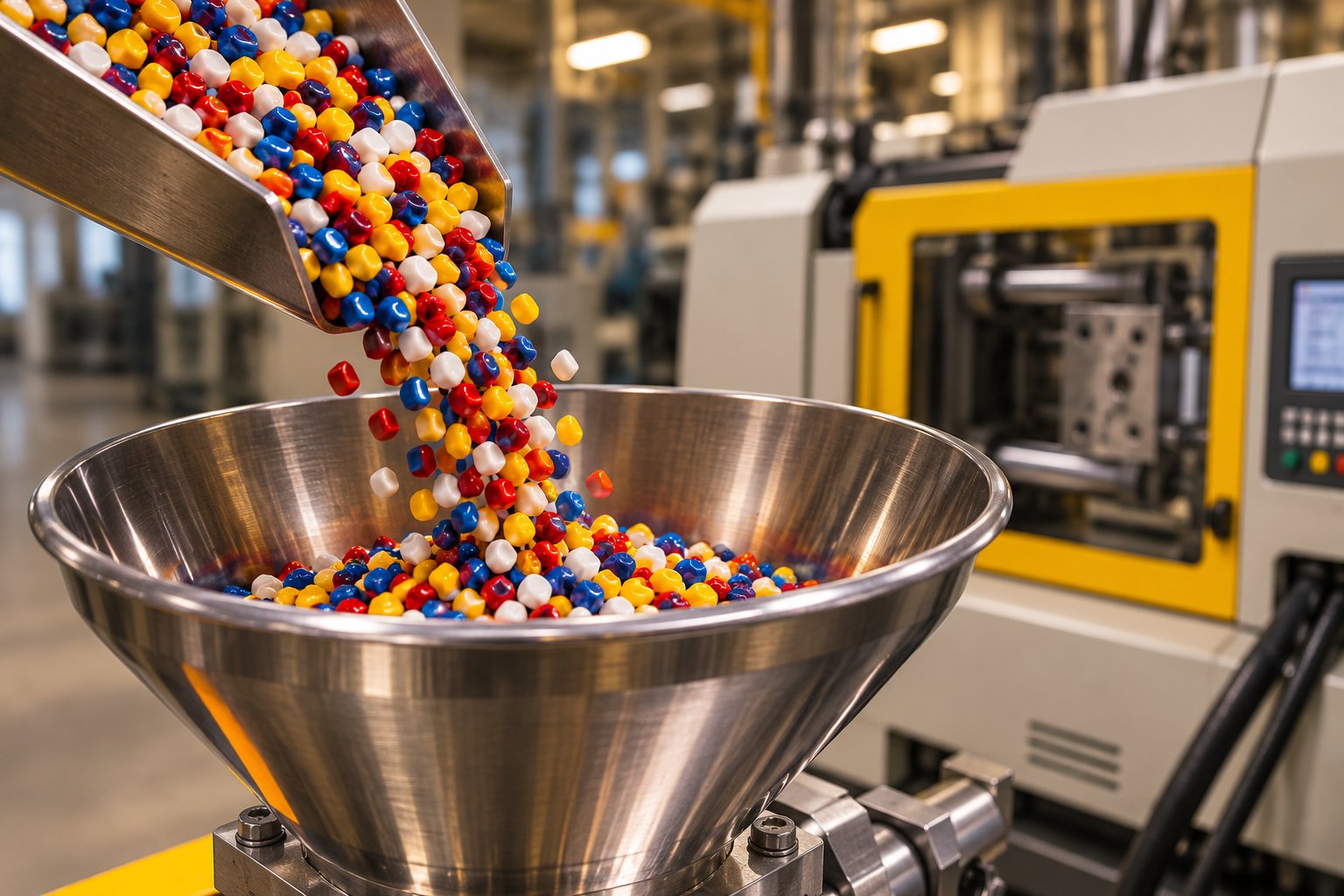
Injection Molding Color Mixing: From Streaks to Flawless Consistency
Nov 19, 2026
Master injection molding color mixing with expert guidance on colorant types, screw design, process parameters, defect troubleshooting, and Delta E QC protocols.
Read Article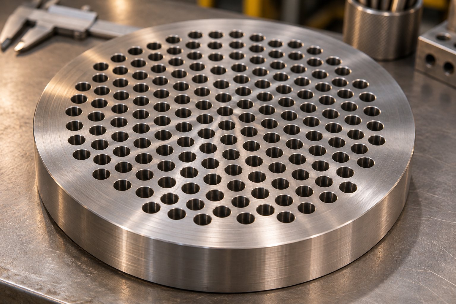
Wrong Extruder Breaker Plate? Spot the Signs Before Scrap Piles Up
Nov 19, 2026
Learn how to select, size, and maintain your extruder breaker plate. Covers hole geometry, pressure drop, polymer-specific specs, and troubleshooting tips.
Read Article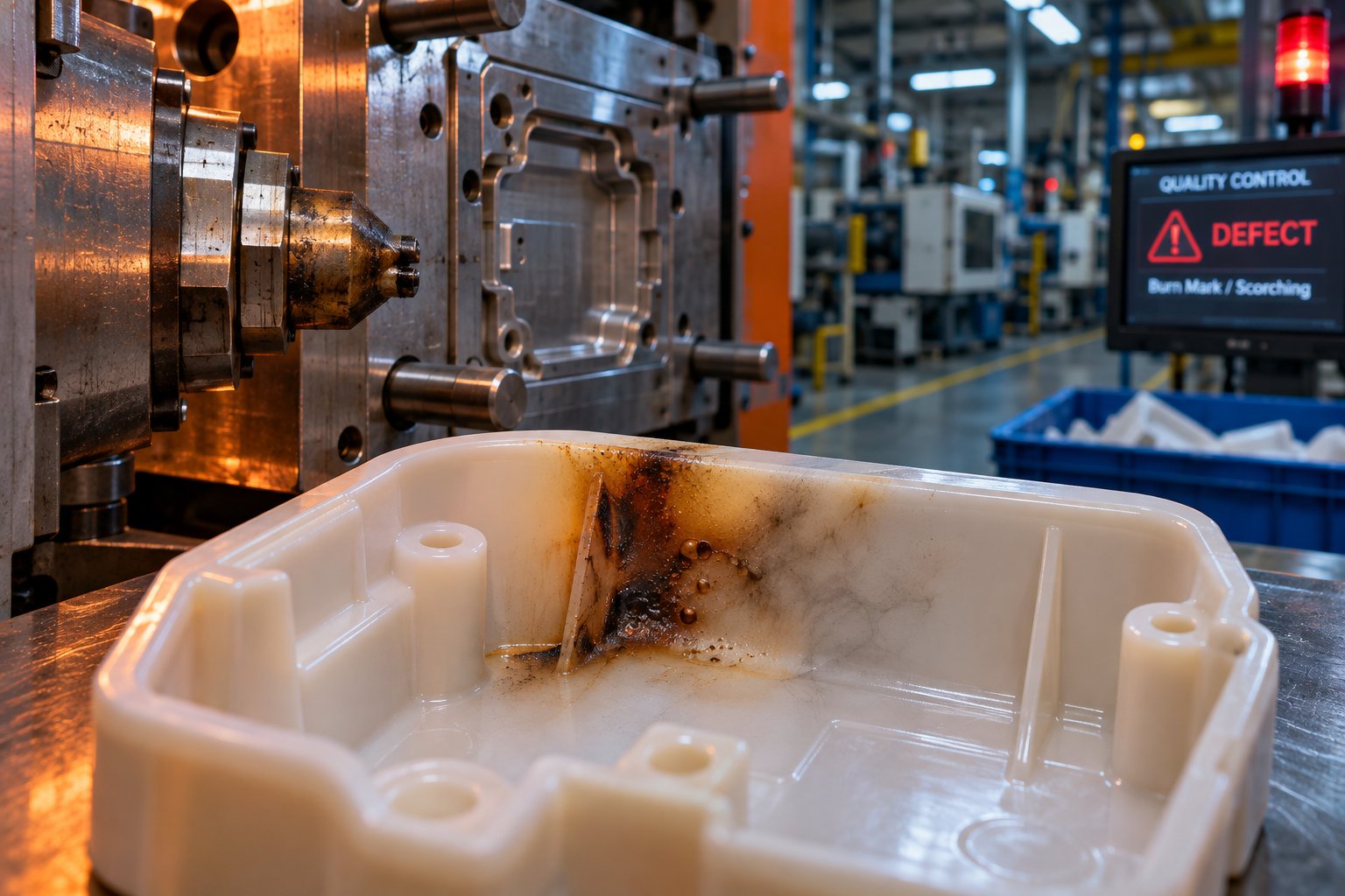
Injection Molding Burn Marks: Diagnose the Root Cause, Kill the Defect
Nov 19, 2026
Learn how to diagnose and fix injection molding burn marks. Covers gas-trap burns, material degradation, moisture defects, mold venting, and screw barrel wear solutions.
Read ArticleLooking for something else?
Search by material, symptom or product and jump straight to the relevant page.
These are navigation suggestions based on keyword matching — not a quotation, not a delivery commitment, and not a substitute for engineering review. Final specification is confirmed by our engineers against your drawings and processed material.
Need help with screw barrel selection?
Share your machine model, processed material and application. Our team can help with pricing and technical support.