

What Is Die Drool and Why the Terminology Matters
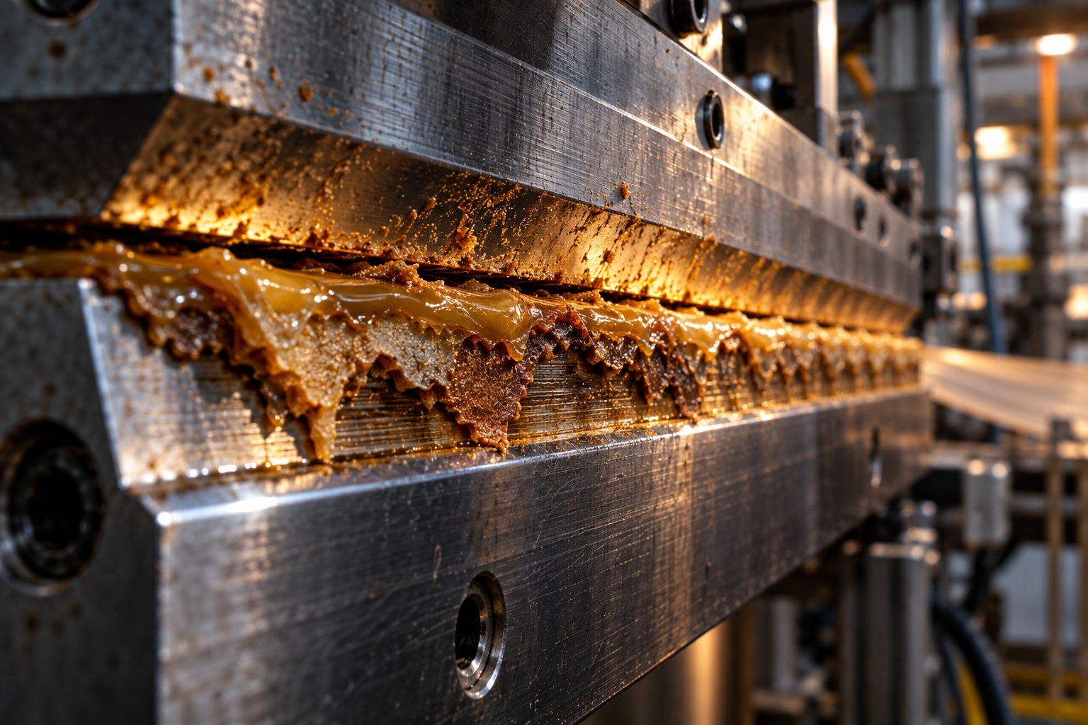
Imagine you are running a steady extrusion line. Output looks good, melt pressure is stable, and the downstream equipment hums along without a hiccup. Then you glance at the die exit and spot it: a slow, stubborn accumulation of material clinging to the lip, growing thicker by the hour. Left unchecked, that buildup will eventually break free, contaminate your extrudate, and send finished product straight to the scrap bin. What you are looking at is die drool, and it is one of the most persistent headaches in polymer extrusion.
Die Drool Definition and Core Concept
At its simplest, die drool is the unwanted accumulation of material on or near the die exit during extrusion. But a closer look reveals something more complex than a simple "mess at the die face." The deposit is typically a mixture of degraded polymer, low-molecular-weight species, additives, and condensed volatiles that migrate to the die lip over time. As the bulk melt flows through the die channel and exits, these smaller, more mobile fractions separate from the main flow and collect on exterior surfaces. The result is a growing mass that can cause die lines, surface streaks, blockages, and even stress concentrators in the finished product.
Die drool is the unwanted buildup of degraded polymer, low-molecular-weight fractions, additives, and volatile condensates on the die exit surfaces during extrusion. It accumulates progressively during production runs, eventually contaminating the extrudate and causing surface defects, dimensional variation, and scrap.
The buildup itself can range from thin and runny to thick and fluffy. Thin, runny deposits often point to low-molecular-weight fractions that volatilize at the die exit and condense on the cooler die face. Thick, fluffy accumulations, on the other hand, tend to signal compatibility issues within the melt, partial foaming, or high stress inside the die. Understanding which type you are dealing with is the first step toward choosing the right corrective action rather than just scraping the lip and hoping for the best.
Industry Terminology You Should Know
Here is where things get confusing. Depending on who you talk to, this same phenomenon goes by half a dozen names:
- Die drool - the most widely recognized term in academic literature and among process engineers
- Die lip buildup (DLBU) - common in resin supplier technical bulletins
- Plate-out - frequently used in PVC extrusion circles, where lubricant migration dominates
- Die bleed - often heard on production floors, especially in film extrusion
- Die deposit - a more neutral, descriptive term used in some equipment manufacturer documentation
- Die beard - a vivid nickname that shows up in German-language research (translated from Dusenbart) and occasionally in English-language papers
These terms are used inconsistently across resin suppliers, equipment manufacturers, and academic publications. One supplier's "plate-out" is another's "die bleed," and the lack of standardized vocabulary makes cross-referencing troubleshooting guides unnecessarily difficult. Throughout this article, "die drool" serves as the primary term while acknowledging the aliases above. When you encounter any of these names in a product bulletin, a journal abstract, or a colleague's troubleshooting notes, recognize that they almost certainly describe the same underlying phenomenon.
Why does consistent terminology matter in practice? Because diagnosing the root cause of die drool in extrusion requires pulling information from multiple sources: resin data sheets, die design specifications, processing parameter logs, and sometimes academic research. If your team uses one term while your resin supplier uses another, critical information can slip through the cracks. Aligning on vocabulary is not just semantics; it is the foundation of effective communication between operators, engineers, and suppliers when production quality is on the line.
The real challenge, though, is not naming the problem. It is understanding the science that drives it, from the molecular behavior inside the melt to the process conditions that accelerate or suppress deposit formation.
Scientific Mechanisms Behind Die Drool: What Causes It and How to Avoid It
That stubborn buildup at the die lip does not appear out of nowhere. Several distinct mechanisms work simultaneously inside the melt and at the die exit to drive material out of the main flow and onto surfaces where it does not belong. You do not need a polymer science degree to grasp these mechanisms, but understanding them is the difference between guessing at fixes and targeting the actual root cause. Let's break it down into three core pathways.
Low-Molecular-Weight Species Migration
Picture the polymer melt flowing through your die channel. It is not a perfectly uniform fluid. Every commercial resin contains a population of shorter polymer chains, oligomers, and sometimes unreacted monomers mixed in with the longer, higher-molecular-weight molecules that give the material its strength. These smaller species behave very differently under flow.
When the melt moves through the die, shear stress is highest near the center of the flow and drops off toward the die wall. Those short, mobile chains respond to this stress gradient by migrating outward, concentrating near the lower-shear region at the wall surface. Think of it like a crowd exiting a stadium: smaller, faster people slip toward the edges while the larger group stays packed in the middle. Over time, these low-molecular-weight fractions slowly extrude past the die lip at extremely low rates, almost imperceptible during a single production hour, but steadily accumulating into visible deposits across a full run.
Research on HDPE extrusion has confirmed this mechanism directly. A study comparing two HDPE grades with virtually identical number-average and weight-average molecular weights demonstrated that the collected drool material was predominantly composed of the low-molecular-weight fraction of the resin. The researchers concluded that die drool in HDPE can be explained by flow-induced molecular weight fractionation, where the shear field inside the die physically separates shorter chains from the bulk and pushes them toward the exit surface. This is not a defect in the resin itself; it is a consequence of how polymer melts behave under realistic extrusion conditions.
Additive Blooming and Volatile Condensation
Low-molecular-weight polymer fractions are not the only contributors. Commercial resins are loaded with additives: slip agents, antioxidants, processing stabilizers, UV absorbers, and more. Many of these additives have limited compatibility with the base polymer at processing temperatures. As the melt approaches the die exit, these ingredients can bloom, migrating to the melt surface much like moisture beading on a cold glass. Near the cooler die lip, they condense and deposit, adding to the growing buildup.
Thermal and oxidative degradation creates another pathway entirely. When melt temperature runs too high or residence time in the extruder stretches too long, polymer chains break apart. This chain scission generates new volatile byproducts and additional low-molecular-weight fragments that did not exist in the original pellet. These degradation products are especially mobile and readily travel to the die exit, where the slight temperature drop at the lip provides a condensation surface. You'll notice that die drool often worsens toward the end of a long production run, and this is exactly why: degradation accumulates over time, continuously feeding fresh volatile material to the die face.
Imagine running your extruder at the upper end of the recommended melt temperature range while also pushing a resin with a generous antioxidant package. Both the additive bloom and the degradation-driven volatile condensation pathways are active simultaneously, and the result is accelerated buildup that no amount of lip scraping can keep ahead of.
The Role of Molecular Weight Distribution
Here is where resin selection becomes critical. Not all grades of the same polymer family produce the same amount of buildup, and the molecular weight distribution (MWD) is a major reason why.
MWD describes the spread of chain lengths in a resin. A broad distribution means the material contains a wide range of chain sizes, from very short to very long. A narrow distribution means most chains cluster around a similar length. Broader distributions inherently contain a larger population of those mobile, low-molecular-weight fractions that migrate to the die wall under shear. The wider the spread, the more "fuel" is available for the fractionation mechanism described above.
The HDPE research referenced earlier provides a compelling illustration. Between the two resins tested, the linear HDPE with higher melt elasticity and shear viscosity generated significantly more die drool than the long-chain branched HDPE, even though both had nearly identical polydispersity indices. Long-chain branching reduced melt elasticity, lowered the driving force for fractionation, and delayed the onset of the slip-stick flow regime that initiates drool formation. In practical terms, this means that two resins sitting side by side in a warehouse, both labeled "HDPE extrusion grade," can behave very differently at the die lip depending on their branching architecture and rheological characteristics.
For process engineers evaluating resin options, the takeaway is straightforward: ask your supplier for rheological data beyond basic melt flow rate. Melt elasticity, shear viscosity curves, and branching information are far better predictors of die drool behavior than MFR alone. When those data are not available, a simple trial comparing candidate grades under identical processing conditions will reveal differences quickly.
These three mechanisms rarely act in isolation. In most real-world extrusion operations, low-MW migration, additive bloom, and degradation-driven condensation overlap and reinforce each other. The relative contribution of each pathway shifts depending on the resin, the additive package, and the processing conditions, which raises a critical question: does the deposit form outside the die, inside the die, or both?
Internal Versus External Die Drool and Why the Distinction Matters
That question, whether the deposit forms on the outside of the die or within it, is more than academic. It changes the entire troubleshooting playbook. Yet most plant-floor discussions treat die drool as a single problem with a single fix. In reality, academic research and field experience both point to two fundamentally different categories, and confusing one for the other is one of the fastest ways to waste production time chasing the wrong solution.
External Die Drool at the Lip Surface
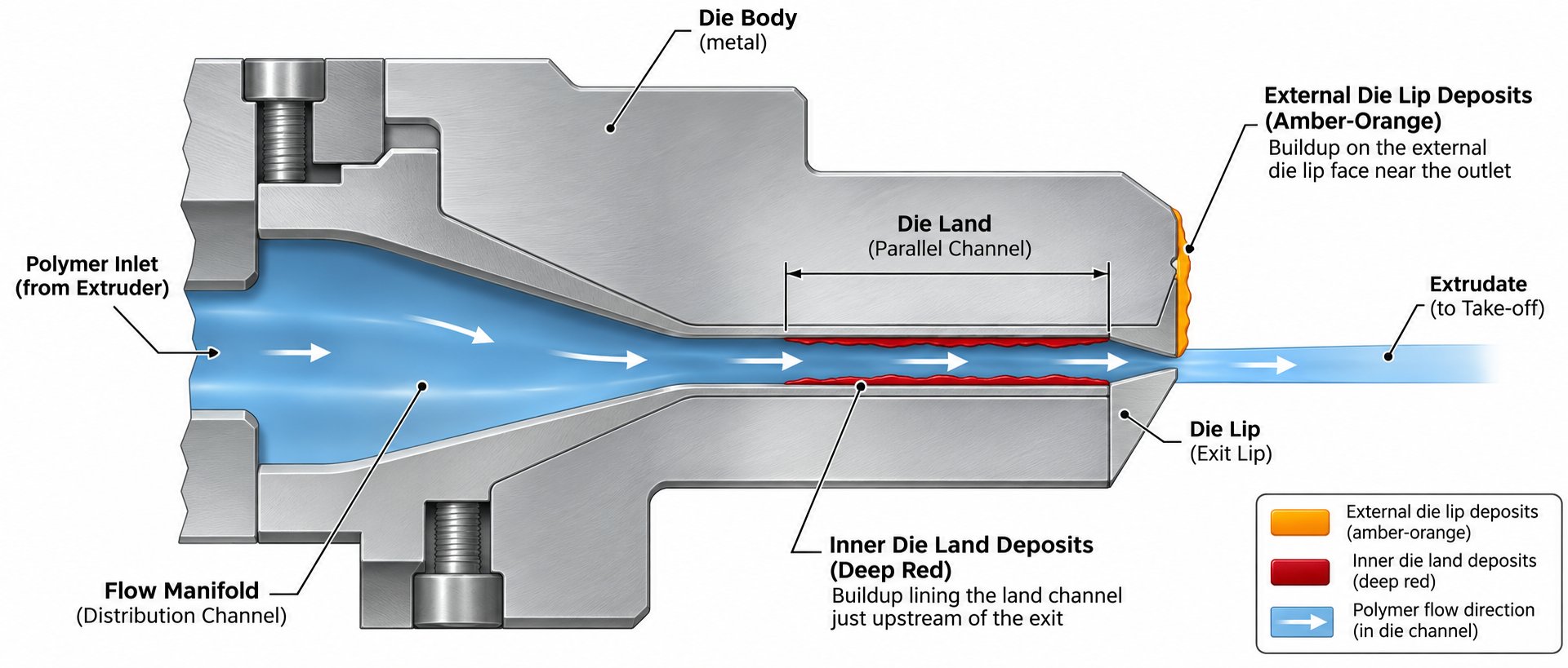
This is the type most operators recognize instantly. External die drool is the visible accumulation that forms on the outside face of the die lip, right where the extrudate exits into open air. You can see it, scrape it, and watch it grow back over the course of a production run.
The mechanisms covered in the previous section, low-molecular-weight species migration, additive blooming, and volatile condensation, all converge at this external surface. As the melt exits the die, shorter polymer chains and mobile additives that have migrated toward the die wall during flow are carried past the lip edge. The die face is slightly cooler than the melt, creating a condensation target for volatiles. Over hours of continuous operation, these deposits build layer upon layer, eventually growing large enough to contact the extrudate and break off in chunks.
Detection is straightforward: a visual inspection of the die face during operation reveals the buildup. The resulting product defects tend to be intermittent. Everything looks fine until a piece of accumulated material tears free and embeds itself in the product surface, creating contamination spots, gels, or streaks that appear suddenly rather than continuously.
Internal Die Drool Along the Land Channel
Internal deposits are a different beast entirely. These form inside the die land or flow channel itself, typically in stagnation zones where polymer sits too long, degrades, and adheres to the metal surface. Poor die geometry, sharp corners, and dead spots in the flow path are the usual culprits. Unlike external buildup, you cannot see internal deposits during operation, and that invisibility makes them far more dangerous from a diagnostic standpoint.
Research at Montanuniversitat Leoben on HDPE extrusion blow molding confirmed that die land length directly influences drool formation. Shorter die land lengths produced higher die drool accumulation, likely because the orientation and relaxation behavior of the polymer changed, and material did not have sufficient channel length to stabilize flow before exiting. This finding highlights how conditions inside the die channel, not just at the lip, play a decisive role in what ultimately appears as a surface quality problem.
The defects caused by internal deposits look different, too. Instead of intermittent contamination events, you'll notice persistent die lines, continuous surface roughness, or subtle dimensional changes in the extrudate. Operators frequently misattribute these symptoms to resin quality variation or temperature control issues because the defects do not have the obvious "chunk falling off" character of external drool. A die teardown during scheduled maintenance is often the only way to confirm internal deposits.
Side-by-Side Comparison: Internal vs. External
Because the corrective actions diverge so sharply, correctly identifying which type you are dealing with is the single most important first step. The following table lays out the key differences across five practical dimensions:
| Characteristic | External Die Drool | Internal Die Drool |
|---|---|---|
| Location | Outside face of the die lip | Inside the die land or flow channel |
| Primary Causes | Low-MW migration, additive blooming, volatile condensation at the cooler die exit | Stagnation zones, poor die geometry, degraded polymer adhering to internal metal surfaces |
| Detection Method | Visual inspection of the die face during production | Die teardown and inspection during scheduled maintenance; inferred from persistent product defects |
| Typical Product Defect | Intermittent contamination spots, gels, or surface streaks when deposits break free | Persistent die lines, continuous surface roughness, subtle dimensional variation |
| Recommended Corrective Action | Optimize melt and die temperatures, adjust additive package, apply polymer processing aids, improve die lip surface finish | Redesign die geometry to eliminate dead zones, polish internal flow channels, reduce residence time, shorten maintenance intervals for die cleaning |
Notice how different the corrective actions are. An operator dealing with external accumulation might add a fluoropolymer processing aid or adjust die temperature, both excellent strategies for that specific problem. But applying those same fixes to an internal deposit caused by a stagnation zone in the die channel accomplishes nothing. The deposit keeps forming in the dead spot regardless of what coats the lip surface. Conversely, tearing down and polishing the die land solves an internal issue but does nothing to address volatile condensation on the outside face.
This distinction also matters when evaluating how different resins interact with a given die. The same HDPE grade that produces primarily external buildup in one die geometry might generate internal deposits in a die with tighter corners and longer flow paths. The resin has not changed; the dominant drool mechanism has. Any serious troubleshooting effort needs to start by answering a deceptively simple question: where exactly is the deposit forming?
With that diagnostic foundation in place, the next logical consideration is which resins are most susceptible in the first place, and why the same processing line can behave very differently depending on the polymer family running through it.
Material-by-Material Die Drool Susceptibility Across Common Resins
Switch from one resin to another on the same extrusion line and you may feel like you are running an entirely different process. Buildup that barely registers with one polymer family can become a production-stopping headache with the next. That is because die drool build-up is not a universal constant; it is deeply resin-dependent, shaped by molecular architecture, additive chemistry, and thermal sensitivity. Understanding which materials carry the highest risk, and why, gives process engineers the most powerful material-side lever they can pull before touching a single process parameter.
Polypropylene Versus Polyethylene Drool Behavior
If you have run both PP and PE on the same line, you already know: polypropylene is the bigger troublemaker. Several factors stack the deck against it.
First, PP has a narrower processing window. Its melting point and degradation onset temperature sit closer together than polyethylene's, leaving less room for error. Push melt temperature even slightly too high and thermal chain scission accelerates, flooding the melt with mobile low-molecular-weight fragments that migrate to the die lip. Second, PP degrades through a different mechanism than PE. While polyethylene tends toward crosslinking under thermal stress, polypropylene undergoes beta-scission, a chain-breaking process that continuously generates shorter, more mobile species, exactly the type of material that feeds external deposits. Third, PP formulations typically carry heavier additive packages, including slip agents and clarifiers, that are more prone to blooming and condensation at the cooler die exit.
Polyethylene, by contrast, offers more latitude. High-density polyethylene (HDPE) can still produce significant buildup, but the dominant mechanism shifts. Research at Montanuniversitat Leoben demonstrated that within HDPE alone, molecular structure drives large differences: unimodal grades were more sensitive to drool formation than bimodal grades. Unimodal HDPE tends to contain more long linear chains that favor shear-induced fractionation, and the slip-stick effect in these grades can trigger high accumulations at the die. Bimodal grades, engineered with a deliberate split in molecular weight populations, showed far better resistance. The practical takeaway? Two HDPE resins with identical data-sheet specifications can behave very differently at the die lip based on their molecular weight distribution architecture.
LLDPE generally falls somewhere in between. Its short-chain branching disrupts the ordered flow behavior that promotes fractionation, making it somewhat less prone than linear HDPE homopolymers. Still, LLDPE is not immune, particularly metallocene-catalyzed grades with very narrow MWD that can be sensitive to stress-driven separation at the die exit.
Engineering Plastics, PVC, and Specialty Resins
The picture gets more nuanced as you move beyond commodity polyolefins. Each resin family introduces its own dominant drool mechanism, and treating them all the same is a recipe for frustration.
Glass-filled polypropylene deserves special attention. The glass fibers themselves act as abrasives, gradually wearing the die lip surface and roughening the very area where deposits anchor. A smooth, polished die lip resists buildup; a microscopically abraded one provides attachment sites that accelerate accumulation. Over hundreds of production hours, glass-filled PP can degrade die surfaces to the point where even moderate drool tendencies become severe quality problems. Frequent die lip inspection and periodic re-polishing are non-negotiable with these compounds.
PVC operates under a completely different mechanism. Here, the term "plate-out" is most accurate. PVC formulations rely heavily on external and internal lubricants, stabilizers, and processing aids. These components can migrate to the die surface and deposit as a waxy or powdery film. The buildup is chemically distinct from polyolefin drool; it is predominantly lubricant and stabilizer residue rather than degraded polymer. Adjusting the lubricant balance in the formulation, rather than changing process temperatures, is typically the most effective corrective approach.
Fluoropolymers like PTFE and FEP present a paradox. They are used as processing aids to reduce die drool in other resins, yet when extruded as primary materials, they can produce their own form of buildup. Their extremely high processing temperatures and the potential for off-gassing of volatile byproducts create condensation-driven deposits, especially when die exit temperatures are not carefully controlled.
Crosslinkable polyolefins used in wire and cable applications add another wrinkle. These materials are formulated with peroxide or silane crosslinking agents that begin reacting at elevated temperatures. If premature crosslinking (scorch) initiates inside the die, partially crosslinked material adheres to internal die surfaces and creates persistent deposits that standard purging cannot remove. The buildup mechanism here is neither fractionation nor additive bloom; it is a chemical reaction occurring in the wrong place at the wrong time.
Recycled and post-consumer resins (PCR) amplify drool tendencies across nearly every polymer family. The Leoben research found that compounded PCR HDPE produced significantly more buildup than virgin material, confirming that the recycling process itself, with its additional heat history and potential contamination, generates extra low-molecular-weight fractions. Foreign polymer contamination matters too: PET particles in recycled HDPE streams led to high drool formation in both unimodal and bimodal grades, while PP contamination had mixed effects depending on the base resin architecture.
Resin-by-Resin Die Drool Comparison
The following table consolidates susceptibility across the most commonly extruded resin families. Use it as a starting reference when evaluating material-related drool risk on your line:
| Polymer Type | Relative Die Drool Severity | Dominant Drool Mechanism | Primary Mitigation Approach |
|---|---|---|---|
| Polypropylene (PP) | High | Thermal degradation (beta-scission), additive bloom, volatile condensation | Tighten melt temperature control, reduce residence time, optimize stabilizer package |
| Glass-Filled PP | High | Same as PP plus die surface abrasion from glass fibers | Regular die lip re-polishing, consider surface-hardened or coated dies |
| HDPE (Unimodal) | Medium-High | Shear-induced molecular weight fractionation, slip-stick effect | Switch to bimodal grades, use fluoropolymer processing aids, optimize die exit geometry |
| HDPE (Bimodal) | Low-Medium | Reduced fractionation tendency; degradation at extreme conditions | Maintain standard processing windows, monitor residence time |
| LLDPE | Low-Medium | Stress-driven separation at die exit, particularly in metallocene grades | Reduce die-exit stress through geometry or processing aid addition |
| LDPE | Low | Additive bloom; long-chain branching suppresses fractionation | Adjust additive loading, monitor die lip temperature |
| PVC (Rigid and Flexible) | Medium | Lubricant and stabilizer plate-out | Rebalance internal/external lubricant ratio in formulation |
| Fluoropolymers (PTFE, FEP) | Low-Medium | Volatile condensation from high-temperature off-gassing | Control die exit temperature, ensure adequate ventilation |
| Crosslinkable Polyolefins | Medium-High | Premature crosslinking (scorch) adhering to internal die surfaces | Lower die zone temperatures, reduce residence time, use scorch-retarding additives |
| PCR / Recycled Polyolefins | High | Elevated low-MW fractions from thermal history, foreign polymer contamination | Add chain extenders or restabilizers, minimize contamination, blend with virgin resin |
A few patterns emerge from this breakdown. Resins with higher thermal sensitivity and broader populations of mobile low-molecular-weight species rank at the top of the severity scale. Materials with long-chain branching or bimodal architectures tend to resist fractionation and rank lower. And in every case, the specific grade and its additive package matter at least as much as the polymer family name on the data sheet.
This is why resin selection and grade-specific additive optimization represent the single largest material-side lever available to an extrusion operation. Swapping from a unimodal HDPE to a bimodal grade, for example, can reduce drool formation dramatically without changing a single process setpoint. Similarly, working with your resin supplier to adjust the stabilizer or lubricant package for a PP compound may solve a persistent buildup problem that no amount of temperature tweaking ever could.
Of course, material is only one piece of the puzzle. Even the best-behaved resin can produce stubborn deposits if process parameters push it outside its comfort zone. The interplay between melt temperature, extrusion rate, and die temperature determines whether a moderate-risk resin stays clean or crosses the threshold into chronic accumulation.
Process Parameters That Drive or Reduce Die Drool
A moderate-risk resin on paper can become a chronic offender on the production floor when process settings push it past its limits. The frustrating part? The "correct" adjustment depends entirely on which formation mechanism dominates in your specific situation. Raising melt temperature might help one line and devastate another. Speeding up extrusion could reduce buildup in the morning and worsen it by afternoon. This is not contradictory advice; it reflects the reality that die drool in polypropylene extrusion vs polyethylene extrusion, or even between two grades of the same polymer, responds to process changes through different pathways. The key is understanding which lever affects which mechanism, so every adjustment you make is deliberate rather than hopeful.
Melt Temperature, Die Temperature, and Temperature Differentials
Temperature is the single most debated process variable in die drool troubleshooting, and for good reason: it pulls in two opposing directions simultaneously.
Raising melt temperature reduces polymer viscosity, which lowers die pressure and can decrease the shear-driven migration that pushes low-molecular-weight species toward the die wall. Sounds like a win. But higher melt temperature also accelerates thermal degradation, breaking polymer chains and generating fresh volatile byproducts that condense at the die exit. For a resin like polypropylene, where beta-scission is the dominant degradation pathway, even a 10-degree increase can significantly boost the population of mobile short chains feeding external deposits. The net effect depends on which mechanism is doing the most damage on your particular line.
Here is a practical way to think about it:
- If your buildup is primarily volatile condensation or degradation-driven — the deposit appears oily, discolored, or smells burnt — lowering melt temperature reduces the generation of volatiles and degradation byproducts. This is the more common scenario in PP extrusion and in any situation where residence time is already long.
- If your buildup is primarily shear-induced fractionation — the deposit is waxy, lighter in color, and chemically similar to the base resin — raising melt temperature may help by reducing melt viscosity and the shear stress gradient that drives molecular separation at the die wall. This situation is more typical in HDPE extrusion, particularly with unimodal grades.
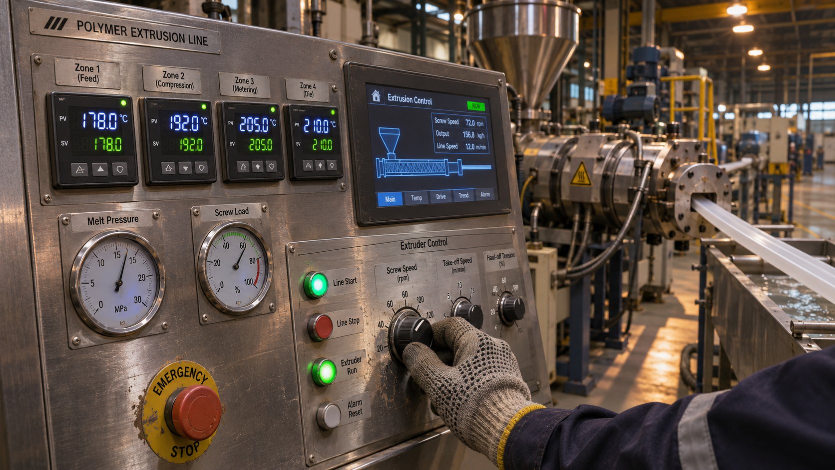
Die temperature deserves its own analysis because it operates through a different mechanism than bulk melt temperature. A cooler die lip creates a condensation surface: volatiles that are gaseous in the hot melt hit the relatively cooler metal and deposit as liquid or solid residue. Industry troubleshooting sources have noted that applying tempered warm air to the die exit area can continuously "clean" the lip by keeping it above the condensation threshold. Some operators use targeted heater bands around the die lip for the same purpose, maintaining a surface temperature high enough to prevent volatile deposition without overheating the polymer at the exit.
But there is a ceiling. An excessively hot die lip accelerates surface degradation of the polymer right at the exit point, creating a thin layer of degraded material that seeds new deposits. The sweet spot lies in matching the die lip temperature closely to the bulk melt temperature, minimizing the thermal differential that drives condensation while avoiding the excess heat that promotes degradation. In practice, this means die zone temperature should track within roughly 5 to 15 degrees of the melt temperature for most polyolefin applications, though the optimal differential varies by resin and die geometry.
Extrusion Rate, Shear Rate, and Residence Time
Speed introduces its own competing tradeoffs, and this is where operators often get trapped adjusting in the wrong direction.
Higher extrusion rates increase the shear rate at the die exit. As discussed in the mechanisms section, elevated shear promotes the fractionation effect that separates short polymer chains from the bulk melt and drives them toward the die wall. For resins susceptible to shear-induced drool — unimodal HDPE being the textbook example — pushing line speed higher can directly worsen accumulation. The Leoben research on HDPE blow molding confirmed that die drool build-up increased with throughput in several of the grades tested, consistent with a shear-driven fractionation mechanism.
At the same time, higher throughput reduces the residence time polymer spends at elevated temperatures inside the barrel and die. Less time at temperature means less thermal degradation, fewer volatile byproducts, and a smaller population of freshly generated low-molecular-weight fragments. For a resin where degradation is the dominant drool pathway — PP being the classic case — faster throughput can actually reduce buildup by limiting the thermal damage window.
The tradeoff could not be clearer:
| Adjustment | Effect on Shear-Driven Drool | Effect on Degradation-Driven Drool | Net Recommendation |
|---|---|---|---|
| Increase extrusion rate | Worsens (higher shear at die exit) | Improves (shorter residence time) | Helpful when degradation dominates; harmful when fractionation dominates |
| Decrease extrusion rate | Improves (lower shear at die exit) | Worsens (longer residence time, more thermal exposure) | Helpful when fractionation dominates; harmful when degradation dominates |
There is no single "correct" direction. The optimal adjustment depends entirely on diagnosing which root cause is at work. This is precisely why the internal-versus-external classification and the resin-by-resin susceptibility breakdown from earlier sections matter so much. Without knowing the dominant mechanism, an operator adjusting extrusion rate is essentially flipping a coin.
Pressure fluctuations add another layer. Pulsations from inconsistent screw feeding, non-optimal screw design, or too-narrow flow paths create momentary pressure spikes that can force fillers and low-molecular-weight material out of the polymer matrix at the die exit. Even if average process conditions look acceptable, periodic surging can drive intermittent drool events that appear random but are actually tied to upstream instability. Smoothing out these fluctuations through better screw design, consistent feeding, and adequate screen pack filtration addresses a root cause that temperature adjustments alone cannot touch.
The Role of Processing Aids in Die Drool Prevention
When material selection and process parameter optimization reach their practical limits, polymer processing aids (PPAs) offer a powerful additional tool. Traditionally, fluoropolymer-based PPAs have been the industry standard for reducing both melt fracture and die lip accumulation. These additives work by depositing a thin, low-friction fluoropolymer layer on the internal die surfaces. The coating reduces polymer adhesion to the metal, lowers the stress concentration at the die exit, and makes it physically harder for drool deposits to anchor and grow.
The mechanism is elegantly simple. During extrusion, the PPA migrates to the die wall — the same region where problematic polymer fractions tend to accumulate — and forms a dynamic, self-replenishing coating. This fluoropolymer layer reduces the wall shear stress that drives fractionation and creates a release surface that discourages both polymer and additive deposition. Industry evaluations confirm that effective PPAs address two critical processing problems simultaneously: eliminating melt fracture (sharkskin, orange peel) and reducing die lip buildup.
A few practical considerations temper the enthusiasm:
- PPA effectiveness varies by resin. Fluoropolymer PPAs perform exceptionally well in polyethylene blown film and cast film applications but may show different response curves in polypropylene, PVC, or engineering plastics. The die drool definition of success — whether measured as time between cleaning cycles, deposit weight, or product defect rate — depends on matching the right PPA chemistry to the specific polymer system.
- Startup conditioning time matters. PPAs do not coat the die instantly. A conditioning period of 15 to 60 minutes is typical before the fluoropolymer layer builds up sufficiently to provide full benefit. During this window, some drool may still form, and operators need to resist the temptation to conclude the additive is not working before it has had time to establish its coating.
- Interactions with other additives are real. Antiblock agents, slip additives, and certain pigments can interfere with PPA deposition or accelerate removal of the fluoropolymer coating from the die surface. When evaluating a PPA for your application, test it in the full formulation — not just the base resin — to ensure compatibility.
It is also worth noting a significant shift underway in PPA technology. Regulatory scrutiny of per- and polyfluoroalkyl substances (PFAS) has driven development of PFAS-free PPA alternatives that avoid fluoropolymer chemistry entirely. These newer formulations use alternative chemistries to provide similar melt fracture elimination and die buildup reduction. Early commercial results show promise, particularly in blown film and cast film, with ongoing evaluations extending to sheet extrusion and profile extrusion. For operations in food-contact packaging or jurisdictions with emerging PFAS restrictions, these alternatives represent a viable path forward — though performance testing in your specific application remains essential, as the PFAS-free PPA landscape is still maturing.
Taken together, temperature management, rate optimization, pressure stabilization, and processing aid selection form a comprehensive process-side toolkit. Each addresses a different piece of the die drool puzzle, and the most effective operations layer multiple strategies rather than relying on any single adjustment. Yet even a perfectly dialed-in process cannot overcome fundamental limitations in die hardware. The geometry of the die itself — land length, exit angle, surface finish — determines the flow conditions that either suppress or amplify every mechanism discussed so far.
Die Design Modifications and Surface Strategies for Drool Mitigation
The geometry of the die is where all the upstream variables — resin behavior, melt temperature, additive chemistry — finally meet metal. A die that amplifies shear gradients, creates stagnation pockets, or presents a rough surface at the lip will generate stubborn deposits regardless of how carefully you tune process parameters. Conversely, thoughtful design choices can suppress the die drool phenomenon at its physical origin, reducing cleaning frequency and extending uninterrupted production runs. The challenge is that practical guidance on die design for drool reduction is scattered across academic papers, equipment manufacturer bulletins, and tribal knowledge passed between tooling engineers. Here, we consolidate what works, what costs the most, and where each strategy delivers the biggest payoff.
Land Length, Lip Geometry, and Die Exit Angle Optimization
Die land length — the straight, parallel section of the flow channel just before the exit — has a direct and sometimes counterintuitive effect on buildup. Think of the land as the final stretch of highway before the off-ramp. What happens in this zone shapes the condition of the melt at the exact moment it leaves the die.
A shorter land reduces the contact time between the melt and the die wall. Less contact means less opportunity for low-molecular-weight species to migrate outward and accumulate at the lip. It also means less thermal exposure in the final zone, which can limit degradation-driven volatile generation. Industry sources confirm that increasing land length is sometimes recommended specifically to reduce the abruptness of pressure and velocity changes at the die exit, giving separated components less impetus to latch onto surfaces. Yet there is a tradeoff: longer lands increase the polymer's residence time in a confined channel, raising the risk of stagnation near the walls and thermal degradation of material sitting in low-flow zones. A longer land also increases pressure drop, which can raise the overall melt temperature through viscous heating.
The practical reality is that neither extreme works universally:
- Too short: Increases die swell, amplifies the abrupt pressure release that promotes component separation, and may worsen shear-induced fractionation at the exit.
- Too long: Creates stagnation zones where polymer degrades and adheres to internal walls, feeds internal deposits, and increases pressure drop and viscous heating.
Die exit angle plays a complementary role. A sharp, square-edged die lip creates an abrupt transition from constrained flow to free surface, maximizing the stress discontinuity that promotes drool formation. A slightly chamfered or radiused exit edge can smooth that transition, reducing the stress concentration where low-molecular-weight species tend to separate from the bulk melt. Even a small modification — rounding the outer lip edge to a radius of 0.1 to 0.3 mm — can noticeably reduce deposit anchoring without significantly altering the extrudate profile.
Lip gap uniformity matters as well. An uneven gap creates localized velocity differences, and the slower-flow zones become preferential deposition sites. Regular measurement of the die gap during maintenance helps catch wear-induced asymmetry before it translates into uneven buildup patterns across the die face.
Surface Coatings and Treatments for Drool Reduction
Even with optimized geometry, the die lip surface itself can either resist or invite deposits. The principle is straightforward: lower surface energy means weaker adhesion for polymer residue, additives, and condensed volatiles. Several coating and treatment options target this principle, each with different cost, durability, and effectiveness profiles.
Chrome plating has long been a standard surface treatment for extrusion dies. Research published in Tribology International demonstrated that chrome-plated surfaces reduced the coefficient of friction by 20% and the wear rate by 80% compared to untreated metal, while also improving the bonding of transfer films by 20%. The elevated hardness of the chrome layer distributes load more uniformly, and the characteristic microcracks in chrome plating actually help retain debris and reduce direct polymer-to-metal contact. For die drool applications, chrome plating provides a harder, smoother surface that resists both abrasion — critical when running glass-filled compounds — and deposit anchoring.
PTFE coatings take surface energy reduction further. Polytetrafluoroethylene has one of the lowest surface energies of any solid material, making it exceptionally difficult for polymer deposits to bond. Applied as a thin coating on die lip surfaces, PTFE dramatically reduces the adhesion force between drool deposits and the die face. The limitation is durability: PTFE coatings are softer than chrome and wear faster under abrasive conditions, requiring periodic reapplication.
Fluoropolymer surface treatments and proprietary low-friction coatings offer a middle ground between chrome hardness and PTFE release properties. Some modern die coating systems combine a hard base layer with a fluoropolymer topcoat, delivering both wear resistance and low surface energy. These multi-layer treatments are gaining traction in high-volume film and sheet extrusion operations where die cleaning downtime is especially costly.
The following list ranks die design modification strategies by implementation difficulty and expected drool reduction impact, from easiest to most capital-intensive:
- Polish and re-finish the existing die lip surface — Low cost, immediate impact. Removes micro-roughness that anchors deposits. Should be part of every scheduled die maintenance.
- Apply PTFE or fluoropolymer spray coating to the die lip — Moderate cost, fast turnaround. Significant reduction in deposit adhesion, though reapplication is needed periodically.
- Chrome plate die lip and land surfaces — Moderate cost, longer lead time. Provides durable hardness and friction reduction. Especially valuable for glass-filled or abrasive compounds.
- Chamfer or radius the die exit edge — Low to moderate cost if done during scheduled maintenance. Reduces the stress discontinuity that promotes component separation at the exit.
- Optimize die land length for the specific resin and application — Moderate to high cost, requires die modification or replacement. Delivers fundamental improvement but demands careful engineering analysis to avoid introducing new problems.
- Redesign die flow channels to eliminate stagnation zones — High cost, significant lead time. The most effective solution for internal deposits but requires computational flow analysis and custom tooling.
- Install multi-layer hard-coat plus fluoropolymer die surface systems — High cost. Best suited for high-volume lines where extended run times between cleanings justify the investment.
A critical caution: die modifications are capital-intensive and sometimes irreversible. Shortening a die land or changing an exit angle without first confirming the dominant drool mechanism can introduce new problems — increased die swell, melt fracture, or dimensional instability — while failing to address the original issue. The systematic diagnostic approach described later in this article should always precede hardware changes. Evidence first, then engineering.
Application-Specific Die Challenges
Die geometry, gap size, and ambient air exposure vary dramatically across extrusion applications, and these differences shift which drool mechanism dominates and which design strategies deliver the most value.
Blown film dies feature annular gaps with relatively large exposed lip circumferences. The entire die exit ring is exposed to ambient air, creating a continuous condensation surface for volatiles. Die drool is more common in polypropylene than polyethylene extrusion in blown film applications, partly because PP's higher volatile generation rate feeds deposits around the full annular lip. Cleaning access is limited during operation, making surface coatings and PPAs especially valuable since they extend the interval between manual interventions.
Cast film dies present a wide, flat lip where buildup tends to concentrate at the edges and any slight imperfections in lip uniformity. The open exposure of the melt curtain to air immediately after the die exit accelerates oxidative skinning that can seed deposit formation. Maintaining tight lip gap tolerances and uniform die temperature across the full width are critical.
Pipe extrusion involves annular dies similar to blown film but with much larger gap dimensions and lower shear rates. The lower shear reduces fractionation-driven drool, but longer residence times in the die land increase the risk of degradation-driven deposits, particularly with PP pipe compounds. Internal stagnation zones at spider legs or mandrel supports are common sources of internal deposits.
Profile extrusion introduces the most complex geometries. Irregular cross-sections create uneven flow velocities across the die, with slow-moving zones at thin sections and corners acting as natural stagnation points. These dead spots are prime locations for internal deposit formation. Profile die design must balance flow uniformity with drool prevention, often requiring iterative adjustments guided by production trials.
Wire and cable coating represents a unique case. The die gap is extremely small, shear rates are high, and line speeds can reach 50 to 200 meters per minute. Pressure stability is paramount because any variation encodes directly into coating thickness. Die drool is more severe in polypropylene than polyethylene in these applications due to PP's sensitivity to the high shear environment, and crosslinkable polyolefin compounds add the risk of scorch-related internal deposits. Tight closed-loop pressure control and frequent die inspection are standard practice.
Sheet extrusion uses wide flat dies with adjustable lip bolts. The adjustability is a double-edged sword: it allows fine-tuning of sheet thickness uniformity but creates potential micro-gaps and surface irregularities at each bolt location where deposits can anchor. Regular die lip cleaning and bolt adjustment are essential to prevent localized buildup from translating into sheet gauge variation.
Across all these applications, a consistent theme emerges: the die is not a passive component. Its geometry, surface condition, and thermal profile actively participate in either suppressing or amplifying every drool mechanism. Optimizing these hardware factors delivers compounding benefits alongside the material and process adjustments covered in earlier sections. Yet hardware is only as effective as the diagnostic logic guiding it — applying the right fix requires first identifying the right root cause across all three domains: material, process, and equipment.

Systematic Diagnostic Troubleshooting for Die Drool Problems
You have the resin-by-resin susceptibility data. You understand how temperature, shear, and residence time compete with each other. You know how die geometry and surface condition either amplify or suppress deposits. The missing piece? A structured method for pulling all of that knowledge together on the production floor, where the deposit is growing and the clock is ticking. Most operators default to a single fix — scrape the lip, bump the temperature, add a processing aid — and hope for the best. That approach treats symptoms, not causes, and the buildup returns within hours. What you need instead is a diagnostic framework that narrows the root cause before you touch a single setting.
A Three-Pillar Diagnostic Framework
Every die drool problem traces back to one of three domains: the material running through the extruder, the process conditions applied to it, or the equipment shaping and delivering it. These three pillars overlap in practice, but separating them during diagnosis prevents the common mistake of chasing the wrong variable. Think of it like a medical triage: you would not prescribe medication before determining whether the problem is circulatory, respiratory, or structural.
The following step-by-step sequence walks you through the diagnostic logic from initial observation to targeted corrective action. Follow it in order; skipping steps is what leads to wasted trials and repeated failures.
- Classify the deposit as internal or external. Inspect the die face during operation. If visible accumulation is growing on the outside lip surface, you are dealing with external drool. If the die face looks relatively clean but the extrudate shows persistent die lines, continuous surface roughness, or dimensional drift, suspect internal deposits. A die teardown during the next scheduled maintenance confirms internal buildup. This classification determines which corrective actions are even relevant.
- Characterize the deposit itself. Is it oily and discolored (suggesting degradation volatiles)? Waxy and light-colored (pointing to low-molecular-weight fractionation or additive bloom)? Dry and abrasive (indicating filler migration)? Sticky and stretchy when warm (polymer-rich material)? The physical character of the deposit is a direct clue to the dominant formation mechanism. LSZH extrusion troubleshooting protocols recommend comparing deposit ash content and thermal behavior against the original compound to distinguish polymer degradation from filler-rich or lubricant-rich residues.
- Check the distribution pattern. Even buildup around the entire die lip suggests a material or thermal condition affecting the complete melt stream. Buildup concentrated at one position points to localized die damage, alignment issues, or cooling imbalance. Buildup that correlates with pressure pulsations implicates upstream feeding or screw performance problems. The pattern tells you where to look next.
- Evaluate material-related causes first. Has the resin lot changed recently? Compare the current lot against a retained reference sample using identical process settings. Record torque and head pressure after the line reaches thermal stability. A sustained change of approximately 5% or more in either parameter at equal operating conditions warrants investigation. Check moisture content, pellet appearance, filler dispersion, and additive loading. Inspect for material separation in the hopper, feed throat, and conveying system. Fine mineral particles and low-molecular-weight additives can migrate during storage or transport, delivering a feed composition different from the nominal formulation.
- Isolate process-related causes second. Measure actual melt temperature with a calibrated instrument rather than relying solely on barrel zone setpoints. Compare current melt temperature, die zone temperatures, screw speed, throughput, and head pressure against the documented baseline from a stable production run. Adjust one variable at a time and allow sufficient residence time for the new condition to propagate to the die. Use the competing-effects logic from the process parameters discussion: if buildup increases with screw speed at constant output, shear heating or insufficient melting may be involved; if it increases with output but not speed, the restriction is likely in the die, screen pack, or flow channel; if it appears after a long hold at low output, residence time and thermal degradation are the prime suspects.
- Investigate equipment-related causes third. This is where many troubleshooting efforts fall short. Inspect the die for scratches, worn coating, carbonized residue, dead spots, and dimensional changes against the original drawing. Check die alignment, tip position, and concentricity. Examine the breaker plate, screen pack, and adapter for restrictions or degraded material. Then look upstream: assess screw flight diameters, barrel bore dimensions, and wear patterns. Worn screws and barrels alter melt homogeneity, increase residence time in dead zones, and fail to maintain proper melt temperature, all of which worsen deposits even when the die itself is in good condition.
- Cross-reference findings and prioritize corrective actions. Many real-world cases involve overlapping causes. A slightly degraded resin lot running through a worn screw barrel at marginally high melt temperature may produce drool that no single-variable fix eliminates. Prioritize corrections by impact and implementation speed: material verification and process adjustment are fast and low-cost; die cleaning and surface treatment are moderate; die redesign and screw-barrel replacement are slower but address fundamental root causes.
This sequence is deliberate. Material checks come first because they are the fastest to execute and the most commonly overlooked. Process adjustments come second because they are reversible and can be tested within a single production run. Equipment evaluation comes last not because it is least important, but because it requires downtime and should be guided by evidence gathered in the earlier steps rather than guesswork.
Connecting Die Drool to Product Quality Defects
Here is where diagnosis becomes truly practical. The defects that show up on your finished product are not random — they carry signatures that point back to specific drool types and root causes. An experienced operator reads these patterns the way a mechanic reads engine sounds. Surface streaks tell one story; intermittent contamination spots tell another; and persistent dimensional drift tells yet a third.
In film extrusion, die lip drool that breaks free creates intermittent gels or hard spots embedded in the web, often visible only when the film is stretched or held against light. These events appear random but actually correlate with buildup mass reaching a critical threshold. In pipe extrusion, internal deposits along spider legs or mandrel supports produce continuous longitudinal weld lines that weaken the pipe wall at predictable locations. Profile extrusion sees localized surface roughness at corners and thin-wall sections where stagnation zones trap degraded material. Wire and cable coating operations experience sudden jacket thickness variation when accumulated material dislodges and temporarily alters the die gap.
The following table maps common defect types to their likely drool mechanism and the most effective corrective action. Use it as a diagnostic shortcut when a quality issue emerges on your line:
| Defect Type | Extrusion Process | Likely Die Drool Mechanism | Recommended Corrective Action |
|---|---|---|---|
| Intermittent gels or hard contamination spots | Blown film, cast film | External buildup breaking free from the die lip (polymer degradation, additive bloom) | Reduce melt temperature, apply fluoropolymer PPA, polish die lip surface, shorten cleaning intervals |
| Continuous die lines or streaks | Film, sheet, profile | Internal deposits or die lip surface damage creating drag marks on the extrudate | Inspect and clean internal die land channels, re-polish or re-coat the die lip, check for die wear or scratches |
| Discolored specks or brown/black particles | All processes | Thermally degraded polymer from stagnation zones or excessive residence time detaching from internal surfaces | Eliminate dead zones in die geometry, reduce melt temperature, purge the system, inspect screw and barrel for wear increasing residence time |
| Waxy or oily surface haze | Film, sheet | Additive bloom or volatile condensation at the die exit | Adjust additive package with resin supplier, raise die lip temperature to reduce condensation, improve ventilation at die exit |
| Dimensional variation (wall thickness drift, diameter shift) | Pipe, wire coating, tubing | Deposit accumulation altering the effective die gap; pressure instability from upstream equipment | Clean die and measure gap against drawing, stabilize pressure by inspecting feed system, screen pack, and screw-barrel clearance |
| Weld line weakness or visible knit lines | Pipe, profile (spider-type dies) | Internal deposits at spider legs or flow dividers disrupting melt reconvergence | Redesign flow channel to minimize stagnation at spider supports, reduce residence time, schedule more frequent die teardowns |
| Periodic surface bumps or lumps | Profile, wire coating | Pressure pulsations from inconsistent feeding or worn screw-barrel assembly, forcing filler or low-MW material to the die lip intermittently | Check feed stability, inspect screw flights and barrel bore for wear, evaluate screen pack condition, smooth upstream pressure fluctuations |
Notice the last row in that table. Periodic surface bumps that seem to defy explanation are a classic indicator of equipment-related causes upstream of the die itself. Pressure differences and pulsations from non-optimal screw design repeatedly disturb the melt at the die exit, accelerating die lip drool and creating intermittent defects that operators may attribute to material inconsistency or random process drift. Worn screws and barrels compound the problem by widening flight clearances, reducing shear input, creating dead zones in the metering section, and producing a less thermally homogeneous melt. All of these effects cascade forward to the die, manifesting as deposits and defects that no die-focused fix can fully resolve.
This is the most frequently overlooked category in die drool troubleshooting. Equipment wear is gradual, invisible without measurement, and easy to rationalize away. A screw that has lost a few tenths of a millimeter on its flight diameter does not trigger an alarm. But that small dimensional change alters plasticizing performance in ways that directly feed every drool mechanism discussed throughout this article — higher effective residence time, inconsistent melt temperatures, pressure instability, and reduced homogeneity. The three-pillar framework exists precisely to ensure that this upstream equipment dimension is never skipped during diagnosis.
When diagnostic evidence consistently points back to melt quality issues that process adjustments alone cannot correct, the next logical question becomes: how do you assess whether screw and barrel condition has crossed the threshold from acceptable wear into an active contributor to your die drool problem?
Upstream Screw and Barrel Wear as a Hidden Die Drool Contributor
Here is a scenario that plays out in extrusion plants far more often than anyone admits. A process engineer spends weeks optimizing melt temperature, adjusting line speed, polishing the die lip, and even switching resin grades — yet the buildup keeps returning. The die itself checks out clean during teardowns. The additive package is balanced. The melt temperature readings look reasonable. So what is left? The answer frequently sits several feet upstream from the die, inside the barrel, where a gradually worn screw has been quietly degrading melt quality for months.
How Screw and Barrel Wear Affects Melt Quality at the Die
Worn screws and barrels do not announce themselves with a single dramatic failure. The degradation is slow, incremental, and easy to rationalize away. But the cumulative effect on the melt reaching the die is significant — and it feeds every die drool mechanism covered in this article.
When the radial clearance between the screw flight outer diameter and the barrel inner wall increases, leakage flow becomes inevitable. Polymer that should be conveyed forward instead slips backward over the flights, getting sheared repeatedly without advancing toward the die. This creates several cascading problems:
- Reduced shear input to the bulk melt. Wider clearances mean less efficient plasticizing. The melt delivered to the die is less homogeneous — pockets of undertreated material mix with zones that have been overworked — creating the kind of thermal and compositional inconsistency that promotes additive bloom and localized degradation at the die exit.
- Increased effective residence time. Material cycling over worn flights spends longer inside the barrel at elevated temperatures. For degradation-sensitive resins like polypropylene, this extended thermal exposure generates additional low-molecular-weight fragments and volatiles that feed external deposits at the die lip.
- Higher melt temperatures from compensatory speed increases. As output drops due to leakage flow, operators typically increase screw speed to maintain production targets. That higher rpm drives up shear heating, raising the actual melt temperature above what the barrel zone setpoints suggest. The result? More thermal degradation, more volatile generation, and worse die drool — even though the temperature controller displays the same numbers as before.
- Pressure instability and surging. Worn metering sections cannot maintain consistent pumping pressure. The resulting fluctuations propagate forward to the die, creating the intermittent pressure spikes that force filler particles and low-molecular-weight species out of the polymer matrix at the exit. Pressure pulsations from non-optimal screw performance are listed among the top causes of die drool formation, yet the connection to upstream wear is rarely made explicit on the production floor.
Root wear compounds the problem further. As the screw root surface erodes, particularly on the forwarding side of the flights in high-pressure zones, pockets form where material hangs up and degrades. Industry analysis confirms that root wear creates stagnation points that produce discolored specks, surging, and contaminated extrudate — all symptoms that operators may misattribute to die condition or resin quality rather than tracing back to the screw itself.
Mixing sections and barrier flights are similarly vulnerable. As dispersive mixing elements wear, they lose the tight clearances needed to impart uniform shear across the melt cross-section. The result is a less isothermal, less homogeneous melt arriving at the die — a direct precursor to the localized fractionation and additive separation that drive both internal and external deposits.
The critical point is this: an operator focused solely on the die will never find these upstream root causes. The die may be in perfect condition, the process parameters may look textbook-correct on screen, and the resin may be within specification. But if the screw and barrel are delivering a degraded, inconsistent melt, die drool will persist no matter what happens at the die face.
Evaluating Component Condition Through Dimensional Inspection
Imagine trying to diagnose an engine problem without ever checking the pistons and cylinders. That is essentially what happens when extrusion plants troubleshoot die drool without measuring their screw and barrel dimensions. The inspection process is straightforward, but it requires intentional scheduling because it demands pulling the screw — something many plants avoid until a crisis forces the issue.
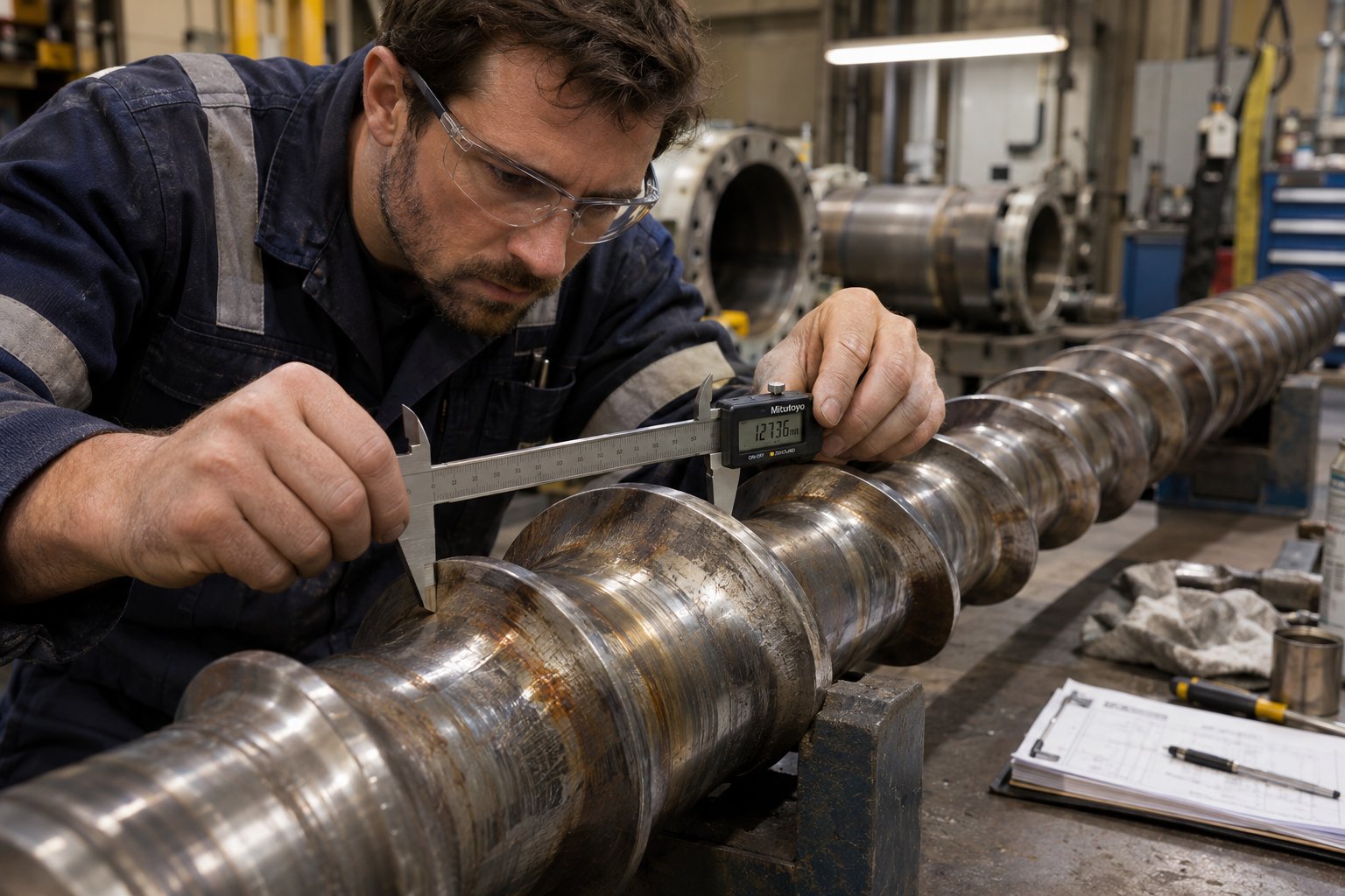
A proper dimensional assessment involves measuring screw flight outer diameters at multiple points along the length, recording barrel bore dimensions at corresponding locations, and comparing both sets of measurements against the original equipment manufacturer specifications. Wear patterns reveal the story: heavy flight OD wear in the transition and metering sections confirms the high-pressure abrasion mechanism. Localized root erosion on the forwarding side of flights indicates material hang-up zones. Barrel bore enlargement at specific locations points to corrosive or abrasive attack from the resin or filler system.
A common industry rule of thumb considers a flight clearance four times the original tolerance as the threshold for screw replacement, though resin viscosity matters: a high-viscosity polyethylene tolerates more clearance than a lower-viscosity polypropylene before output loss and melt quality degradation become significant. Rather than relying solely on rules of thumb, calculating the estimated rate loss based on actual clearance, flight geometry, head pressure, and melt viscosity provides a far more accurate picture of whether wear has crossed a meaningful threshold.
The following indicators suggest that screw or barrel wear is actively contributing to your die drool problem — not just reducing output or raising energy costs, but specifically worsening deposits at the die:
- Die drool severity has gradually increased over months or years without any change in resin grade, additive package, or die condition
- Melt temperature measured at the die is consistently higher than barrel zone setpoints, even after recalibrating thermocouples
- Screw speed has been incrementally increased over time to maintain the same output rate
- Pressure readings at the die show increased variability or periodic surging that does not correlate with feed rate or resin changes
- Product defects include discolored specks or black particles alongside die lip buildup, suggesting internal degradation upstream of the die
- Switching to a lower-viscosity resin grade results in disproportionately worse buildup, indicating that leakage flow over worn flights is amplified with less viscous melts
- Purging the system temporarily improves surface quality, but deposits return faster than historical norms — consistent with degraded material continuously generated in worn root zones and flight clearances
When several of these indicators appear simultaneously, measuring the screw and barrel is no longer optional — it is the diagnostic step most likely to reveal the true root cause.
Companies like NANHAIYA offer component-focused evaluation for both single-screw and twin-screw extruders, reviewing machine information, drawings, photos, and measured dimensions to assess whether custom or replacement screw barrels are the right path for an existing production line. This kind of specialist assessment is particularly valuable when in-house maintenance teams lack the baseline data or tooling history needed to judge whether current wear levels are within acceptable limits or have crossed into performance-degrading territory.
A necessary caveat, though: replacing a worn screw and barrel addresses the upstream melt-quality issues that amplify die drool, but it is not a guaranteed cure for every surface defect. A new screw paired with a poorly designed die geometry still produces stagnation zones. A fresh barrel running an inherently drool-prone resin grade still requires proper temperature management and potentially a processing aid. The three-pillar diagnostic framework — material, process, equipment — exists precisely because no single intervention covers all the root causes. Screw and barrel replacement is one powerful element in a broader strategy, not a standalone silver bullet.
What separates plants that chronically fight die drool from those that rarely encounter it is not a single piece of better equipment or a secret resin grade. It is the shift from reactive fixes — scraping the lip, bumping a temperature, swapping a resin lot — to proactive management that prevents buildup before it starts. That shift requires scheduled protocols, disciplined maintenance routines, and a fundamentally different relationship with equipment inspection.
Preventive Maintenance and Proactive Die Drool Management
Scraping the die lip every few hours, adjusting temperatures on the fly, and running until defects appear on finished product — that is the reactive cycle most extrusion plants live in. It works, barely, until it does not. A contaminated roll ships to a customer. A surprise die teardown kills half a shift. A persistent quality complaint triggers a root cause investigation that should have happened months earlier. The plants that rarely deal with chronic buildup are not lucky. They operate on structured preventive protocols that address the deposit before it ever reaches the extrudate. Shifting from firefighting to prevention costs less, produces less scrap, and delivers the kind of consistency that reactive troubleshooting simply cannot match.
Scheduled Die Cleaning Protocols and Best Practices
How often should you clean the die lip? The honest answer is: it depends on your resin, your die, and your quality tolerance. But leaving it to operator judgment without a baseline frequency is how cleaning gets deferred until the deposit has already contaminated product. A better approach establishes a cleaning interval based on historical buildup rates and then adjusts that interval as conditions change.
Start by documenting how quickly visible accumulation forms under stable production conditions. If you are running polypropylene and external deposits reach a critical mass within four hours, your baseline cleaning interval should be set well inside that window — every two to three hours, for example. For a bimodal HDPE grade that barely shows buildup over an eight-hour shift, a once-per-shift cleaning may be more than adequate. The point is to base the schedule on evidence from your specific line, not on a generic recommendation from a resin bulletin.
Tool selection during cleaning matters more than most operators realize. Aggressive scraping with hardened steel tools can scratch the die lip surface, creating micro-roughness that anchors future deposits even more firmly. That seemingly thorough cleaning actually makes the next buildup cycle worse. Brass scrapers are the standard recommendation for manual lip cleaning because brass is softer than tool steel and will not gouge a hardened die surface. Dedicated die-lip cleaning knives with polished edges provide even more control.
For offline maintenance, two additional methods extend the toolkit:
- Chemical purge compounds — These engineered materials are designed to scour internal flow channels and die surfaces during material transitions or planned shutdowns. They work by combining mechanical scrubbing action with chemical affinity for degraded polymer residue. Effective purging reduces the seed layer of carbonized material that accelerates future deposit formation. Davis-Standard's maintenance guidance recommends purging at 75 to 100 percent of normal run speed for maximum scrubbing effectiveness before reducing speed for shutdown.
- Ultrasonic cleaning — For dies removed during scheduled maintenance, ultrasonic baths dissolve and dislodge deposits from internal channels, land surfaces, and tight geometries that manual tools cannot reach. This method is especially valuable for complex profile dies and multi-layer coextrusion dies where internal stagnation zones harbor deposits invisible from the outside.
One risk deserves emphasis: aggressive cleaning of coated die surfaces — PTFE, fluoropolymer, or chrome-plated lips — can damage the protective layer and actually increase future drool susceptibility. Always match the cleaning method to the surface treatment. Brass scrapers are safe on chrome; they can damage softer fluoropolymer coatings. Chemical purge compounds should be verified for compatibility with any die coating before use. When in doubt, consult the die manufacturer's maintenance instructions for the specific coating system installed.
Startup, Shutdown, and Transition Procedures That Minimize Drool
Some of the worst die drool problems are not caused by steady-state production conditions at all. They are seeded during startups, shutdowns, and material transitions — the moments when polymer sits stagnant in the barrel and die at elevated temperatures, degrading quietly while operators attend to other tasks.
Think about what happens during an uncontrolled shutdown. The extruder stops, but the heaters stay on. Polymer trapped in stagnation zones, dead spots behind screen packs, and the die land continues cooking. Over hours or overnight, that stagnant material degrades into exactly the kind of low-molecular-weight, carbonized residue that seeds aggressive deposit formation on the next startup. When the line restarts, this degraded material mixes into the fresh melt and migrates to the die lip, creating immediate buildup that would not have occurred if the shutdown had been managed properly.
A controlled shutdown protocol addresses this directly. The Davis-Standard procedure for blown film lines provides an instructive template: reduce screw speed toward the end of the run, lower barrel temperatures progressively (to 325 degrees Fahrenheit for PE or 375 degrees Fahrenheit for PP), introduce a thermally stable purge blend with antioxidant, and shut down at approximately 25 to 40 percent of normal output. Critically, the procedure calls for leaving a small pool of purge material over the die lip to prevent oxygen from reaching the die land — a simple step that blocks oxidative degradation of residual polymer sitting in the most drool-sensitive zone of the entire system.
Restart procedures carry their own risks. Bringing the line up to full operating temperature too quickly exposes stagnant polymer to heat before it can be purged out. The recommended approach is to heat-soak the system at a temperature lower than normal operating conditions, ensuring the polymer is fully molten before turning the screw. A lower startup temperature serves two purposes: it reduces thermal exposure of the stagnant material, and it maintains a higher polymer viscosity that creates better scrubbing forces against flow surfaces during the initial purge. Only after the purge runs clean should production temperatures be set and the line brought to full speed.
Material transitions deserve equal discipline. Switching from a high-drool-risk resin like polypropylene to a lower-risk polyethylene grade without adequate purging leaves PP degradation products clinging to internal surfaces. Those residues then contaminate the incoming PE, creating drool that the operator blames on the new resin when the real cause is leftover material from the previous run. A proper transition includes a dedicated purge cycle between resins, with sufficient time and material volume to displace the old formulation from every flow path — including dead spots behind breaker plates, screen packs, and die manifold channels.
Building a Proactive Component Maintenance Schedule
Die cleaning and proper startup procedures address the immediate deposit-forming surfaces. But proactive die drool management extends well beyond the die itself. The upstream components — screws, barrels, breaker plates, screen packs, adapters — all influence the quality of the melt arriving at the die exit. Letting any of these components drift out of specification quietly undermines every other preventive effort.
The following checklist presents a recommended preventive maintenance program specifically designed to minimize die drool risk across the entire extrusion system. It is organized by frequency and component, with each item tied to the drool mechanism it addresses:
- Every shift: Visually inspect the die lip for accumulation. Record buildup thickness or appearance as a trend metric. Clean using brass scrapers or approved tools if deposits approach the threshold established for your resin and quality tolerance. Log cleaning times to track whether intervals are shortening — a leading indicator that something upstream has changed.
- Every material transition: Execute a full purge protocol before introducing the new resin. Verify purge completeness by inspecting the extrudate for discoloration, specks, or off-specification appearance. Do not assume the system is clean based on time alone; visual confirmation matters.
- Weekly: Inspect the die and adapter joint for leakage, check die bolt torque (thermal cycling loosens bolts), and verify die zone heater operation. Record melt pressure at a fixed screw speed and compare against the baseline. A rising trend at constant conditions may indicate screen pack loading, die restriction from internal deposits, or barrel wear reducing pumping efficiency.
- Monthly: Measure and record melt temperature at the die using an independent probe — not just the barrel zone display. Compare actual melt temperature against the setpoint profile. A growing gap suggests barrel heater degradation, thermocouple drift, or increased shear heating from worn components. Inspect the screen pack and breaker plate for degraded material accumulation or flow restriction.
- Quarterly: Schedule a die teardown for internal inspection. Document the location, thickness, and character of any internal deposits. Photograph the die land and flow channel surfaces for comparison against previous inspections. Re-polish the die lip and land surfaces if buildup or micro-scratching is detected. Verify die gap dimensions against the original drawing.
- Semi-annually: Perform a dimensional inspection of the screw and barrel. Measure screw flight outer diameters at feed, transition, and metering sections. Measure barrel bore at corresponding locations. Compare against original equipment specifications. Calculate flight-to-barrel clearance and track the wear trend over successive inspections. This is the single most important step for detecting the gradual upstream melt-quality degradation that silently amplifies die drool over months and years.
- Annually or at major maintenance shutdowns: Evaluate the overall condition of the screw root surfaces, mixing sections, and barrier flights for erosion, corrosion, or material hang-up zones. Inspect feed throat condition and cooling circuit integrity. Review the full maintenance log for recurring patterns — are cleaning intervals getting shorter? Is melt pressure trending upward? Are defect types shifting? These trends inform whether component replacement, die modification, or formulation adjustment should be prioritized for the coming production period.
That semi-annual screw and barrel inspection deserves particular emphasis. Many plants skip it because pulling the screw requires downtime, and if the line is still producing acceptable output, the urgency feels low. But as the previous chapter detailed, worn components degrade melt quality in ways that manifest as die drool long before output loss becomes obvious. Dimensional inspection at planned intervals — potentially with support from specialists such as NANHAIYA, who evaluate wear through machine information, drawings, and measured dimensions for both single-screw and twin-screw extruders — helps plants catch degradation before it shows up as deposits, defects, or customer complaints. Identifying whether a custom or replacement screw barrel is warranted based on actual measured clearances is far more cost-effective than running worn components until quality failures force an emergency replacement.
An important caveat applies here, just as it did in the equipment discussion earlier: screw and barrel replacement is one element of a broader preventive program, not a standalone solution for all die-related surface defects. A brand-new screw installed into a system with a poorly designed die, an unsuitable resin grade, or incorrect process temperatures will not eliminate buildup on its own. The three-pillar framework — material, process, equipment — runs through every level of this maintenance strategy. Each checklist item addresses a specific pillar, and the program works because all three pillars are covered systematically rather than in isolation.
Plants that commit to this kind of structured prevention consistently report longer run times between die cleanings, fewer scrap events from deposit contamination, and more predictable product quality across shifts and operators. The investment is not exotic equipment or proprietary technology. It is discipline: scheduled inspections, documented baselines, trend tracking, and the willingness to act on leading indicators before they become production-stopping problems. Die drool will always be part of polymer extrusion — but with proactive management, it becomes a controlled variable rather than a recurring crisis.
Frequently Asked Questions About Die Drool in Extrusion
1. What causes die drool in polymer extrusion?
Die drool results from three overlapping mechanisms. First, low-molecular-weight polymer chains migrate toward the die wall under shear and slowly accumulate at the lip. Second, additives such as slip agents and antioxidants bloom to the melt surface and condense on the cooler die exit. Third, thermal and oxidative degradation breaks polymer chains, generating volatile byproducts that deposit at the die face. The relative contribution of each mechanism depends on the resin type, additive package, melt temperature, residence time, and die geometry. Polypropylene is especially vulnerable because it degrades through beta-scission, continuously producing mobile short-chain fragments. In HDPE, shear-induced molecular weight fractionation is often the dominant pathway. Identifying which mechanism drives your specific buildup is essential before selecting a corrective action.
2. How do you prevent die drool buildup during extrusion?
Prevention requires a layered approach across material, process, and equipment. On the material side, selecting resin grades with bimodal molecular weight distributions or long-chain branching reduces the population of mobile low-MW species that feed deposits. Fluoropolymer-based polymer processing aids (PPAs) coat internal die surfaces with a low-friction layer that discourages adhesion. Process-side adjustments include tightening melt temperature control, matching die lip temperature closely to bulk melt temperature to avoid volatile condensation, and stabilizing extrusion pressure to prevent surging. Equipment maintenance plays an equally important role: polishing die lip surfaces, applying chrome or PTFE coatings, eliminating internal stagnation zones, and inspecting screws and barrels for wear that degrades melt quality upstream of the die.
3. What is the difference between internal and external die drool?
External die drool is the visible accumulation on the outside face of the die lip, caused primarily by low-MW species migration, additive blooming, and volatile condensation. It produces intermittent contamination spots or gels when deposits break free and embed in the extrudate. Internal die drool forms inside the die land or flow channel, typically in stagnation zones or areas with poor geometry where polymer degrades and adheres to metal surfaces. Internal deposits cause persistent die lines, continuous surface roughness, and dimensional variation rather than intermittent defects. The distinction matters because corrective actions differ significantly: PPAs and temperature adjustments target external deposits, while die geometry redesign and internal channel polishing address internal buildup.
4. Why is die drool more common in polypropylene than polyethylene extrusion?
Three factors make polypropylene inherently more drool-prone. First, PP has a narrower processing window with less margin between its melting point and degradation onset temperature, making thermal chain scission more likely during normal processing. Second, PP degrades through beta-scission rather than crosslinking, meaning every degradation event creates shorter, more mobile chain fragments that migrate to the die lip. Third, polypropylene formulations typically carry heavier additive packages, including slip agents and clarifiers, which are more susceptible to blooming and condensation at the die exit. By contrast, polyethylene, especially bimodal HDPE and LDPE with long-chain branching, resists the shear-induced fractionation mechanism and tolerates a wider temperature range before significant degradation occurs.
5. Can worn screws and barrels cause die drool problems?
Yes, and this is one of the most frequently overlooked root causes. Worn screws and barrels increase flight-to-barrel clearance, which allows leakage flow that extends effective residence time, reduces plasticizing efficiency, and produces a less homogeneous melt. Operators often compensate by raising screw speed, which increases shear heating and actual melt temperature beyond setpoints. The resulting melt delivers more low-MW degradation products, more volatile byproducts, and greater pressure instability to the die, all of which amplify deposit formation. Companies such as NANHAIYA (nhyscrews.com) offer dimensional evaluation services for single-screw and twin-screw extruders, reviewing machine data and measured dimensions to determine whether replacement components are warranted. However, screw-barrel replacement addresses upstream melt quality and should be combined with proper die maintenance and process optimization for complete drool management.
Written by
Nanhaiya Technical Team
Zhoushan Nanhaiya Plastic Machinery Co., Ltd.
The Nanhaiya technical team supports screw and barrel manufacturing projects through application review, technical communication, custom manufacturing coordination, and production and quality control.
Discuss Your Application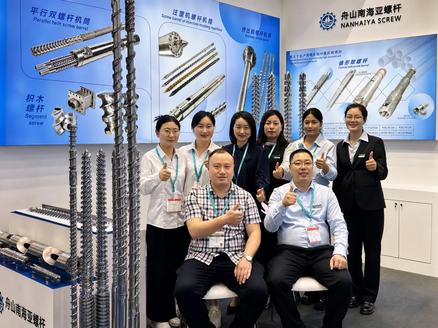
Related Articles
More insights on screw barrel technology and plastics processing.
Injection Molding Color Mixing: From Streaks to Flawless Consistency
Nov 19, 2026
Master injection molding color mixing with expert guidance on colorant types, screw design, process parameters, defect troubleshooting, and Delta E QC protocols.
Read Article
Wrong Extruder Breaker Plate? Spot the Signs Before Scrap Piles Up
Nov 19, 2026
Learn how to select, size, and maintain your extruder breaker plate. Covers hole geometry, pressure drop, polymer-specific specs, and troubleshooting tips.
Read Article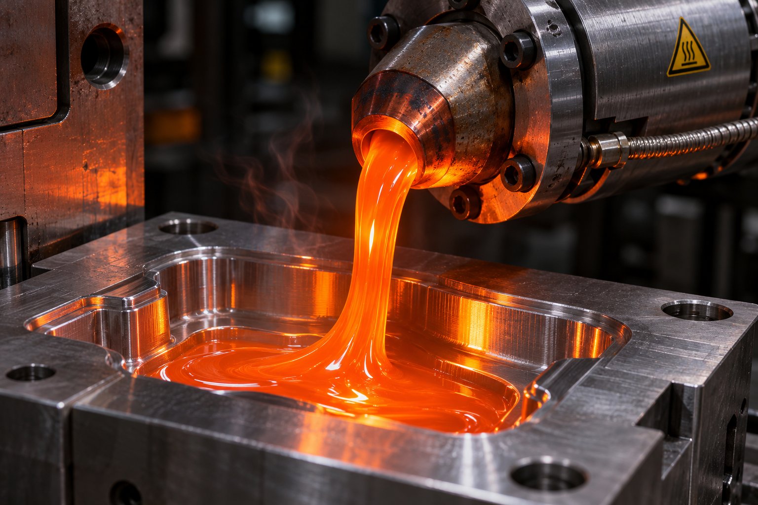
Injection Molding Melt Temperature: Why Your Barrel Settings Lie
Nov 19, 2026
Learn why barrel set points lie about injection molding melt temperature. Complete resin chart, measurement methods, defect troubleshooting, and optimization steps.
Read ArticleLooking for something else?
Search by material, symptom or product and jump straight to the relevant page.
These are navigation suggestions based on keyword matching — not a quotation, not a delivery commitment, and not a substitute for engineering review. Final specification is confirmed by our engineers against your drawings and processed material.
Need help with screw barrel selection?
Share your machine model, processed material and application. Our team can help with pricing and technical support.