

What Is Dispersive Mixing and Why Does It Matter
Imagine pulling a finished plastic part off the line and spotting dark specks scattered across what should be a flawless white surface. Or picture a rubber compound that fails tensile testing even though the formulation is textbook-perfect. Maybe you are dealing with a polymer blend film that looks hazy instead of crystal clear. These are not random quality failures — they share a single root cause. The agglomerates, droplets, or filler clusters in your compound were never broken down to their fundamental size. In other words, the dispersive mixing in your process fell short.
Simple blending — stirring two materials together until they look uniform — is not the same thing. A high-speed dispersing mixer or a disperser mixer does far more than just move material around. True dispersion demands that the applied stress physically exceeds the internal forces holding clusters together. Without that threshold being crossed, agglomerates survive intact, hiding inside your product like ticking time bombs.
Dispersive mixing is the process of breaking down cohesive clusters, agglomerates, or large droplets into smaller fundamental units by applying mechanical stress — shear or elongational — that exceeds the cohesive or interfacial forces holding them together.
What Dispersive Mixing Actually Does
At its core, this process is a battle against cohesive forces. When pigment particles sit in storage, van der Waals attractions pull them into tightly packed agglomerates. Immiscible polymer droplets resist breakup because surface tension holds them in spherical shapes that minimize energy. Filler clusters — think carbon black or TiO2 — cling together through a combination of electrostatic attraction and physical interlocking. A detailed treatment by Technovel highlights that the internally generated stress during mixing plays a more important role than strain alone, and that controlling flow fields is essential for efficiently breaking apart these stubborn structures. Whether you are running a high shear dispersion lab mixer for R&D trials or full-scale dispersing and mixing equipment for food industry applications, the underlying physics remains identical: apply enough localized force, in the right flow geometry, and the cluster fractures into its primary particles.
Why Process Engineers Must Understand It
The consequences of getting this wrong ripple through every downstream metric. Undispersed pigment agglomerates cause color streaks and reduced tinting strength — a problem well documented in pigment science, where poorly broken-down clusters leave much of the pigment's surface area unavailable for light interaction. Poorly wetted mineral fillers act as stress concentrators, slashing tensile and impact strength well below spec. Oversized droplets in an immiscible polymer blend scatter light, degrading the optical clarity that your customer is paying for. The result? Failed quality inspections, costly rework, and scrap rates that eat into margins.
Yet most available resources treat this topic either as pure academic theory — dense with equations but silent on equipment choices — or as equipment marketing that skips the science entirely. This article bridges that gap. In the sections ahead, you will find a clear comparison of dispersive and distributive mechanisms, the physics of particle and droplet breakup explained for practicing engineers, equipment options from single-screw mixers to twin-screw kneading blocks, material-specific strategies for fillers, pigments, and polymer blends, and practical methods for measuring and optimizing your results. The goal is a single resource that connects what happens at the molecular scale to what you can actually change on the shop floor — starting with the fundamental distinction between breaking things apart and spreading them around.
Dispersive Mixing vs Distributive Mixing Explained
Breaking things apart and spreading them around — those two phrases capture the entire mixing challenge in polymer processing. They sound simple, but confusing the two mechanisms is one of the most common engineering mistakes in compounding. As twin-screw extrusion specialists have noted, new engineers and nontechnical professionals frequently mix up these terms, designing screws for distribution when the real bottleneck is dispersion, or vice versa. Getting this distinction right is the first step toward solving stubborn quality problems.
How Dispersive Mixing Breaks Down Agglomerates
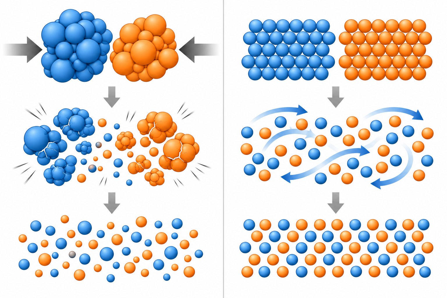
Dispersive mixing is size-reduction mixing. It demands that the mechanical stress applied to a cluster — whether shear stress, elongational stress, or a combination — exceeds a critical threshold. That threshold is set by the cohesive strength holding an agglomerate together or the interfacial tension stabilizing an immiscible droplet. Fall short of that threshold, even by a small margin, and the particle survives intact no matter how many times it circulates through the mixer.
Carbon black in rubber compounding is the textbook example. During combustion, individual carbon black particles fuse into aggregates — these are the smallest primary units you can achieve through mixing. Those aggregates, in turn, are held together by weak van der Waals forces to form larger agglomerates. A dispersion mixer used in rubber processing must deliver enough localized stress to shatter those agglomerates into their constituent aggregates. If the stress falls below the cohesive force, you end up with clumps of undispersed carbon black that create uneven color, reduce reinforcement, and show up as visible defects in the final product. As one industry reference puts it, carbon black is one of the best examples of a cohesive material with a high affinity to agglomerate — its aggregates must be dispersed within the polymer to fully develop the desired properties.
The key takeaway? A high speed dispersion mixer contributes to this process not by stirring faster, but by generating enough stress in localized zones — narrow clearances, converging channels, or kneading disc nips — to crack those clusters apart.
How Distributive Mixing Spreads Components Uniformly
Distributive mixing operates on an entirely different principle. Instead of breaking particles down, it increases spatial homogeneity by repeatedly reorienting, dividing, and recombining material streams. Think of it as shuffling a deck of cards — each pass rearranges the position of every component without changing the size of any individual card.
Imagine blending two compatible color concentrates into a polymer matrix. Both concentrates are already at their target particle size. No cohesive forces need to be overcome. The challenge is purely geometric: you need every tiny region of the final product to contain the correct ratio of each colorant. Narrow kneading discs in a twin-screw extruder achieve this by slicing through the melt in a scissoring action, dividing and layering the material with each revolution. In solids processing, techniques like plow mixing for dispersing solids rely on a similar convective mechanism — plowshare tools lift and throw material streams into overlapping trajectories, creating rapid spatial randomization without requiring the high stress thresholds associated with agglomerate breakup.
The stress requirement here is modest. You need enough energy to move the material around, but not enough to fracture anything. In fact, applying excessive stress during a purely distributive task wastes energy, raises melt temperature, and can degrade sensitive polymers or break the aspect ratio of reinforcing fibers.
Choosing the Dominant Mechanism for Your Application
The following table lays out the fundamental differences between the two mechanisms across the dimensions that matter most on the shop floor:
| Dimension | Dispersive Mixing | Distributive Mixing |
|---|---|---|
| Primary function | Break agglomerates or droplets into smaller fundamental units | Spread components uniformly throughout the matrix |
| Stress requirement | High — must exceed cohesive or interfacial forces | Low to moderate — sufficient to reorient and rearrange |
| Dominant flow type | Elongational and high-shear flow | Repeated splitting, reorientation, and recombination |
| Equipment examples | Wide-disc kneading blocks, Banbury-type internal mixers, rotor-stator dispersing mixers | Narrow-disc kneading blocks, static mixers, distributive mixing elements, plow mixing for dispersing solids in dry blending |
| Common applications | Carbon black in rubber, TiO2 pigment dispersion, immiscible polymer blend morphology control | Additive masterbatch letdown, compatible polymer blending, uniform colorant distribution |
In practice, most real compounding operations require both mechanisms working in sequence. Dispersive action comes first — agglomerates must be shattered into their primary particles before anything else matters. Distributive action follows, spreading those now-fine particles evenly throughout the polymer matrix. A product can be distributed but not dispersed, leaving large agglomerates evenly spaced across the part — still a failure. It can also be dispersed but not distributed, with fine particles clustered in one region while other zones are starved. Only when both mechanisms are satisfied do you achieve a truly homogeneous compound.
The critical engineering decision, then, is identifying which mechanism is rate-limiting for your specific formulation. If you are compounding a high loading of cohesive fillers, the bottleneck is almost certainly dispersive stress — and a dispersing mixer configuration with wide kneading discs, restrictive stagger angles, and high fill levels in the mixing zone is the right response. If your additives are already at target particle size and simply need to be blended uniformly, over-engineering the dispersive zone wastes energy, raises melt temperature, and risks degrading your polymer. Matching the dominant mechanism to the actual material challenge is what separates efficient compounding from expensive guesswork — and it sets the stage for understanding the physics that govern each mechanism at a deeper level.
The Physics of Particle and Droplet Breakup
Knowing that dispersive mixing requires stress above a critical threshold is useful — but it raises a practical question. What kind of stress? Not all deformation acts equally on an agglomerate or a droplet. The type of flow field surrounding a particle determines how effectively force is transmitted to its surface, and this distinction has enormous consequences for equipment selection, screw design, and process optimization. Let's break down the physics into three areas that every process engineer should understand: the difference between shear and elongational stress, the capillary number framework for droplet breakup, and the cohesive forces that hold solid agglomerates together.
Shear Stress, Elongational Stress, and Why the Distinction Matters
Shear stress is the force per unit area applied tangentially to a fluid element — picture two neighboring layers of polymer melt sliding past each other at different velocities. The faster layer drags on the slower one, creating a velocity gradient. In a high shear dispersion mixer, for example, the narrow gap between a rotor and a stator generates intense shear as melt is forced through at high relative speed. This tangential force can deform and eventually rupture agglomerates or droplets, but it does so unevenly. One side of the particle is pulled forward while the opposite side is held back, creating a rotational component that competes with the stretching component.
Elongational stress — also called extensional stress — works differently. Instead of sliding layers past each other, elongational flow stretches a fluid element along its flow direction. Imagine melt being pulled into a converging channel: the material accelerates as the cross-section narrows, and every point along the particle surface experiences a stretching force oriented in the same direction. This is far more efficient at transmitting stress uniformly across an agglomerate or droplet surface.
How much more efficient? Research in twin-screw extrusion confirms that elongational flow plays a very important role in dispersive mixing and must be accounted for alongside shear flow — not treated as a secondary effect. In quantitative terms, purely elongational flow can be roughly twice as effective as simple shear at breaking up particles. This relationship is captured by the dispersive mixing index lambda (λ), a dimensionless parameter that quantifies the ratio of elongational to rotational deformation in a flow field. A λ value of 1 represents pure elongation — maximum dispersive efficiency. A value of 0.5 corresponds to simple shear, where half the deformation is rotational and contributes nothing to breakup. A value of 0 means pure rotation with zero dispersive capability. When evaluating screw element designs or mixer geometries, this index provides a direct, quantitative way to compare how effectively different configurations convert mechanical energy into actual particle breakup.
The practical implication? A high-speed mixer for color dispersion that relies purely on high-shear tangential flow is leaving performance on the table. Configurations that incorporate converging geometries, flow restrictions, or staggered kneading elements — all of which generate elongational flow — achieve better dispersion per unit of energy input. This is why experienced engineers look beyond rotational speed and pay close attention to the geometry of the mixing zone.
Capillary Number and Viscosity Ratio in Droplet Breakup
When the dispersed phase is a liquid — as in immiscible polymer blends — the physics of breakup shifts from fracturing solid bonds to overcoming interfacial tension. The key dimensionless parameter here is the capillary number (Ca), defined as the ratio of viscous stress acting on the droplet to the interfacial stress resisting deformation:
Ca = (η × γ̇ × R) / σ
Here, η is the matrix viscosity, γ̇ is the deformation rate, R is the droplet radius, and σ is the interfacial tension between the two phases. When Ca is low, interfacial tension dominates and the droplet simply deforms slightly before snapping back to a sphere. Breakup occurs only when Ca exceeds a critical value (Ca_crit), at which point viscous stress stretches the droplet beyond its ability to recover, and it fragments into smaller droplets.
Here is where things get interesting. The critical capillary number is not a fixed constant — it depends strongly on the viscosity ratio (p) between the dispersed phase and the matrix. Research on droplet deformation and burst in linear flow fields demonstrates that interfacial properties and the viscosity contrast between inner and outer fluids directly determine the critical conditions for breakup under different flow types. When the dispersed phase is much less viscous than the matrix (p << 1), the droplet deforms readily but tends to form long, thin threads rather than breaking cleanly. When the dispersed phase is much more viscous (p >> 1), the matrix cannot transmit enough stress to deform it at all — the droplet simply rotates. The most efficient breakup in simple shear flow occurs near a viscosity ratio of roughly 1, where stress transfer is optimal. In elongational flow, the window is far wider — breakup can occur even at much higher viscosity ratios, which is another reason elongational flow fields are preferred for dispersive mixing of immiscible blends.
For process engineers working with blends like PA/PP or PC/ABS, these physics directly inform formulation and equipment decisions. Adjusting the matrix viscosity through temperature control or polymer grade selection shifts the viscosity ratio toward the breakup-favorable zone. Compatibilizers reduce interfacial tension, lowering Ca_crit and making breakup achievable at lower stress levels. Both strategies complement equipment-driven approaches to intensifying the flow field.
Cohesive Forces in Solid Agglomerates
Solid filler agglomerates present a different challenge than liquid droplets because the forces holding them together are not governed by interfacial tension alone. Carbon black, TiO2, silica, and other common fillers form agglomerates through a combination of van der Waals attractions and electrostatic forces acting between individual particles or aggregates. The strength of these bonds depends on the surface area in contact, the separation distance between particles, and the surface chemistry of the filler. Studies on filler dispersion in elastomers confirm that hydrodynamic forces during mixing must counteract these cohesive van der Waals attractions to fragment agglomerates into smaller aggregates that distribute uniformly within the matrix.
A critical misconception trips up many operators at this point: the belief that simply cranking up screw speed will always improve dispersion. Sounds logical — faster rotation means higher shear rate, which should mean more force on the particle, right? Not necessarily. Here is why.
The stress experienced by an agglomerate is the product of the local viscosity and the deformation rate: τ = η × γ̇. In a Newtonian fluid, viscosity is constant, so doubling the shear rate truly doubles the stress. But polymer melts are non-Newtonian — specifically, they are shear-thinning. As shear rate increases, viscosity drops. In many cases, the viscosity decrease partially or fully offsets the rate increase, meaning the actual stress on the agglomerate barely changes — or even decreases. You have spent more energy, generated more heat, and potentially degraded the polymer, all without improving dispersion.
This is precisely why geometry matters more than speed. The stress field depends on the flow channel design — narrow clearances, converging sections, and kneading block configurations that force melt through tight gaps at controlled rates. A well-designed dispersive mixing zone in a twin-screw extruder creates localized regions of high stress through geometry, not just rotational velocity. A soil dispersion mixer used in geotechnical testing, for instance, applies a similar principle: controlled mechanical action at defined clearances breaks apart soil agglomerates reliably, regardless of motor speed fluctuations.
Even evaluating a second hand dispersion blade mixer for a budget-conscious operation requires scrutiny of the blade geometry and tip clearances rather than focusing solely on the motor's RPM rating. Worn blades with enlarged clearances lose their ability to generate the localized stress concentrations needed for agglomerate breakup — a point we will revisit when discussing wear indicators in twin-screw kneading elements.
The interplay between viscosity, geometry, and deformation type ultimately determines whether your process delivers the stress intensity that agglomerates and droplets actually need. Understanding these physics gives you a rational basis for deciding where to invest — in screw element design, temperature control, formulation adjustments, or flow channel geometry — rather than defaulting to the instinct of simply running faster. That rational basis becomes especially important when the material itself dictates sharply different dispersive requirements, which is exactly where the discussion turns next.
When Your Process Demands Dispersive Mixing
Understanding the physics of breakup is one thing. Knowing when your specific formulation actually requires intense dispersive action — and when it does not — is the decision that separates efficient compounding from wasted energy and degraded polymer. Not every material challenge calls for the same approach, and applying maximum stress indiscriminately is just as costly as applying too little. Here is a practical framework for matching the dominant mixing mechanism to the real demands of your material system.
Solid Filler Agglomerates and Pigment Dispersion
When your compounding task involves tightly bonded agglomerates — carbon black in rubber, TiO2 in polyolefin masterbatch, or concentrated pigment preparations — dispersive mixing is unquestionably the dominant requirement. These materials arrive at the extruder with cohesive forces that simple convective blending cannot overcome. The stress applied in the mixing zone must physically fracture those clusters into their primary particles or aggregates before any distributive mechanism can spread them uniformly.
Three filler properties dictate how much stress intensity the process must deliver:
Surface treatment. Surface coatings on fillers like TiO2 — typically aluminum oxide, silicon oxide, or organic treatments — are applied specifically to reduce interparticle attraction and improve compatibility with the polymer matrix. Research on TiO2 pigmentation in polyethylene films confirmed that surface-treated particles (containing Al, Si, and C-based coatings) help moderate cohesive forces between particles and enhance compatibility with nonpolar polyolefins. Well-treated fillers require less dispersive energy because their interparticle bonds are weaker. Untreated or poorly treated fillers demand significantly higher stress to achieve equivalent dispersion quality — a consideration that directly affects screw element selection in a lab dispersion mixer or production-scale extruder alike.
Particle size distribution. Finer particles have higher surface area per unit volume, which means more contact points between neighbors and stronger total van der Waals attraction within each agglomerate. A 200 nm TiO2 pigment grade forms much more tenacious agglomerates than a coarser 1-micron grade. Breaking those fine-particle clusters demands not only higher peak stress but also sufficient residence time in the high-stress zone — a single brief pass may fracture only the outermost layer of the agglomerate while its core survives intact.
Loading level. As filler concentration climbs, particle-particle interactions multiply and the melt viscosity rises. High-filler compounding formulations — masterbatch grades can reach 70-80% filler loading — face compounding difficulties including agglomeration due to poor dispersion, surface defects from surviving filler clusters, and reduced mechanical properties. At these extreme loadings, the process must deliver intense and sustained dispersive stress throughout the mixing zone. Any shortfall shows up immediately as specks, streaks, or mechanical failures in the finished product.
For pigment applications specifically, the link between dispersion quality and optical performance is direct. The same TiO2 study demonstrated that masterbatch concentrates with better particle dispersion — achieved through ultrasound-assisted melt extrusion — produced films with measurably superior whiteness and covering power. Conversely, agglomerated particles wasted much of their pigmentary potential because clustered particles scatter light far less efficiently than individually dispersed ones. A high intensity mixer for color dispersion earns its value precisely here: every agglomerate that survives the mixing zone represents pigment you have paid for but cannot use.
Immiscible Polymer Blends and Morphology Control
Polymer blends like PA/PP, PC/ABS, or HDPE/PA6 present a fundamentally different dispersive challenge. Instead of fracturing solid bonds, the process must overcome interfacial tension to break large dispersed-phase droplets into the target morphology — typically a fine, uniform droplet distribution in the sub-micron to few-micron range. The resulting morphology is not just a processing detail; it directly controls end-use performance.
Impact strength, for example, depends heavily on the size and uniformity of rubber or elastomer droplets dispersed in a rigid matrix. Oversized droplets act as stress concentrators rather than energy absorbers, reducing toughness rather than enhancing it. Barrier properties in multilayer or blend-based packaging films depend on achieving a dispersed phase morphology that creates tortuous paths for gas diffusion. Optical clarity in transparent blend applications requires droplet sizes well below the wavelength of visible light — any droplet large enough to scatter light creates haze.
The capillary number framework discussed earlier governs this breakup. Viscosity ratio, matrix viscosity, and interfacial tension collectively determine whether a given flow field can fragment the dispersed phase. Compatibilizers shift the equation favorably by reducing interfacial tension, lowering the critical stress threshold for breakup, and suppressing coalescence that would otherwise undo the dispersion achieved upstream. Without adequate dispersive intensity, no amount of compatibilizer will compensate — the droplets simply never reach the size range where stabilization becomes effective.
When Distributive Mixing Alone Suffices
Not every formulation needs the intense stress zones described above. Recognizing when distributive mixing alone is sufficient prevents unnecessary energy consumption, excessive melt temperature rise, and polymer degradation.
Situations where distributive mixing dominates include:
Additive masterbatch letdown. When a pre-dispersed masterbatch — where the pigment or additive has already been broken into primary particles during concentrate production — is let down into a natural resin, the remaining task is purely spatial: spread the already-fine particles evenly throughout the matrix. Applying high dispersive stress here serves no purpose and risks thermal degradation of the carrier resin.
Compatible polymer blending. Miscible or highly compatible polymer pairs mix at the molecular level through diffusion. Mechanical mixing only needs to create thin enough striations for interdiffusion to complete the job. High-stress kneading blocks are not required and may unnecessarily increase melt temperature.
Low-viscosity liquid incorporation. Adding liquid additives, plasticizers, or processing aids into a polymer melt requires distribution, not dispersion. The liquids already exist as a continuous fluid phase — the goal is to distribute them uniformly, not break them into smaller droplets (which would require interfacial tension to exist between miscible components).
Applying excessive dispersive stress in any of these situations wastes energy directly through motor load and indirectly through the cooling capacity needed to manage elevated melt temperatures. In fiber-reinforced systems, unnecessary high-stress zones shatter glass or carbon fiber lengths, degrading the very reinforcement the formulation depends on. The solid dispersion mixer configuration that works brilliantly for breaking apart TiO2 agglomerates would be actively destructive in a long-glass-fiber compound.
So how do you know which side of this line your process falls on? The following indicators signal that dispersive mixing is the rate-limiting step in your operation:
- Visible agglomerates, specks, or undispersed clusters in the finished product — even at correct formulation ratios
- Mechanical properties (tensile strength, elongation at break, impact resistance) falling below expected values despite proper additive loading
- Inconsistent color across the part or from batch to batch, indicating pigment clusters that scatter light differently than fully dispersed particles
- Speck counts or gel counts exceeding specification limits during quality inspection
- Surface roughness or pitting on molded or extruded parts caused by surviving filler clusters disrupting flow at the die or mold wall
- Opacity or haze levels in films deviating from target due to oversized dispersed-phase domains
If none of these symptoms appear and your quality metrics are on target, your dispersive mixing is likely adequate — and your optimization effort is better directed at distributive uniformity, throughput, or thermal management. Recognizing that boundary accurately saves both time and capital, and it focuses equipment investments where they actually move the needle. The question then becomes: which equipment platforms deliver the dispersive stress your material demands — and how do their designs accomplish it?
Equipment Types and Mixer Designs for Dispersion
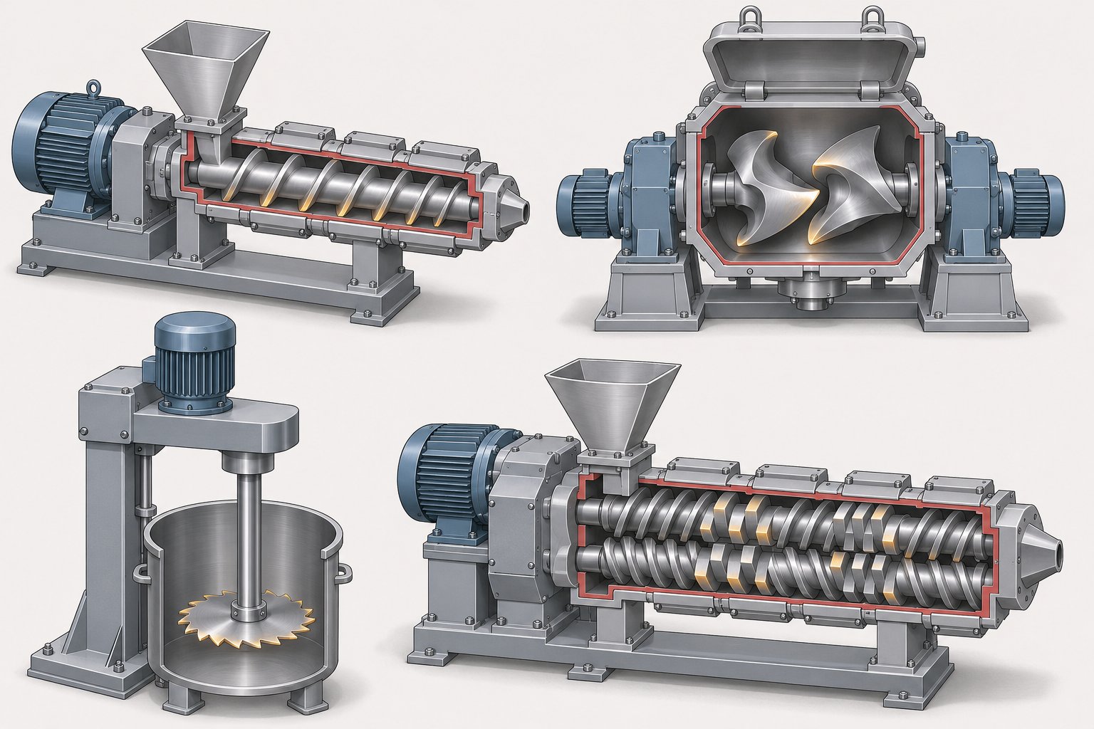
Every piece of mixing equipment generates stress differently — through different geometries, at different intensities, and in different flow patterns. Choosing the wrong platform for your material system means either falling short of the stress threshold your agglomerates demand or overshooting it and wasting energy while degrading the polymer. A clear understanding of how each major equipment category creates dispersive action helps you match the machine to the task before a single pellet hits the hopper.
Single-Screw Extruder Dispersive Mixers
Single-screw extruders were not originally designed for intensive mixing — they are fundamentally pumps. Their drag-flow mechanism moves melt forward along the screw channel, and without special modifications, the stress fields they generate are relatively modest. To compensate, engineers developed dedicated mixing sections that create localized high-stress zones within the screw profile.
The Maddock mixer (also known as the Union Carbide mixer) is one of the most widely used designs. It features parallel barrier-flight channels that force melt to flow over a narrow clearance between an inlet flute and an outlet flute. The tight gap over the barrier flight subjects every fluid element to an intense shear field, ensuring that agglomerates above a certain size are fractured as they cross the barrier. The Egan mixer operates on a similar principle but modifies the channel geometry to alter the pressure drop and flow distribution across the barrier. Dulmage-style sections use a series of slotted rings that repeatedly divide and recombine the melt stream, combining dispersive and distributive effects in a compact length. Pin-type mixing sections — where pins protrude from the barrel into interrupted screw flights — disrupt streamlines and force melt through high-stress zones around each pin.
Each of these designs improves upon a plain metering screw, but all face an inherent limitation. Patent literature on screw extruder dispersive mixing elements documents extensive efforts to enhance single-screw performance through novel flight geometries, confirming that the single-screw platform requires deliberate engineering intervention to achieve meaningful dispersion. Because a single screw relies on barrel-wall drag rather than intermeshing action, the stress intensity and the number of high-stress passes remain lower than what twin-screw platforms deliver — a constraint that matters most when processing highly cohesive fillers or tough immiscible blends.
Internal Batch Mixers and Kneaders
For rubber compounding and heavy-duty plastics mixing, internal batch mixers have been the workhorse for over a century. The Banbury mixer — a design featuring a figure-eight-shaped chamber with two counter-rotating rotors — generates its dispersive action in the narrow nip regions between the rotor tips and the chamber wall. As melt or uncured rubber is forced through these tapering gaps, it experiences intense shear and elongational stress that fractures agglomerates effectively.
Tangential-rotor Banbury designs rely on the clearance between each rotor tip and the wall for dispersive stress, while intermeshing rotor designs add a second high-stress zone in the nip between the rotors themselves. Four-wing rotor configurations were developed to increase the frequency of high-stress passes per revolution, shortening batch cycle times. Production-scale machines can process batches exceeding 450 kg with motor drives of 2985 kW and rotor diameters of 74 cm — scale that underscores how much energy these cohesive materials demand.
The batch nature of internal mixers gives operators direct control over residence time, temperature, and mixing sequence — advantages that make them indispensable for complex rubber formulations requiring precise staging of fillers, oils, and curatives. The trade-off is throughput: every batch must be loaded, mixed, dumped to a mill or extruder for cooling and forming, and then the cycle restarts.
High-Speed Dispersers and Rotor-Stator Designs
Outside polymer processing, high-speed dispersers and rotor-stator mixers dominate in coatings, inks, adhesives, and chemical processing — applications where lower-viscosity fluids need rapid particle size reduction. A typical saw-tooth dispersion blade mixer uses a serrated disc rotating at tip speeds of 5,000 feet per minute or higher. The blade creates a vortex that pulls material from the batch into the high-velocity zone at the blade periphery. The intense velocity gradients near the dispersion mixer blades fracture soft agglomerates and wet out pigment surfaces. Industry comparisons between saw-tooth dispersers and rotor-stator mixers highlight their distinct operating characteristics: saw-tooth blades excel at deagglomeration and wetting in the open-batch format, while rotor-stator designs force fluid through precisely machined gaps between a high-speed rotor and a stationary stator, generating extremely localized shear for fine emulsification and particle size reduction.
Neither platform delivers the elongational flow fields or the sustained stress history that polymer melt compounding demands. Their value lies in lower-viscosity systems where the stress thresholds for breakup are orders of magnitude lower than those of, say, carbon black agglomerates in an EPDM matrix.
Comparing Dispersive Mixing Equipment at a Glance
The table below maps each major equipment category against the dimensions that drive equipment selection decisions:
| Equipment Type | Typical Application | Stress Generation Mechanism | Throughput Mode | Relative Dispersive Intensity |
|---|---|---|---|---|
| Single-screw extruder with mixing section (Maddock, Egan, Dulmage, pin) | Polymer pelletizing, color compounding, film extrusion | Barrier-flight clearances, pin disruptions, slotted ring channels | Continuous | Low to moderate |
| Internal batch mixer (Banbury, intermeshing rotor) | Rubber compounding, heavy-duty plastics masterbatch | Rotor tip-to-wall nip, inter-rotor nip in intermeshing designs | Batch | High |
| High-speed saw-tooth disperser | Coatings, inks, adhesives | High-velocity blade periphery creating sharp velocity gradients | Batch | Moderate (in low-viscosity systems) |
| Rotor-stator mixer | Emulsions, fine dispersions, chemical processing | Precise rotor-stator gap generating extreme localized shear | Batch or continuous (inline) | Moderate to high (in low-viscosity systems) |
| Co-rotating twin-screw extruder with kneading elements | Polymer compounding, masterbatch, filled systems, blends, recycling | Kneading disc nips, inter-screw calendering, converging flow channels | Continuous | High to very high |
One platform stands out for its versatility across the widest range of dispersive challenges: the co-rotating intermeshing twin-screw extruder. Its modular screw design — interchangeable conveying, kneading, and mixing elements assembled on splined shafts — allows engineers to build custom stress profiles tailored to each formulation. Material flows in a figure-eight path between intermeshing screws, experiencing both shear and elongational deformation as it passes through kneading disc nips and the calendering zone between screws. This continuous dispersion mixer platform handles everything from carbon black in rubber to TiO2 in masterbatch to immiscible blend morphology control, adjusting intensity through element geometry rather than requiring a fundamentally different machine for each task.
That modularity, however, means the real engineering challenge shifts from choosing a machine to configuring the screw elements within it — selecting the right kneading block widths, stagger angles, and sequencing to deliver precisely the stress profile your formulation demands. That element-level design is where dispersive mixing performance is truly won or lost.
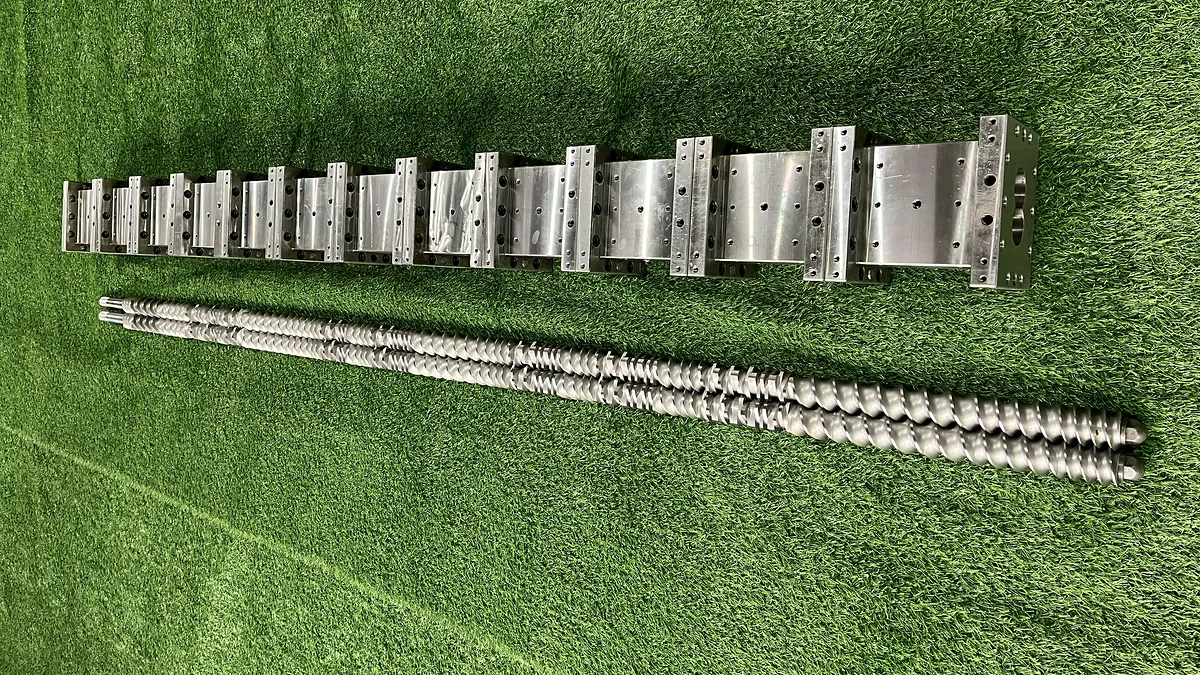
Twin-Screw Screw Elements That Drive Dispersive Mixing
Selecting a twin-screw extruder gets you the platform — but the screw elements you bolt onto those shafts determine whether your process actually breaks agglomerates or just pushes them through. Every conveying element, kneading block, and reverse segment plays a specific role in the stress profile your material experiences. The modular nature of co-rotating twin-screw extruders means you can rearrange, swap, and fine-tune these components without changing the machine itself. That flexibility is precisely what makes element-level design the highest-leverage decision in dispersion mixing.
Kneading Block Geometry and Stress Generation
Kneading blocks are the workhorses of any dispersive mixing zone. Each block consists of several individual discs — typically called kneading plates — mounted on the screw shaft at staggered offset angles. As the intermeshing twin screws rotate, material is squeezed between the tips of opposing discs and between disc tips and the barrel wall. These nip regions generate the intense shear and elongational stress fields needed to fracture agglomerates and break immiscible droplets down to target size.
Three geometric parameters control how aggressively a kneading block delivers dispersive action:
Disc width. Wider discs — designated KBW (full-disk-width) elements in some nomenclature systems — generate higher dispersive shear because each disc face contacts more material per revolution. NC State Extension research on screw functionality confirms that wider kneading elements promote dispersive mixing, while narrower elements shift the balance toward distributive action. If your formulation demands intense agglomerate breakup, wider discs are the starting point.
Stagger angle. The offset angle between adjacent discs in a kneading block — commonly 30, 45, 60, or 90 degrees — dictates both conveying behavior and stress intensity. A detailed review of kneading block applications notes that 45-degree elements offer the most ideal mixing balance, with 30-degree blocks providing gentler action and 60-degree blocks delivering relatively less efficient mixing. Neutral 90-degree elements deserve special attention: they generate zero forward conveying, which means material dwells longer in the mixing zone and accumulates more stress passes. Industry analysis of kneading block types confirms that 60-degree blocks deliver high shear and intensive mixing for demanding applications like glass-fiber-reinforced plastics and masterbatch production, while 30-degree configurations suit shear-sensitive materials like PVC or thermoplastic elastomers.
Clearance. The gap between disc tips and the barrel wall — and between the tips of intermeshing disc pairs — sets the minimum passage through which every fluid element must flow. Tighter clearances force melt through narrower high-stress zones, directly increasing peak stress. However, tighter gaps also raise local melt temperature and accelerate wear, especially with abrasive fillers.
The trade-offs here are real. Stacking aggressive kneading blocks — wide discs, tight stagger angles, minimal clearance — maximizes dispersive intensity but simultaneously reduces pressure-building capability, increases residence time in high-temperature zones, and elevates the thermal load on the polymer. Reverse kneading elements push material backward, creating maximum flow restriction and the highest stress levels in the screw profile, but extrusion processing guidelines recommend keeping reverse element lengths shorter than the screw diameter to prevent dangerous pressure peaks and excessive strain. In every case, the dispersive and distributive mixing balance depends on matching element aggressiveness to the actual cohesive forces in your material — not simply maximizing shear everywhere.
Configuring Screw Profiles for Dispersion and Venting
A kneading block sitting in the wrong position along the barrel is nearly as ineffective as having no kneading block at all. The complete screw profile must sequence functional zones in a logical progression that accounts for material state, stress requirements, and downstream processing needs.
A typical compounding profile follows this general architecture:
- Feed and conveying zone: Deep-flighted conveying elements (e.g., SK 40/40 or SE 30/30 types) move raw material quickly into the barrel without applying significant stress. The goal is efficient solids transport and initial melting.
- Dispersive mixing zone: Wide kneading blocks with moderate-to-aggressive stagger angles — positioned after sufficient melting has occurred — deliver the high stress needed for agglomerate breakup. This is where the critical dispersion mixing work happens. Reverse elements or neutral 90-degree blocks at the end of this zone create a melt seal that maximizes fill level and stress exposure.
- Distributive mixing zone: Narrower kneading discs or toothed mixing elements (such as Z-type elements) spread the now-fractured particles uniformly throughout the matrix without adding unnecessary thermal load. In some processes, a blade mixer in dispersion applications serves an analogous function at smaller scale — redistributing already-broken particles through repeated cutting and folding action.
- Venting zone: Low-fill, high-surface-area screw configurations — often wide-pitch conveying elements operating partially filled — create the conditions for volatile removal. Moisture, trapped air, and degradation byproducts escape through vacuum vent ports in this section. Element selection here directly affects devolatilization performance: if the melt film is too thick or the surface renewal rate too low, volatiles remain trapped and compromise product quality downstream.
- Pressure build-up and discharge: Progressively tighter-pitch conveying elements compress the melt and generate the die pressure needed for pelletizing, film extrusion, or profile output.
Getting this sequencing right is a blend of science and experience. Place the dispersive zone too early — before the polymer has fully melted — and solid polymer chunks absorb the stress that should be fracturing filler agglomerates. Place it too late, and the polymer has already passed through the vent zone with agglomerates intact, trapping volatiles inside undispersed clusters where vacuum cannot reach them.
Suppliers of modular screw elements provide the component-level flexibility that makes these configurations possible. NANHAIYA, for example, manufactures kneading blocks and segment screw elements for twin-screw compounding, masterbatch, pelletizing, and recycling equipment — offering process engineers options when configuring or replacing dispersive mixing and venting sections. The company evaluates element geometry, shaft matching, filler content, and wear conditions to support configuration changes, which matters enormously when a screw profile optimized for one product line needs to be adapted for a different filler system or polymer matrix.
Wear, Replacement, and Ongoing Optimization
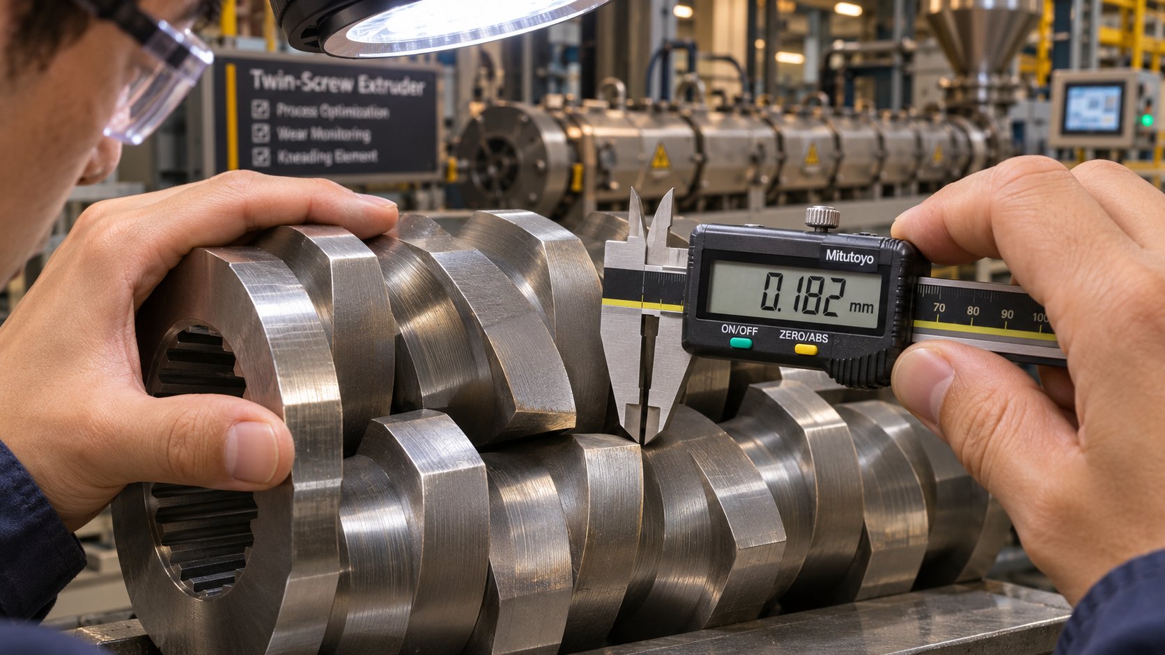
The same intense stress fields that fracture agglomerates also attack the elements themselves. Dispersive mixing zones experience the highest wear rates on any twin-screw extruder — particularly when processing abrasive fillers like glass fiber, calcium carbonate, or high-structure carbon black. Abrasive particles scour the disc tips and barrel liner surfaces, gradually enlarging the clearances that are responsible for generating peak stress.
As clearances open, the maximum achievable stress drops — and the first sign is often subtle. Product quality drifts before anyone notices the elements are worn. Recognizing the indicators early prevents costly scrap and rework:
- Gradual increase in speck counts or undispersed agglomerates in quality inspections, even though formulation and process parameters have not changed
- Declining mechanical properties — tensile strength, impact resistance, or elongation trending downward over weeks or months
- Color shift or reduced tinting strength in pigmented compounds, signaling that pigment clusters are surviving the mixing zone
- Increased specific energy consumption — the motor draws more power to achieve the same throughput because worn elements convey less efficiently, requiring higher screw speed to compensate
- Visible wear patterns during scheduled inspections — flattened disc tips, scoring on flight lands, or measurable diameter reduction beyond the manufacturer's tolerance
Replacing worn kneading blocks is not a repair — it is a process restoration. The geometry that originally generated your target stress field has physically changed, and no amount of process parameter adjustment can fully compensate for lost clearance. Working with element suppliers who can match shaft geometry, verify metallurgical specifications, and recommend wear-resistant grades for your specific filler system shortens downtime and ensures the replacement elements restore the original dispersion capability.
Operators familiar with a blade mixer in dispersion applications at smaller scale understand this principle intuitively: a dull or worn blade stops cutting effectively long before it stops spinning. The same logic applies to kneading block elements — rotational speed remains constant, but the dispersive work per revolution declines steadily as geometry degrades.
Viewing screw element maintenance as an ongoing optimization activity — not just a breakdown response — keeps your process within specification and prevents the slow quality erosion that erodes margins before anyone traces the root cause back to a worn kneading block. Of course, even a perfectly maintained screw profile cannot compensate if the element selection was wrong for the material in the first place — which is why the specific demands of each filler, pigment, and polymer blend system deserve their own detailed treatment.
Material-Specific Dispersive Mixing Requirements
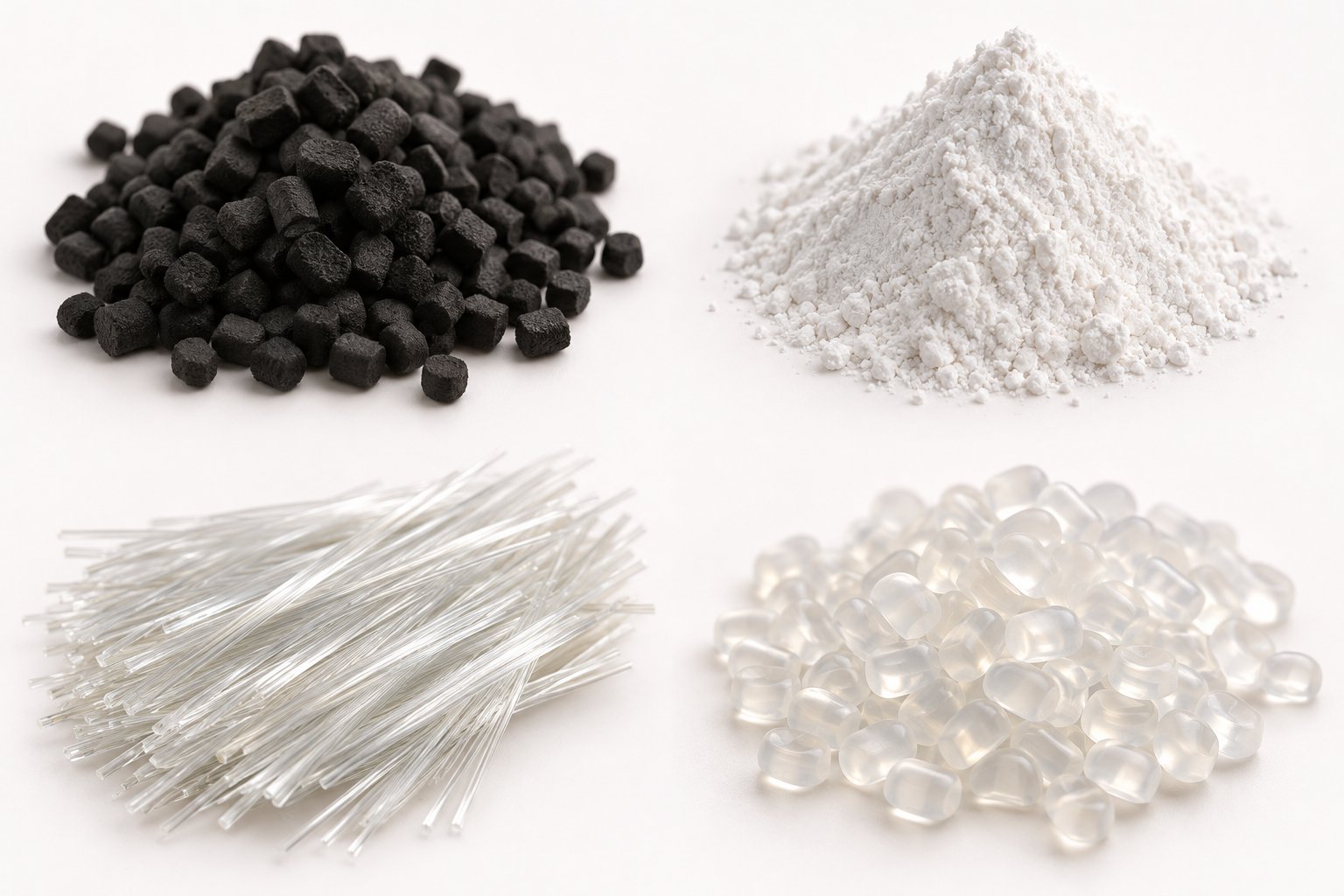
A perfectly configured screw profile for one material system can be completely wrong for another — even on the same extruder. Carbon black pellets, TiO2 pigment powder, glass fiber bundles, and immiscible polymer droplets all resist breakup, but the cohesive forces involved, the stress thresholds required, and the consequences of over- or under-processing differ dramatically. Treating them as interchangeable mixing challenges is one of the fastest routes to quality failures and wasted energy. Here is what each major material system actually demands.
Carbon Black in Rubber Compounds
Carbon black is arguably the most demanding filler from a dispersive mixing standpoint. During manufacturing, individual particles — typically 8 to 100 nanometers in diameter — fuse permanently into branched structures called aggregates. These aggregates are the smallest units you can achieve through any mechanical process. The problem is that aggregates do not arrive at the mixer individually. They pack together through van der Waals attraction into much larger agglomerates that can exceed tens of microns in size. Breaking those agglomerates apart, without any hope of breaking the aggregates themselves, is the entire dispersive challenge.
Two carbon black properties directly control how much mixing energy and stress intensity the process must deliver:
Structure grade. Structure refers to the degree of branching and complexity of each aggregate — quantified by dibutyl phthalate (DBP) oil absorption values. High-structure blacks have irregularly shaped, highly branched aggregates that interlock loosely, meaning the agglomerates they form are somewhat easier to fracture. Low-structure blacks pack more tightly, creating denser agglomerates with more particle-to-particle contact points and stronger total cohesive forces. In practical terms, switching from a high-structure N330 grade to a low-structure N772 grade can require a significant increase in mixing time and rotor speed to achieve equivalent dispersion.
Surface area. Finer carbon blacks — those with particle diameters below 20 nm — have dramatically higher surface area, which increases both the van der Waals attraction holding agglomerates together and the total energy needed to wet every newly exposed surface during breakup. As Birla Carbon's technical overview notes, finer particle sizes lead to increased reinforcement and abrasion resistance but require increased mixing time and energy to disperse. This trade-off is inescapable: the grades that deliver the best mechanical performance are also the most difficult to break down.
Rubber compounders typically address these demands with Banbury-type internal mixers that deliver intense stress in narrow rotor-tip nip regions over extended batch cycles. The mixing sequence matters as well — carbon black is usually added after the polymer has softened enough to transmit hydrodynamic stress to the agglomerate surfaces, but before curatives are introduced (which would begin crosslinking and make further dispersion impossible).
TiO2 and Pigments in Polyolefin Masterbatch
TiO2 pigment presents a different set of challenges than carbon black, though the underlying physics is related. The particles themselves — roughly 180 to 300 nm in diameter for rutile grades optimized for opacity — form agglomerates through van der Waals forces amplified by their high surface energy. Surface coatings of alumina, silica, and organic treatments reduce these interparticle forces, but they do not eliminate them. When agglomerates survive the mixing zone, the consequences are immediately visible.
Inadequate dispersion manifests in several measurable ways. Research on TiO2 pigmentation in polyethylene films demonstrated that masterbatch concentrates with superior particle dispersion produced films with measurably better whiteness and covering power — the contrast ratio improved because individually dispersed particles scatter light far more efficiently than clusters. Agglomerated particles effectively waste pigment: clustered TiO2 behaves optically like a single large particle rather than hundreds of individually scattering units, slashing the opacity and tinting strength you paid for. Color inconsistency, reduced hiding power, and surface defects like specks or gels all trace back to surviving agglomerates.
The rheology of the polymer matrix plays a critical role here. The same research found that lower-MFI polyethylene matrices — higher viscosity — produced better TiO2 dispersion because the more viscous melt transmits higher stress to the agglomerate surfaces during processing. Higher-MFI (lower-viscosity) matrices allow particles to re-agglomerate after initial breakup because the surrounding fluid cannot sustain the stress needed to keep them separated. This is a clear illustration of why distributive and dispersive mixing must be evaluated together: you can disperse particles in the high-stress zone, but if the matrix viscosity is too low downstream, coalescence undoes your work.
Masterbatch producers routinely optimize kneading block configurations specifically for pigment breakup — selecting wider discs, tighter stagger angles, and positioning the dispersive zone where the melt viscosity is high enough to deliver maximum stress transfer. The element choices that work for a 30 wt% TiO2 concentrate in PE with an MFI of 2 would be poorly suited for the same loading in an MFI-50 matrix, where the lower viscosity demands a fundamentally different approach to maintaining stress.
Glass Fibers and Mineral Fillers in Engineering Plastics
Glass-fiber-reinforced compounds introduce a competing requirement that makes them uniquely tricky. The fibers arrive as chopped bundles coated with a sizing agent. Adequate dispersive mixing must break those bundles apart and wet individual filaments with the polymer matrix — otherwise, dry fiber bundles act as defects rather than reinforcements. But here is the catch: the same high-stress zones that separate fiber bundles also break the fibers themselves, reducing their length and degrading the very mechanical properties they were added to provide.
Imagine the dilemma. You need enough stress to infiltrate and separate a tightly packed bundle of thousands of individual glass filaments. But every unnecessary pass through an aggressive kneading block snaps those filaments shorter. Tensile strength, flexural modulus, and impact resistance all depend on maintaining a critical fiber length — often targeted above 300 microns in the final pellet. Push too hard, and you end up with a compound full of well-dispersed but uselessly short fiber fragments.
The solution lies in screw element selection that prioritizes moderate stress with extended residence time rather than peak stress intensity. Wider-pitch conveying elements with gentle kneading sections — often 30-degree offset blocks or toothed distributive elements — apply enough force to separate bundles and wet fibers without the aggressive shearing that a 60-degree or reverse kneading block would impose. Fiber feeding location also matters: side-feeding glass fibers downstream of the main melting and dispersive zone ensures the polymer is already fully molten, so the fibers encounter a well-conditioned matrix rather than partially melted granules that would require additional mechanical work to process.
Mineral fillers like talc and calcium carbonate occupy a middle ground. They are less abrasive than glass fiber and less cohesive than carbon black, but at high loadings they still form agglomerates that require dispersive action. The key variable here is often particle shape — platy minerals like talc benefit from gentle delamination rather than brute-force fracture, preserving the high aspect ratio that provides stiffness and barrier properties in the final part.
Immiscible Polymer Blend Morphology
When two immiscible polymers are blended — PA/PP, PC/ABS, HDPE/PA6 — the dispersive challenge shifts from fracturing solid bonds to controlling a dynamic competition between droplet breakup and coalescence. Every pass through a high-stress zone stretches and fragments dispersed-phase droplets into smaller ones. But between those stress zones, droplets collide with each other and, if nothing prevents it, merge back into larger drops. The final morphology is not simply the result of how much stress you apply — it is the steady-state balance between these two opposing processes.
Compatibilizers alter this balance at the molecular level. Block or graft copolymers that localize at the interface between the two phases reduce interfacial tension, which lowers the critical capillary number and makes breakup achievable at lower stress. Equally important, compatibilizers create a steric or thermodynamic barrier at the droplet surface that suppresses coalescence. The practical effect is dramatic: a blend processed with an effective compatibilizer can achieve a stable sub-micron morphology under the same processing conditions where an uncompatibilized blend would coarsen to droplets ten times larger.
Understanding the distinction between distributive vs dispersive mixing becomes essential here. Dispersive stress fragments the droplets; distributive action ensures those droplets are spread uniformly rather than clustered in regions of high local concentration where coalescence rates skyrocket. Both distributive mixing and dispersive mixing must be sequenced and balanced to achieve the target morphology — skewing too far in either direction yields a blend with either coarse droplets (insufficient dispersive stress) or localized coalescence (inadequate spatial distribution).
For the process engineer, the actionable insight is that blend morphology is never locked in by a single mixing zone. It evolves continuously along the barrel, influenced by local stress fields, temperature-dependent viscosity ratios, and the presence or absence of compatibilizer at the interface. Screw profile optimization for blends therefore requires a different philosophy than for filler dispersion: instead of maximizing peak stress in one zone, the goal is to maintain stress above the critical capillary number across multiple zones while keeping the melt temperature low enough that the viscosity ratio stays in the breakup-favorable range.
Each of these material systems — carbon black, TiO2, glass fiber, mineral fillers, immiscible blends — demands its own dispersive strategy. A screw profile that excels at shattering carbon black agglomerates will destroy glass fiber length. A configuration gentle enough to preserve fiber integrity will leave TiO2 clusters intact. Recognizing these material-specific requirements before touching the screw profile is what prevents the costly trial-and-error cycles that consume time, material, and patience. Yet even with the right strategy in mind, certain process mistakes sabotage the results — mistakes so common that nearly every compounder has made at least one of them.
Common Mistakes That Undermine Dispersive Mixing
Knowing the right material strategy and selecting the right screw elements still leaves room for process errors that silently erode dispersion quality. Some of these mistakes are counterintuitive — they feel like improvements until the data proves otherwise. Others hide behind assumptions so deeply embedded in shop-floor culture that no one thinks to question them. Identifying these pitfalls is often faster and cheaper than adding another kneading block, because the fix is knowledge, not hardware.
Confusing Shear Rate With Shear Stress
This is the single most widespread misconception in compounding: the belief that turning up screw speed always delivers better dispersion. It sounds perfectly reasonable — faster rotation means a higher shear rate, and higher shear rate should mean more force on the agglomerate. In a Newtonian fluid, that logic holds. But polymer melts are not Newtonian. They are shear-thinning, meaning viscosity drops as deformation rate increases.
Recall that shear stress is the product of viscosity and shear rate: τ = η × γ̇. When you double the screw speed, you roughly double the shear rate — but the viscosity may drop by 30, 40, or even 50 percent depending on the polymer's shear-thinning behavior. Research on polymer mixture viscosity demonstrates how dramatically shear viscosity decreases with increasing shear rate across a wide range of polymers, following well-established models like the Bird-Carreau-Yasuda equation where the power-law exponent controls how steeply viscosity falls in the shear-thinning region. The net result? The actual stress experienced by an agglomerate may barely increase — or in extreme cases, it decreases. You have consumed more motor power, generated more frictional heat, pushed the melt temperature higher, and accelerated polymer degradation, all without meaningfully improving particle breakup.
The practical fix is thinking in terms of stress, not speed. Geometry — kneading block clearance, disc width, converging channel profiles — determines how efficiently a given shear rate converts into stress. A moderate screw speed through a well-designed dispersive zone often outperforms a high speed disperser mixer approach where raw RPM substitutes for intelligent flow-field design. When operators on the floor report that "running faster" did not fix their speck problem, this is almost always the explanation.
Neglecting Elongational Flow Contributions
Even engineers who correctly distinguish shear rate from shear stress often focus exclusively on shear-based mechanisms when troubleshooting dispersion problems. They scrutinize kneading block clearances, calculate tip-speed-based shear rates, and optimize rotor-to-wall gaps — all valid, but incomplete. Elongational flow fields, generated by converging channels, kneading block stagger transitions, and flow restrictions like reverse elements, are significantly more effective at breaking agglomerates and droplets per unit of energy input.
The dispersive mixing index lambda (λ) quantifies this directly. Simple shear flow registers at λ = 0.5, meaning half the deformation is rotational and contributes nothing to breakup. Pure elongational flow reaches λ = 1.0 — every bit of deformation stretches the particle toward failure. Simulation-experimental studies on PA66/silica composites confirm that increasing the number and strategic placement of kneading zones — which multiply the elongational flow transitions material encounters — substantially elevated cumulative strain and dispersive mixing ability, producing the smallest agglomerates and the most uniform filler distribution. Practitioners who evaluate their screw profiles only through a shear-rate lens miss the elongational contribution entirely and underestimate the dispersive potential of geometries that generate converging, accelerating flow fields.
What does this look like in practice? A high speed disperser mixing rules framework built solely around tip speed and gap clearance will undervalue elements like 45-degree kneading blocks, which generate strong elongational components at each disc-to-disc transition. It will also overlook the dispersive contribution of the converging nip between intermeshing screw elements — a zone where elongational deformation, not just shear, does much of the breakup work.
Overlooking Residence Time and Stress History
A single pass through a high-stress zone may fracture some agglomerates — but not all. Cohesive clusters are not uniform; they contain weaker outer bonds and stronger internal bonds. The outermost layer of an agglomerate may shatter on the first pass through a kneading block, exposing a denser core that requires a second, third, or fourth exposure to the same stress intensity before it finally breaks. This cumulative stress history — the total time a particle spends above the critical stress threshold — is what ultimately determines whether dispersion is complete.
Too many screw profiles treat the dispersive zone as a single station: one set of kneading blocks, one pass, done. The same PA66/silica study demonstrated this clearly — screw designs with multiple kneading zones distributed along the barrel (designated KN3-fme) reduced maximum agglomerate size from 19.29 μm down to 4.56 μm compared to single-zone designs, while also achieving the most uniform spatial distribution (VMR dropping from 1.43 to 1.09). Increasing the number of dispersive passes, with conveying sections in between to allow material reorganization and renewed surface exposure, outperformed simply making a single zone more aggressive.
Residence time also interacts with a double planetary dispersing mixer or any batch-format equipment in a subtle way: longer batch times allow more stress passes, but they also raise bulk temperature. In twin-screw extruders, feed rate directly controls fill level in partially filled kneading sections — starve-feeding reduces the amount of material in the mixing zone, lowering the stress transmitted to each particle even though the screw geometry has not changed.
Beyond these three core errors, several additional mistakes routinely undermine even well-intentioned process optimization efforts:
- Ignoring melt temperature rise from excessive dispersive zones. Every kneading block converts mechanical energy into heat. Stacking too many aggressive elements raises melt temperature beyond the polymer's thermal stability window, causing degradation, discoloration, and loss of molecular weight — problems that masquerade as formulation errors rather than screw design errors.
- Failing to account for matrix viscosity changes with temperature. As melt temperature climbs through the barrel, viscosity drops — and with it, the stress the melt can transmit to filler surfaces. A dispersive zone placed late in a hot barrel section may generate far less stress than the same element positioned upstream where the melt is cooler and more viscous.
- Using identical screw configurations for different filler types. A profile optimized for carbon black agglomerates — high cohesive strength, no fiber to protect — will shatter glass fiber lengths. A gentle profile designed for fiber preservation will leave TiO2 clusters intact. Each material system requires its own dispersive strategy, and copying configurations across product lines is a recipe for chronic quality problems.
- Neglecting the effect of feed rate on fill level and stress in kneading blocks. Partially filled kneading sections transmit less stress because not all disc surfaces contact material simultaneously. Increasing throughput without adjusting screw speed raises fill level and can improve dispersion — while decreasing feed rate at constant speed may paradoxically worsen it by starving the mixing zone.
- Assuming worn elements still deliver original performance. Clearance growth from abrasive wear reduces peak stress gradually, and the quality drift is slow enough that operators attribute it to raw material variability or seasonal temperature changes rather than element degradation.
Every one of these mistakes is correctable without capital investment — they require process understanding, not new equipment. Recognizing them shifts the optimization conversation from "we need a bigger machine" to "we need to use this machine more intelligently." That intelligence, in turn, depends on being able to measure dispersion quality objectively and link those measurements back to the specific screw parameters and flow conditions that produced them.
Measuring and Optimizing Dispersive Mixing Performance
Correcting process mistakes eliminates the obvious barriers — but how do you know when dispersion is actually good enough? Gut instinct and visual spot-checks only go so far. Quantifying performance requires metrics that connect flow-field characteristics inside the extruder to measurable product attributes outside of it. That connection — from screw element geometry to finished-part quality — is the foundation of any systematic optimization effort.
The Dispersive Mixing Index Lambda
The dispersive mixing index (λ) is the most direct way to evaluate how effectively a flow field converts mechanical energy into particle breakup. Think of it as a scorecard for the type of deformation happening inside your mixing zone. A value of λ = 1 indicates pure elongational flow — every bit of deformation stretches agglomerates toward failure. A value of λ = 0.5 corresponds to simple shear, where half the deformation is rotational and contributes nothing to breakup. A value of λ = 0 means pure rotation — the material spins in place with zero dispersive capability.
Computational fluid dynamics (CFD) tools calculate λ at every point in the flow domain, producing color-mapped visualizations that reveal exactly where in a screw element the elongational component dominates and where rotational dead zones waste energy. Research at Paderborn University used 3D CFD simulations with particle tracking to evaluate individual screw elements on co-rotating twin-screw extruders, determining the maximum shear stress and the integral of shear stress over residence time for every tracked particle. Their results showed that toothed mixing elements (ZME) generated high shear stresses across a broad, uniform distribution — meaning a large proportion of particles experienced effective dispersive action — while kneading blocks with 90-degree stagger angles produced narrower stress peaks concentrated at lower values. The study also confirmed that higher-viscosity polymers (lower MFR) generated significantly greater shear stresses for the same element geometry and rotation speed, reinforcing the principle that viscosity — not speed alone — governs stress intensity.
These simulation-based evaluations let engineers compare screw element designs before cutting metal or running trials. Instead of guessing whether a 45-degree kneading block outperforms a 60-degree one for a specific polymer system, you can quantify the λ distribution, peak stress, and cumulative stress integral across each option and select based on data. Equipment used in coatings and inks — a paint disperser mixer or a planetary disperser mixer, for instance — can benefit from similar flow-field analysis, though the lower viscosities involved shift the dominant stress mechanisms compared to polymer melt systems.
Product Quality Metrics Linked to Dispersion
Simulation indices describe what happens inside the mixer. Product quality metrics describe the outcome your customer pays for. Linking the two is what makes optimization actionable rather than academic. Dispersive mixing performance maps directly to a set of measurable outcomes that span visual, mechanical, and optical domains.
The following table connects each key quality indicator to its measurement method and the mixing parameters that most strongly influence it:
| Dispersion Quality Indicator | Measurement Method | Key Mixing Parameters |
|---|---|---|
| Filler dispersion rating | Microscopy per ASTM D2663 (carbon black) or ISO 18553 (thermoplastics); image analysis of cross-sections | Kneading block width, stagger angle, number of dispersive passes, melt viscosity |
| Speck or gel count | Thin-film inspection under transmitted light; automated camera-based gel counters on film lines | Peak stress in dispersive zone, cumulative stress history, element wear condition |
| Tensile and impact strength | ASTM D638 (tensile), ASTM D256 (Izod impact); standard mechanical testing | Filler wetting completeness, agglomerate survival rate, fiber length retention |
| Surface roughness | Profilometry (Ra, Rz); visual grading of molded or extruded surfaces | Maximum surviving agglomerate size, die-exit melt homogeneity |
| Optical haze in films | ASTM D1003 haze meter; spectrophotometry | Dispersed-phase droplet size (blends), pigment agglomerate size, morphology uniformity |
| Color strength and consistency (ΔE) | Spectrophotometer; CIE L*a*b* color space measurement against reference standard | Pigment dispersion completeness, distributive uniformity, number of stress passes |
Each row in this table represents a feedback loop. When speck counts climb above specification, the cause maps back to insufficient peak stress or too few dispersive passes — not to a formulation error. When ΔE values drift between batches, the root cause is often inconsistent stress history caused by wear-related clearance growth in the kneading zone. Treating these metrics as diagnostic tools rather than pass/fail gates is what transforms quality control from a gatekeeping function into a process optimization driver.
In batch-format equipment — whether a hockmeyer disperser mixer processing high-viscosity coatings or a butterfly disperser mixer handling paste-like formulations — the same quality indicators apply, though the measurement methods may shift toward grind-gauge readings (Hegman scale) and viscosity profiling rather than mechanical testing. The underlying principle remains identical: measure the outcome, trace it back to the stress field, and adjust accordingly.
Iterative Optimization of Screw Configuration
Optimization is never a single event. It follows a disciplined cycle that repeats as materials change, throughput targets shift, and quality specifications tighten. The practical workflow looks like this:
- Baseline characterization. Run the current screw configuration at standard conditions and measure every quality metric in the table above. Document the screw element sequence, element dimensions, wear condition, process temperatures, screw speed, and feed rate. This baseline becomes the reference against which every change is evaluated.
- Targeted modification. Based on the baseline data, identify the rate-limiting factor. If speck counts are high, increase dispersive intensity — swap to wider kneading discs, tighten the stagger angle from 60 degrees to 45 degrees, or add a second dispersive zone downstream. If melt temperature is excessive, reduce the number of aggressive kneading blocks or replace reverse elements with neutral 90-degree blocks that restrict flow without pumping material backward. If color uniformity is the issue but specks are absent, the bottleneck is distributive — add toothed mixing elements or narrow-disc kneading sections after the dispersive zone.
- Trial evaluation. Run the modified configuration under the same baseline conditions and re-measure every quality metric. Compare against the baseline quantitatively — not by visual impression alone.
- Iteration. Rarely does a single change hit the optimum. Each trial narrows the gap between current performance and the target, and the data from each run informs the next adjustment. Over several cycles, the screw profile converges on a configuration that balances dispersion quality, throughput, melt temperature, and energy consumption.
This cycle accelerates significantly when you work with screw element suppliers who understand the full context of your process. NANHAIYA, which supports configuration changes and replacement of worn segments for twin-screw compounding lines, reviews element geometry, shaft compatibility, and wear conditions to recommend targeted modifications — whether the task involves upgrading a kneading block configuration for better pigment breakup or replacing eroded elements that have drifted out of tolerance. Having a supplier who can match shaft spline profiles and verify metallurgical grades shortens turnaround between trial iterations and avoids compatibility errors that waste entire production runs.
It is worth emphasizing that even operations using a butterfly disperser mixer or other batch-format dispersion equipment follow the same iterative logic — adjust blade geometry or tip speed, measure the product, compare to the target, and refine. The scale and equipment differ, but the optimization discipline is universal.
Dispersive mixing optimization is never a one-time setup. Raw material suppliers change particle size distributions. New product specifications tighten color tolerances. Throughput targets increase. Screw elements wear. Each of these shifts moves the process away from its optimum, and only a systematic measurement-and-adjustment cycle keeps it on track. The companies that treat this as an ongoing engineering discipline — rather than a problem to solve once and forget — are the ones that consistently ship product that meets spec, at the lowest cost per kilogram, with the fewest surprises on the quality report.
Frequently Asked Questions About Dispersive Mixing
1. What is the difference between dispersive mixing and distributive mixing?
Dispersive mixing breaks down agglomerates, droplets, or clusters by applying stress that exceeds their internal cohesive or interfacial forces — it is fundamentally a size-reduction process. Distributive mixing, on the other hand, spreads already-sized components uniformly throughout the matrix through repeated splitting, reorientation, and recombination of material streams without requiring high stress. Most compounding operations need both in sequence: dispersive action first to fracture clusters into primary particles, then distributive action to ensure those particles are evenly spread. Identifying which mechanism is the bottleneck in your specific formulation is the key engineering decision that determines screw element selection and process efficiency.
2. Why does increasing screw speed not always improve dispersive mixing?
Polymer melts are shear-thinning fluids, meaning their viscosity drops as shear rate increases. Since shear stress equals viscosity multiplied by shear rate (τ = η × γ̇), raising screw speed increases the rate but simultaneously lowers viscosity. The two effects can partially or fully cancel each other, leaving the actual stress on the agglomerate unchanged or even reduced. The result is higher energy consumption, elevated melt temperature, and potential polymer degradation — without better dispersion. Effective dispersive mixing depends more on flow-channel geometry (narrow clearances, converging sections, kneading block design) than on raw rotational speed.
3. How do kneading blocks in twin-screw extruders create dispersive mixing?
Kneading blocks consist of staggered disc elements mounted at offset angles on the screw shaft. As intermeshing screws rotate, material is squeezed through nip regions between opposing disc tips and between disc tips and the barrel wall. These zones generate intense shear and elongational stress fields. Three geometric parameters control intensity: disc width (wider discs deliver more dispersive shear), stagger angle (tighter angles like 30-45 degrees increase forward stress exposure, while 90-degree neutral blocks maximize dwell time), and tip clearance (tighter gaps produce higher peak stress). Suppliers like NANHAIYA manufacture modular kneading blocks and segment screw elements that let engineers fine-tune these parameters for specific filler systems and polymer matrices.
4. Why is elongational flow more effective than shear flow for dispersive mixing?
Elongational (extensional) flow stretches a fluid element uniformly along its flow direction, transmitting stress evenly across the entire surface of an agglomerate or droplet. Shear flow, by contrast, applies force tangentially and introduces a rotational component that does not contribute to breakup. Quantitatively, pure elongational flow can be roughly twice as effective as simple shear at fracturing particles — captured by the dispersive mixing index lambda (λ), where λ = 1 represents pure elongation and λ = 0.5 represents simple shear. Screw designs incorporating converging channels, flow restrictions, and staggered kneading elements generate more elongational flow, achieving better dispersion per unit of energy input.
5. How do you know when dispersive mixing in your process is inadequate?
Several measurable indicators signal that dispersive mixing is the rate-limiting step: visible specks or agglomerates in the finished product despite correct formulation, mechanical properties (tensile strength, impact resistance) falling below expected values, inconsistent color or reduced tinting strength between batches, speck or gel counts exceeding specification limits, surface roughness on molded parts, and optical haze in films caused by oversized dispersed-phase domains. When these symptoms appear, the root cause typically traces back to insufficient peak stress, too few dispersive passes, or worn kneading elements with enlarged clearances that no longer generate the original stress intensity.
Written by
Nanhaiya Technical Team
Zhoushan Nanhaiya Plastic Machinery Co., Ltd.
The Nanhaiya technical team supports screw and barrel manufacturing projects through application review, technical communication, custom manufacturing coordination, and production and quality control.
Discuss Your Application
Related Articles
More insights on screw barrel technology and plastics processing.
Injection Molding Color Mixing: From Streaks to Flawless Consistency
Nov 19, 2026
Master injection molding color mixing with expert guidance on colorant types, screw design, process parameters, defect troubleshooting, and Delta E QC protocols.
Read Article
Wrong Extruder Breaker Plate? Spot the Signs Before Scrap Piles Up
Nov 19, 2026
Learn how to select, size, and maintain your extruder breaker plate. Covers hole geometry, pressure drop, polymer-specific specs, and troubleshooting tips.
Read Article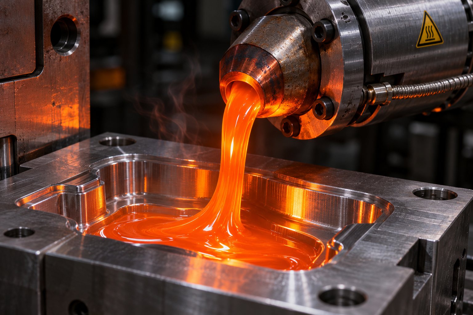
Injection Molding Melt Temperature: Why Your Barrel Settings Lie
Nov 19, 2026
Learn why barrel set points lie about injection molding melt temperature. Complete resin chart, measurement methods, defect troubleshooting, and optimization steps.
Read ArticleLooking for something else?
Search by material, symptom or product and jump straight to the relevant page.
These are navigation suggestions based on keyword matching — not a quotation, not a delivery commitment, and not a substitute for engineering review. Final specification is confirmed by our engineers against your drawings and processed material.
Need help with screw barrel selection?
Share your machine model, processed material and application. Our team can help with pricing and technical support.