

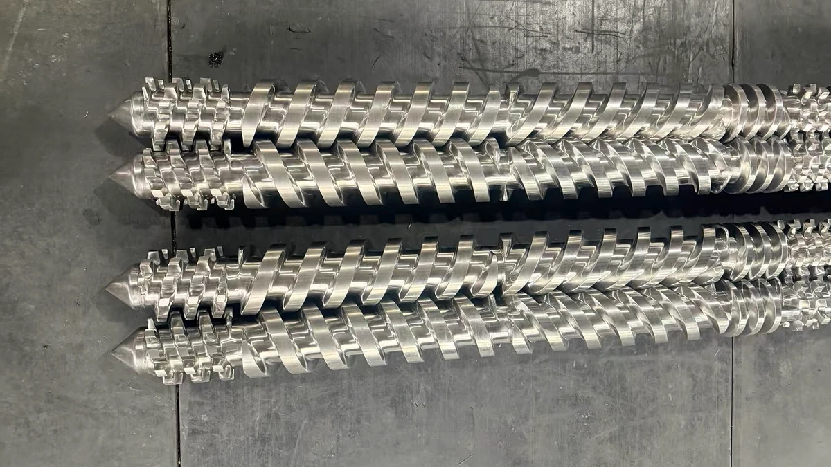
What Extruder Screw Types Are and Why They Matter
Every plastic product you encounter - from shrink wrap to automotive bumpers - passed through an extruder at some point. And inside that extruder, a single rotating component did most of the heavy lifting: the screw. Yet not all screws are created equal. Different extruder screw types exist because no single geometry can handle every polymer, every filler, and every end-product specification with equal efficiency.
An extruder screw is a helical shaft housed inside a heated barrel that simultaneously conveys, compresses, and melts polymer material before forcing it through a die. Different screw types exist because variations in polymer chemistry, filler content, and product requirements demand distinct flight geometries, compression behaviors, and mixing intensities.
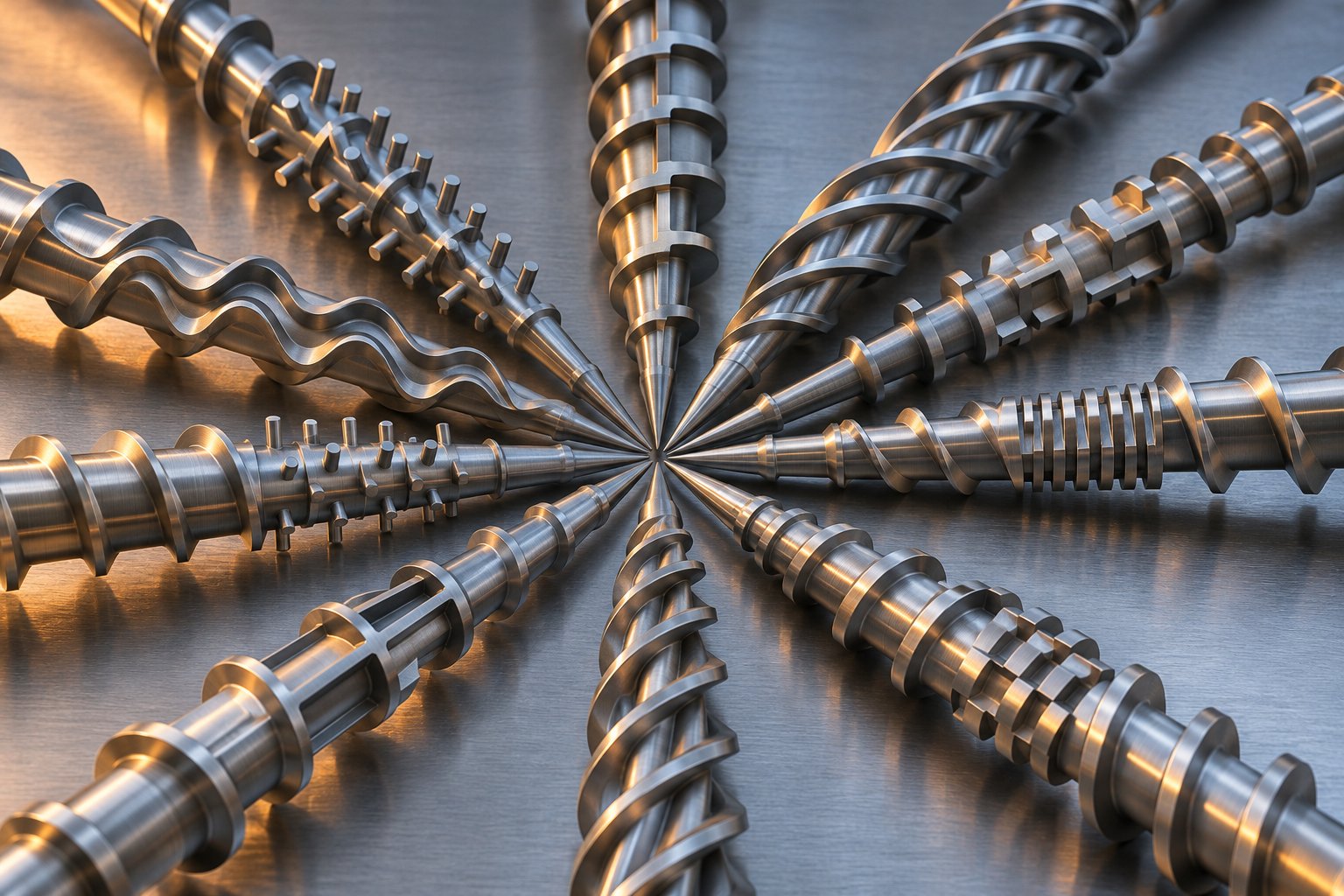
Here is the pattern that drives extruder screw evolution: each new design was engineered to solve a specific processing limitation of the design that came before it. General-purpose screws struggled with uneven melting, so barrier screws were born. Barrier screws lacked mixing intensity, so wave and pin-mixing sections followed. That problem-solution chain runs through every architecture covered in this article - from single-screw subtypes and twin-screw configurations to vented, grooved-feed, and specialty designs.
What an Extruder Screw Actually Does
Imagine dropping cold plastic pellets into one end of a steel tube and expecting a perfectly uniform, bubble-free melt to exit the other end. That transformation relies on three simultaneous functions the screw performs as it rotates inside the extruder barrels:
- Solids conveying - The deep-channeled feed section grabs pellets or powder from the extruder feed barrel and drags them forward using friction between the material, the screw flights, and the barrel wall.
- Melting (plastication) - As channel depth decreases, the material compresses. Friction-generated shear heat combines with external barrel heating to melt the polymer progressively along the screw length.
- Melt pumping - The shallow metering section at the discharge end builds and stabilizes pressure, ensuring the molten polymer flows into the die at a consistent rate and temperature.
All three stages happen concurrently along different zones of the screw. Change the depth, pitch, or flight configuration in any zone, and you alter throughput, melt quality, shear history, and residence time in ways that ripple through final product properties.
Why One Screw Design Cannot Serve Every Application
Think about the difference between melting a crystalline polymer like polyethylene - which transitions sharply from solid to liquid at a narrow temperature range - and processing an amorphous resin like polycarbonate, which softens gradually over a broad window. The screw geometry that efficiently melts one can over-shear or under-melt the other.
Layer on additional variables, and the challenge multiplies. Glass-fiber-filled compounds accelerate extruder screw wear issues on standard flights. Shear-sensitive PVC degrades if pushed through an aggressive mixing section. Hygroscopic nylons trap moisture that demands devolatilization zones most screws simply do not have. Each of these constraints points toward a different screw architecture - a different combination of channel depths, flight counts, barrier sections, and mixing elements tuned to that specific material and process.
Understanding these distinctions is not academic. Choosing the wrong screw type leads to poor melt homogeneity, degraded resin, excessive energy consumption, and premature wear on both screw and barrel. The sections ahead break down every major design category so you can match screw geometry to your resin with confidence.
Essential Extruder Screw Geometry Parameters and Terminology
Before comparing individual screw designs, you need a shared vocabulary. Every extruder screw - regardless of type - is defined by a handful of geometric parameters, and each one directly influences how polymer behaves inside the barrel extruder system. Change a single dimension, and you shift shear rates, melt temperatures, residence times, or output rates. The table below serves as a quick-reference glossary you can return to throughout the rest of this article.
| Parameter | Definition | Typical Range | Processing Effect |
|---|---|---|---|
| Flight | Helical ridge spiraling along the screw shaft; pushes material forward | Single or multiple starts | More flights improve conveying uniformity but reduce channel volume |
| Channel | The space between adjacent flights where polymer resides | Varies by zone | Wider channels increase throughput capacity; narrower channels raise shear |
| Root Diameter | Diameter of the screw shaft at the base of the channel | Increases from feed to metering zone | A larger root reduces channel depth, raising compression and shear on the melt |
| Pitch | Axial distance between corresponding points on adjacent flights | Often equals screw diameter (square pitch) | Increasing pitch boosts conveying speed and shear input |
| Lead | Axial distance the material advances in one full screw revolution | Equal to pitch on single-flight screws | On multi-start screws, lead exceeds pitch, increasing volumetric conveying |
| Helix Angle | Angle of the flight relative to a plane perpendicular to the screw axis | ~17.6° for square pitch | Steeper angles favor conveying; shallower angles favor pressure generation |
| Flight Width | Thickness of the flight land measured at the tip | ~10% of barrel diameter | Wider flights generate more shear heat in the clearance; narrower flights increase leakage flow |
| Flight Clearance | Radial gap between the flight tip and the barrel wall | 0.125 - 0.25 mm (new screws) | Tighter clearance limits leakage but raises local shear and heat; larger clearance reduces pumping efficiency |
| L/D Ratio | Ratio of flighted screw length to nominal barrel diameter | 24:1 to 36:1 | Higher L/D provides more residence time for melting, mixing, and pressure development |
| Compression Ratio | Ratio of feed-zone channel volume to metering-zone channel volume | 2:1 to 4:1 | Higher ratios suit low-bulk-density resins; lower ratios prevent over-shearing sensitive polymers |
Flight Geometry and Channel Depth Explained
Picture an extrusion screw laid flat. You would see the channel gradually getting shallower from the feed end to the discharge end. That depth progression is the primary mechanism behind compression. In the deep feed section, loose pellets fill the channel with plenty of air space between them. As the root diameter increases and the channel shallows through the transition zone, those pellets are squeezed together - air is driven backward, and frictional heat begins melting the polymer against the barrel wall.
Flight width and flight clearance work together in this process. A wider flight land creates a longer shear zone each time material passes beneath it, generating more viscous heat. The clearance gap - typically around 0.1% of barrel diameter on conventional screws - controls leakage flow, which is the thin stream of melt that sneaks backward over the flight tip. A small amount of leakage is normal and even beneficial for thermal homogeneity. Excessive leakage from worn flights, however, saps pumping efficiency and mimics the symptoms of an undersized screw extruder.
Corners where the flight meets the root are typically rounded rather than sharp. This avoids stagnation pockets where degraded polymer could accumulate and periodically break free as black specks in the product. It is a small detail, but one that separates a well-engineered extruder screw from a commodity one.
L/D Ratio and Compression Ratio in Practice
When someone describes a screw as "24:1" or "30:1," they are citing its length-to-diameter ratio. A 24:1 L/D is the most common general-purpose configuration. Counting turns is easy on a square-pitch screw because each turn covers roughly one diameter of axial length - so a 24:1 screw has approximately 24 flights of working length. An important nuance: the portion of the screw sitting beneath the feed opening should technically not be counted toward L/D, though many practitioners include it, making the screw appear longer on paper.
Why go longer? More L/D means more time and barrel surface area for heat transfer, melting, and mixing. A 30:1 or 36:1 screw extruder is common when processing resins that melt slowly, require intensive mixing, or need a vented devolatilization stage that demands additional barrel length.
Compression ratio, on the other hand, describes how aggressively the screw compacts material. It is calculated as the ratio of the feed-zone channel volume to the metering-zone channel volume - often simplified to the ratio of feed depth to metering depth on a constant-pitch screw. Typical values fall between 2:1 and 4:1. The general selection principle is straightforward: polymers with low bulk density relative to their melt density, such as flake regrind or foamed pellets, need higher compression to expel trapped air and consolidate the melt. Dense, pre-compacted pellets of crystalline resins like nylon or PET often perform well with moderate compression ratios around 3:1 to 3.5:1. Amorphous resins and shear-sensitive materials such as PVC typically call for gentler ratios closer to 2:1 to avoid excessive frictional heating.
Keep in mind that compression ratio alone does not fully define a screw. Two screws can share identical compression ratios yet differ dramatically in transition-zone length, flight geometry, and mixing capability - which is exactly why understanding the complete parameter set matters before evaluating specific designs.
General-Purpose Single Screws and Three-Zone Design
Two screws can share the same compression ratio and L/D yet perform very differently - and the reason almost always traces back to how the three functional zones are proportioned and shaped. The general-purpose (GP) three-zone screw is where that story begins. It is the oldest, simplest, and still the most widely installed plastic extruder screw architecture in the world. Every advanced design covered later in this article exists because engineers ran into a specific wall with this foundational layout and had to engineer around it.
A standard GP screw divides its working length into three distinct regions - feed, compression (sometimes called the transition zone), and metering - each with a constant geometry within its own boundaries. A classic square-pitch configuration uses equal zone lengths, meaning each zone occupies roughly one-third of the total flighted length. The flight lead equals the screw diameter, and the flight width stays at about 10% of that diameter from end to end. Sounds simple? It is. And that simplicity is both its greatest strength and the source of its most stubborn limitations.
Feed, Compression, and Metering Zone Functions
Imagine pellets tumbling from the hopper into the feed throat. They land in the deepest section of the screw channel - the feed zone - where the channel depth is typically around 20% of the screw diameter. This generous depth does two things: it maximizes volumetric intake so the screw stays fully loaded, and it keeps compaction pressure low enough that pellets slide forward without bridging. Friction between the pellets, the barrel wall, and the screw root is what drives solids conveying here. No melting is expected yet; the goal is simply to move as much material downstream as possible.
As the material enters the compression zone, the root diameter begins to increase and the channel shallows progressively. This taper squeezes the pellet bed against the extrusion barrel wall, expelling trapped air backward toward the feed throat and forcing polymer into tighter contact with the hot barrel surface. Approximately 80% of melting occurs at the barrel-side interface, where a thin melt film forms between the solid bed and the barrel wall. The screw's rotation drives viscous dissipation within this film - shear energy converts to heat, melting additional resin that gets swept into a growing melt pool on the trailing side of the channel. Research into how polymer melts in single-screw extruders has confirmed this barrel-side melting mechanism through cross-sectional solidification experiments.
By the time material reaches the metering zone, ideally all pellets have melted. The channel depth here is constant and much shallower - roughly 10% of the screw diameter on a standard design with a 2:1 compression ratio. This shallow channel generates high shear and builds the stable pressure needed to push melt through screen packs, adapters, and the die. It also provides a final opportunity for thermal mixing as the melt circulates within the channel cross section.
Zone proportions shift depending on the polymer. A screw designed for LDPE - a semicrystalline resin with a sharp melting point and relatively low bulk density - typically uses a longer feed zone and a gradual transition to ensure the solid bed compacts steadily without pressure spikes. A screw for nylon, which melts over a narrower temperature window and has higher bulk density, may shorten the feed zone in favor of a longer metering section for improved pressure stability. Zone ratios are commonly expressed as feed-transition-metering percentages of total L/D. A 50-25-25 split, for example, dedicates half the screw to solids intake and half to compression and pumping. Injection molding screws and barrels often use similar three-zone logic, though with shorter overall L/D values because the screw must also function as a reciprocating plunger.
Limitations That Led to Advanced Screw Types
For all its versatility, the GP screw carries inherent weaknesses - and they become painfully visible at higher throughput rates. The core issue is the solid bed breakup phenomenon. As the melt pool grows wider in the compression zone, the remaining solid bed narrows and eventually fractures. Pieces of the solid bed break free, float into the melt pool, and travel downstream as unmelted fragments. These fragments may reach the die and show up as gels, unmixed streaks, or visible specks in the final product.
Why does this happen? Melting capacity scales with the barrel surface area available for heat transfer, but it does not increase at the same rate as solids conveying when screw speed rises. According to research by Mark Spalding at Dow, doubling the screw speed roughly doubles the pumping capacity of the feed and metering zones, yet the melting flux increases by only a factor of about 1.4. The solid bed gets pushed farther downstream to recruit more barrel area for melting - and when the barrel runs out of real estate, unmelted solids discharge with the extrudate.
Here are the specific processing deficiencies that general-purpose screws exhibit under demanding conditions:
- Solid bed breakup - The narrowing solid bed fractures in the compression zone, releasing cold polymer fragments that contaminate the melt stream and cause product defects.
- Uneven melting across the channel width - The melt pool concentrates on one side of the channel while the solid bed clings to the other, creating large temperature gradients and viscosity differences within the same cross section.
- Output surging - Periodic pressure fluctuations - often synchronized with the screw rotation rate - arise from inconsistent melting and non-uniform melt temperatures. Experimental data show that GP screws exhibit melt-pressure standard deviations roughly four times higher than multi-channel designs running the same resin at the same speed.
- Rate-limited melting capacity - Because melting flux cannot keep pace with conveying at elevated screw speeds, the maximum usable output is capped well below the mechanical limit of the drive train.
- Poor thermal homogeneity - Recirculating vortex flows inside the metering channel create coiled-sheet morphologies with temperature gradients exceeding 10 degrees Celsius, leading to shot-to-shot or meter-to-meter variability in product dimensions.
These are not theoretical concerns. Cross-sectional photographs of solidified melt from GP screws reveal distinct white or off-color fragments surrounded by properly tinted resin - a direct visual signature of incomplete plastication. At moderate speeds the defects may be manageable, but push the screw beyond about 60-70% of its mechanical speed limit and extrudate quality degrades rapidly.
Each of these shortcomings pointed screw designers toward a clear engineering target. Solid bed breakup called for a physical barrier to keep solids and melt separated throughout the compression zone. Uneven melting demanded geometries that drain excess melt away from the solid bed to maximize barrel-side contact. And output surging pushed development toward multi-channel and wave architectures capable of dampening pressure oscillations at their source. Those solutions - barrier flights, Maddock mixers, wave screws, and more - are the subject of the sections that follow.
Barrier Screw Designs and Their Processing Advantages
Solid bed breakup, uneven melting, output surging - the previous section made it clear that general-purpose screws hit a performance ceiling well before the drive motor runs out of torque. So how do you keep the solid bed intact while simultaneously draining melt away from it? The answer is elegantly mechanical: add a second flight.
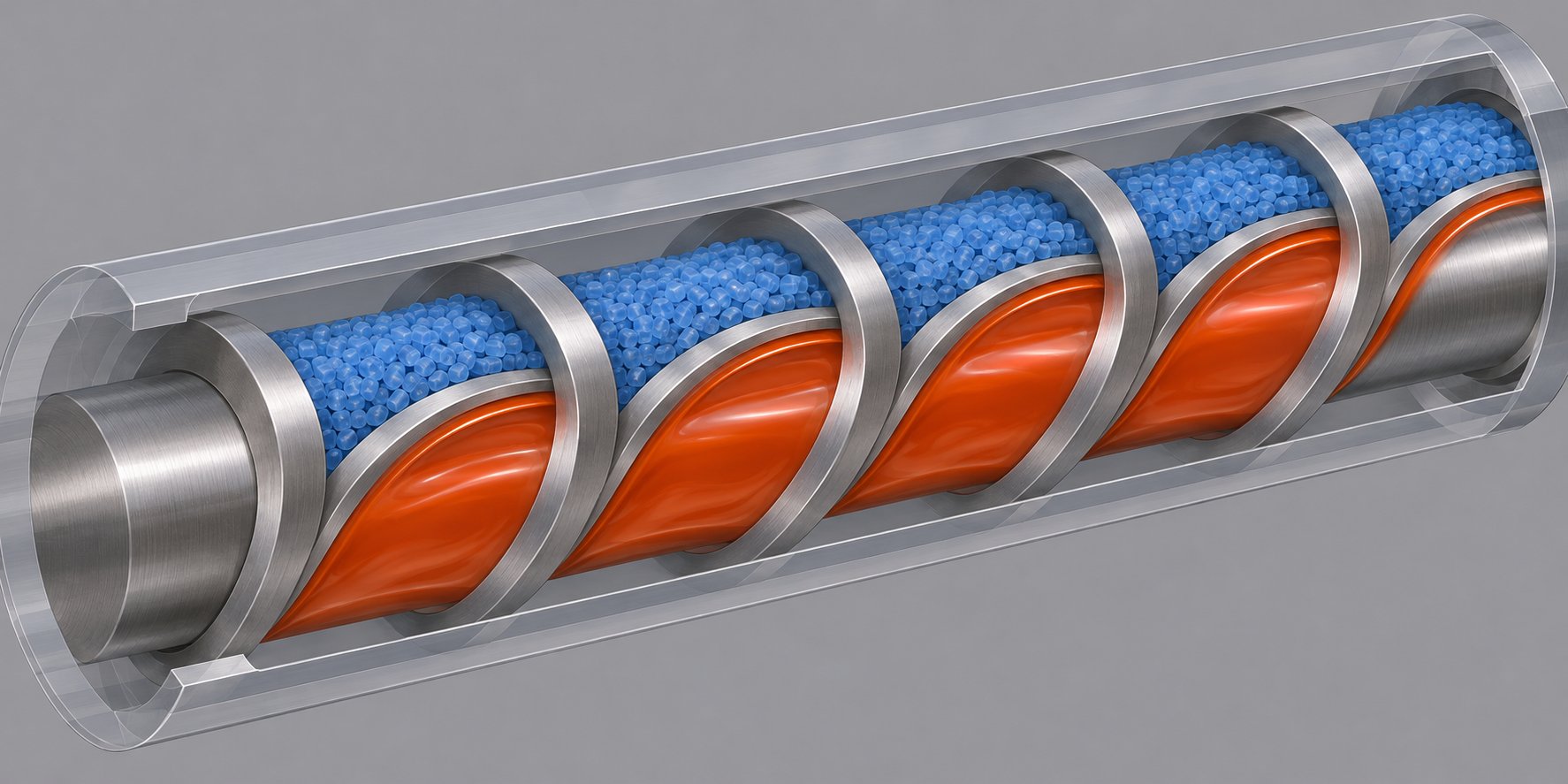
A barrier screw introduces a secondary helical flight - called the barrier flight - running alongside the primary (main) flight through the compression zone. This barrier flight has a slightly reduced outer diameter, creating a deliberate clearance gap between its tip and the barrel wall. The gap is large enough to allow molten polymer to pass over the barrier, yet too small for solid pellets or compacted granules to squeeze through. The result is two parallel channels spiraling down the screw: one dedicated to transporting solids, and one reserved exclusively for collecting melt.
Imagine a highway median that lets motorcycles slip through but blocks trucks. Molten resin, behaving as a viscous fluid, can flow over the barrier flight and into the melt channel. Unmelted solids, however, remain physically trapped in the solids channel where barrel-side melting continues uninterrupted. This forced separation is the core innovation behind every barrier design, and it directly eliminates the solid bed breakup problem that plagues conventional screw extrusion geometries.
How the Barrier Flight Prevents Solid Bed Breakup
In a general-purpose screw, solids and melt coexist in the same channel. As the melt pool grows, it compresses the solid bed against the trailing flight. Eventually the solid bed narrows to a point where it fractures - fragments drift into the melt pool and travel downstream as unplasticated debris. The barrier screw prevents this by providing a separate escape route for molten material.
Here is the mechanism step by step. As the screw rotates, a thin melt film forms between the solid bed and the hot barrel wall - exactly the same barrel-side melting process that occurs in a GP screw. The critical difference: instead of accumulating in a growing melt pool within the same channel, this freshly melted polymer is continuously scraped off by the barrel wall's relative motion and pushed over the barrier flight clearance into the adjacent melt channel. Because the melt channel steadily increases in cross-sectional area while the solids channel decreases, the solid bed maintains contact with the barrel surface throughout its length. It never narrows to a fragile sliver; it simply shrinks at a controlled rate until it is fully consumed.
The barrier flight clearance is the critical design variable. Too tight, and it restricts melt flow so aggressively that pressure spikes develop in the solids channel. Too loose, and semi-molten fragments sneak through, defeating the purpose of the barrier entirely. Typical barrier clearances range from roughly 1.5 to 3 times the primary flight clearance, though the exact value depends on the viscosity and melting characteristics of the polymer being processed. Getting this dimension right is what separates a well-performing barrier screw from one that merely adds cost without improving melt quality.
Maillefer, Standard Barrier, and MC3 Variants Compared
Not all barrier screws share the same channel geometry. In fact, as extrusion consultant Jim Frankland has noted, most people assume barrier designs all work about the same - but in reality there are substantial differences among them. The three primary architectures differ in how the solids and melt channels evolve along the screw's axial length, and that difference determines which polymers and applications each variant handles best.
Maillefer (Crossing) Barrier. One of the earliest barrier concepts, the Maillefer design uses a barrier flight that gradually crosses over the main flight helix. The solids channel maintains a nearly constant width while the melt channel progressively narrows. Because there is no sudden restriction of the solids-channel width at the start of the barrier section, this design handles hard or slippery polymers particularly well - their more fragile solid beds do not need to reshape abruptly to accommodate a geometry change. The wider, shallower melt channel also gives the crossing barrier strong head-pressure generating capability, which means it can often feed high-resistance dies without needing a lengthy metering section downstream.
Standard (Parallel/Barr) Barrier. Introduced after the Maillefer concept, the parallel barrier - often called the Barr screw after designer Robert Barr - runs its barrier flight roughly parallel to the main flight. The solids channel gradually narrows while the melt channel widens. This geometry provides significantly more barrel surface area in contact with the solids channel for a given axial length. On a typical 3.5-inch screw with 10 diameters of barrier flight, the parallel design offers approximately one-third more solids-channel area than a comparable Maillefer layout. Because melting capacity is largely proportional to the surface area available for solids melting, parallel barrier screws are the stronger choice for high-energy-demand polymers - those with high melting points, high specific heats, or significant shear-thinning behavior. The trade-off: the parallel barrier's narrow, deep melt channel generates less head pressure, so a metering section downstream is usually required when the die imposes significant back pressure.
MC3 and Dray-Lawrence Variants. These modified designs increase the lead (helical pitch) of the main flight within the barrier section beyond the standard square-pitch value. On a 3.5-inch screw, for example, increasing the lead by 25% to 4.375 inches (approximately 21.7 degrees helix angle) yields only 8 turns of barrier flight instead of 10 within the same axial length. The melting area increases by less than 10%, and even that modest gain is partially offset by reduced viscous dissipation per unit length at the longer helix angle. The real benefit of MC3-type designs is volumetric: the wider solids channel accommodates more material, enabling higher throughput rates. These variants also reduce disruption at the barrier-flight and melt-channel introduction point, making them well-suited for applications where output volume matters more than incremental melting efficiency. A DuPont-patented variation takes this further by retarding the main flight pitch to form the barrier channel backward, minimizing solid-bed disruption at the transition into the barrier section.
| Variant | Channel Geometry | Best-For Materials | Key Advantage | Key Limitation |
|---|---|---|---|---|
| Maillefer (Crossing) | Constant-width solids channel; narrowing melt channel; barrier flight crosses main helix | Low-energy polymers: LDPE, LLDPE, PP copolymers, soft or slippery resins | No abrupt solids-channel restriction; strong head-pressure generation; gentle solid-bed handling | Less melting area per unit length than parallel designs; may limit throughput on high-melting-point resins |
| Standard Parallel (Barr) | Narrowing solids channel; widening melt channel; barrier flight runs parallel to main flight | High-energy polymers: HDPE, nylon, PET, resins with high melting points or high specific heats | ~33% more solids-channel melting area than Maillefer for equal axial length; superior melt quality at high output | Requires downstream metering section for pressure generation; abrupt geometry change at barrier start can disrupt fragile solid beds |
| MC3 / Dray-Lawrence | Extended lead (longer helix angle) in barrier section; wider solids channel for increased volume | High-output commodity extrusion: HDPE pipe, PE blown film, PP sheet | Higher volumetric throughput; reduced solid-bed disruption at barrier introduction | Melting area gain under 10%; reduced viscous dissipation per unit length; may require longer barrier section for equivalent melt quality |
One additional design detail worth flagging: the exit end of the solids channel can be either closed or open. A closed-end design forces all material to pass over the barrier flight as melt, ensuring that nothing reaches the melt channel without full plastication. The risk? If melting is incomplete, the closed end can plug with solids, causing pressure fluctuations, accelerated screw wear, and poor thermal uniformity. An open-end design allows any remaining solids to exit the channel and relies on downstream mixing elements or a metering section to finish the job. Both configurations require careful thermal and rheological calculations to size correctly and maintain a wide processing window.
When a Barrier Screw Outperforms a General-Purpose Design
Barrier screws deliver their greatest advantage when processing semicrystalline polymers - PE, PP, nylon, PBT, PET - that exhibit a distinct melting point. These resins transition from a tightly packed crystalline solid to a low-viscosity melt over a narrow temperature range. That sharp phase change means the boundary between solid and melt is well defined, which is exactly the condition a barrier flight needs to function effectively. The solid bed stays compact on one side of the barrier, the melt flows cleanly over it to the other side, and the controlled separation drives highly efficient plastication.
Performance gains are not subtle. Processors switching from GP screws to properly specified barrier designs routinely report improved melt temperature uniformity, reduced pressure fluctuations at the die, and the ability to increase screw speed - and therefore output - without sacrificing extrudate quality. In high-volume screw extrusion applications like blown film, pipe, and sheet, those improvements translate directly to higher line speeds and less scrap.
The picture changes with amorphous or shear-sensitive resins. Polycarbonate, ABS, and PVC soften gradually rather than melting sharply, making the solid-melt boundary less distinct. A barrier flight designed for a crystalline resin may restrict flow prematurely or create excessive shear on a slowly softening amorphous melt, leading to thermal degradation, gels, or discoloration. For these materials, a GP screw with appropriate mixing sections - or a twin screw and barrel system for heavily compounded grades - often proves the more practical choice.
Selecting between Maillefer, parallel, or MC3 configurations also depends on the specific polymer. Crossing barriers suit lower-energy resins and hard or slippery pellets whose solid beds fracture easily under sudden geometry changes. Parallel barriers handle high-energy, high-output demands where maximizing melting area is the priority. And MC3 variants target commodity extrusion lines chasing throughput volume above all else. There is no universal best design - only the one matched to your resin's thermal, rheological, and physical properties.
Barrier screws solve the melting problem with remarkable effectiveness, but they were never intended to address mixing. A cleanly melted polymer stream still needs uniform temperature distribution, additive dispersion, and color homogeneity - tasks that require an entirely different class of screw elements.
Mixing Sections and Wave Screw Architectures
A perfectly melted polymer stream is only half the battle. If your resin carries color concentrates, stabilizer packages, mineral fillers, or blended components, the melt must also be thoroughly mixed - and the type of mixing matters as much as its intensity. Mixing sections bolted onto, or machined into, the downstream end of a screw are what transform a merely molten stream into a truly homogeneous one. Yet "mixing" is not a single action. Two fundamentally different mechanisms are at work inside every extruder screw barrel, and confusing them is one of the fastest routes to either overheated resin or poorly dispersed additives.
Dispersive vs. Distributive Mixing Principles
Think of dispersive mixing as breaking things apart and distributive mixing as spreading things around. They are complementary, not interchangeable, and most real-world extrusion applications require both in carefully balanced proportions.
Dispersive mixing subjects the melt to high shear stress - stress that exceeds the cohesive strength of agglomerates, gels, or undispersed pigment clusters. When molten polymer is forced through a narrow gap or restriction, the velocity gradient across that gap generates enough local stress to physically rupture tightly bound particle clusters into their primary constituents. This is the mechanism you need when breaking down carbon black agglomerates, eliminating gels in recycled streams, or reducing pigment particle size to achieve full color development. The trade-off is heat: every high-shear restriction converts mechanical energy into thermal energy, raising melt temperature and potentially degrading shear-sensitive resins.
Distributive mixing takes a different approach entirely. Instead of applying brute-force shear, it works by repeatedly dividing, reorienting, and recombining the melt stream. Imagine slicing a block of layered clay in half, stacking the halves, rotating the stack 90 degrees, and slicing again. Each cycle doubles the number of layers and reduces the striation thickness between components. Distributive mixers accomplish this by splitting flow around pins, through offset channels, or across interrupted flights - creating exponential increases in interfacial area without the aggressive temperature rise that dispersive elements produce.
As NC State Extension research on screw profile design explains, distributive mixing evenly spreads the dispersed phase without breaking down particles, while dispersive mixing breaks down clumps or agglomerates by applying strong shear stress. In practice, a well-designed screw extruder combines both modes - using dispersive action first to reduce agglomerate size, followed by distributive action to spread those reduced particles uniformly throughout the melt matrix.
Maddock, Pin, and Wave Mixing Sections
Dozens of mixing-element designs have been developed since the 1960s, but the majority of single-screw installations rely on a handful of proven architectures. Each one leans toward either dispersive or distributive action - though all mixers necessarily incorporate some degree of both.
Here is a concise breakdown of the most widely used designs and how they work:
- Maddock (Union Carbide/Leroy) mixer - A fluted, barrier-style element with alternating inlet and outlet channels separated by barrier lands. Melt enters the inlet flutes, is forced over a narrow clearance gap at the barrier land, and exits through the outlet flutes. The high-shear passage over the barrier provides strong dispersive action, making this design effective at breaking down pigment agglomerates and finishing any residual unmelt. Extrusion consultant Jim Frankland notes that a spiral Maddock variant - combining features of the original Maddock and Egan geometries - has become the most widely used dispersive mixer on single-screw machines today.
- Pin mixing section - Rows of cylindrical pins protrude from the screw root into the channel, splitting the melt stream into multiple sub-streams that recombine downstream of each pin. With enough pins and rows, the divisions become essentially exponential - creating an enormous number of interfacial layers for distributive blending. Pin mixers excel at combining materials of substantially varying viscosity by generating those layers without relying on high shear. Their disadvantage, as Frankland cautions, is that they can create substantial pressure drop, which may reduce output if the extruder barrel system lacks sufficient upstream pressure capacity.
- Pineapple mixer - Similar in principle to pin mixers but with angled grooves that converge divisions at varying angles, producing chaotic flow patterns. The randomized reorientation makes pineapple designs particularly effective for distributive color mixing where streaking must be eliminated.
- Saxton mixer - Divides the melt into multiple parallel channels with interrupted flights that allow cross-channel flow. This design relies on the same laminar-mixing principles as the metering section itself and is most effective for thermal homogenization - evening out temperature gradients across the melt cross section. The Saxton's key advantage is that it can be designed for very low pressure drop, preserving output rate.
- Wave screw (variable-depth channel) - Rather than appending a discrete mixing section at the screw tip, wave screws build mixing directly into the metering zone by oscillating the channel depth along the axial length. As the channel alternately deepens and shallows, the melt accelerates and decelerates, generating extensional flow - a stretching action that improves melt homogeneity without the intense shear peaks of a Maddock element. The oscillating geometry also dampens pressure surges, making wave designs a favorite for blown film and sheet extrusion where gauge uniformity is critical.
A key insight that many processors overlook: barrier screws paired with dispersive mixers downstream are often over-engineered. If the barrier section does its job - completing melting and separating solids from melt - then the high shear of a Maddock or Egan element becomes redundant. It merely raises melt temperature, reduces output through added pressure drop, and increases energy costs during both extrusion and downstream cooling. In most cases, a distributive mixer is the better pairing for a barrier screw, handling temperature homogenization and additive distribution without the thermal penalty.
Selecting Mixing Elements for Color, Additive, and Filled Systems
The right mixing element depends entirely on what you are trying to blend - and how sensitive the matrix resin is to heat and shear. Here are three common scenarios and the mixing strategies that suit each one:
Color-concentrate dispersion. Pigment particles arrive as agglomerates inside a carrier resin, and full color development requires breaking those clusters down to primary particle size. This demands a dispersive element - typically a Maddock section - followed by a distributive element such as a pineapple or pin mixer to spread the dispersed pigment uniformly. Without that second distributive stage, you may achieve the correct color intensity but still see streaks where the dispersed pigment has not been evenly distributed across the melt cross section.
Masterbatch and additive blending. When mixing pre-compounded masterbatch pellets with natural resin, the components are already in a dispersed state - the task is purely distributive. Pin or Saxton mixers work well here because they create the interfacial layering needed for uniform let-down ratios without subjecting the melt to unnecessary shear heat. This is particularly important for extruder screws and barrels processing heat-sensitive polymers like PVC or EVOH, where every extra degree of melt temperature risks degradation.
Glass-fiber and mineral-filled compounds. Filled systems present a unique challenge: you need enough shear to wet the filler surfaces and break up initial fiber bundles, but excessive dispersive action will fracture glass fibers below their critical length, destroying the mechanical reinforcement they were added to provide. Wave screws offer an appealing compromise here because their extensional flow field stretches the melt around fiber bundles without the intense localized shear of a Maddock gap. For heavily loaded compounds exceeding 30-40% filler by weight, twin screw extruders with modular kneading blocks typically outperform any single-screw mixing solution - but for moderate fill levels on existing single-screw lines, a wave metering section combined with a gentle pin mixer can deliver surprisingly good results.
In injection molding applications, mixing sections play an equally critical role. Shot-to-shot consistency in color, additive concentration, and melt temperature depends on how well the screw homogenizes material during each plasticating stroke. A general-purpose injection screw with no mixing element will exhibit wider color variation and more frequent rejects than one fitted with even a short distributive section. For processors running frequent color changes or tight cosmetic specifications, upgrading the mixing geometry on the extruder screw barrel assembly is often the single highest-impact improvement available.
Mixing elements address what happens after the polymer melts. But some resins carry moisture, trapped air, or volatile byproducts that no amount of mixing can remove - they must be physically extracted from the melt before it reaches the die. That challenge calls for an entirely different screw architecture: the vented two-stage design.
Vented, Grooved-Feed, and Specialty Single-Screw Configurations
Moisture, trapped air, residual monomers, low-molecular-weight volatiles - some contaminants cannot be mixed away no matter how sophisticated your downstream elements are. They have to be physically extracted from the melt before it reaches the die. Other processing challenges sit at the opposite end of the screw: inconsistent pellet feeding, throughput that fluctuates with back pressure, and output that plateaus well below what the drive motor can deliver. Each of these problems spawned a specialized single-screw configuration that goes beyond simple zone adjustments. Vented two-stage extruder screws solve the devolatilization challenge. Grooved-feed barrels solve the solids-conveying challenge. And multi-start flight configurations redistribute shear and conveying efficiency in ways that a standard single-flight screw design cannot replicate.
What these specialized configurations share is a strict dependency on barrel design. Unlike swapping a general-purpose screw for a barrier screw - which can often be done on the same barrel - vented and grooved-feed systems demand that screw and barrel be engineered as matched pairs. Install one without the other, and the results range from disappointing to catastrophic.
Vented Two-Stage Screws for Devolatilization
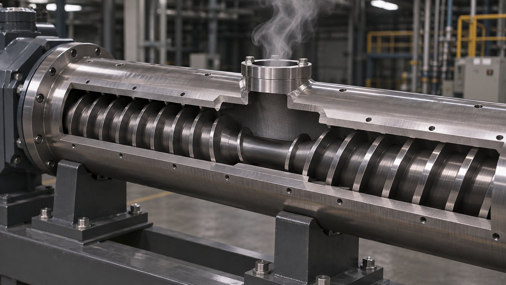
Imagine stacking two complete screws end to end on the same shaft. That is essentially what a vented two-stage screw does. The first stage melts and partially pressurizes the polymer, exactly like a conventional single-stage design. Then something unusual happens: the channel depth increases abruptly in a decompression zone, dropping melt pressure to atmospheric levels. This decompression zone aligns precisely with a vent port machined into the barrel, and through that port, volatiles escape - moisture, entrapped air, residual solvents, and low-molecular-weight species simply boil out of the depressurized melt. A second metering stage downstream re-pressurizes the now-degassed melt and pumps it toward the die.
The engineering logic is straightforward, but the execution is anything but simple. As SpiraMelt Technologies explains, the second-stage metering section must be designed to accommodate a higher output capacity than the first stage. If the second stage cannot move material away from the vent zone quickly enough, molten polymer backs up and floods the vent port - a messy, labor-intensive failure mode that can shut down a production line. Conversely, if the first stage does not fully melt the polymer before it reaches the vent, volatiles remain trapped inside solid fragments and cannot be extracted efficiently.
Several resin families benefit enormously from vented extrusion:
- ABS and PC/ABS blends - Residual acrylonitrile monomer and moisture from the SAN phase create splay and surface defects unless extracted during processing.
- Polycarbonate - Highly hygroscopic; even small amounts of absorbed moisture cause hydrolytic chain scission, reducing molecular weight and mechanical properties.
- Recycled polymers - Post-consumer and post-industrial regrind carries absorbed moisture, printing inks, adhesive residues, and decomposition byproducts that would otherwise contaminate the extrudate.
- Nylon (PA6, PA66) - Extremely hygroscopic resins that absorb 2-8% moisture by weight; vented extrusion can reduce or eliminate the need for pre-drying, saving significant energy and floor space.
Vent-port positioning must align precisely with the screw's decompression zone. Even a small axial mismatch means the melt has not fully decompressed when it reaches the port, and partially pressurized polymer will push out through the vent opening. Barrel vent-port design itself also matters: a properly engineered flow diverter inside the vent opening prevents molten resin from accumulating and plugging the port as the screw rotates. Traditional vent sections use a deep, consistent channel to maintain atmospheric pressure, but this approach creates low-flow areas where material can hang up and degrade. Modern designs incorporate multiple flights in the vent zone to separate the melt into thinner, rope-like strands with higher exposed surface area, dramatically improving volatile extraction efficiency.
One practical trade-off to keep in mind: vented screws require longer L/D ratios - typically 30:1 to 36:1 - because the decompression zone, vent section, and second-stage metering all consume axial length that would otherwise be dedicated to melting and pumping. Output per unit of screw length is inherently lower than a single-stage screw of the same diameter, so processors must weigh the benefit of inline devolatilization against the capital cost of a longer extruder. For highly hygroscopic or volatile-laden materials, the economics almost always favor vented extrusion over offline pre-drying.
Grooved-Feed Designs and Barrel Pairing Requirements
At the other end of the screw, solids conveying presents its own bottleneck. In a smooth-bore barrel, the friction between pellets and the barrel wall is what drags material forward. Increase screw speed, and you'd expect proportionally higher throughput - but in practice, at higher RPMs the pellets begin to spin with the screw rather than advancing axially. Output plateaus, and it becomes dependent on the downstream die resistance. This friction-limited conveying behavior constrains smooth-barrel systems from reaching their full throughput potential.
Grooved-feed barrels solve this problem by machining longitudinal or helical grooves into the bore of the feed section. These grooves mechanically lock pellets against the barrel wall, creating a positive-displacement-like conveying action that decouples throughput from friction conditions and, critically, from downstream back pressure. Research at the University of Stuttgart confirmed that grooved barrel extruders maintain counter-pressure-independent throughput - increasing die back pressure from 50 bar to 200 bar produced no measurable change in mass throughput when a helically grooved feed zone was used. In contrast, the same pressure increase on a smooth-barrel system caused throughput to drop by 28-48%.
The geometry of the grooves matters. Axially grooved barrels (grooves parallel to the screw axis) deliver the highest throughput at low screw speeds because of their steep solid conveying angle. Helically grooved barrels (grooves angled to follow a helical path) produce slightly lower throughput at low speeds but exhibit superior pressure stability and prediction accuracy. Interestingly, the Stuttgart research found that at high screw speeds above 800 RPM, throughput from axially and helically grooved barrels converges completely - the limiting factor shifts from groove geometry to the pellet stream entering through the hopper opening.
Pellet shape also plays a decisive role. Small, spherical granules maintain linear throughput behavior up to much higher screw speeds (1200 RPM in smooth barrels, 600 RPM in grooved barrels) before non-linear behavior sets in, compared to larger lenticular or cylindrical pellets that deviate from linear predictions at around 300 RPM. This means the same grooved-feed barrel can behave quite differently depending on the resin form factor being processed.
Here is the critical constraint: grooved-feed barrels require specific screw designs with reduced compression ratios. The mechanical locking action in the grooves generates enormous feed-zone pressures - far higher than a smooth-bore system. If you pair a grooved-feed barrel with a screw that has a standard compression ratio, the excessive pressure build-up in the feed zone can overload the drive, generate dangerous barrel pressures, and degrade the polymer through excessive compaction heat before it even reaches the transition zone. Screws designed for grooved-feed systems typically feature shallower feed channels and gentler transitions to accommodate the already-pressurized solid bed arriving from the grooved section.
Matching Screw Configuration to Barrel Specifications
Single-start vs. multi-start flight configurations add another layer of design flexibility - and another dimension of screw and barrel interdependence. A single-start (single-flight) screw has one helical flight winding along its length, producing one channel per revolution. Multi-start designs use two or more parallel flights, dividing the channel into multiple narrower passages.
Why go multi-start? Multiple flights create thinner melt layers in each channel, which improves heat transfer and reduces the distance heat must travel from the barrel wall to the channel center. This accelerates melting and improves thermal homogeneity. Multi-flight configurations also distribute the conveying load more evenly around the screw circumference, reducing deflection forces that push the screw against the barrel wall - a significant benefit for wear reduction on long-L/D extruders. The trade-off is reduced channel volume per flight, which can limit throughput capacity unless compensated by increased screw speed or diameter.
In vented extrusion, multi-start flights serve a specific additional function. Multiple narrower channels in the vent zone separate the melt into thinner strands with more exposed surface area, substantially improving volatile removal compared to a deep single-channel vent section where the polymer sits as a low-surface-area mass.
The overarching lesson across all of these specialty configurations is this: vented screws, grooved-feed screws, and multi-start designs cannot function as drop-in replacements for standard screw and barrel combinations. Each requires a barrel engineered to match - vent ports aligned to decompression zones, grooves machined into the feed section with specific depth and angle profiles, and bore tolerances held to the tighter specifications that multi-flight geometries demand. Ordering a specialty screw without specifying the barrel it must pair with is a recipe for underperformance at best and equipment damage at worst.
For extrusion manufacturers and equipment builders sourcing matched assemblies, suppliers that offer the full range of configurations under one engineering umbrella simplify the specification process considerably. NANHAIYA's single screw barrel product line, for example, covers barrier, vented, single-start, multi-start, and grooved-feeding barrel configurations designed to pair with corresponding screw types. Nitrided surface treatments and custom dimensional specifications are available for matching to existing machine platforms - a practical consideration when retrofitting older extruders with upgraded screw designs. When evaluating any supplier, the key question is whether they can confirm engineering compatibility between the screw geometry, barrel bore, vent-port placement, and feed-section configuration for your specific machine and resin combination.
Specialty single-screw configurations push the boundaries of what a single rotating shaft inside a heated cylinder can accomplish. Yet certain processing demands - reactive compounding, intensive additive incorporation, simultaneous feeding and devolatilization at multiple points - exceed even the most sophisticated single-screw architecture. Those applications require a fundamentally different machine concept: two screws turning inside a shared barrel.
Twin-Screw Extruder Types and Element Selection
Two screws turning inside a shared barrel sounds like a simple doubling of hardware - but the processing reality could not be more different. Twin-screw extruders do not merely add a second screw; they introduce entirely new flow fields, mixing mechanisms, and design philosophies that have no parallel in single-screw machines. Where a single-screw extruder relies on drag flow between the polymer, the screw channel, and the barrel wall, twin-screw systems generate interscrew interaction - material is transferred, compressed, sheared, and reoriented between the two rotating shafts in ways a solitary screw simply cannot replicate.
The most fundamental decision when specifying twin-screw equipment is rotation direction: do the two screws turn the same way, or in opposite directions? That single choice cascades through every aspect of screw element design, mixing intensity, pressure generation, and application fit. Layer on the distinction between intermeshing and non-intermeshing geometries, and the landscape of screw extruders broadens dramatically.
Co-Rotating vs. Counter-Rotating Twin-Screw Architectures
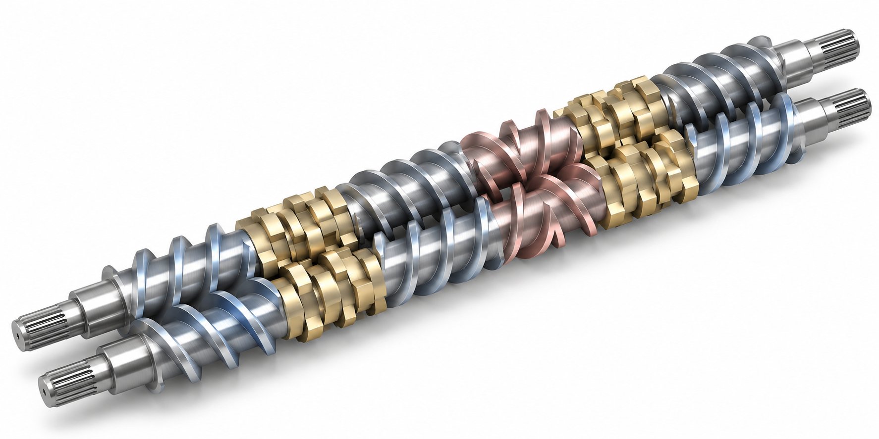
In a co-rotating twin-screw extruder, both screws turn in the same direction - typically with a fully intermeshing geometry. Imagine two gears meshing together, except instead of locking teeth they share overlapping helical flights. At the intermeshing region, material is forcibly transferred from one screw to the other, tracing a figure-eight path down the length of the barrel. This continuous hand-off creates a self-wiping action that sweeps material off screw surfaces, suppresses stagnation, and keeps the residence time distribution remarkably narrow.
The geometry behind this self-wiping behavior is known as the Erdmenger profile - a mathematically defined cross-sectional shape where the flight tip of one screw perfectly sweeps the root and flanks of the other. The result: virtually zero dead volume inside the barrel. For reactive extrusion, where even brief thermal exposure in a stagnant pocket can degrade product quality, this self-cleaning characteristic is indispensable.
Mixing in co-rotating machines is intense. High shear stress develops both between the screws and between each screw and the barrel wall. Kneading blocks add an elongational flow component on top of this shear field, imposing a complex deformation history on the polymer. You can break down filler agglomerates, control phase morphology in polymer alloys, and drive chemical reactions - all by selecting the right combination of screw elements and sequencing them along the shaft.
Counter-rotating twin-screw extruders flip the script. The two screws rotate in opposite directions, and at the intermeshing region, material is drawn inward between the screws and compressed as it advances. Think of a pair of calender rolls: polymer gets squeezed between two converging surfaces, experiencing compressive and elongational deformation rather than the aggressive shear of a co-rotating system. As Technovel's extrusion specialists explain, this calendering effect disperses additives under relatively gentle conditions - a critical advantage for thermally sensitive materials where shear-induced heat generation must be minimized.
Counter-rotating machines typically operate at higher fill ratios and lower screw speeds than their co-rotating counterparts. Material transport depends strongly on screw rotation itself, enabling stable extrusion even at speeds that would starve a co-rotating system. Rigid PVC - a resin with notoriously low thermal decomposition tolerance and poor melt flow - is the textbook application. The low-shear, low-temperature processing environment of a counter-rotating extruder keeps the material below its degradation threshold while the calendering action provides enough dispersive mixing to incorporate stabilizers and lubricants uniformly.
Modular Screw Elements and Kneading Block Configuration
Here is where twin-screw design diverges most dramatically from single-screw thinking. A single extruder screw is typically machined as one continuous piece of steel - feed zone, transition, metering section, mixing elements, all carved from the same shaft. Twin-screw machines, by contrast, use a modular building-block system. Individual screw elements slide onto a splined shaft and can be rearranged, swapped, or replaced without manufacturing an entirely new screw. This modularity lets processors build custom screw profiles element by element, tailoring each zone of the barrel to a specific processing function.
The main element categories include:
- Conveying elements - Deep-flighted helical elements that transport material forward without imparting significant shear. Larger pitch elements (e.g., SK 40/40 in Brabender nomenclature) move bulk material quickly, while smaller pitch elements (e.g., SE 20/20) compress material and build pressure. Conveying ability decreases as pitch decreases.
- Forward kneading blocks - Stacked offset discs that shear and fold the melt as it passes through. Wider discs (KBW) promote dispersive mixing through stronger shear forces, while narrower half-disc configurations (KP) lean toward distributive action. Forward-staggered blocks maintain some conveying ability while mixing.
- Neutral kneading blocks - Discs staggered at 90 degrees, which provide no forward conveying. Because material dwells longer in these elements, they are more aggressive - imparting maximum energy to the polymer and increasing residence time in the mixing zone.
- Reverse kneading blocks - Discs oriented to push material backward against the forward flow. These create maximum restriction, generating the highest shear of any element type. They are typically kept shorter than one screw diameter to prevent dangerous pressure peaks.
- Reverse screw elements - Full-flight conveying elements with left-hand pitch that slow material flow, often placed before or after kneading blocks to intensify the mixing zone by increasing local fill level and residence time.
- Toothed mixing elements - Elements with protruding teeth arranged in rows that split and recombine the melt stream. These provide distributive mixing with gentle forward conveying and are commonly placed before the compression zone to blend solid and liquid ingredients.
Building a screw profile is essentially a sequencing exercise. A typical compounding configuration might start with large-pitch conveying elements at the feed throat, transition to tighter-pitch elements as the material approaches the first kneading zone, introduce a block of forward kneading discs for initial melting and dispersive mixing, follow with reverse elements to create a melt seal before a downstream feed port, then repeat a similar mixing-conveying pattern for a second additive incorporation stage. Each element's position, width, stagger angle, and length interact with its neighbors to determine local shear rates, fill levels, and temperatures. The extrusion screw compression ratio on a twin-screw system is not a fixed number stamped on the screw - it is an emergent property of how elements are sequenced along the entire shaft.
The table below highlights the core differences between single-screw and twin-screw architectures across the features that matter most when selecting an extruder platform:
| Feature | Single-Screw | Co-Rotating Twin | Counter-Rotating Twin |
|---|---|---|---|
| Screw construction | One-piece machined shaft | Modular elements on splined shaft | Modular or one-piece, depending on application |
| Mixing intensity | Limited; relies on add-on mixing sections | High; adjustable via kneading block selection | Moderate; calendering-based dispersive action |
| Self-wiping | No | Yes (Erdmenger profile) | Partial; depends on intermeshing degree |
| Residence time distribution | Broad | Narrow and controllable | Moderate |
| Throughput vs. screw speed | Coupled (drag-flow dependent) | Partially decoupled (starve-fed operation) | Coupled at high fill; partially decoupled with gravimetric feeding |
| Feed capability | Pellets preferred; powder feeding limited | Excellent for powders, fibers, and liquids via side stuffers | Good for powders; commonly used with PVC dry blends |
| Devolatilization | Requires dedicated vented two-stage screw | Multiple vent ports easily integrated | Possible but less common |
| Shear sensitivity | Moderate shear; adjustable with screw design | High shear; risk of degradation with sensitive resins | Low shear; ideal for thermally unstable polymers |
| Typical extrusion barrels L/D | 24:1 to 36:1 | 32:1 to 52:1 | 22:1 to 34:1 |
| Capital cost | Lower | Higher | Moderate to high |
| Primary applications | Pipe, profile, blown film, sheet | Compounding, reactive extrusion, devolatilization, masterbatch | PVC pipe/profile, calender feeding, low-shear compounding |
When to Choose Twin-Screw Over Single-Screw Extrusion
With all these architectural differences on the table, the practical question becomes: when does the added complexity and cost of a twin screw and barrel system actually pay off?
The decision hinges on three drivers: mixing demand, feeding flexibility, and process control granularity.
Choose co-rotating twin-screw when the process requires intensive compounding - blending polymers with high filler loadings (glass fiber, mineral, carbon nanotube), reactive extrusion involving in-situ polymerization or grafting, or multi-stage devolatilization. The modular screw profile, self-wiping barrel, and ability to accept multiple side-feed and vent ports make co-rotating machines the default for masterbatch production, polymer alloy development, and recycling lines where contaminated streams need simultaneous melting, degassing, and filtration. Starve-fed operation - where a gravimetric feeder meters material into the extruder at a controlled rate independent of screw speed - gives processors a degree of process control that flood-fed single-screw systems simply cannot match.
Choose counter-rotating twin-screw when the resin is thermally fragile and demands low-shear processing. Rigid PVC dominates this category. The calendering action between counter-rotating screws disperses stabilizers and lubricants effectively at temperatures well below PVC's decomposition point. Profile extrusion, pipe, and sheet lines running PVC formulations overwhelmingly favor this architecture.
Stay with single-screw when the application is straightforward melting and forming - pipe, profile, blown film, cast film, wire coating, or sheet extrusion of a single resin or a pre-compounded blend. Single-screw machines cost less to purchase, operate, and maintain. They generate less specific energy input per kilogram of throughput for simple melting tasks, and their one-piece screw construction is inherently more robust against the high pressures required to push melt through restrictive dies. For the vast majority of forming operations where the polymer arrives as pre-compounded, pre-colored pellets, a well-specified single-screw extruder with the right barrier, mixing, or vented configuration delivers equivalent product quality at lower total cost.
In reality, many production lines combine both platforms. A co-rotating twin-screw compounder blends and pelletizes the formulation; a single-screw forming extruder remelts those pellets and pushes them through the die. Each machine does what it does best, and the overall line benefits from the strengths of both architectures.
Selecting the right extruder platform is only half the equation, though. Even the best-matched screw type can produce defective product if it is worn, mismatched to the resin, or fighting a barrel specification it was never designed for. Recognizing those failure modes - and tracing them back to their root cause - is what separates experienced processors from those who chase symptoms instead of solutions.
Troubleshooting Processing Problems Through Screw Type Selection
Here is something most troubleshooting guides get backward: they start with the defect and suggest tweaking process settings - temperature, screw speed, back pressure - until the symptom disappears. That approach works when the screw is correct for the application and only the process window needs tightening. But when the plastic extruder screw itself is the wrong type for the resin, no amount of parameter adjustment will deliver a lasting fix. You will chase the same defects shift after shift, burning through operator hours, scrap resin, and production schedules.
Flipping the perspective changes everything. Treat the defect as a diagnostic clue pointing toward the screw architecture that should be running in that barrel. Melt fracture, color streaks, thermal degradation, output surging - each one has a signature screw-related cause. Identify the cause, change the screw type, and the defect resolves at its root rather than being temporarily masked by a process band-aid.
Common Processing Defects Traced to Wrong Screw Type
The table below maps six of the most frequently encountered extrusion and injection molding defects to their likely screw-related cause and the design change that addresses each one. If you have been fighting any of these problems persistently, the screw type - not just the process profile - deserves scrutiny.
| Processing Problem | Likely Screw Cause | Recommended Screw Type Change |
|---|---|---|
| Melt fracture / shark skin | Excessive shear in the metering zone or mixing section; screw compression too aggressive for the resin's melt viscosity | Switch to a lower-compression screw or replace a dispersive Maddock mixer with a gentler distributive element (pin or Saxton); consider a wave screw for extensional mixing with lower peak shear |
| Poor color dispersion / streaking | Insufficient mixing capability; GP screw with no mixing section; or a barrier screw paired with no downstream distributive element | Add a dispersive mixer (Maddock) to break pigment agglomerates, followed by a distributive section (pineapple or pin mixer) to spread dispersed pigment uniformly through the melt |
| Thermal degradation / brown or black specks | Over-shearing caused by too-tight barrier clearance, aggressive kneading blocks (twin-screw), or excessive compression on a shear-sensitive resin like PVC | Reduce compression ratio; widen barrier clearance; on twin-screw systems, replace neutral or reverse kneading blocks with forward blocks or toothed mixing elements to lower residence time and peak shear |
| Output surging / pressure oscillation | Solid bed breakup in a GP screw's compression zone causing intermittent pressure spikes; or a vented screw with insufficient second-stage pumping capacity | Replace GP screw with a barrier design (Maillefer or parallel) to stabilize solids-melt separation; for vented designs, increase second-stage metering depth or add a gear pump downstream |
| Incomplete melting / unmelt specks | Insufficient compression or barrel contact area; GP screw running at speeds that exceed its melting capacity; or a screw designed for amorphous resin being used on a crystalline polymer | Move to a barrier screw with closed-end solids channel for crystalline resins; increase L/D if barrel permits; add a dispersive mixing section downstream to finish any residual unmelt |
| Feed-zone bridging / starving | Excessive feed-zone temperature causing premature pellet softening; or a grooved-feed barrel paired with a high-compression screw that generates dangerous feed-zone pressures | Reduce feed-zone barrel temperature; if grooved barrel, switch to a screw with reduced compression and shallower feed channel; for sticky resins, consider a grooved-feed barrel with proper low-compression screw to decouple throughput from friction |
Notice a pattern? Many of these defects look like process problems on the surface - common troubleshooting guides will tell you to adjust barrel temperatures, change screens, or reduce RPM. Those steps may provide temporary relief, but if the root cause is a fundamental mismatch between screw geometry and resin behavior, the defect will return the moment conditions shift even slightly. A screw type change, by contrast, widens the entire processing window so that normal run-to-run variation no longer triggers the defect.
Screw Wear Patterns and When to Replace or Redesign
Even the perfectly matched screw and barrel combination will not stay perfect forever. Wear is inevitable - and the insidious part is that a worn screw mimics the symptoms of a wrong screw type. Output drops, melt quality deteriorates, pressure fluctuates, and operators start cranking up temperatures and screw speeds to compensate. Without measuring flight clearances and channel depths, you could easily misdiagnose a wear problem as a design mismatch and order the wrong replacement.
Extruder screw wear issues fall into three distinct categories, each leaving a characteristic fingerprint on the flight surfaces:
- Pressure-induced wear from aggressive compression. When the compression rate is too high, melt gets forced downstream before enough liquid phase exists to lubricate the solid bed. The channel fills completely with solids for a split second, and instantaneous localized pressures can spike above 10,000 psi. The enormous force pushes the screw against the barrel on one side, tearing hard-surfacing material off the trailing edge of the flight. The telltale sign is a ragged, sharp lip of displaced hard surfacing extending off the back of the flight - typically over a span of just 3 to 6 flights in the early compression zone.
- Barrel misalignment wear. A barrel expands as it heats, and if downstream components or barrel supports prevent it from expanding in a straight line, the screw is forced to bend as it rotates. The resulting wear looks similar to compression-related damage but extends over a much longer section of the screw - including areas well past the compression zone where a full melt already exists. Operators may notice a higher-than-normal drive torque that mysteriously drops within hours as the flights wear to accommodate the misalignment.
- Abrasive filler wear. Glass fibers, mineral fillers like calcium carbonate and talc, and contaminated recycled streams contain particles harder than the nickel or cobalt matrix that supports wear-resistant carbides on screw flights. These particles cause millions of micro-abrasions as they are trapped between the rotating flight tip and the barrel liner. The worn surface appears almost polished and the flight edges become rounded - a distinctly different signature from the ragged, torn appearance of pressure or alignment wear. This damage concentrates in the feed and compression zones where loose fillers have not yet been incorporated into the melt.
How does wear change processing behavior? As flights lose material, the effective flight clearance increases. Leakage flow over the flights rises, pumping efficiency drops, and the effective compression ratio decreases because the metering-zone channel is now deeper than designed. MD Plastics' engineering team points out that when wear changes geometry, melting relocates downstream - and the process becomes unstable even if barrel temperatures stay normal. This is exactly why a worn screw produces symptoms identical to selecting the wrong screw type: both conditions result in insufficient compression, incomplete melting, and poor pressure stability.
Material selection for the screw and barrel dramatically influences how quickly wear progresses:
- Nitrided steel (gas or ion nitriding) - Provides a hard surface layer at relatively low cost. Adequate for unfilled commodity resins and moderate production volumes. Typical case depths of 0.2-0.5 mm mean the hardened layer can wear through on abrasive compounds within months.
- Bimetallic barrels with tool-steel or tungsten-carbide liners - The industry standard for filled compounds. A centrifugally cast liner of boron-carbide or tungsten-carbide alloy resists abrasive wear far longer than nitrided surfaces. Pair with a tool-steel screw (D2 or CPM-9V) or a screw with Colmonoy, Stellite, or laser-clad flight tips for maximum service life.
- Powdered metallurgy (PM) tool steels - Screws machined from CPM-10V or similar PM grades offer excellent resistance to both abrasive and adhesive wear. These are the go-to choice for highly filled engineering compounds where glass-fiber content exceeds 30% by weight.
A practical rule of thumb: if flight clearance has increased by more than 50% over the original specification, the screw's pumping and compression behavior has shifted enough to affect product quality. At that point, re-chroming or re-building the flights may restore geometry temporarily, but if the wear was caused by an inherent mismatch - abrasive fillers on a nitrided screw, or excessive compression on a soft resin - the same wear will recur on the same timeline. Addressing the root cause often means upgrading both screw metallurgy and geometry simultaneously.
Avoiding the Most Common Screw Selection Mistakes
Years of troubleshooting calls, returned screws, and post-mortem analyses reveal the same handful of selection errors appearing repeatedly across the industry. Avoiding these mistakes is often more valuable than choosing the theoretically optimal screw, because a reasonable choice executed correctly will always outperform a perfect choice undermined by one of these pitfalls.
- Using a general-purpose screw for crystalline polymers at high output rates. GP screws lack the solids-melt separation that crystalline resins (PE, PP, nylon, PET) need for clean melting at elevated screw speeds. The result is solid bed breakup, unmelt, and output surging. A barrier screw - Maillefer for lower-energy resins, parallel for higher-energy grades - resolves all three problems simultaneously.
- Over-shearing PVC with aggressive mixing elements. PVC has an extremely narrow processing window between gelation and thermal decomposition. Installing a Maddock mixer, tight-clearance barrier flight, or high-compression screw generates enough shear heat to push the resin past its degradation threshold. Counter-rotating twin-screw systems or single screws with gentle compression and distributive-only mixing elements are the safe path.
- Ignoring vent requirements for hygroscopic resins. Running nylon, PC, ABS, or recycled polymers on a single-stage screw without devolatilization forces you to rely entirely on pre-drying - an energy-intensive, time-consuming step that still leaves residual moisture. A vented two-stage screw paired with a properly positioned barrel vent port eliminates or drastically reduces pre-drying needs while improving melt quality.
- Mismatching grooved-feed barrels with standard-compression screws. Grooved feed sections generate far higher feed-zone pressures than smooth bores. Pairing them with a screw designed for smooth-bore conveying creates dangerous pressure peaks, excessive compaction heat, and potential drive overloads. Always specify a reduced-compression screw geometry when running grooved-feed barrel configurations.
- Pairing a barrier screw with a dispersive mixer when a distributive mixer would suffice. If the barrier section completes melting effectively, adding a high-shear Maddock element downstream is redundant - it raises melt temperature, reduces throughput through added pressure drop, and increases energy costs without improving product quality. A pin or Saxton mixer handles temperature homogenization and additive distribution with far less thermal penalty.
- Blaming the screw design when the real problem is wear. A worn screw with increased flight clearance and reduced effective compression mimics the symptoms of a wrong screw type - poor melting, surging, and temperature inconsistency. Always measure flight diameters and channel depths before concluding that a design change is needed. Replacing a worn screw with the same geometry in the correct metallurgy may be all the situation requires.
Every one of these mistakes stems from the same underlying oversight: treating the screw as an isolated component rather than as one half of an engineered screw and barrel system matched to a specific polymer, filler package, and throughput target. The final section of this article brings all the variables together into a structured selection framework - a step-by-step decision process that connects resin properties, processing goals, and machine specifications to the right screw architecture.
How to Choose the Right Extruder Screw Type for Your Application
Knowing the technical differences between barrier screws, wave architectures, vented two-stage designs, and twin-screw configurations is valuable - but knowledge alone does not put the right screw in your barrel extruder. What processors and equipment builders actually need is a repeatable decision process that translates resin data, product requirements, and machine constraints into a specific screw design recommendation. That is exactly what this section delivers.
Think of screw selection as a funnel. You start with broad variables - polymer family, processing goal, filler package - and progressively narrow the options until only one or two architectures remain viable. Skip a step, and you risk the kind of mismatch errors described in the troubleshooting section: general-purpose screws running crystalline resins at high speed, dispersive mixers torturing shear-sensitive PVC, or vented screws orphaned from barrels that lack vent ports. The framework below keeps those mistakes out of the picture from the start.
Step-by-Step Screw Type Selection Decision Process
Follow these steps in sequence. Each one eliminates options that do not fit your situation, so by the time you reach the final step, the field of candidates is already small and manageable.
- Identify the polymer family and its melting behavior. Is the resin crystalline (PE, PP, nylon, PET, PBT) with a sharp melting point, or amorphous (PC, ABS, PS, PMMA) with a gradual softening range? Crystalline resins benefit from barrier screw designs that exploit the well-defined solid-melt boundary. Amorphous and shear-sensitive resins often perform better on general-purpose screws with appropriate mixing sections, or on counter-rotating twin-screw systems for thermally fragile formulations like rigid PVC.
- Determine the primary processing goal. Are you forming a product (pipe, profile, film, sheet, wire coating) or compounding a formulation (blending polymers, incorporating fillers, reactive extrusion)? Forming operations favor single-screw extruders for their cost efficiency and pressure-generation capability. Compounding, masterbatch production, and reactive processing favor co-rotating twin-screw systems for their modular mixing flexibility and multi-port feeding capability.
- Assess filler, additive, and volatile requirements. High filler loadings (above 30% glass fiber or mineral) almost always demand twin-screw compounding. Moderate additive levels (color concentrates, stabilizers, processing aids) can be handled by single-screw machines equipped with the right mixing sections. Hygroscopic resins or recycled feedstocks carrying moisture and volatiles point toward vented two-stage screw designs - or co-rotating twin-screw systems with integrated vent ports for more aggressive devolatilization.
- Evaluate throughput and quality targets. If you need maximum output at high screw speeds, barrier screws (particularly parallel or MC3 variants) outperform general-purpose designs because they maintain melt quality as speed increases. If optical clarity, surface finish, or tight dimensional tolerances are the priority, wave screws or barrier-plus-distributive-mixer combinations offer superior melt homogeneity. For shot-to-shot consistency in injection molding, screws with mixing sections are essential regardless of resin type.
- Check the existing machine specifications. What is the barrel's L/D ratio? Does it have vent ports? Is the feed section smooth-bore or grooved? A vented screw requires a barrel with a properly positioned vent port. A grooved-feed screw requires a barrel with machined grooves and intensified cooling in the feed section. Retrofitting a barrier screw into an existing smooth-bore barrel is often straightforward - but swapping in a vented or grooved-feed design without the matching barrel is not an option. Always confirm mechanical compatibility before finalizing the screw design.
- Select the screw metallurgy and surface treatment. Match wear protection to the actual threat. Unfilled commodity resins run well on nitrided steel. Abrasive fillers (glass fiber, calcium carbonate, wood flour) require bimetallic barrels and tool-steel or carbide-tipped screw flights. Corrosive resins (PVC, fluoropolymers) need chrome plating or nickel-alloy protection. Selecting the right metallurgy at the outset prevents the premature wear cycle that mimics wrong-type screw selection and forces unnecessary redesigns.
- Validate with a trial or simulation. Even the best engineering analysis benefits from confirmation. Run a short production trial at target speed and throughput, monitoring melt temperature, head pressure, motor load, and product quality. Compare measured values against predictions. If any parameter falls outside the acceptable window, revisit the screw design - the selection framework above will help you identify which variable changed and which design adjustment corrects it.
Master Comparison of All Major Extruder Screw Types
The table below consolidates every screw architecture covered in this article into a single reference. Use it alongside the decision steps above to cross-check your selection against the design features, material compatibilities, and application profiles of each type. No single row is universally "best" - the right choice always depends on the intersection of your resin, your product, and your machine.
| Screw Type | Key Design Feature | Best-For Materials | Mixing Capability | Output Rate | Melt Homogeneity | Shear Level | Typical Applications |
|---|---|---|---|---|---|---|---|
| General-Purpose (3-Zone) | Single flight with feed, compression, and metering zones | Amorphous resins (PS, ABS); low-speed commodity extrusion | Low - no dedicated mixing | Moderate; limited by solid bed breakup at high RPM | Fair; temperature gradients across channel width | Moderate | Basic pipe, profile, sheet, wire coating |
| Barrier - Maillefer | Crossing barrier flight; constant-width solids channel | LDPE, LLDPE, PP copolymers, soft or slippery resins | Low - requires downstream mixer | Good; stable melting at elevated speeds | Good; controlled solids-melt separation | Moderate | Blown film, cast film, flexible packaging |
| Barrier - Parallel (Barr) / MC3 | Parallel barrier flight; narrowing solids channel; MC3 adds extended lead for higher volume | HDPE, nylon, PET, high-energy crystalline resins | Low - requires downstream mixer | High; ~33% more melting area than Maillefer per unit length | Very good; maximizes barrel-side melting contact | Moderate to high | HDPE pipe, PP sheet, high-output blown film |
| Wave Screw | Oscillating channel depth in metering zone creates extensional flow | PE, PP, and other polyolefins for film and sheet | Good distributive; extensional flow improves homogeneity | High; dampens pressure surges | Excellent; reduces melt temperature variation | Low to moderate | Blown film, cast film, sheet extrusion requiring tight gauge control |
| Pin Mixing Screw | Cylindrical pins protruding from screw root split and recombine melt | Pre-compounded blends; masterbatch let-down; heat-sensitive resins | Strong distributive; low dispersive | Moderate; pins create pressure drop | Very good for blending; limited agglomerate breakup | Low | Color blending, additive incorporation, PVC stabilizer distribution |
| Maddock Mixer Section | Fluted barrier element forces melt over narrow clearance gap | Resins requiring pigment or gel dispersion; recycled streams with agglomerates | Strong dispersive; moderate distributive | Slight reduction due to restriction | Good for breaking agglomerates; raises melt temperature | High | Color-critical extrusion, recycled-resin processing, injection molding |
| Vented Two-Stage | Decompression zone aligned with barrel vent port; second metering stage re-pressurizes | ABS, PC, nylon, PET, recycled polymers - any hygroscopic or volatile-laden resin | Depends on added mixing sections | Lower per unit L/D than single-stage; 30:1-36:1 L/D typical | Good; devolatilization removes bubbles and moisture defects | Moderate | Sheet, film, and profile from hygroscopic or recycled resins; drying-free processing |
| Grooved-Feed | Barrel grooves mechanically lock pellets; pressure-independent solids conveying | HMW-HDPE, UHMWPE, and resins where friction-limited feeding caps throughput | Depends on downstream screw geometry | Very high; throughput independent of back pressure | Good; lower melt temperature for given output | Moderate; reduced compression needed | High-output HDPE pipe, blown film, high-viscosity extrusion |
| Co-Rotating Twin | Intermeshing self-wiping screws; modular elements on splined shafts | Filled compounds, polymer blends, masterbatch, reactive systems | Excellent; fully adjustable via kneading block selection | High; starve-fed operation decouples feed from screw speed | Excellent; narrow residence time distribution | High; tunable with element selection | Compounding, masterbatch, reactive extrusion, devolatilization |
| Counter-Rotating Twin | Opposing rotation with calendering action between screws | Rigid PVC, thermally sensitive formulations, low-shear compounds | Moderate dispersive via calendering; good distributive | Moderate; positive displacement at low RPM | Good; stable melt temperature | Low | PVC pipe, window profiles, siding, calender feeding |
A few patterns worth highlighting. Barrier and vented designs appear across the widest range of commodity and engineering polymers - PE, PP, nylon, PET, ABS, PC, recycled streams. If your operation processes multiple resin families, these two architectures (sometimes combined on the same screw) offer the broadest coverage. Wave screws occupy a narrower niche but deliver outsized value in film and sheet applications where gauge uniformity is the primary quality metric. And twin-screw systems, while more expensive, remain irreplaceable for any process that involves true compounding rather than simple melting and forming.
Sourcing Extruder Screws and Barrels for Custom or Replacement Needs
Selecting the right screw design on paper is only the beginning. Translating that selection into a physical component that fits your machine, matches your barrel bore, and delivers the expected performance requires careful sourcing - whether you are ordering an OEM replacement, upgrading an existing line, or specifying components for a new build.
Three sourcing scenarios cover most real-world situations:
- OEM replacement. You are replacing a worn screw with the same geometry and metallurgy. The critical requirement is dimensional accuracy - flight OD, root diameters, channel depths, and overall length must match the original specification within tight tolerances. Request the manufacturer's original drawing if available, or have the worn screw measured professionally before ordering.
- Aftermarket upgrade. You are switching from a general-purpose screw to a barrier, vented, or wave design on an existing machine. This is where engineering confirmation becomes essential. The new screw design must be compatible with the existing barrel's L/D, bore diameter, vent-port positions (if any), and feed-section configuration (smooth vs. grooved). Upgrading the screw without verifying barrel compatibility is the single most common sourcing mistake in the industry.
- New-build specification. You are specifying extruder screws and barrels for a new production line. This scenario offers the most design freedom but also requires the most complete input data: polymer family, filler package, throughput target, die resistance, melt temperature limits, and product quality requirements. Work with the screw manufacturer's engineering team to select geometry, compression ratio, mixing elements, and metallurgy as an integrated package.
Regardless of scenario, several practical considerations apply universally. Confirm that the supplier manufactures both screws and barrels - or at minimum guarantees dimensional compatibility between the screw they produce and the barrel it will operate in. Verify that surface treatments (nitriding, bimetallic liners, chrome plating, carbide hardfacing) are matched to the resin and filler system, not defaulted to the cheapest option. And document everything: screw design specifications, barrel dimensions, operating parameters, and wear measurements at installation. That documentation becomes invaluable when troubleshooting future issues or ordering the next replacement.
For extrusion manufacturers and equipment builders seeking a single source for matched screw-barrel assemblies, NANHAIYA's single screw barrel product line covers barrier, vented, single-start, multi-start, and grooved-feeding configurations designed to pair with corresponding screw types. Nitrided and other surface-treatment options are available, and custom or replacement manufacturing can be reviewed alongside your existing machine specifications and conveying requirements. As with any supplier, the value lies in engineering confirmation - ensuring that screw geometry, barrel bore, vent-port placement, and feed-section configuration are verified as compatible for your specific application before production begins.
Ultimately, the right extruder screw type is the one matched to your resin's melting behavior, your product's quality demands, your filler system's wear profile, and your barrel's physical specifications. Use the decision framework and comparison table in this section as your starting point, validate with your process data, and confirm engineering compatibility with your component supplier. That disciplined approach - resin first, geometry second, metallurgy third, supplier confirmation last - is what separates processors who solve problems permanently from those who chase the same defects year after year.
Frequently Asked Questions About Extruder Screw Types
1. What are the main types of extruder screws?
The main extruder screw types include general-purpose three-zone screws, barrier screws (Maillefer, parallel/Barr, and MC3 variants), wave screws with oscillating channel depths, pin and Maddock mixing-section screws, vented two-stage screws for devolatilization, and grooved-feed designs for pressure-independent conveying. Twin-screw extruders add co-rotating intermeshing and counter-rotating architectures, each using modular elements like conveying flights, kneading blocks, and reverse elements. Selection depends on polymer melting behavior, filler content, throughput targets, and whether the application involves forming or compounding. Suppliers such as NANHAIYA offer barrier, vented, single-start, multi-start, and grooved-feeding configurations that can be matched to specific machine platforms and resin requirements.
2. What is the difference between a barrier screw and a general-purpose screw?
A general-purpose screw uses a single flight with feed, compression, and metering zones where solids and melt share the same channel. This can lead to solid bed breakup, uneven melting, and output surging at higher screw speeds. A barrier screw adds a secondary flight with reduced clearance that physically separates molten polymer from the remaining solid bed. Melt passes over the barrier flight into a dedicated melt channel while solids stay confined, ensuring progressive and controlled plastication. Barrier screws excel with semicrystalline resins like PE, PP, and nylon that have a distinct melting point, delivering more uniform melt temperature and higher usable output rates than GP designs running the same polymers.
3. How do I choose between a single-screw and twin-screw extruder?
The choice depends on processing complexity. Single-screw extruders are cost-effective for straightforward melting and forming operations such as pipe, profile, blown film, and sheet extrusion using pre-compounded pellets. Co-rotating twin-screw extruders are preferred when the process requires intensive compounding, high filler loadings above 30%, reactive extrusion, or multi-stage devolatilization, because their modular screw elements and self-wiping barrel geometry enable precise control over mixing intensity and residence time. Counter-rotating twin-screw machines suit thermally sensitive resins like rigid PVC, where low-shear calendering action prevents degradation. Many production lines combine both platforms, using a twin-screw compounder to formulate pellets that a single-screw forming extruder then reshapes.
4. When should I use a vented two-stage extruder screw?
Vented two-stage screws are ideal for processing hygroscopic or volatile-laden resins where moisture, trapped air, or residual monomers must be extracted from the melt before it reaches the die. Common candidates include nylon (PA6, PA66), polycarbonate, ABS, PC/ABS blends, and recycled polymers carrying absorbed moisture or decomposition byproducts. The screw uses a decompression zone aligned with a barrel vent port so volatiles escape at atmospheric pressure, then a second metering stage re-pressurizes the degassed melt. Vented extrusion can reduce or eliminate energy-intensive pre-drying steps. However, the screw requires a barrel with a precisely positioned vent port and typically needs a longer L/D ratio of 30:1 to 36:1 to accommodate the additional stages.
5. How does screw wear affect extrusion performance and when should a screw be replaced?
Screw wear increases flight clearance, reduces pumping efficiency, and lowers the effective compression ratio. These changes cause symptoms that mimic a wrong screw type selection - incomplete melting, output surging, temperature inconsistency, and poor product quality. Three primary wear mechanisms exist: pressure-induced wear from aggressive compression, barrel misalignment wear that spans long screw sections, and abrasive filler wear from glass fiber or mineral particles. A practical replacement threshold is when flight clearance exceeds 50% above the original specification. Nitrided steel suits unfilled commodity resins, while bimetallic barrels paired with tool-steel or carbide-tipped screws are necessary for abrasive filled compounds. Always measure flight diameters and channel depths before concluding a design change is needed.
Written by
Nanhaiya Technical Team
Zhoushan Nanhaiya Plastic Machinery Co., Ltd.
The Nanhaiya technical team supports screw and barrel manufacturing projects through application review, technical communication, custom manufacturing coordination, and production and quality control.
Discuss Your Application
Related Articles
More insights on screw barrel technology and plastics processing.
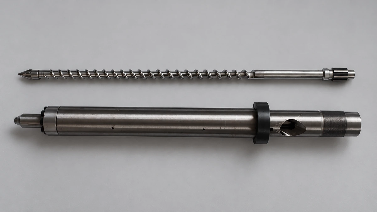
Stop Blaming The Resin: Your Injection Molding Screw Design Is Wrong
Nov 16, 2026
Learn how injection molding screw design controls melt quality. Covers L/D ratio, compression ratio, flight geometry, screw types, polymer matching, and wear.
Read Article
Carbon Black Dispersion Fundamentals Every Formulator Gets Wrong
Nov 10, 2026
Learn why carbon black dispersion fails and how to fix it. Grade selection, dispersant chemistry, equipment, QC testing, and stability — all in one guide.
Read Article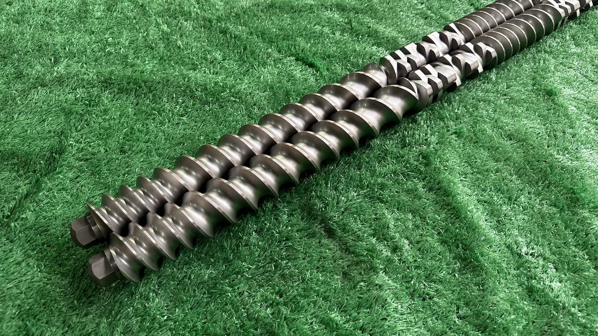
Extrusion Mixing: Why Your Screw Configuration Still Falls Short
Nov 9, 2026
Learn how extrusion mixing works, from distributive vs dispersive mechanisms to kneading block geometry, screw configuration, and SME-based quality monitoring.
Read ArticleLooking for something else?
Search by material, symptom or product and jump straight to the relevant page.
These are navigation suggestions based on keyword matching — not a quotation, not a delivery commitment, and not a substitute for engineering review. Final specification is confirmed by our engineers against your drawings and processed material.
Need help with screw barrel selection?
Share your machine model, processed material and application. Our team can help with pricing and technical support.