

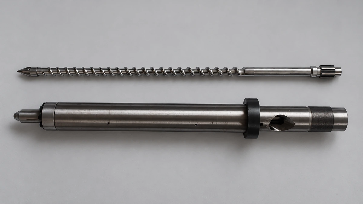
What Injection Molding Screw Design Controls and Why It Matters
Imagine this: your melt temperatures swing from shot to shot, cushion positions drift, and rejected parts pile up at the end of the line. The resin supplier insists the material is in spec. The mold has been validated. The process sheet hasn't changed. So what's left? In a surprising number of cases, the root cause is hiding in plain sight inside the barrel — a screw geometry that simply doesn't match the polymer being processed or the process window the application demands.
Injection molding screw design is the engineering discipline of specifying a screw's L/D ratio, compression ratio, flight depth, helix angle, and zone proportions so that it can convey, compress, and meter resin into a uniform, thermally homogeneous melt. Every dimension on that rotating shaft determines how efficiently solid pellets transform into pressurized, defect-free material ready for the mold cavity. Quality-management research from ASQ consistently shows that many manufacturers lose 10-15% of operating costs to poor quality — scrap, rework, warranty claims — and a mismatched screw is one of the fastest paths to inflating those numbers.
Yet most facilities still run general-purpose screws long past the point where an application-specific geometry would pay for itself. The screw is the single most influential component in the plasticizing unit, and treating it as a commodity part is one of the most expensive oversights a molding operation can make.
Why Screw Geometry Is the Largest Lever in Melt Quality
A single injection molding machine screw design must simultaneously perform five distinct functions: solid conveying, melting, melt conveying, mixing, and pressure generation. Each of these tasks is governed by geometric choices — channel depth in the feed zone controls pellet intake volume, the decreasing depth through the transition zone dictates how aggressively the material compresses and melts, and the shallow, constant-depth metering zone homogenizes temperature while building the pressure needed to push melt through the non-return valve. Change one dimension, and the balance among all five functions shifts. That's why a feed screw design for injection molding that works beautifully with polypropylene can produce unmelts in nylon or degrade PVC within minutes.
The higher the compression ratio, the greater the shear heat imparted to the resin and the better the melt uniformity — but push it too far, and you'll overheat sensitive polymers or introduce excessive stress into molded parts. It's always a set of trade-offs, and the right answer depends entirely on the specific resin, filler package, shot size, and cycle-time target you're working with.
Who This Guide Serves and How to Use It
This article is structured as a layered resource — foundational principles first, then advanced optimization — so both new process technicians and senior engineers can find actionable value. Here's a quick map to help you jump directly to the section most relevant to your role:
- Process Engineers and Technicians: Start with the zone-by-zone anatomy lesson and critical design parameters (Sections 2 and 5) to build or refresh your understanding of how flight geometry drives melt behavior.
- Tooling and Engineering Managers: Focus on screw types beyond the GP design, material-specific geometry guidance, and the decision framework (Sections 3, 4, and 8) to evaluate whether your current screws match your resin portfolio.
- Procurement and Operations Leaders: The sections on screw metallurgy, non-return valve selection, and the total-cost-of-ownership closing (Sections 6, 7, and 9) connect hardware choices directly to maintenance budgets, scrap costs, and machine uptime.
Every section builds on the one before it, but each stands on its own as a reference you can return to. The goal isn't just theory — it's giving you the specific parameters, comparison tables, and workflow steps that turn screw selection from guesswork into engineering.
Feed, Transition, and Metering Zones Explained
Every injection mold screw design splits the shaft into three functional zones, each responsible for a different stage of the pellet-to-melt transformation. Think of it like a three-act story: the feed zone ingests raw material, the transition zone melts it under pressure, and the metering zone polishes the melt into a uniform, pressurized stream. Get the proportions or depths wrong in any act, and the whole performance falls apart — unmelts, shear burns, inconsistent shots, or all three at once.
Understanding what each zone does, and which geometric levers control it, is the foundation for every screw specification decision that follows. Whether you're reviewing an OEM injection molding screw design that shipped with the machine or evaluating an upgrade, these principles apply universally.
Feed Zone Geometry and Solids Conveying
The feed zone is where solid pellets first enter the screw channel from the hopper. Its job sounds simple — grab pellets and push them forward — but the physics are anything but trivial. Channel depth here is the deepest it will be anywhere on the screw, and that depth directly controls how much material the screw ingests per revolution. A deeper channel accepts a greater volume of pellets per turn, which raises potential throughput but also demands more energy downstream to melt and compress that material.
Why does feed-zone length matter so much? Because different resins arrive at the screw with very different bulk densities. A low-bulk-density regrind or a fluffy pellet blend needs more screw length to compact and convey the same mass of material that a dense, uniformly sized virgin pellet achieves in fewer turns. If the feed zone is too short for the resin's bulk density, the screw starves — recovery time increases, and shot weights drift.
The barrel's feed throat also plays a critical supporting role here. A smooth-bore feed throat relies on the friction differential between the barrel wall and the screw root to push pellets forward. This works well for most commodity and engineering resins. A grooved feed throat, by contrast, uses machined longitudinal grooves in the barrel liner to mechanically lock pellets and force them forward with significantly higher conveying efficiency. As Davis-Standard's case-study data on HDPE processing illustrates, grooved-feed designs can achieve higher output rates at lower melt temperatures compared to smooth-bore equivalents — but they also generate higher barrel pressures and require screw geometries specifically matched to that aggressive conveying behavior. You can't simply drop a grooved feed section onto a machine and keep the same screw; the two must be engineered together.
Transition Zone and the Compression Ratio
The transition zone — sometimes called the compression zone — is where most of the actual melting happens. Here, the channel depth gradually decreases from the deep feed dimension to the shallow metering dimension. That taper compresses the material, squeezing out trapped air and forcing the developing melt film against the hot barrel wall, where conduction and viscous shear heat combine to finish the phase change from solid to liquid.
The ratio of feed-zone channel depth to metering-zone channel depth defines the compression ratio. For example, if the feed depth is 6 mm and the metering depth is 2 mm, the compression ratio is 3.0:1. This single number tells you how aggressively the screw compacts and shears the resin through the transition.
Here's where many problems originate. A compression ratio that's too high for a given polymer forces excessive shear into the melt, generating frictional heat faster than barrel cooling can remove it. The result? Localized overheating, degradation, and — in shear-sensitive resins like PVC — outright chemical decomposition. Conversely, a compression ratio that's too gentle leaves pockets of unmelted pellets ("unmelts") that pass into the metering zone and eventually through the non-return valve into the mold cavity, showing up as surface defects or weak spots in the finished part.
Semi-crystalline polymers with sharp melting points and high heats of fusion, such as nylon and POM, generally demand higher compression ratios and longer transition zones to supply enough energy for complete melting. Amorphous resins like polycarbonate and ABS soften more gradually and tolerate moderate compression. Matching this zone's taper to the polymer's solid-bed-to-melt-pool behavior is one of the most consequential decisions in any injection molding machine screw design.
Metering Zone and Melt Uniformity
By the time material reaches the metering zone, it should be fully molten — but "fully molten" doesn't automatically mean "uniform." Temperature gradients, viscosity differences, and remnants of the solid-bed structure can still exist. The metering zone's constant, shallow channel subjects the melt to a consistent shear rate that blends these variations into a thermally and compositionally homogeneous stream.
Equally important, the metering zone is where final pressure builds. The shallow channel restricts flow, generating the head pressure needed to push melt through the non-return valve and nozzle into the mold. If the metering zone is too short or too deep, pressure generation falls off, and the screw can't fill the mold reliably. If it's too long or too shallow, residence time increases and backpressure climbs — both of which raise degradation risk for heat-sensitive materials.
The metering zone typically occupies about 20-25% of total screw length on a general-purpose design, though this proportion shifts for specialized architectures. Its channel depth, combined with screw speed and backpressure settings, determines the effective output rate and the thermal quality of every shot.
Zone-by-Zone Reference Comparison
The table below maps each zone to its primary function, typical length proportion, and the key geometric parameters that an engineer or technician should evaluate when reviewing an injection molding screw design — whether from an existing machine data sheet or a new screw specification PDF.
| Zone | Primary Function | Typical Length (% of Screw) | Channel Depth | Flight Width | Helix Angle |
|---|---|---|---|---|---|
| Feed | Solids conveying and compaction; accepts pellets from hopper and moves them forward | 50-60% | Deepest (sets intake volume per revolution) | Standard (~10% of screw diameter); wider flights reduce leakage flow | Typically 17.66° (square pitch); steeper angles increase conveying rate |
| Transition (Compression) | Melting and compression; decreasing depth compacts material and drives phase change | 20-30% | Gradually decreasing from feed depth to metering depth (defines compression ratio) | Standard; flight clearance must remain tight to prevent solid-bed leakage | Same as feed zone on most GP screws; barrier designs introduce a secondary flight at a different angle |
| Metering | Melt homogenization and pressure generation; delivers uniform melt to non-return valve | 20-25% | Shallowest and constant (determines shear rate and output pressure) | Standard; some designs widen slightly to increase pressure capability | Typically 17.66°; slight deviations used to fine-tune output vs. pressure balance |
Notice how the feed zone dominates total screw length. That long conveying section is necessary to handle the wide range of pellet bulk densities and thermal properties that a general-purpose screw encounters. Specialized screws — barrier designs, vented two-stage configurations — redistribute these proportions to better match specific polymer families, a topic that reveals why a single GP screw can't serve every resin equally well.
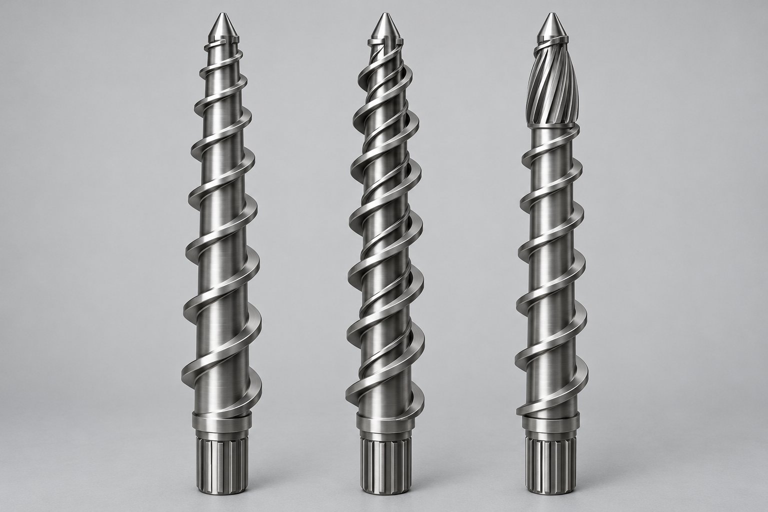
Injection Molding Screw Designs Beyond the General-Purpose Layout
That long feed zone on a general-purpose screw handles a wide range of pellet types — but "handles" isn't the same as "optimizes." When your resin portfolio grows beyond basic commodity grades, a one-geometry-fits-all approach starts costing you money in ways that don't always show up on a single line item. Longer cycles, higher scrap rates, unmelts buried inside parts, excessive purge time between color changes — these are all symptoms of a screw architecture that has hit its ceiling. The question isn't whether specialized injection molding screw designs exist. It's whether you've matched the right one to your application.
General-Purpose Screws and Their Limits
The classic GP screw uses a 50-25-25 or 50-30-20 zone-length split (feed-transition-metering), with a single continuous flight running from shank to tip. It's the screw most machines ship with, and for good reason: it processes a broad range of commodity resins — PP, PE, general-grade ABS — acceptably well. If you're molding unfilled polyolefins with generous process windows, a GP screw will get parts out the door.
The trouble begins when "acceptably" isn't good enough. As veteran injection molding consultant John Bozzelli has pointed out, the GP screw's transition zone is where its fundamental weakness lives. The single-flight design allows the developing solid bed to break apart before it fully melts. Fragments of unmelted resin drift into the melt pool, creating temperature non-uniformity and, ultimately, defects in the finished part. Bozzelli's field research documented that roughly 80% of machines running GP screws exhibit some degree of solid-bed breakup and polymer degradation at the flight-root junction — problems that cascade into weaker weld lines, warp, color marbling, and extended color-changeover times.
GP geometry becomes an even sharper bottleneck with:
- Shear-sensitive polymers (PVC, certain TPEs) that degrade when the single-flight compression zone generates uneven local shear.
- Semi-crystalline resins with sharp melt points (nylon, POM, PBT), where the narrow energy window between "still solid" and "fully molten" demands more controlled melting than a simple channel-depth taper provides.
- Highly filled compounds (glass-fiber, mineral-loaded grades), where the GP transition zone's geometry can't adequately distribute fillers without either breaking fibers or leaving pockets of poor dispersion.
Recognizing these limits is the first step toward asking a better question: which screw architecture actually fits the polymer and the process target?
Barrier Screws for Improved Melting Efficiency
Imagine a wall running down the middle of the transition zone, physically separating the shrinking solid bed on one side from the growing melt pool on the other. That's essentially what a barrier screw does. A secondary flight — the barrier flight — is introduced alongside the primary flight, creating two distinct sub-channels: a solids channel and a melt channel. As the solid bed melts, the liquid fraction is forced over the barrier flight (which has a slightly smaller clearance than the primary flight) and into the melt channel. This prevents the solid bed from fracturing and contaminating the melt pool, a problem that plagues every GP screw.
The result is a more consistent melt temperature and fewer unmelts reaching the metering zone. Barrier designs are common upgrades for processing PE, PP, and nylon — resins where throughput demands and melt-quality requirements justify the added screw complexity. For an injection molding screw design for nylon, where the sharp crystalline melt point punishes inconsistent melting, a barrier flight can significantly tighten the melt-temperature spread from shot to shot.
Barrier screws do carry trade-offs, however. The narrower sub-channels increase the screw's sensitivity to wear — as flight lands erode, barrier clearance opens and the separation between solid and melt degrades. Bozzelli's purging tests also revealed that polymer can stagnate within barrier flights and darken over time, producing degradation and black specks that undermine the very quality improvement the barrier was supposed to deliver. This doesn't disqualify barrier screws, but it does mean they require more disciplined maintenance and more frequent inspection than GP geometry.
Mixing Sections — Dispersive and Distributive
Sometimes the bottleneck isn't melting efficiency — it's mixing. Color concentrates streak. Additive packages clump. Glass fibers bunch together instead of distributing evenly. These are mixing deficiencies, and they call for specialized screw elements added to (or integrated into) the metering zone.
Mixing in a screw channel falls into two categories, and understanding the difference is critical for selecting the right element.
Dispersive mixing applies high shear stress to break down agglomerates — clumps of pigment, filler clusters, or gels that need to be physically torn apart. The Maddock (or LeRoy) mixer is the classic dispersive element. It forces melt through a narrow clearance gap between fluted channels, subjecting every fluid element to intense shear. If your problem is undispersed carbon black or pigment agglomerates, a Maddock-type section is typically the first intervention an experienced screw designer will recommend.
Distributive mixing, by contrast, re-orients and recombines melt streams without subjecting them to extreme shear. Saxton-type mixers, pineapple mixers, and pin-mixing sections all work this way — they repeatedly split, fold, and recombine the melt to spread minor-phase components (color, additives, low-concentration fillers) uniformly throughout the matrix. As extrusion mixing research from Technovel explains, distributive action relies on strain — dividing and recombining flow streams — while dispersive action relies on stress to break cohesive clusters apart. Balancing these two actions properly yields a compound with both fine particle size and uniform spatial distribution.
You'll notice that many real-world screws combine both types. A Maddock section near the end of the metering zone handles agglomerate breakup, followed by a short distributive pin section that homogenizes the final melt. The specific combination depends on the polymer, the additive package, and the defect you're trying to eliminate. Shear-sensitive materials like certain thermoplastic elastomers benefit from distributive-only mixing, while heavily pigmented compounds may need aggressive dispersive elements to eliminate visible specks.
Vented and Two-Stage Screws
What happens when the resin carries moisture or trapped volatiles that can't be fully removed by pre-drying alone? Hygroscopic polymers like nylon absorb atmospheric moisture rapidly — even properly dried pellets can regain moisture during transfer from the dryer to the feed throat. Volatile contaminants in recycled resins present a similar challenge. In these situations, a two-stage (vented) screw becomes necessary.
A two-stage screw is essentially two screws in series on a single shaft. The first stage — feed, transition, and metering — melts and compresses the resin just like a conventional single-stage design. Then the channel depth abruptly increases in a decompression zone, dropping the melt pressure to near zero and exposing a large surface area of molten polymer. A vent port in the barrel at this location allows steam, volatile gases, and trapped air to escape — either to atmosphere or under vacuum. Downstream, the second metering stage recompresses the melt and builds the pressure needed for injection.
The geometry of that decompression zone is critical. If it doesn't drop pressure fast enough, melt floods the vent and polymer oozes out of the port — a frustrating condition called vent flow. If the recompression section can't generate enough pressure to push melt through the nozzle, shot weights suffer. As devolatilization research published by Plastics Technology emphasizes, the upstream and downstream seals must be carefully designed so that changes in screw speed or throughput don't destabilize the vent zone and cause flooding or loss of vacuum integrity.
Two-stage screws are longer than single-stage equivalents — typically requiring 24:1 or greater L/D ratios to fit both stages — so they aren't a drop-in replacement on every machine. They also demand more careful process setup. But for applications where moisture-related splay, bubble formation, or volatile-driven degradation keeps appearing despite adequate drying, a vented design attacks the problem at its source.
Comparing Screw Architectures at a Glance
The table below summarizes the key screw types an injection molding screw design factory or engineering partner would evaluate when specifying a screw for a given application. Use it as a quick-reference tool when requesting quotes or comparing proposals.
| Architecture | Best-Fit Polymers | Key Advantage | Primary Limitation |
|---|---|---|---|
| General Purpose (GP) | Commodity polyolefins (PP, PE), general-grade ABS, PS | Versatile; low cost; widely available off the shelf | Solid-bed breakup causes melt non-uniformity; poor color mixing; extended changeover times |
| Barrier | PE, PP, nylon, PBT — especially at high throughput | Physically separates solids from melt; tighter melt-temperature distribution | Stagnation in barrier flights can cause degradation; more sensitive to flight-land wear |
| Dispersive Mixing (e.g., Maddock) | Pigmented compounds, filled resins with agglomerating additives | Breaks down agglomerates via high shear; improves color dispersion and filler distribution | High-shear zone can overheat shear-sensitive materials; adds pressure drop |
| Distributive Mixing (e.g., Saxton, pineapple, pin) | Color concentrates, TPEs, low-shear-tolerance resins | Homogenizes melt without extreme shear; gentle on sensitive polymers | Does not break cohesive agglomerates; must be paired with dispersive elements for heavily filled systems |
| Vented / Two-Stage | Hygroscopic resins (nylon, PET, PC), recycled materials, devolatilization applications | Removes moisture and volatiles in-barrel; reduces or eliminates splay and bubble defects | Requires longer L/D (typically ≥24:1); vent flooding risk if geometry or process not properly matched |
Each architecture addresses a specific set of limitations that the general-purpose screw can't overcome on its own. In practice, many production screws combine elements — a barrier transition feeding into a Maddock mixer before the metering zone, for instance. The real skill lies in matching the right combination to the polymer family, filler system, and part-quality requirements. That polymer-by-polymer matching logic is exactly where screw specification shifts from catalog selection to genuine engineering.
Matching Plastic Injection Molding Screw Design to Polymer Families
Knowing what a barrier flight or a Maddock mixer does is valuable — but the practical question on the shop floor is always the same: which geometry do I actually need for the resin I'm running? The answer changes dramatically from one polymer family to the next, because the thermal behavior, shear sensitivity, and physical form of each material impose very different demands on the screw. A compression ratio that produces beautiful parts in polycarbonate can leave unmelted chunks in nylon or liberate toxic hydrochloric acid from PVC.
What follows is a polymer-by-polymer breakdown of screw geometry recommendations. These are starting-point ranges drawn from established plastics engineering principles and field experience — not absolute prescriptions. Every real application involves variables (filler loading, colorant type, shot-size utilization, machine barrel diameter) that refine the final specification. But having the right ballpark eliminates the most expensive trial-and-error iterations before they start.
Semi-Crystalline Resins — Nylon, POM, PBT
Semi-crystalline polymers behave differently from their amorphous counterparts in one critical way: they don't soften gradually. Instead, they remain rigid up to a relatively sharp melting point, then transition quickly from solid to low-viscosity liquid. That phase change absorbs a large amount of energy — the heat of fusion — which the screw must supply through a combination of barrel conduction and viscous shear heating.
What does this mean for screw geometry? Higher compression ratios, typically in the 2.5:1 to 3.5:1 range, and longer transition zones. The extra compression ensures the screw delivers enough shear energy to push the resin completely through its melt point. As Jim Frankland of Frankland Plastics Consulting has noted, nylon screws typically start at a 4:1 compression ratio — significantly above the 3:1 baseline used for polyethylene — precisely because nylon's crystalline structure demands more energy input per unit of output to achieve complete melting.
Nylon introduces an additional wrinkle: it's hygroscopic. Even properly dried pellets can absorb atmospheric moisture during the few minutes between leaving the dryer and entering the feed throat. For operations where moisture control is difficult to guarantee, a vented two-stage screw provides an in-barrel devolatilization step that strips residual water vapor before the melt reaches the non-return valve. This doesn't replace pre-drying — it provides a safety net that prevents splay, bubbles, and hydrolytic degradation when drying falls short.
POM (acetal) shares the sharp-melt-point characteristic but adds thermal instability. It releases formaldehyde gas when overheated, so the screw must deliver enough energy for complete melting without crossing into degradation territory. A moderate compression ratio on the higher end of the semi-crystalline range (around 3.0:1), combined with streamlined flow paths and minimal dead spots at the screw tip, keeps POM in its safe processing window. PBT follows a similar logic — high heat of fusion, moderate shear sensitivity — and benefits from barrier-style transition zones that control the melting rate more precisely than a simple GP taper.
Amorphous Resins — PC, ABS, PMMA
Amorphous polymers don't have a crystalline lattice to break apart, so they soften progressively over a wide temperature range rather than snapping from solid to liquid at a single point. This gradual transition means lower heats of fusion and, consequently, lower energy requirements during melting. The practical result? These resins tolerate lower compression ratios — generally around 2.0:1 to 2.5:1 — and shorter transition zones than their semi-crystalline counterparts.
That doesn't mean amorphous resins are forgiving across the board. Polycarbonate, for example, is viscous and demands moderate shear to achieve thermal homogeneity. Insufficient mixing leaves temperature gradients in the melt that translate directly into optical defects — haze, flow marks, and birefringence — in transparent parts. A screw with a mixing section (distributive or a combination dispersive-distributive) in the metering zone helps eliminate these variations without overheating the melt.
ABS sits in a sweet spot: it's relatively easy to plasticize, tolerates a wide process window, and works well on GP screws for many applications. But when you're chasing tight color-match tolerances or running high-gloss parts, a GP screw's uneven mixing becomes visible fast. Upgrading to a screw with a distributive mixing element and a compression ratio around 2.2:1 to 2.5:1 can eliminate the color streaking and surface inconsistencies that plague demanding ABS applications.
PMMA (acrylic) is similar to PC in its optical sensitivity but less viscous and somewhat more heat-sensitive. It benefits from screws designed to minimize residence time and air entrapment — shallow metering depths, streamlined screw tip geometry, and moderate compression. The injection molding screw tip design matters especially here, because any dead spot at the tip allows material to hang up, degrade, and introduce yellow streaks or black specks into what should be a crystal-clear part.
Shear-Sensitive and Thermally Unstable Polymers — PVC, Certain TPEs
PVC stands in a category of its own. Unlike most thermoplastics, rigid PVC begins to decompose at temperatures only slightly above its processing range. When the polymer overheats — even locally, even briefly — it liberates hydrogen chloride (HCl) gas, which is both corrosive to equipment and toxic in the work environment. The decomposition also triggers a self-accelerating chain reaction: the released HCl catalyzes further degradation, darkening the material and destroying mechanical properties.
A proper PVC injection molding screw design uses low compression ratios (typically 1.5:1 to 2.0:1) and gentle, gradual transition zones that avoid the intense shear spikes a higher-compression geometry would create. Flow paths must be streamlined with no dead spots, sharp corners, or stagnation zones where material could hang up and cook. Frankland's work on compression ratio selection reinforces that there is no universal ideal ratio for any polymer — and PVC exemplifies this point most dramatically, because even modest over-compression can push localized temperatures into the degradation window.
The barrel and screw metallurgy must also account for PVC's corrosiveness. Standard nitrided steel erodes quickly when exposed to HCl; stainless alloys or corrosion-resistant coatings become essential. (We'll cover metallurgy in detail in the next section.)
Certain thermoplastic elastomers (TPEs) and thermoplastic rubber compounds share PVC's shear sensitivity, though for different chemical reasons. Many TPE formulations contain soft-segment domains that degrade under high shear, losing their elastomeric properties. The screw geometry prescription is similar: low compression, gentle transitions, and distributive-only mixing elements that homogenize the melt without subjecting it to the intense stress of a Maddock-type dispersive mixer.
Filled and Reinforced Compounds — Glass-Fiber, Mineral
Adding fillers or reinforcements to a polymer changes the screw design calculus in two significant ways. First, abrasive fillers — glass fiber, mineral fillers like calcium carbonate or talc, and especially glass beads — accelerate wear on every metal surface they contact. Flight lands, barrel bore, non-return valve seats, and screw tip all erode faster, which means both the base metallurgy and surface treatment must be upgraded (a topic the next section explores in depth).
Second, and less obvious, the screw geometry itself must change. Research by Jim Frankland on glass-fiber compounding demonstrates that most preventable fiber breakage occurs when fibers are forced to make severe bends or sustain high shear forces while locked in a solid polymer-fiber matrix before significant melting has occurred. The solution involves several coordinated geometry adjustments:
- More gradual compression: A slower taper in the transition zone reduces the risk of plugging channels with solids and snapping fibers before the melt can lubricate them.
- Lower compression ratios: Keeping the ratio on the low side for the specific polymer base prevents excessive compressive forces that break fibers.
- Longer feed zones: A few extra flights in the feed section allow some melting to begin before compression starts, giving fibers mobility before they're squeezed.
- Shallow metering channels: Limiting metering depth reduces the shear rate the reinforced melt experiences during the final homogenization stage, preserving fiber length and, therefore, the mechanical properties the fibers were added to provide.
Mixer selection is equally critical. Frankland's work shows that high-shear Maddock-style mixers should be avoided or placed only where the polymer is fully molten — and even then, the barrier-flight clearance must be increased to reduce the directional changes that snap fibers. Distributive mixers, particularly Saxton-type designs with interrupted flights, divide the melt gently and improve fiber wetting without the compressive forces that destroy fiber aspect ratio.
Crystalline base resins compounded with glass fiber demand extra caution. Because they don't soften until their melt point, channel plugging in the transition zone is harder to eliminate, making the compression rate and feed length even more important than for amorphous-based compounds. A screw geometry that works well for glass-filled ABS may perform poorly with glass-filled nylon — a point Frankland explicitly flags as a common source of underperformance in production environments.
Polymer-to-Screw Geometry Reference Table
The table below consolidates the material-specific guidance from this section into a single reference. Use it as a starting framework when specifying a new screw or evaluating whether your current geometry is appropriate for the resin you're processing. Remember: published values are starting points, not final answers. Process validation on your specific machine, mold, and part geometry is always the final step.
| Polymer Family | Compression Ratio Range | Typical L/D Ratio | Preferred Screw Type | Special Considerations |
|---|---|---|---|---|
| Nylon (PA6, PA66) | 3.0:1 – 4.0:1 | 20:1 – 24:1 | Barrier or vented two-stage | Hygroscopic — vented screw compensates for residual moisture; sharp melt point requires longer transition zone |
| POM (Acetal) | 2.5:1 – 3.0:1 | 18:1 – 22:1 | GP with streamlined flow path or barrier | Releases formaldehyde if overheated; minimize dead spots at screw tip and non-return valve |
| PBT | 2.5:1 – 3.5:1 | 20:1 – 24:1 | Barrier with distributive mixing | High heat of fusion; benefits from controlled transition-zone melting rate |
| PC (Polycarbonate) | 2.0:1 – 2.5:1 | 20:1 – 24:1 | GP with mixing section or barrier | High viscosity; needs moderate shear for thermal homogeneity; optical parts require air-entrapment-free design |
| ABS | 2.0:1 – 2.5:1 | 20:1 – 22:1 | GP or GP with distributive mixer | Wide process window; mixing element improves color consistency on high-gloss parts |
| PMMA (Acrylic) | 2.0:1 – 2.5:1 | 20:1 – 22:1 | GP with low-shear mixing; streamlined tip | Heat-sensitive; minimize residence time; screw tip design critical for optical clarity |
| PVC (Rigid) | 1.5:1 – 2.0:1 | 16:1 – 20:1 | Low-compression, low-shear with streamlined flow paths | Liberates HCl if overheated; no dead spots; requires corrosion-resistant metallurgy (stainless or bimetallic) |
| TPE / TPR | 1.8:1 – 2.5:1 | 18:1 – 22:1 | GP with distributive-only mixing | Shear-sensitive soft segments; avoid dispersive mixers; gentle transition taper |
| Glass-Fiber Filled (e.g., PA-GF, PBT-GF) | 2.0:1 – 3.0:1 (lower end for base polymer) | 20:1 – 24:1 | Barrier or GP with gradual compression; distributive mixer only | Abrasive — requires hardened metallurgy; gradual compression and shallow metering preserve fiber length |
| Mineral-Filled (e.g., PP-talc, PA-mineral) | 2.0:1 – 3.0:1 | 20:1 – 24:1 | GP or barrier with dispersive + distributive mixing | Abrasive wear on flights; dispersive mixing needed to break filler agglomerates; hardened or coated screw recommended |
Notice the pattern: the further a resin sits from a broad, forgiving process window — whether because of a sharp melt point, shear sensitivity, corrosive chemistry, or abrasive fillers — the more the screw geometry must be tailored rather than defaulted. Metal injection molding screw design follows a parallel logic, where the high filler loading of metal-powder feedstocks demands extremely wear-resistant metallurgy and carefully controlled shear profiles to prevent binder-powder separation.
Selecting the right polymer-screw pairing, though, is only half the equation. The numerical parameters behind these recommendations — L/D ratio, compression ratio, flight depth, and helix angle — each involve engineering trade-offs that deserve closer examination on their own terms.
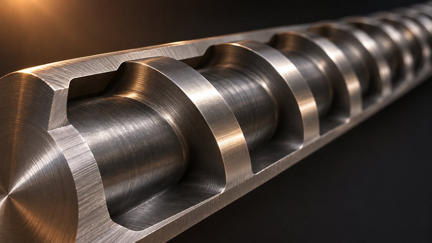
Critical Design Parameters — L/D Ratio, Compression Ratio, and Flight Geometry
Polymer-family guidelines tell you where to aim. The numbers on the screw print — L/D ratio, compression ratio, channel depth, flight width, helix angle — determine whether you actually hit the target. These are the quantitative parameters that separate a screw design for injection molding that performs reliably from one that generates a slow leak of scrap, rework, and finger-pointing between shifts. Each parameter involves a measurable trade-off, and understanding those trade-offs is what turns catalog shopping into genuine engineering.
L/D Ratio and Its Impact on Residence Time
The length-to-diameter ratio (L/D) describes how long the screw's flighted section is relative to its nominal outer diameter. Most injection molding screws fall between 18:1 and 24:1, with 20:1 still being the most common configuration shipped on general-purpose machines. A longer screw — say 24:1 versus 20:1 on the same barrel bore — gives the polymer more time under shear and more barrel surface area for conductive heating. That extra capacity improves melting efficiency, enhances mixing, and allows higher throughput before unmelts start appearing.
But there's a cost: residence time. Every additional turn of flighted length adds volume inside the barrel that must be filled with molten polymer, and that polymer sits at elevated temperature for longer before it's injected into the mold. For heat-stable resins like PP or PE in packaging applications, extended residence time is a minor concern. For thermally sensitive materials — PVC, PBT, certain TPEs, and many rubber injection molding screw design applications involving vulcanizable compounds — excessive residence time triggers degradation, discoloration, and property loss that no amount of downstream process adjustment can fix.
Here's where a critical factor enters the equation: shot-size utilization, the percentage of the barrel's melt capacity that is actually injected each cycle. Imagine a 60-ounce barrel on a 22:1 L/D machine producing a 6-ounce shot. You're using only 10% of the barrel's capacity per cycle, which means resin circulates through the heated barrel for many more cycles before it finally exits. Industry guidance commonly targets a residence time between 2 and 5 minutes for most thermoplastics, but achieving that target depends on the interplay between L/D, shot size, and cycle time — not L/D alone.
Estimating real residence time is trickier than it appears, because the simple formula (maximum shot size ÷ actual shot size × cycle time) only accounts for the melt pool ahead of the screw. It omits all the material being conveyed through the feed, transition, and metering zones. Plastics engineer Umberto Catignani has detailed a more rigorous approach using barrel factors derived from the work of Olmstead and Davis: a multiplication factor of 1.4 applies when the injection stroke is four or more screw diameters, increasing to 2.0 when the stroke is only three diameters. These factors, originally published in the Spirex "Plasticating Essentials" guide and assuming a 20:1 L/D with general-purpose compression, can increase calculated residence time by 40% or more compared to the basic equation. For a machine running a 22:1 screw, the screw inventory equation adjusts the barrel factor to account for the different L/D, yielding even more accurate estimates.
One common error compounds the problem: confusing melt density with specific gravity when converting barrel capacity from the standard GPPS rating to the actual resin being molded. Because barrel capacity is typically specified in ounces of general-purpose polystyrene (melt density ~0.97 g/cm3), a less dense melt like PP (~0.75 g/cm3) reduces the usable barrel capacity significantly — from 60 ounces of PS to roughly 46 ounces of PP. If a scheduler or quoting engineer assumes the full 60-ounce figure applies, they'll underestimate how much of the barrel each shot consumes, leading to an inaccurate barrel utilization percentage and a misleading residence-time estimate.
The practical takeaway? L/D ratio doesn't operate in isolation. You need to pair it with an honest calculation of shot-size utilization and a material-corrected barrel capacity to know whether your screw is giving the polymer enough processing time — or slowly cooking it.
Compression Ratio Selection Logic
The compression ratio is mathematically simple — feed channel depth divided by metering channel depth — but selecting the right value is anything but. As outlined in the polymer-family section above, ratios range from as low as 1.5:1 for shear-sensitive PVC to 4.0:1 for semi-crystalline nylon. The question engineers need to answer is why a specific ratio suits a specific resin, not just what number to plug in.
Three material properties drive the answer:
- Bulk density vs. melt density: A polymer with low bulk density (fluffy regrind, low-density pellets) occupies a large volume in the deep feed channel. As it melts and densifies, the channel must shrink proportionally to maintain consistent forward pressure on the melt. If the compression ratio is too low for the density change, the material doesn't compact fully and air pockets persist into the metering zone. If it's too high, the material is squeezed harder than necessary, generating excess shear heat.
- Melting behavior: Semi-crystalline resins absorb large amounts of energy at a narrow melt point, requiring more aggressive compression to supply that energy via shear. Amorphous resins soften gradually, needing less mechanical energy input. Essentra Components' technical overview reinforces this point: the higher the compression ratio, the greater the shear heat imparted to the resin and the better the heat uniformity — but also the greater the potential for creating stresses in sensitive materials.
- Melt viscosity: High-viscosity melts (like polycarbonate at processing temperature) generate more viscous dissipation for a given compression ratio than low-viscosity melts (like nylon 6 above its melt point). Two resins with identical recommended compression ratios can behave very differently in the same screw because their viscosity profiles diverge.
Published compression-ratio guidelines are starting points, not recipes. A ratio of 2.5:1 for ABS, for example, assumes a standard pellet form, a typical shot-size utilization range, and mid-range screw speeds. Change any of those assumptions — switch to regrind with lower bulk density, run the screw near maximum RPM, or drop shot utilization below 20% — and the effective compression behavior shifts. Process validation on the actual machine, mold, and resin lot is always the final arbiter.
Flight Depth, Width, and Helix Angle Trade-Offs
If compression ratio is the headline number in screw design injection molding specifications, flight depth, width, and helix angle are the fine print that determines whether that headline delivers on its promise.
Flight depth — the distance from the screw root to the top of the flight land — directly controls two opposing performance attributes. Deeper flights increase the channel's cross-sectional area, raising the volume of material the screw can move per revolution. That means higher potential throughput. But deeper channels also reduce the shear rate the melt experiences, because shear rate in a screw channel is proportional to screw speed and inversely proportional to channel depth. Lower shear means less viscous heating, less mixing intensity, and a greater risk of thermal non-uniformity in the melt. Research by Kazmer et al. demonstrated this trade-off experimentally: their general-purpose screw with relatively wide, deep channels had the highest mass throughput among five tested designs but also the poorest melt temperature consistency, producing extrudate that was visibly inhomogeneous at screw speeds above 40 RPM.
Flight width (the land width at the top of the flight) affects the balance between output capacity and pressure generation. A narrower flight land opens more channel area for material flow, boosting throughput — but it also reduces the sealing surface between the flight and the barrel wall. That wider clearance zone allows more leakage flow (melt slipping backward over the flight), which cuts into net forward output and weakens the screw's ability to build pressure. Conversely, wider flight lands seal better and generate more pressure, at the expense of reduced channel volume and increased frictional heat on the flight tip. The standard starting point is a flight width equal to approximately 10% of the screw diameter, but adjustments are common for high-pressure applications or when processing low-viscosity melts that are prone to leakage.
Helix angle — the angle of the flight relative to a plane perpendicular to the screw axis — governs how far forward material advances with each revolution. The industry standard is 17.66°, which produces a "square pitch" where the distance between adjacent flights (the lead) equals the screw diameter. This geometry balances forward conveying with sufficient channel residence for melting and mixing. Steeper helix angles push material forward faster, increasing throughput but reducing the time available for heat transfer and mixing in each zone. Shallower angles do the opposite — more residence time per turn, better mixing, but lower output. Deviations from the standard 17.66° are justified when the application demands it: the fractal screw designs studied in Kazmer's peer-reviewed research deliberately increased helix angles in downstream zones (up to 24°) to boost throughput after splitting channels into multiple parallel flights for improved melting consistency.
Screw design is always a set of engineering trade-offs — optimizing one parameter inevitably constrains another. Deeper flights raise throughput but lower shear and mixing. Higher compression ratios improve melt uniformity but risk overheating sensitive resins. Longer L/D ratios enhance plasticating capacity but extend residence time. This is precisely why application-specific engineering, grounded in the actual polymer, filler system, shot size, and cycle-time target, consistently outperforms catalog selection.
These dimensional trade-offs play out on the metal itself — and metal doesn't last forever. The same shear forces and abrasive fillers that the screw geometry must manage also attack the screw's physical surfaces. How long a well-designed screw actually maintains its geometry depends entirely on what it's made of and how it's protected, which brings the discussion squarely to metallurgy, coatings, and wear resistance.
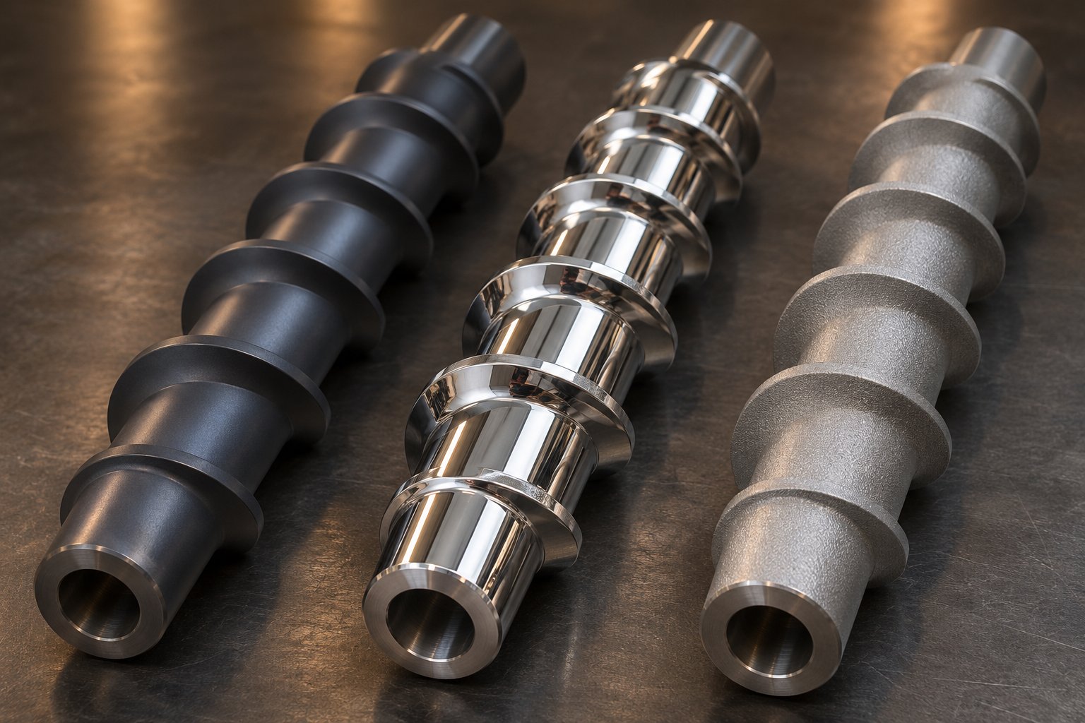
Injection Molding Screw Material Selection, Surface Treatments, and Wear Resistance
A perfectly optimized flight geometry means nothing if the metal underneath it erodes in six months. Every compression ratio, every channel depth, every carefully specified barrier clearance is only as durable as the screw's base material and surface protection allow it to be. Wear doesn't just shorten the screw's life — it silently alters the geometry you worked so hard to get right, drifting compression ratios, opening flight clearances, and degrading melt quality in ways that mimic dozens of other process problems. That's why injection molding screw material selection and surface treatment are inseparable from screw geometry in any serious specification effort.
Base Materials — Nitralloy, Tool Steel, and Stainless Alloys
The base metal of an injection molding screw has to balance three competing demands: hardness to resist abrasion, toughness to absorb impact and cyclic stress without cracking, and corrosion resistance to survive chemical attack from aggressive polymers and their decomposition products. No single alloy optimizes all three simultaneously, so the choice always starts with the resin and filler system the screw will process.
4140 nitrided steel is the workhorse for standard applications. It's a medium-carbon, chromium-molybdenum alloy that responds well to nitriding — a surface-hardening process that diffuses nitrogen into the steel to create a hard case while leaving the core tough and ductile. For unfilled commodity resins like PP, PE, ABS, and general-grade polycarbonate, a nitrided screw for injection molding provides a practical balance of wear resistance and cost. You'll find this material on the majority of general-purpose screws shipped with new machines. Its limitation shows up quickly, however, when abrasive fillers enter the picture. Glass fiber, mineral fillers, and even high concentrations of titanium dioxide pigment wear through the nitrided case faster than most operators expect.
D-2 and CPM (Crucible Particle Metallurgy) tool steels step in when abrasion is the dominant wear mechanism. D-2 is a high-carbon, high-chromium die steel with excellent wear resistance, commonly used for screws processing glass-fiber-reinforced nylon, mineral-filled polypropylene, and other compounds that chew through 4140 in a fraction of the expected service life. CPM steels — produced through a powder metallurgy process that yields an extremely uniform carbide distribution — take abrasion resistance a step further. As Stephen Surley of SpiraMelt Technologies has detailed, these upgraded materials can extend screw life by two to four times compared to standard nitrided steel in high-abrasion applications. The trade-off is cost: tool-steel screws typically run 50-80% more than their 4140 equivalents.
Stainless alloys become essential when the threat is chemical rather than mechanical. PVC processing liberates hydrochloric acid at elevated temperatures, and fluoropolymers release hydrofluoric acid — both of which corrode standard steels aggressively. Stainless grades like 440C or 17-4 PH offer the corrosion resistance these applications demand, though they sacrifice some wear resistance compared to tool steels. For PVC operations, the choice is straightforward: a corroded screw fails far sooner than one that wears gradually, and the HCl released during degradation can accelerate wear on every surrounding component in the plasticizing unit.
The key insight is that injection molding screw design doesn't end at geometry — the metallurgy must be matched to the specific resin and filler system with the same rigor applied to flight depths and compression ratios.
Surface Treatments and Coatings for Wear Resistance
Base metal selection sets the foundation, but surface treatments and coatings multiply its effective life by hardening or shielding the screw's contact surfaces. Choosing the right injection molding screw surface treatment requires identifying which wear mechanism dominates your application, because each mechanism attacks the screw differently and demands a different protective strategy.
Three wear modes operate in plasticizing units, often simultaneously:
- Adhesive wear (resin-on-metal): Polymer bonds to the screw surface under heat and pressure, then tears away, pulling microscopic metal particles with it. This is common with sticky resins like nylon and PVC. It manifests as surface pitting and galling on the screw root and flight flanks.
- Abrasive wear (filler-on-metal): Hard particles in the compound — glass fiber, calcium carbonate, talc, titanium dioxide — physically grind the screw surfaces. Empirical data from thousands of screw rebuilds confirms that abrasive wear concentrates in high-pressure zones, particularly the transition section and the last few turns of metering, where elevated pressure and temperature increase frictional contact. Particle shape matters significantly: sharp, angular fillers cause more severe wear than round, smooth ones.
- Corrosive wear (chemical attack): Degradation byproducts — HCl from PVC, acidic decomposition products from certain flame retardants — chemically etch the screw surface, roughening it and accelerating adhesive and abrasive mechanisms. This combined effect, sometimes called corrosion-erosion, can be far more destructive than any single mechanism acting alone.
With the dominant wear mode identified, you can match the right surface protection:
Nitriding (gas and ion/plasma) is the most common and cost-effective treatment. Gas nitriding diffuses nitrogen into the steel surface at temperatures around 500°C, creating a hard compound layer (typically 65-70 HRC on the surface) that resists abrasion. Ion (plasma) nitriding achieves similar or superior hardness with better process control and less distortion, making it preferable for tighter-tolerance screw geometries. Nitriding typically extends service life by 1.5 to 2 times in moderately abrasive applications. Its limitation? The hardened case is relatively thin — once worn through, the softer core underneath erodes rapidly.
Chrome plating provides a smooth, low-friction surface that reduces adhesive wear and improves resin release. It's commonly applied to screws processing sticky polymers where material hang-up and degradation are primary concerns. Chrome doesn't offer the same abrasion resistance as carbide coatings, but its excellent release properties and moderate corrosion resistance make it a practical choice for PVC and certain engineering resins.
Tungsten carbide thermal spray delivers the highest abrasion resistance available for the most demanding filled-compound applications. The coating, applied through HVOF (high-velocity oxy-fuel) or plasma spray processes, creates an extremely hard surface layer that resists even aggressive glass-fiber abrasion. This treatment is justified when standard nitrided or chrome-plated screws require replacement every few months — the higher upfront cost pays back through dramatically extended service intervals.
Bimetallic barrel liners complement screw surface treatments by hardening the barrel bore against the same wear mechanisms. A screw coated in tungsten carbide running inside a soft, worn barrel still loses performance, because the growing radial clearance between flight OD and barrel ID allows increased leakage flow. Pairing the right screw treatment with a matched barrel liner is the only way to preserve the geometry that the injection molding screw design was engineered to deliver.
Recognizing Wear Patterns and Planning Replacement
Here's where screw wear becomes genuinely insidious: it's a slow, gradual process that mimics other process problems. As Surley's rebuild experience confirms, minor wear has little immediate effect on performance because operators compensate — increasing backpressure, raising screw speed, adjusting barrel temperatures — without realizing they're masking progressive geometry loss. By the time scrap rates spike or energy consumption soars, the screw may be so far gone that rebuilding is marginal and replacement is the only reliable option.
A common rule of thumb considers a screw ready for replacement when flight-OD clearance reaches four times the original tolerance. But this guideline oversimplifies the picture. Resin viscosity matters: a high-viscosity melt like polycarbonate tolerates more radial clearance before leakage flow becomes significant, while a low-viscosity resin like polypropylene hemorrhages output with the same wear. Surley's rate-loss calculations for PP versus PE under identical wear conditions showed measurably higher throughput loss for the lower-viscosity PP — a distinction that rules of thumb ignore entirely.
The only reliable approach is periodic measurement — pulling the screw at scheduled intervals and recording flight OD, channel depth, and root diameter at multiple points along the length. Tracking these dimensions over time reveals wear-rate trends that enable predictive replacement scheduling instead of reactive emergency shutdowns.
The symptoms below are signals that your screw's geometry has drifted far enough to warrant immediate inspection. Each points to a specific wear condition:
- Increasing recovery time with no process changes: Flight-land wear has increased radial clearance, reducing the screw's pumping efficiency and requiring more revolutions to build the same shot volume.
- Shot-weight variation beyond historical range: Worn flight ODs allow inconsistent leakage flow, and the non-return valve's sealing surfaces may also be eroded, compounding the inconsistency.
- Rising melt temperature at the same RPM and backpressure: Increased clearance forces the melt to recirculate over worn flights, subjecting it to additional shear passes and driving up temperature — a phenomenon that Surley identifies as one of the earliest measurable indicators of significant OD wear.
- Higher energy consumption to maintain throughput: The screw runs faster to compensate for lost pumping efficiency, drawing more motor power for the same output rate.
- Black specks or degraded material in parts: Root wear creates pockets and rough surfaces where polymer hangs up and degrades over time. This is especially problematic with PVC, where localized stagnation triggers HCl release and accelerating corrosive attack.
- Loss of color dispersion or filler distribution quality: Worn mixing sections and barrier flights lose the tight clearances that their designs rely on for effective dispersive or distributive action.
- Surging or cyclical output variation: Severe root wear or compression-ratio drift destabilizes the solid-bed conveying and melting dynamics, producing rhythmic output fluctuations that no amount of backpressure adjustment can fully correct.
Every one of these symptoms can also be caused by something other than screw wear — a failing heater band, a degraded non-return valve, a resin-lot variation. That ambiguity is precisely why periodic dimensional measurement is irreplaceable. Without hard data on flight-land dimensions, troubleshooting becomes guesswork, and the screw — the single most influential component in the plasticizing unit — quietly escapes scrutiny while operators chase phantom causes elsewhere.
Of course, the screw itself is only one half of the sealing equation. The component that sits at the very front of the screw — the non-return valve — wears at least as fast and has an equally direct impact on shot-to-shot consistency. Its design, condition, and maintenance deserve their own examination.
Check Rings, Screw Tips, and Non-Return Valve Selection
A screw with perfect flight geometry and premium metallurgy still can't guarantee consistent parts if the component at its very tip leaks. The non-return valve — that small assembly sitting between the screw's metering zone and the mold — is the gatekeeper of shot-to-shot repeatability. It decides whether the precise volume of melt the screw prepared actually reaches the cavity, or whether some of it slips backward during injection, robbing the part of material and the process of stability. Yet in many facilities, injection molding check ring selection receives less engineering attention than the screw itself, and the valve is only inspected after quality problems have already escalated.
Understanding how this component works, which design variants exist, and how the screw tip profile interacts with melt flow is essential for anyone serious about controlling cushion consistency and part-weight repeatability.
How the Non-Return Valve Works During Injection
The most common injection molding non-return valve design is the sliding check ring, sometimes called a free-flow check ring. Picture three core components threaded onto the front of the screw: a retainer (the screw tip body), a check ring that slides freely along the retainer's shaft, and a rear seat that forms the sealing surface.
During screw recovery, the screw rotates and moves backward, pumping melt forward past the check ring. The melt pressure pushes the ring forward against the retainer, opening a flow channel between the ring's rear face and the seat. Molten polymer streams through this gap and accumulates ahead of the screw, building the shot.
The moment injection begins, the screw drives forward like a plunger. Melt pressure in front of the screw now exceeds the pressure behind it, slamming the check ring rearward against the seat. When it seats properly, the ring-to-seat contact creates a seal that prevents backflow — and the full volume of accumulated melt travels forward through the nozzle and into the mold.
Sounds straightforward? In theory, it is. In practice, three geometric details determine whether that seal is reliable cycle after cycle:
- Ring-to-seat clearance: The radial fit between the check ring's outer diameter and the barrel bore, plus the flatness and finish of the ring's rear face against the seat, govern how completely the valve closes. As Turner Group's process-repeatability analysis emphasizes, even the machine's exceptional positional precision becomes irrelevant if the check ring can't seal consistently — the screw may repeat the same stroke, but the actual volume of material delivered to the mold changes from shot to shot.
- Ring length and travel distance: A longer check ring takes more time to travel from the open (forward) to closed (rearward) position. During that transition window, melt leaks backward. If the ring is too long or if front-seat wear creates excessive travel, the valve doesn't seat within the injection phase, and cushion becomes erratic.
- Flow-path geometry: The annular gap through which melt passes during recovery must be large enough to avoid restricting flow and creating excessive pressure drop, but not so oversized that the ring becomes sluggish in seating. This balance is why experienced screw-tip manufacturers perform flow analysis calculations for every custom tip rather than treating any design as inherently "free flow."
Wear on any of these surfaces — the ring OD against the barrel wall, the rear seat face, or the front seat on the retainer — degrades sealing performance gradually. Check ring deterioration develops slowly through normal production and accelerates with abrasive fillers, corrosive resins, or demanding processing conditions. Because the degradation is incremental, operators often compensate by adjusting pressures, positions, or hold times — temporarily masking a mechanical issue rather than correcting it.
Ball-Check and Poppet Alternatives
The sliding check ring dominates the industry, but it isn't the only non-return valve for injection molding screw applications. Two alternatives — ball-check and poppet-style valves — address specific process challenges where the standard ring design falls short.
Ball-check valves use a free-floating ball (or similar sphere) inside a housing that plugs a flow hole during injection. Their simplified internal geometry makes them a practical choice for shear-sensitive materials like polycarbonate and acrylic, where the tortuous flow paths in some check-ring assemblies can create localized degradation. Ball checks also offer a more positive shutoff with low-viscosity materials or very small shot sizes, where a sliding ring may not generate enough differential pressure to seat quickly. As technical documentation from Molders Services notes, quick-shutoff poppet-style variants were designed specifically for applications demanding exceptionally high sealing performance with thin, fast-flowing melts.
Poppet valves operate on a similar principle — a tapered plug seats into a matching orifice during injection — and share the ball check's advantage of rapid, positive shutoff. They're especially useful in micro-molding or medical applications where shot volumes are tiny and even minor leakage represents a significant percentage of the total shot.
Both alternatives come with a notable trade-off, however. Because the sealing OD of ball-check and poppet designs rotates with the screw, the outer surface continuously contacts the barrel bore under rotation. This introduces the likelihood of premature barrel internal-diameter wear — a concern that doesn't apply to the standard sliding check ring, whose outer ring spins independently and contacts the barrel only under static sealing pressure during injection. For most commodity and engineering resins processed at standard volumes, the sliding check ring remains the most versatile and durable starting point.
Injection Molding Screw Tip Geometry and Its Influence on Melt Flow
The screw tip — the retainer body that threads onto the front of the screw and holds the check ring assembly together — is often treated as a structural fastener. In reality, its geometry directly affects melt quality, color-change time, and the risk of material degradation.
Two aspects of injection molding screw tip geometry matter most:
Taper angle and nose profile. A blunt or stepped tip creates dead spots — recesses and sharp transitions where polymer stagnates, overheats, and eventually degrades into black specks or discolored streaks. This matters for every resin but becomes critical for thermally sensitive materials like POM (which releases formaldehyde), PVC, and optical-grade PMMA where any discoloration is a reject. Streamlined tip profiles — smooth, gradual tapers with no abrupt diameter changes — minimize the residence-time distribution spread, meaning nearly all of the melt moves through the tip at a similar velocity rather than some fraction hanging up indefinitely. Precision internal geometries that eliminate sharp edges, steps, and dead ends are what distinguish a well-engineered tip from a commodity replacement part.
Color-change efficiency. Every dead spot in the tip assembly is a reservoir of the previous color that bleeds slowly into subsequent shots. A tip with poor internal geometry can add dozens — sometimes hundreds — of purge cycles to a color change, wasting resin, machine time, and operator patience. Streamlined designs flush cleanly because they don't give the old material anywhere to hide.
The choice between a 3-piece and 4-piece sliding check ring design also influences durability. In a 4-piece configuration, the front seat is manufactured as a separate component from the retainer, allowing the use of a harder, more durable material for the seat while keeping the retainer at a lower hardness — which means a broken stud can actually be drilled out if it seizes, an option that's nearly impossible with an integrated 3-piece design. For operations running abrasive or corrosive resins, this modularity translates directly into lower long-term replacement costs and faster maintenance turnarounds.
The non-return valve is the most frequently replaced wear component on the plasticizing unit. Its condition should be audited — through cushion-consistency monitoring and shot-weight measurement — whenever part-weight variation exceeds acceptable tolerances, before chasing process parameters that may only mask an underlying mechanical problem.
Monitoring cushion stability and shot-to-shot weight is the simplest, most informative diagnostic available. If the cushion drifts or part weights scatter beyond historical norms and no process variable has changed, the check ring assembly deserves immediate inspection — not another round of pressure and temperature adjustments. As Turner Group's analysis concludes, the fundamental question isn't whether the machine can make a good part — it's whether it can deliver the same amount of material, the same way, cycle after cycle.
With screw geometry, metallurgy, and the non-return valve all accounted for, the remaining challenge is integrating these individual decisions into a coherent specification — a structured workflow that moves from application requirements to a complete, manufacturable screw design.
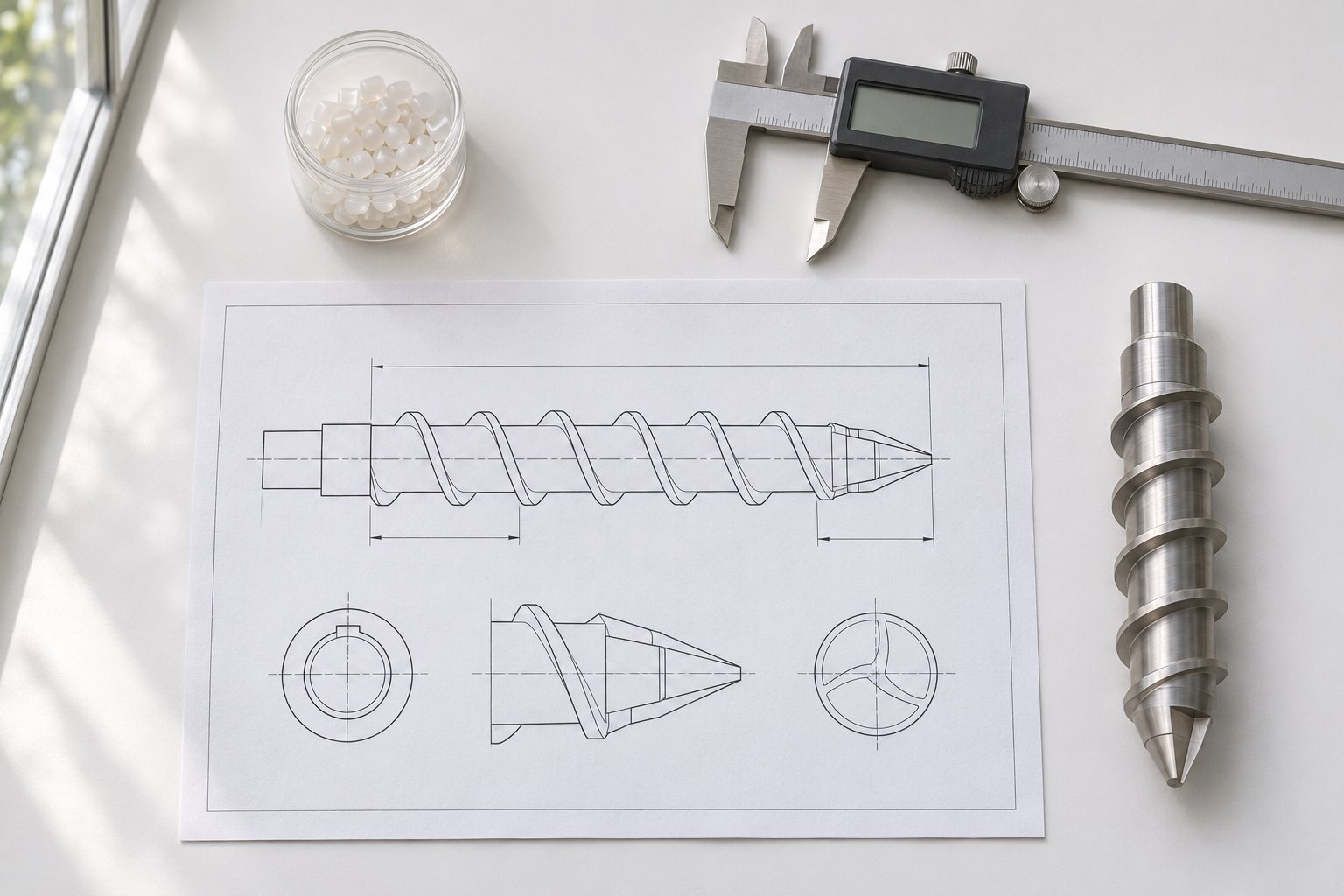
How to Specify an Injection Molding Screw: A Decision Framework
Geometry, metallurgy, non-return valve — each piece has been examined individually. The real engineering challenge is assembling them into a single, coherent specification that accounts for the polymer, the machine, and the production target simultaneously. Most facilities skip this step entirely, defaulting to whatever screw shipped with the machine or copying a competitor's setup without validating whether the same logic applies to their own application. The result is a custom injection molding screw specification that isn't custom at all — it's an inherited guess.
What follows is a structured injection molding screw selection guide you can use as a repeatable workflow, whether you're specifying a screw for a new application or auditing an existing one that isn't performing.
Step-by-Step Screw Specification Workflow
Think of this sequence as a decision chain — each step narrows the design space so the next step has fewer variables to resolve. Skipping a step, or tackling them out of order, almost always leads to rework downstream.
- Identify the primary resin and any fillers or additives. The polymer family dictates compression ratio range, shear tolerance, and corrosion risk. Fillers determine abrasion severity and mixing requirements. Start here because every subsequent decision references this input.
- Determine the machine barrel diameter and available L/D. You can't specify a 24:1 screw for a machine that only accepts 20:1. Record the barrel bore ID, maximum flighted length, and drive interface (spline or keyed shank) before moving forward.
- Calculate shot-size utilization and residence time. Divide your actual shot weight (corrected for melt density, not specific gravity) by the barrel's melt capacity. Apply the appropriate barrel factor for your L/D and injection stroke to estimate real residence time. If the number exceeds your polymer's thermal stability window, consider a smaller barrel or shorter L/D — not a process band-aid.
- Select the appropriate screw architecture. Use the polymer and application requirements from Steps 1-3 to choose between general-purpose, barrier, mixing-enhanced, or vented two-stage configurations. Refer to the architecture comparison table in Section 3 as your starting filter.
- Specify compression ratio and flight depths based on polymer family. Pull recommended ranges from the polymer-to-geometry reference table in Section 4, then adjust for your specific pellet form (virgin vs. regrind), bulk density, and any unusually high or low shot-size utilization.
- Choose base metallurgy and surface treatment based on the dominant wear mode. Abrasive fillers push toward tool steel and tungsten carbide coatings. Corrosive resins demand stainless alloys or chrome plating. Unfilled commodity resins are well served by nitrided 4140. Match the protection to the threat.
- Specify the non-return valve type. Sliding check ring for most applications, ball-check or poppet for shear-sensitive or micro-molding work. Define the tip profile — streamlined for thermally sensitive resins, modular 4-piece for abrasive or corrosive environments where seat replacement matters.
This sequence won't hand you a finished screw print — but it will produce a specification package detailed enough to evaluate proposals from any manufacturer and catch mismatches before metal gets cut.
When Simulation Supports the Design Process
For high-stakes applications — expensive resins, tight tolerances, novel polymer blends — simulation software can validate your specification choices before you commit to physical hardware. Tools like Compuplast, which specializes in polymer processing simulation for screw and die design, allow engineers to model channel flow, shear-rate distribution, temperature profiles, and pressure generation across the full screw length. General-purpose CFD platforms offer similar capabilities for teams with in-house computational expertise.
Simulation doesn't replace process validation on the actual machine. What it does is compress the trial-and-error cycle by eliminating geometries that clearly won't work — a metering depth that produces excessive shear heating, a transition taper that leaves unmelts at your target RPM, a vent zone that floods under the expected throughput range. When a single application-specific screw design injection molding project can cost thousands of dollars in material and machine time, eliminating even one physical iteration pays for the modeling effort.
Working with a Screw Design Engineering Partner
Here's a reality most engineers eventually confront: how to specify an injection molding screw rigorously requires integrating polymer science, machine constraints, and production economics into a single design — and very few molding operations have that full skill set in-house. Process engineers understand the resin. Maintenance teams know the machine. Production managers own the cycle-time and quality targets. But translating all of those inputs into a manufacturable screw specification with the right flight depths, compression profile, mixing geometry, metallurgy, and surface treatment is a specialized discipline.
This is where partnering with a dedicated screw engineering service accelerates the process. For example, NANHAIYA's custom screw design service is structured around exactly this kind of application-specific input — their engineers review flight depths, compression ratios, mixing sections, materials, and surface treatments relative to the polymer behavior, machine dimensions, temperature limits, and production targets before moving to manufacturing. It's one credible option among several in the market, but it illustrates the broader point: specialists who do this work daily can spot design conflicts and optimization opportunities that generalist teams would need multiple physical iterations to discover.
Whether you work with an external partner or build the expertise internally, the goal is the same — a specification package grounded in the seven-step logic above, validated against your actual process conditions, and documented well enough that the next screw order doesn't start from scratch. That documentation, paired with the measurable process outcomes it enables, is what transforms screw selection from a procurement task into an engineering investment with a trackable return.
From Screw Geometry to Process Economics and Next Steps
An engineering investment with a trackable return — that phrase deserves unpacking, because it cuts to the heart of how most facilities misunderstand screw purchases. A new screw shows up on a capital equipment line item or a maintenance PO. It gets treated as a replacement part, not a process variable. The old screw wore out, so you buy another one — same geometry, same metallurgy, same vendor. The cost is visible. The return? Nobody measures it, because nobody connects screw geometry to the four process outcomes it directly controls: cycle time, scrap rate, energy consumption, and maintenance intervals.
That disconnect is expensive. And it's the reason injection molding screw design optimization deserves a total-cost-of-ownership lens rather than a line-item purchase mentality.
Connecting Screw Geometry to Measurable Process Outcomes
Every geometric decision covered in the preceding sections — compression ratio, L/D, flight depth, mixing elements, metallurgy, non-return valve type — cascades into production-floor metrics that hit the P&L statement. Here's how those connections work in practice:
Cycle time. Faster plasticizing means shorter recovery, which means the screw finishes preparing the next shot before the mold opens. A barrier screw with properly matched compression and mixing geometry can shave seconds off recovery compared to a general-purpose design running the same resin at the same RPM. Over hundreds of thousands of cycles per year, those seconds compound into hours of additional productive capacity — without buying another machine.
Scrap rate. Improved melt homogeneity eliminates the temperature gradients and viscosity swings that cause short shots on one cycle and flash on the next. Better mixing distributes color and additives uniformly, removing the visual defects that send parts to the reject bin. Shot-weight consistency — driven by both screw geometry and a properly sealing non-return valve — keeps dimensional tolerances tight enough to avoid sorting, rework, or customer complaints.
Energy consumption. A screw geometry matched to the polymer melts resin efficiently at lower backpressure settings, reducing the mechanical energy the drive motor must supply per kilogram of throughput. Oversized screws running at low utilization waste energy heating polymer that circulates through the barrel far longer than necessary. Right-sizing the geometry and matching L/D to actual shot requirements trims the energy budget quietly but measurably across every shift.
Maintenance intervals. Appropriate metallurgy and surface treatment — nitrided steel for commodity resins, tool steel or tungsten carbide for glass-filled compounds, stainless for corrosive PVC — means the screw holds its geometry longer. Compression ratios don't drift. Flight clearances stay within tolerance. The non-return valve seats cleanly. When maintenance intervals extend, unplanned downtime shrinks, and the troubleshooting cycles that consume engineering hours diminish in frequency.
None of these outcomes exist in isolation. A screw that plasticizes faster also tends to run at lower melt temperatures, which reduces thermal degradation, which cuts scrap, which lowers material cost per part. The ASQ cost-of-quality framework organizes this cascade neatly: screw geometry process optimization injection molding falls squarely into the prevention cost category — money spent upfront to avoid quality problems before they occur. Prevention investments reduce the far more expensive appraisal costs (inspection, sorting, testing) and failure costs (scrap, rework, warranty claims, customer returns) downstream. Quality-management research consistently shows that companies lose 10-15% of operating costs to poor quality. Shifting even a fraction of that loss into prevention through better screw engineering changes the math dramatically.
The challenge, of course, is that prevention costs are visible on the purchase order while the savings they generate are distributed across dozens of production metrics over months and years. That's why documenting the specification logic — and the process data that follows — matters as much as the screw itself.
Building Your Screw Design Specification Package
Whether you're working with an internal engineering team or an external design partner, the quality of the screw you receive depends entirely on the quality of the inputs you provide. Imagine handing a screw manufacturer nothing but a barrel diameter and a resin name — the result will be a generic geometry that might run but won't optimize. A complete specification package eliminates ambiguity and gives the designer the constraints needed to make informed trade-offs.
Here's the checklist of deliverables you should compile before requesting any screw design quote or initiating an internal design review:
- Resin data sheet: Full material grade, supplier, and technical data sheet including melt flow index, melt density, recommended melt temperature range, thermal degradation temperature, and moisture sensitivity classification.
- Filler and additive details: Type, loading percentage, particle morphology (fiber vs. particulate, sharp vs. round), and any known wear or corrosion history with current equipment.
- Machine specifications: Barrel inside diameter, maximum flighted screw length (and corresponding L/D), maximum screw RPM, available drive torque, shank interface (spline type and dimensions), and feed-throat configuration (smooth-bore vs. grooved).
- Shot weight and barrel utilization: Actual part weight plus runner weight per cycle, calculated as a percentage of the barrel's melt capacity corrected for the specific resin's melt density — not general-purpose polystyrene equivalent.
- Target cycle time: Total cycle and, if known, the recovery-time budget within that cycle.
- Quality tolerances: Part-weight repeatability targets (e.g., Cpk requirements), allowable melt-temperature variation shot to shot, visual standards for color consistency or surface quality, and any dimensional tolerances driven by the mold and application.
- Current screw details (if replacing): Existing screw geometry (zone lengths, flight depths, compression ratio), metallurgy, service life to date, and any known performance shortcomings or wear patterns.
- Production environment: Number of shifts, annual cycle count, frequency of resin or color changes, and any planned material transitions that the new screw should accommodate.
This package looks like a lot of paperwork — until you compare it to the cost of iterating through two or three poorly specified screws before landing on one that actually works. Every item on the list eliminates a variable that would otherwise become a trial-and-error experiment on the production floor.
Injection molding screw performance improvement doesn't come from buying a more expensive screw. It comes from buying the right screw — one engineered against documented constraints, validated through process data, and maintained on a schedule informed by measured wear rates rather than arbitrary calendar intervals. The injection molding screw cost of ownership drops not when you find a cheaper supplier, but when the geometry, metallurgy, and valve design align so precisely with your application that cycle times shorten, scrap disappears from the quality log, and the maintenance team stops pulling the screw every few months to chase problems that were built into the specification from day one.
If building that specification internally feels like a stretch given your current team's bandwidth or expertise, working with a dedicated engineering service is a practical shortcut. NANHAIYA's custom screw design service, for example, is structured around exactly the inputs listed above — polymer behavior, machine dimensions, temperature limits, and production targets — to help injection molding teams evaluate screw geometry before committing to custom manufacturing. It's not the only path, but it's a well-organized one for operations that want to move from catalog defaults to application-specific engineering without building that capability from scratch.
Frequently Asked Questions About Injection Molding Screw Design
1. What is injection molding screw design and why does it matter?
Injection molding screw design is the engineering discipline of specifying a screw's L/D ratio, compression ratio, flight depth, helix angle, and zone proportions to convert solid pellets into a uniform, thermally homogeneous melt. It matters because the screw simultaneously performs solid conveying, melting, melt conveying, mixing, and pressure generation. When screw geometry is mismatched to the polymer or process window, facilities experience inconsistent shot weights, poor melt homogeneity, elevated scrap rates, and longer cycle times. Proper screw specification — tailored to the resin family, filler system, and machine constraints — is one of the highest-leverage investments a molding operation can make to improve part quality and reduce total production cost.
2. How do I choose the right compression ratio for my injection molding screw?
Compression ratio — feed channel depth divided by metering channel depth — should be selected based on three key material properties: the difference between bulk density and melt density, the polymer's melting behavior (sharp melt point vs. gradual softening), and melt viscosity at processing temperature. Semi-crystalline resins like nylon require higher ratios (3.0:1 to 4.0:1) because their crystalline structure absorbs significant energy during melting. Amorphous resins such as ABS and polycarbonate perform well at lower ratios (2.0:1 to 2.5:1). Shear-sensitive materials like PVC need the lowest ratios (1.5:1 to 2.0:1) to prevent thermal degradation. Published ranges are starting points — process validation on your actual machine, mold, and resin lot is always the final step.
3. What is the difference between a general-purpose screw and a barrier screw?
A general-purpose (GP) screw uses a single continuous flight with a standard zone-length split (typically 50-25-25 or 50-30-20 for feed-transition-metering). It handles a broad range of commodity resins acceptably but suffers from solid-bed breakup in the transition zone, leading to melt-temperature inconsistency and unmelts. A barrier screw introduces a secondary flight in the transition zone that physically separates the solid bed from the melt pool, preventing solid-bed fracture and delivering tighter melt-temperature distribution. Barrier designs are popular upgrades for PE, PP, and nylon processing. However, they are more sensitive to flight-land wear and can develop stagnation zones that produce degradation and black specks if not maintained with appropriate inspection intervals.
4. How does screw wear affect injection molding part quality?
Screw wear progressively alters the engineered geometry — opening flight-to-barrel clearances, reducing compression ratios, and degrading mixing-section performance. The symptoms mimic other process problems, making diagnosis difficult without periodic dimensional measurement. Common indicators include increasing recovery time, shot-weight variation beyond historical norms, rising melt temperature at unchanged settings, higher energy consumption, black specks from material hang-up on roughened surfaces, and loss of color or filler distribution quality. Because wear develops gradually, operators often compensate by adjusting backpressure, RPM, or temperatures — temporarily masking a mechanical issue. Scheduled screw pulls with dimensional tracking at multiple points along the screw length enable predictive replacement rather than reactive emergency shutdowns.
5. What should I include in a screw design specification package?
A thorough specification package should contain: the full resin data sheet (including melt density, recommended temperature range, and thermal degradation limit), filler and additive details (type, loading percentage, particle shape), machine specifications (barrel bore ID, available L/D, maximum RPM, drive torque, shank interface, and feed-throat type), actual shot weight as a percentage of melt-density-corrected barrel capacity, target cycle time, quality tolerances (Cpk, melt-temperature variation, visual standards), current screw details if replacing (zone lengths, flight depths, compression ratio, metallurgy, service history), and production environment data such as shift count and color-change frequency. Providing these inputs to a specialized engineering partner like NANHAIYA's custom screw design service ensures trade-offs are resolved before metal is cut, reducing costly physical iterations.
Written by
Nanhaiya Technical Team
Zhoushan Nanhaiya Plastic Machinery Co., Ltd.
The Nanhaiya technical team supports screw and barrel manufacturing projects through application review, technical communication, custom manufacturing coordination, and production and quality control.
Discuss Your Application
Related Articles
More insights on screw barrel technology and plastics processing.
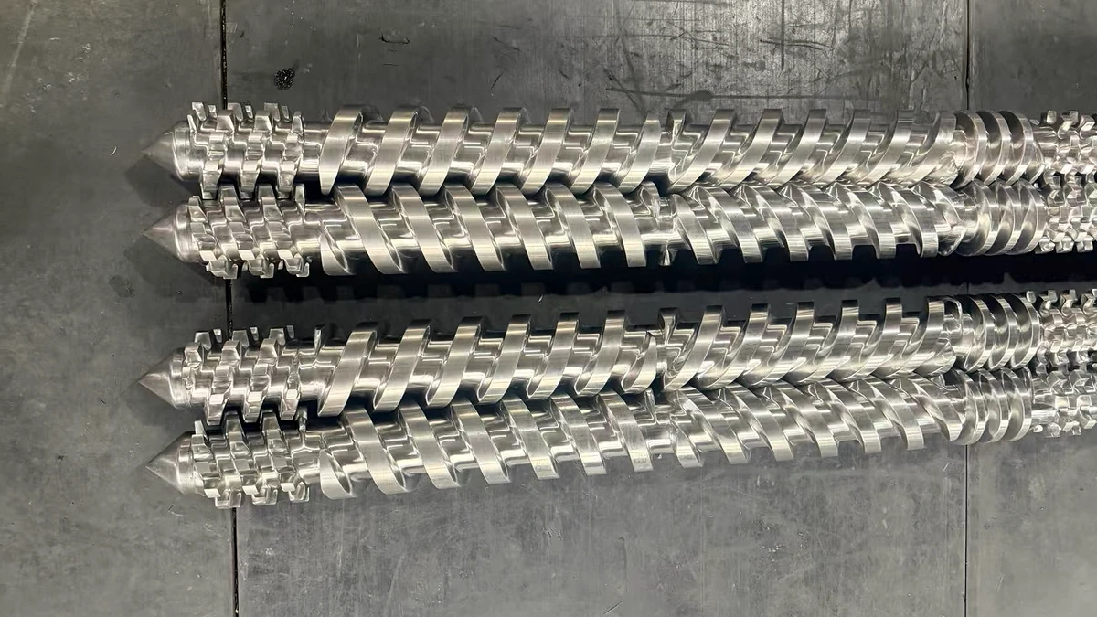
Extruder Screw Types Decoded: Match the Right Design to Your Resin
Nov 18, 2026
Learn how extruder screw types - barrier, wave, vented, twin-screw, and more - solve specific processing problems. Match the right design to your resin and application.
Read Article
Carbon Black Dispersion Fundamentals Every Formulator Gets Wrong
Nov 10, 2026
Learn why carbon black dispersion fails and how to fix it. Grade selection, dispersant chemistry, equipment, QC testing, and stability — all in one guide.
Read Article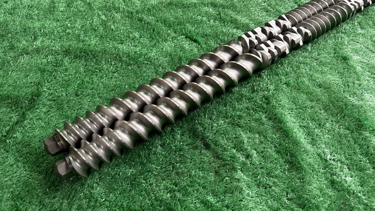
Extrusion Mixing: Why Your Screw Configuration Still Falls Short
Nov 9, 2026
Learn how extrusion mixing works, from distributive vs dispersive mechanisms to kneading block geometry, screw configuration, and SME-based quality monitoring.
Read ArticleLooking for something else?
Search by material, symptom or product and jump straight to the relevant page.
These are navigation suggestions based on keyword matching — not a quotation, not a delivery commitment, and not a substitute for engineering review. Final specification is confirmed by our engineers against your drawings and processed material.
Need help with screw barrel selection?
Share your machine model, processed material and application. Our team can help with pricing and technical support.