

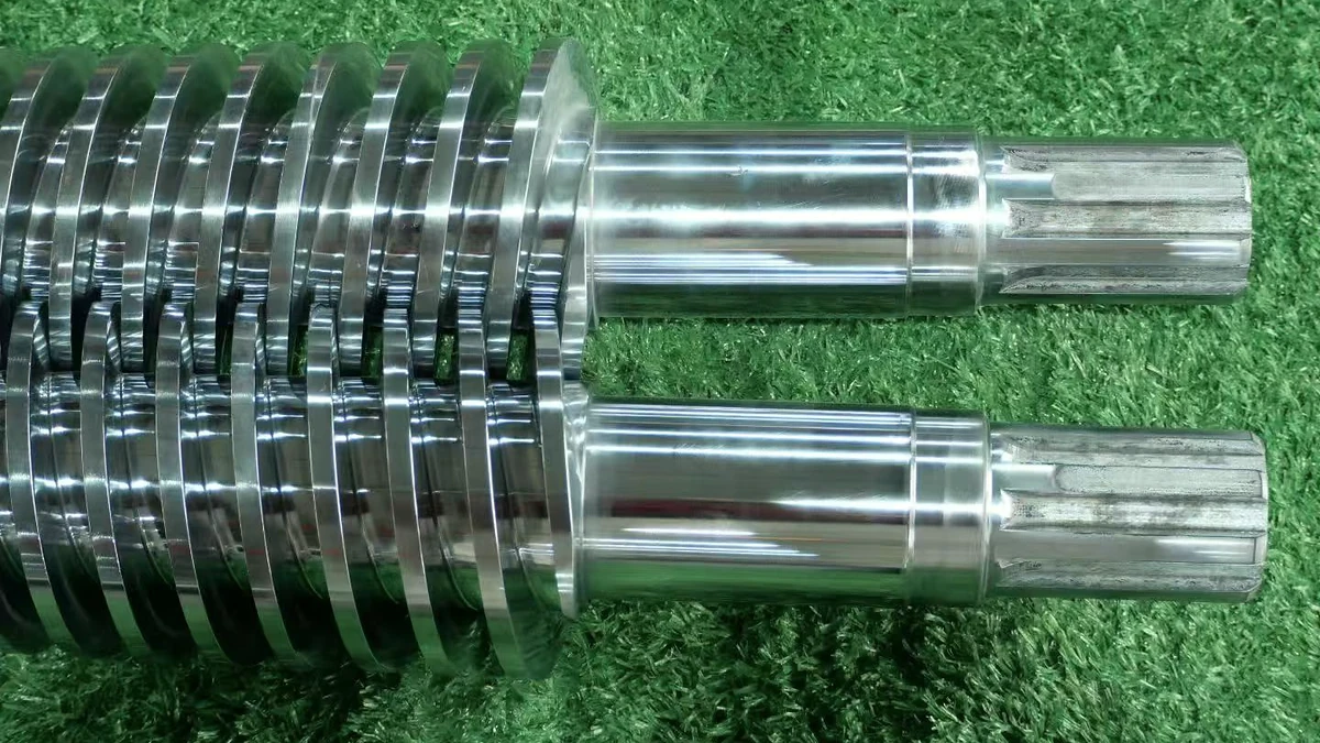
What Extruder Torque Is and Why It Matters
Every polymer extrusion line has a ceiling — and more often than not, that ceiling is set by torque. Yet torque remains one of the most misunderstood parameters on the production floor, overshadowed by barrel temperatures, screw speed, and die pressure in daily conversations. This article breaks down extruder torque from first principles through advanced troubleshooting, giving both newcomers and veteran engineers a single, manufacturer-neutral technical reference they can rely on.
Defining Extruder Torque in Practical Terms
Extruder torque is the rotational force transmitted through the drivetrain — from the electric motor, through the gearbox, and into the screw — that overcomes the resistance of the polymer melt and any fillers during processing. Measured in Newton-meters (Nm), it represents the twisting effort the screw must exert to convey, compress, melt, mix, and push material through the die. Think of it like turning a wrench against a stubborn bolt: the harder the bolt resists, the more torque your hand must apply. Inside an extruder, the "bolt" is viscous polymer fighting every flight surface along the barrel.
Two perspectives make this concept actionable. The first is mechanical capability — the maximum rotational force the motor-gearbox-screw chain can deliver, governed by component ratings and gear ratios. Equipment like the DLE series-high torque single screw extruder reducer, for example, is purpose-built to maximize this capability for demanding single-screw applications. The second perspective is process demand — the rotational force the material actually requires under a given set of conditions. When demand exceeds capability, you get torque overload alarms, gearbox wear, or worse. When capability far exceeds demand, you've overspent on drivetrain hardware you'll never use. Every decision in extruder torque calculation — from motor sizing to screw geometry — sits at the intersection of these two lenses.
Why Torque Is the Hidden Bottleneck in Extrusion
Imagine pushing throughput higher on a compounding line. You increase the feed rate, expecting the motor's kilowatt rating to be the constraint. Instead, the torque percentage on your HMI climbs past 85% and trips a safety fault — long before the motor runs out of power. This scenario plays out routinely because peak torque during startup with cold material can exceed steady-state running torque by 20-40%, eating into headroom that looked generous on paper. The gearbox, not the motor, often sets the true production ceiling.
Extruder torque is not just about power — it reflects the live interaction between machine design, polymer rheology, and process conditions. Misunderstand any one of these, and the drivetrain pays the price.
Many operators underestimate this role because torque limits are invisible until they're exceeded. Thermal limits announce themselves through degraded product. Volumetric limits show up as incomplete screw fill. Torque limits, by contrast, hide behind a percentage readout until the moment they halt production. A high torque extruder machine provides more breathing room, but even the most capable drivetrain reaches its ceiling when material viscosity, filler loading, or screw geometry push demand beyond rated capacity.
Throughout this article, you'll find the formulas to quantify that demand, the design principles that shape it, and the troubleshooting steps to resolve it — all organized so you can jump to the section your current challenge requires.
Extruder Torque Calculation Fundamentals
Knowing that torque is the hidden bottleneck is half the battle. The other half is putting numbers on it — before the machine is commissioned, not after it trips an overload alarm. The formulas below give process engineers and machine designers a shared language for sizing drivetrains, comparing equipment, and predicting whether a new material or higher throughput target will stay within safe operating limits. Each equation is straightforward, but the variables demand attention: confusing motor-shaft values with screw-shaft values is one of the most common mistakes in extruder screw torque calculation.
Single-Screw Extruder Torque Formula
The foundational relationship ties three quantities together: power, speed, and torque.
Torque (Nm) = (Power (kW) x 9550) / Screw Speed (RPM)
Here is what each variable means in practice:
- Power (kW) — the mechanical power delivered at the screw shaft, not the motor nameplate rating. The distinction matters because the gearbox absorbs efficiency losses at every stage. A three-stage gearbox running at 97% efficiency per stage delivers only about 91% overall efficiency, so roughly 9% of motor power never reaches the screw.
- Screw Speed (RPM) — the actual rotational speed of the screw, which is the motor speed divided by the gearbox ratio. An operator who plugs motor RPM into this formula instead of screw RPM will underestimate torque by the full gear ratio — a factor of 10 or more on some machines.
- 9550 — the unit-conversion constant that bridges kilowatts and RPM into Newton-meters. It comes from rearranging P = T x omega, where omega (angular velocity) = 2 x pi x RPM / 60. Simplifying: 60,000 / (2 x pi) rounds to 9550.
Why does this equation matter? It lets you work in either direction. If you know the motor power and gearbox ratio, you can calculate the torque available at the screw. If you know the torque the process demands (from simulation or field measurement), you can back-calculate the minimum power requirement and select a motor before cutting steel. For a high-torque screw wire extruding line, for instance, the calculation confirms whether the drivetrain delivers enough rotational force at the low screw speeds typical of large-diameter wire coating.
Twin-Screw Extruder Torque Calculation
Twin-screw systems introduce an extra step. The motor still delivers total torque through a single input shaft, but the gearbox splits that torque between two output shafts driving two intermeshing screws.
Per-Shaft Torque (Nm) = Total Torque (Nm) / 2
The split is even in co-rotating designs because both output shafts turn at the same speed through a 1:1 distribution gearbox, and identical screws in the same melt draw identical resistance. This per-shaft figure is the rating that matters — twin-screw extruders are specified per shaft, not per machine, because the gearbox bearings and gear teeth on each output shaft must independently withstand that load.
Comparing a high torque twin extruder from one manufacturer to another demands a size-independent metric. That metric is specific torque:
Specific Torque (Nm/cm3) = Per-Shaft Torque (Nm) / a3 (cm3)
Here, a is the centerline distance between the two screws in centimeters. Cubing the centerline distance normalizes torque against machine geometry so you can compare a lab-scale compounder to a production-scale unit on equal footing. Industry classifications reference this number directly: machines in the range of roughly 8-10 Nm/cm3 are considered standard-torque, those around 11-13 Nm/cm3 fall into the high-torque category, and modern platforms — such as Jwell middle torque twin screw extruders and competing lines — push into the 15-18 Nm/cm3 super-high-torque tier. A concrete example: a machine with a 48 mm centerline distance (a = 4.8 cm) and a specific torque of 11.3 Nm/cm3 yields a per-shaft rating of approximately 1,250 Nm, or 2,500 Nm total.
Connecting Torque to Specific Energy Input
Torque and screw speed together determine how much mechanical energy the screw delivers to the polymer per kilogram of throughput. This quantity — specific energy input (SEI), expressed in kWh/kg — ties the drivetrain directly to product quality and material behavior.
SEI (kWh/kg) = (2pi x Torque (Nm) x RPM) / (60 x 1000 x Throughput (kg/h))
Recognizing that 2pi x Torque x RPM / 60 simply equals power in watts, you can also express this as SEI = Power (kW) / Throughput (kg/h). The expanded form is useful because it shows the two operator-controlled levers explicitly: screw speed and the torque drawn by the process. Research on starve-fed single-screw extrusion has demonstrated that reducing feed rate at constant screw speed significantly increases SEI — a clear reminder that throughput sits in the denominator and dominates the ratio when it changes.
Why track SEI? Because it closes the loop between extruder screw torque calculation and real-world material outcomes. Two processes running at the same torque but different throughputs deliver vastly different energy histories to the polymer. Monitoring SEI helps engineers catch over-shearing (excessive melt temperature, degradation) and under-processing (poor melting, unincorporated additives) before they become quality escapes.
| Formula | Variables Defined | Application Context |
|---|---|---|
| T = (P x 9550) / N | T = torque at screw shaft (Nm); P = power at screw shaft (kW); N = screw speed (RPM) | Sizing motors and gearboxes for single- or twin-screw extruders; verifying available torque against process demand |
| Ts = Ttotal / 2 | Ts = per-shaft torque (Nm); Ttotal = total torque from the motor-gearbox output (Nm) | Twin-screw systems: determining the load each gearbox output shaft and its bearings must support |
| SEI = (2π x T x N) / (60 x 1000 x ṁ) | SEI = specific energy input (kWh/kg); T = torque (Nm); N = screw speed (RPM); ṁ = mass throughput (kg/h) | Linking drivetrain output to polymer processing intensity; diagnosing over-shearing or under-processing |
These three formulas form a unified framework. Start with the torque equation to size the drivetrain, split it for twin-screw applications, then verify through SEI that the energy reaching the polymer matches what the formulation actually needs. Getting this right before commissioning saves weeks of trial-and-error on the production floor — and protects the gearbox bearings that, as we'll see next, face very different stress patterns depending on whether torque flows through one shaft or two.
Torque Characteristics Across Extruder Types
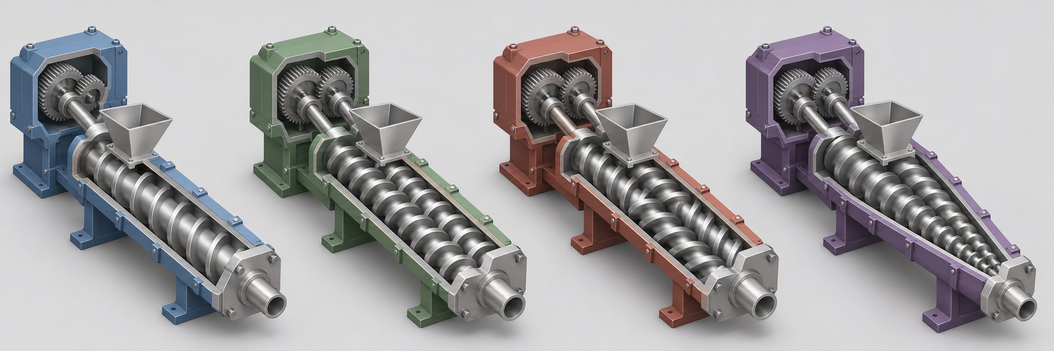
Stress patterns inside a gearbox shift dramatically depending on whether rotational force travels through one shaft or two — and the geometry of those shafts matters just as much as their number. Each extruder architecture transmits, distributes, and absorbs torque in a fundamentally different way, which shapes everything from gearbox complexity to the types of products a machine can efficiently produce. Yet no single reference compares these torque profiles side by side. The breakdown below fills that gap.
Single-Screw Extruder Torque Characteristics
A single-screw extruder channels all rotational force through one shaft, one set of gears, and one thrust bearing assembly. This simplicity keeps gearbox design compact and cost-effective, but it also means every Newton-meter of resistance the melt generates concentrates on a single mechanical path. If the process demands spike — say, during a cold-start or a sudden feed surge — there is no second shaft to share the load.
Extruder single screw torque demand is governed primarily by drag flow. The polymer advances because friction between the barrel wall and the material exceeds friction between the material and the screw. That drag-flow mechanism means torque scales with two geometric factors above all others: screw diameter and channel depth. A larger diameter sweeps more material per revolution, increasing resistance. Deeper channels hold more polymer in the compression and metering zones, adding to the shear load. For applications like pipe, profile, or sheet extrusion — where a single-screw platform already matches the process requirements — this architecture delivers reliable torque transmission without the added cost and complexity of a twin-shaft drivetrain.
Co-Rotating Twin-Screw Torque Profiles
Co-rotating intermeshing twin screws split total motor torque across two parallel shafts turning in the same direction. This division immediately doubles the surface area transmitting rotational force into the melt, enabling a higher specific torque density (Nm/cm3) relative to the machine's footprint. The result? More processing intensity packed into a smaller envelope — a key reason torque-optimized extruders in compounding plants frequently rely on co-rotating designs.
The critical trade-off here is the OD/ID ratio — the outer diameter of the screw flights divided by the inner diameter of the screw root. Increasing this ratio opens up more free volume inside the barrel, boosting throughput capacity and improving material intake. However, a higher OD/ID ratio simultaneously reduces the root diameter of the shaft, which is the very structure responsible for transmitting torque. Push the ratio too far, and the shaft cannot safely carry the rotational load without risking fatigue or deflection.
Modern co-rotating machines have evolved significantly in how they manage this balance. Industry classifications now range from standard-torque platforms (roughly 5.0-6.3 Nm/cm3) through high-torque designs (7.5-9.2 Nm/cm3) and into super-high-torque territory (10.6-12.8 Nm/cm3 and above), with operating speeds reaching 600-900 RPM. These gains come from advances in gearbox metallurgy, bearing technology, and shaft geometry — not simply by adding bigger motors. For a torque-optimized cable extruding line manufacturer, selecting the right tier directly determines whether the equipment can handle high-filler cable compounds without constant overload faults.
Counter-Rotating and Conical Twin-Screw Torque Considerations
Counter-rotating parallel twin screws turn in opposite directions, creating enclosed C-shaped melt chambers between the flights. This geometry generates high pressure with comparatively gentle shear — useful for heat-sensitive materials like rigid PVC — but the opposing rotation directions impose complex axial and radial loads on the gearbox, demanding robust bearing arrangements.
Conical twin-screw extruders take a different structural approach entirely. Imagine two screws that taper from a large diameter at the feed end to a smaller diameter at the discharge. The wider feed section does two things simultaneously: it provides generous free volume for solids intake and a large-diameter root capable of high torque transmission. As material advances toward the narrower discharge end, natural compression builds melt pressure efficiently. This tapered layout means the extruder single screw torque concentration problem is partly solved by geometry — the heaviest torque loads occur where the shaft is thickest.
Heavy-duty torque transmission systems in conical designs handle the asymmetric loading that arises because each screw section operates at a different effective diameter. These machines typically run at lower speeds — often 30-150 RPM — generating high torque without excessive shear heating. That combination makes them a staple for PVC pipe lines, wood-plastic composites, and high-calcium-carbonate-filled compounds where thermal sensitivity limits processing speed. A torque-optimized cable extruding line designed around PVC sheathing, for example, often benefits from this architecture precisely because it delivers the needed force without overheating the compound.
| Extruder Type | Torque Transmission Path | Typical Specific Torque Range | Key Design Constraint | Best-Suited Applications |
|---|---|---|---|---|
| Single-Screw | Motor → gearbox → single shaft & thrust bearing | Defined by screw diameter and motor/gearbox pairing (raw Nm; specific torque metric not standard) | All rotational stress on one shaft and one thrust bearing set | Pipe, profile, sheet, film extrusion; wire coating |
| Co-Rotating Twin-Screw | Motor → distribution gearbox → two parallel shafts (same direction) | ~5-13+ Nm/cm3 (standard to super-high torque tiers) | OD/ID ratio limits shaft diameter available for torque; compact centerline spacing constrains gear/bearing size | Compounding, masterbatch, reactive extrusion, devolatilization |
| Counter-Rotating Parallel Twin-Screw | Motor → gearbox → two parallel shafts (opposite direction) | Generally lower specific torque than co-rotating; process-dependent | Opposing rotation creates complex axial loads; limited intermeshing overlap at high speed | PVC pipe and profile, calender feeding |
| Conical Twin-Screw | Motor → gearbox → two tapered shafts (counter-rotating) | High absolute torque at feed end; specific torque favored by large root diameter | Fixed taper geometry limits L/D flexibility; asymmetric loading on bearings | Rigid PVC extrusion, WPC, high-CaCO3 compounds, heat-sensitive formulations |
Each architecture represents a different engineering answer to the same question: how do you get enough rotational force into the polymer without exceeding the mechanical limits of shafts, bearings, and gears? The answer depends on your material. And as you'll discover, the polymer itself has strong opinions about how much torque it demands — opinions shaped by melt viscosity, filler content, and processing temperature window.
How Material Properties Drive Torque Demand
A machine's torque rating is fixed the day it ships from the factory. The material you feed into it, however, changes from batch to batch, formulation to formulation, and sometimes bag to bag. That asymmetry is why material properties — not motor size or gearbox model — are the starting point for every meaningful torque analysis. Two extruders with identical drivetrains can show wildly different torque readings simply because one processes LDPE film resin while the other handles a 40% calcium-carbonate-filled HDPE compound. Understanding why those readings diverge gives process engineers the insight they need to prevent overload events before they happen.
Polymer Melt Viscosity and Torque Demand
Viscosity is the single largest material-side driver of extruder torque. When a screw rotates inside a barrel full of molten polymer, it must continuously shear the melt film trapped between the screw root and the barrel wall. The force required to sustain that shearing rises directly with the melt's resistance to flow — its viscosity. High-viscosity polymers fight back harder, demanding more rotational force from the drivetrain.
Consider the difference between two common polyethylenes. A standard LDPE with a melt index around 2.0 g/10 min flows relatively easily, keeping torque modest across a wide speed range. Switch to a high-molecular-weight bimodal HDPE with a melt index of 0.06, and things change dramatically. As extrusion expert Jim Frankland has documented, that kind of material swap can increase melt viscosity by roughly 83% at the same shear rate and temperature — translating almost directly into an 83% jump in the power needed to turn the screw. The additional energy doesn't vanish; it converts to heat inside the melt, raising discharge temperature beyond what downstream cooling can handle.
What makes this even trickier is that polymers are non-Newtonian. Their viscosity shifts with both temperature and shear rate — so the torque demand at startup (low temperature, low shear rate) can look nothing like the demand at full production speed. You can't rely on melt index alone to predict the difference. In Frankland's example, the melt index ratio between the two HDPEs was nearly 6:1, yet the actual viscosity ratio was only 1.83:1. Making processing decisions from melt index numbers without consulting full shear-rate/viscosity curves leads to large errors in expected torque behavior.
Low-viscosity melts present a different challenge. They flow easily, reducing the shear torque component — but achieving equivalent mixing or dispersion quality may require higher screw speeds, shifting the operating point along the torque-speed curve. A nylon 6 melt, for instance, offers lower viscous resistance than polycarbonate, yet the compounder may need to run the screws faster to achieve the same distributive mixing result. The torque per revolution drops, but total power consumption (and the risk of exceeding speed-dependent torque limits) can climb.
Filler Loading and Reinforcement Effects on Torque
Imagine stirring honey with a spoon — manageable. Now stir honey packed with sand and short glass fibers. The resistance your wrist feels jumps dramatically, and the same principle applies inside an extruder barrel. Mineral fillers and fiber reinforcements increase the apparent viscosity of the melt, and that increase compounds with loading level.
Mineral fillers such as calcium carbonate (CaCO3) and talc are among the most common torque-raising additives. According to material-specific torque data, a compound with 40%+ CaCO3 filler can exhibit a relative torque index of 3.0 to 5.0 compared to a baseline LDPE — meaning the drivetrain must deliver three to five times the rotational force just to maintain the same screw speed. Wood-plastic composites (WPC) at 50%+ wood fiber loading push that index even higher, reaching 4.5 to 6.5 times baseline. For a twin screw extruder torque calculation, these multipliers are not optional safety cushions; they represent real, measurable loads that the gearbox must sustain continuously.
Fiber reinforcements — glass fiber, carbon fiber, natural fibers — add a further complication. Unlike spherical mineral particles that increase viscosity relatively uniformly, fibers create directional resistance. They align, tangle, and bridge across screw channels, generating localized torque spikes that are harder to predict from bulk viscosity measurements alone. Glass-fiber-filled compounds (typically 30-50% by weight) carry a relative torque index of 3.5 to 5.5, and the recommended service factor for gearbox sizing climbs to 2.0-2.5 to absorb those spikes safely.
Moisture content adds yet another layer. Hygroscopic polymers like nylon, PET, and polycarbonate absorb atmospheric moisture that must be driven off during processing. In the devolatilization zone of a twin-screw extruder, the energy needed to vaporize that moisture increases both the thermal and mechanical load on the screw — effectively raising torque demand in a zone that engineers sometimes overlook during initial process design. Inadequately dried nylon containing 0.2-0.3% moisture, for example, generates noticeably higher torque readings than properly dried material at the same screw speed.
Matching Machine Torque Capacity to Material Requirements
Here is where many production teams get the sequence backward. They select a machine based on screw diameter and throughput rate, then discover during trials that the material's torque demand overwhelms the drivetrain. The correct approach flips the order: characterize the material first, calculate the expected torque demand, and then verify that the machine's rated capacity provides adequate headroom.
What does "adequate headroom" look like in practice? The material torque demand at steady-state running conditions should land between 50% and 85% of the gearbox's continuous rated torque. Running consistently above 85% leaves no margin for the inevitable process variations — a slightly cooler barrel zone, a batch of resin with higher molecular weight, a filler that arrives with elevated moisture. Running below 30% suggests the machine is significantly over-specified, wasting capital and potentially operating the gearbox outside its optimal efficiency range.
The following factors each push torque demand upward. When multiple factors combine — as they frequently do in real production — the effects stack:
- High melt viscosity — high-molecular-weight resins, low-melt-index grades, and inherently viscous polymers like rigid PVC or polycarbonate
- High filler loading — calcium carbonate, talc, barium sulfate, or other mineral fillers above 20-30% by weight
- High fiber content — glass fiber, carbon fiber, or natural fiber reinforcements, especially at loadings above 30%
- Moisture in the feed — undried hygroscopic polymers requiring in-barrel devolatilization
- Reactive processing additives — peroxides, silane coupling agents, or chain extenders that increase melt viscosity during processing
- Narrow processing temperature windows — materials like rigid PVC or certain biopolymers where lowering temperature to avoid degradation simultaneously raises viscosity and torque
Ignoring any of these material-driven factors is one of the most common root causes behind recurring torque overload alarms and premature gearbox wear. A gearbox sized for neat polypropylene pellets will not survive a shift to 40% talc-filled PP without a thorough re-evaluation of the torque budget — including cold-start peaks, which for filled compounds can reach 7 to 15 times the baseline running torque.
Material properties set the torque floor. The screw design determines how efficiently — or inefficiently — that torque is distributed along the barrel. Flight geometry, compression ratios, and mixing elements each shape the torque profile in ways that experienced engineers learn to manipulate deliberately, turning screw configuration into a powerful tool for managing the very demands that materials impose.
How Screw Design Elements Influence Torque Requirements
Flight depth, compression ratio, and mixing-element geometry are the levers that translate material resistance into a torque profile the drivetrain actually sees. Two formulations with identical viscosity curves can impose vastly different loads on the gearbox if the screws underneath them are configured differently. That makes screw design the single most controllable variable in managing extruder torque after the material has been specified. Yet many production teams treat screw configuration as a fixed feature of the machine rather than an engineering tool they can adjust. The sections below show exactly how each element type shapes torque demand — and where experienced engineers find room to optimize.
Flight Geometry and Compression Ratio Effects
Picture the feed zone of a single-screw extruder. Pellets tumble into deep, wide channels that grip solids and push them forward with relatively low resistance. Torque demand in this zone stays moderate because the material hasn't melted yet and the deep flights don't force it through tight gaps. Move downstream to the metering zone, where the channel is much shallower, and the story changes. The polymer is now a viscous melt being sheared across a thin film between the screw root and the barrel wall. Shallower flights mean higher shear rates, more viscous resistance, and — inevitably — more torque required from the drivetrain.
The compression ratio — defined as the feed-zone channel depth divided by the metering-zone channel depth — quantifies this transition. A screw with a 3:1 compression ratio reduces the available channel space by two-thirds as material travels from feed to metering. That compression does the critical work of melting and densifying the polymer, but it also concentrates a significant portion of the total torque demand in the compression zone. Higher ratios generate more pressure and more shear in a shorter axial distance, creating a steeper torque peak. Lower ratios spread the compression more gradually, distributing the mechanical load over a longer section of barrel.
For operators working with smaller-scale systems — including 3D printer extruder torque requirements — these principles apply at a different scale but follow the same physics. A desktop FDM extruder with a short melt zone and aggressive compression may demand more motor torque than a design with a gentler transition. In fact, a common complaint in the 3D printing community is an extruder stepper skipping higher torque loads when filament diameter varies or when printing with high-viscosity materials like polycarbonate. The root cause is identical to what happens on an industrial line: the channel geometry forces the material through a restriction that exceeds the motor's available rotational force.
Adjusting flight depth isn't just about changing one number on a drawing. Deeper metering channels reduce shear intensity and torque but may compromise melt homogeneity and pressure generation. Shallower channels improve mixing quality and die pressure stability but raise the torque floor. Engineers walk this tightrope every time they specify a new screw — or troubleshoot one that trips torque alarms during production.
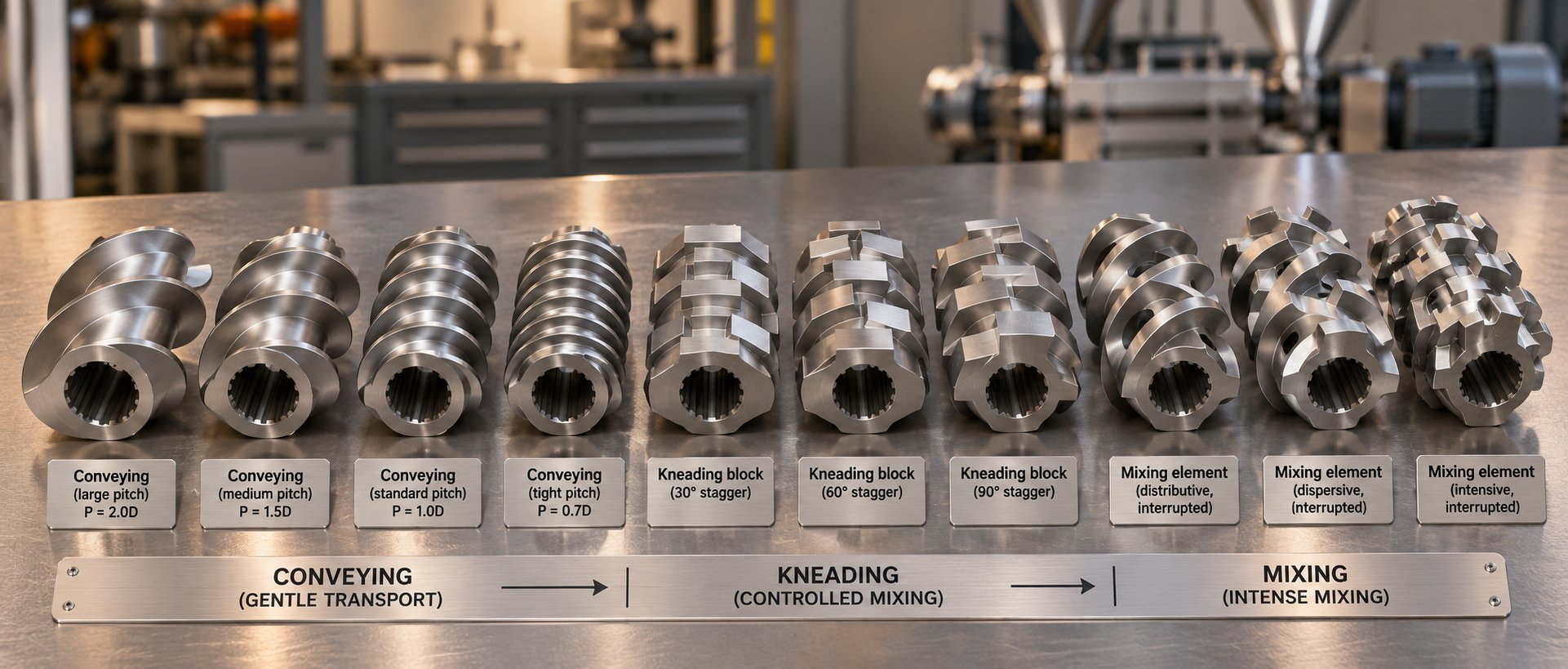
Kneading Blocks and Mixing Elements in Twin Screws
If flight geometry is the torque dial for single-screw extruders, kneading blocks are the torque amplifier for twin-screw systems. These multi-disc elements sit on the splined shaft and create intense flow disruption that no conveying element can match. Their three defining variables — disc width, block length, and stagger angle — give process engineers fine-grained control over how much rotational resistance the melt imposes at any point along the barrel.
Stagger angle is the dominant factor. According to CPM's twin-screw engineering guide, low stagger angles promote forward pumping with moderate shear, favoring distributive mixing. As the angle increases, net forward conveying drops, back-mixing intensifies, and local shear stress climbs sharply. At 90 degrees — the so-called neutral kneading block — forward conveyance effectively stops. Material oscillates back and forth across the discs, residence time spikes, and peak torque demand in that zone can exceed any other section of the screw by a wide margin.
Reverse kneading blocks push this even further. They actively oppose the direction of material flow, creating a pressure dam upstream that generates extreme shear and long local residence times. These blocks are powerful tools for dispersive mixing and melt sealing before vent ports, but as the NC State Extension publication on screw profile design notes, the length of reverse elements is typically kept shorter than the screw diameter to prevent excessive pressure peaks and strain on the material — and, by extension, on the drivetrain.
Disc width adds another layer. Narrower kneading discs create more frequent changes in the cross-sectional flow pattern along a shorter axial distance. Each transition generates local pressure fluctuations and extensional flow that intensify dispersive mixing and deagglomeration — ideal for breaking pigment clusters or carbon black agglomerates. But those same fluctuations translate into higher and more variable torque loading. Wider discs smooth out the flow, favor distributive mixing, and produce a gentler, more predictable torque signature.
Beyond kneading blocks, several other mixing element designs redistribute torque by splitting and recombining melt streams rather than shearing them aggressively. Maddock mixers (also called LeRoy mixers) use barrier flights to force melt through a narrow gap, creating a controlled shear zone. Saxton mixers employ multiple interrupted flights that repeatedly divide and restack the flow. Cavity transfer mixers use hemispherical cavities in both the screw and barrel that hand melt back and forth between rotating and stationary surfaces. Each design achieves mixing through a different mechanism, and each imposes a different torque profile — making element selection a genuinely engineering-level decision rather than a catalog exercise. (These mixer types are discussed here as engineering-inquiry topics for educational context.)
The 3D printer extruder motor torque challenge has its own version of this problem. While desktop systems rarely use modular kneading blocks, some advanced filament extruders and pellet-fed 3D print extruder torque setups incorporate mixing zones to homogenize color or additives. When those zones are too restrictive, the stepper or servo motor stalls — the small-scale equivalent of an industrial torque overload alarm.
Balancing Torque Distribution Through Screw Configuration
Experienced screw designers don't just pick elements that deliver enough mixing. They sequence those elements to avoid concentrating torque demand in a single zone, spreading the mechanical workload along the full barrel length. The goal is a torque profile that ramps gradually rather than spiking — because spikes are what break shear pins, fatigue shafts, and wear gearbox bearings prematurely.
Think of it like planning a road trip over mountain passes. You wouldn't schedule three steep climbs back to back with no recovery stretches in between. Similarly, a well-designed twin-screw profile typically alternates intense kneading sections with conveying elements that relieve pressure and allow material to move forward under lower stress. CPM's engineering guidance confirms that conveying elements set fill level and build pressure between mixing zones, functioning as the recovery stretches that keep the overall torque envelope manageable.
The following screw design parameters each influence the torque profile and should be evaluated as a system, not in isolation:
- Flight depth — deeper channels reduce shear and torque in conveying zones; shallower channels increase both
- Compression ratio — higher ratios concentrate more torque in the compression zone
- Number of flights — multi-flighted screws distribute material over more shearing surfaces, altering the per-flight torque contribution
- Kneading block width and stagger angle — narrower discs and steeper angles raise peak torque; wider discs and shallow angles smooth it
- Mixing section type and length — dispersive elements demand more torque than distributive elements of equivalent length
- Screw pitch — tighter pitch increases compression and pressure buildup, raising torque in that zone
Getting this balance right requires more than textbook knowledge — it demands application-specific analysis of flight depths, compression ratios, mixing sections, materials, and surface treatments. This is exactly the type of engineering evaluation that custom screw design services such as NANHAIYA's provide, helping teams balance plasticizing, mixing, and torque demands before committing to manufacturing. When standard catalog screws produce persistent torque peaks or inconsistent product quality, a purpose-built configuration designed around the actual polymer, filler system, and machine constraints often resolves problems that process parameter adjustments alone cannot.
Screw geometry shapes where torque acts along the barrel. But screw speed determines how much torque the motor can deliver at any given operating point — and that relationship is anything but linear. The interplay between torque, speed, and the gearbox sitting between them introduces constraints that many operators discover only after pushing the RPM dial too far.
Torque-Speed Relationships and the Extruder Drivetrain
Pushing the screw speed dial higher feels like a straightforward way to boost throughput. More revolutions per minute means more polymer moves through the die per hour — right? In theory, yes. In practice, the relationship between speed and available rotational force follows rules that catch operators off guard. At constant power, increasing speed reduces the torque the motor can deliver to the screw. Push RPM high enough, and the drivetrain runs out of twisting force before it runs out of kilowatts. Understanding this trade-off — and knowing where the gearbox fits into the picture — separates engineers who optimize extrusion lines from those who chase alarms.
Understanding Torque-Speed Curves for Extruder Motors
The physics is clean and unforgiving. At constant power output, torque and speed sit on opposite ends of a seesaw:
Torque = Power / Angular Velocity
Double the speed, and available torque drops by half — assuming power stays the same. This inverse relationship is baked into every AC motor that drives an extruder. But modern extrusion lines rarely run motors at a single fixed speed. Instead, they use variable-frequency drives (VFDs) to adjust motor speed continuously, and VFDs reshape the torque-speed curve into two distinct operating regions.
Below the motor's base speed (the nameplate RPM at rated frequency, typically 50 or 60 Hz), the VFD maintains a constant voltage-to-frequency ratio. In this zone, the motor delivers essentially constant torque regardless of speed. An extruder running its screw at 40% of maximum RPM has just as much rotational force available as it does at 80% — a crucial advantage during startup and low-speed processing of high-viscosity compounds. As ABB's inverter-duty motor documentation explains, extruders fall squarely into the constant-torque application category, alongside conveyors and mixers, because the load demands full rotational force even at reduced speeds.
Above base speed, things shift. The VFD can increase frequency beyond the nameplate rating, pushing the motor faster, but voltage has already reached its maximum. Power plateaus, and the motor enters a constant-power region where every additional RPM comes at the direct expense of available torque. An operator who cranks screw speed 20% above the design point to chase a throughput target may discover that the torque percentage on the HMI climbs sharply — not because the material got harder to process, but because the motor simply has less twisting force to offer at that speed.
Why does this matter on the production floor? Because torque overload alarms triggered at high screw speeds are frequently misdiagnosed as material problems or screw-design issues, when the real culprit is the motor operating beyond its constant-torque region. Checking whether the commanded speed exceeds the VFD's base-speed setting is often the fastest diagnostic step — and the one most frequently skipped.
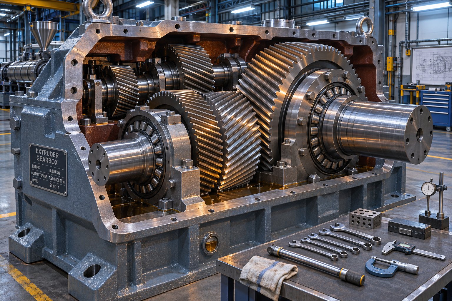
Gearbox Torque Multiplication and Limits
Between the motor shaft and the screw sits the component that transforms a high-speed, moderate-torque motor output into the low-speed, high-torque rotation the screw needs: the gearbox. Its job is straightforward multiplication. A gearbox with a 15:1 ratio takes the motor's output speed and divides it by 15 while multiplying the torque by roughly the same factor (minus efficiency losses at each gear stage).
Sounds like the gearbox just amplifies whatever the motor provides. In reality, the gearbox has its own hard ceiling — and that ceiling is frequently lower than the motor's theoretical maximum output. This is especially true in twin-screw extruders where compact shaft spacing constrains gear and bearing sizes, physically limiting how much torque the gear teeth and output bearings can transmit without fatigue or failure. Two co-rotating shafts sitting just centimeters apart leave minimal room for the large-diameter gears and heavy-duty bearings that high torque demands.
Consider a practical scenario. A 200 kW motor driving through a 12:1 gearbox could theoretically deliver over 19,000 Nm at the screw shaft (assuming 95% gearbox efficiency and a screw speed of about 120 RPM). But if the gearbox is rated for only 15,000 Nm continuous duty, that theoretical motor capacity is irrelevant — the gearbox becomes the bottleneck. This mismatch is more common than you might expect, particularly when plants retrofit larger motors onto existing extruders without upgrading the gearbox simultaneously.
Gearbox efficiency losses compound through each reduction stage. A three-stage gearbox at 97% efficiency per stage delivers roughly 91% overall, meaning nearly one-tenth of the motor's power converts to heat inside the gearbox housing rather than useful screw torque. That lost energy must be dissipated through the lubrication and cooling system — and if the cooling capacity falls short, oil temperature rises, viscosity drops, bearing film thickness thins, and the wear cycle accelerates. Undersized cooling is a silent contributor to gearbox failures that get blamed on torque overload.
Sizing the Complete Drivetrain for Torque Headroom
Every drivetrain is only as strong as its weakest link. A massive motor paired with an undersized gearbox wastes capital on power that can never reach the screw. An over-built gearbox coupled to a motor that can't deliver enough power at the target RPM leaves torque capacity stranded. The engineering discipline is to identify the bottleneck before commissioning and ensure every component in the chain has adequate margin above peak process demand.
The gearbox torque rating, not the motor nameplate power, typically determines the true torque ceiling of an extruder. Specifying based on motor kilowatts alone is the most common sizing error in drivetrain selection.
A reliable guideline from gearbox engineering practice: run at 80% of the gearbox's continuous torque rating and 80% of maximum speed. That 20% margin on each axis provides headroom for cold-start transients, batch-to-batch material variation, and the inevitable process excursions that production reality introduces. For machines processing highly filled or glass-fiber-reinforced compounds — the types of formulations that define the best high torque series twin screw extruder applications — service factors of 2.0 or higher may be warranted to absorb the torque spikes discussed in the material-properties section.
The following sequence keeps the sizing process disciplined and prevents the common mistake of anchoring on motor power first:
- Determine process torque demand — use the material's viscosity profile, filler loading, and screw geometry to calculate the torque the process will require at the target screw speed and throughput. The formulas from Chapter 2 provide the quantitative foundation.
- Apply a safety margin — account for cold-start peaks (which can exceed steady-state torque by 20-40%), batch variability, and any anticipated future formulation changes. For demanding compounds, this margin may double the steady-state figure.
- Select a gearbox with adequate continuous torque rating — match the gearbox to the margined torque requirement. Compare on continuous duty rating, not peak or intermittent specifications. For twin-screw systems, verify the per-shaft rating, not just total torque.
- Verify the motor can deliver required power at the target RPM — back-calculate the power needed using P = T x 2π x N / 60, then confirm the motor can supply that power within its constant-torque region. If the target speed falls above base speed, recalculate available torque in the constant-power region.
- Confirm thrust bearing capacity — the screw generates axial thrust as it pushes melt against die resistance. Thrust bearing capacity often limits gearbox life before torque capacity does, so verify that the bearing's rated life at the expected axial load meets or exceeds the maintenance interval target.
Skipping any of these steps — or performing them out of order — risks a drivetrain where one component is chronically overloaded while others coast below capacity. The best super high torque series twin screw extruder platforms on the market achieve their performance precisely because motor, gearbox, bearings, and screw geometry are sized as an integrated system rather than selected piecemeal from separate catalogs.
With the drivetrain framework in place, the next practical question becomes: how do you read and compare the torque specifications that manufacturers actually publish? Nameplate numbers don't always mean what they appear to — and the gap between continuous, peak, and specific torque ratings holds traps for engineers who haven't learned where to look.
Torque Specification Reference for Extruder Selection
Specification sheets are where drivetrain theory meets purchasing reality. Every extruder manufacturer publishes torque numbers, but the way those numbers are presented — and what they actually represent — varies enough to trip up engineers who compare across brands without a common framework. A 12,000 Nm rating on one datasheet may not mean the same thing as a 12,000 Nm rating on another. Knowing how torque specifications scale with machine size, how classification tiers work, and which numbers to normalize before comparing gives you the clarity to evaluate equipment on its actual capability rather than its marketing emphasis.
Typical Torque Ranges by Extruder Size Class
Torque demand doesn't grow linearly with screw diameter — it scales roughly with the cube of the diameter ratio. A 90 mm screw requires approximately 3.4 times more torque than a 60 mm screw under the same material and speed conditions. That cubic relationship explains why large production extruders carry gearbox ratings that dwarf their lab-scale counterparts, even when both machines process the same resin.
For single-screw extruders, the practical torque envelope widens dramatically as diameter increases. Small lab and pilot units with 25 mm screws typically operate in the 200-1,200 Nm range depending on material, driven by motors in the 2.2-7.5 kW class. Mid-range production machines at 60 mm jump to 3,000-15,000 Nm, while heavy-duty lines at 150 mm can demand 40,000-230,000 Nm — the higher end reserved for viscous materials like rigid PVC and highly filled compounds. The material being processed matters as much as the screw size: an HDPE pipe line at 90 mm might draw 9,000-22,000 Nm, while the same diameter running rigid PVC profiles could pull 18,000-50,000 Nm.
For twin-screw extruders, raw Nm values become less meaningful as a comparison tool. The industry instead relies on specific torque (Nm/cm3) — torque per shaft divided by the cube of the screw diameter (or centerline distance, depending on the convention). This normalized metric lets you compare a compact 35 mm compounder to a 75 mm production machine on level ground. The classification tiers that have become standard across the industry break down as follows:
- Standard torque — roughly 8.8-10 Nm/cm3, suitable for conventional filling, blending, and coloring operations that cover approximately 70% of traditional plastic modification work
- High torque — approximately 11-13.5 Nm/cm3, capable of handling high-filler formulations (up to 50% mineral loading), glass-fiber reinforcement, and engineering plastics that overwhelm standard platforms
- Super-high torque — 15 Nm/cm3 and above, representing the current cutting-edge. These machines target highly viscous elastomers, ceramic feedstocks, reactive extrusion, and direct extrusion processes that bypass the granulation step entirely
When evaluating whether to buy high torques twin screw extruder equipment or invest in a super-high-torque platform, the decision hinges on your formulation portfolio. If 80% of your production involves standard polyolefin compounds with moderate filler levels, a high-torque machine provides comfortable headroom without the capital premium of a super-high-torque system. But if your roadmap includes challenging materials — biodegradable polymers, high-loading mineral compounds, or reactive chemistries — the best super-high torque series twin screw extruder options justify their cost by keeping the process well within the gearbox's safe operating window even under worst-case conditions.
Reading and Comparing Torque Specifications
Sounds straightforward — just compare the Nm numbers on two datasheets, right? Not quite. Extruder specification sheets contain several torque-related values, and confusing them leads to costly mismatches.
The first distinction is continuous torque rating versus peak torque. The continuous (or nominal) rating is the torque the gearbox can deliver indefinitely under normal operating conditions. Peak torque — sometimes labeled "overload" — is a short-duration maximum, typically 150% to 250% of the continuous rating, sustained for only seconds at a time. Some manufacturers highlight the peak number because it's more impressive; always verify you're comparing continuous-to-continuous.
The second distinction applies specifically to twin-screw machines: torque per shaft versus total torque. A datasheet quoting 10,000 Nm total for a co-rotating twin-screw system means each shaft handles only 5,000 Nm. If a competing manufacturer quotes 6,000 Nm per shaft, that machine actually delivers 12,000 Nm total — 20% more capacity despite the smaller headline number. Always confirm whether the figure is per-shaft or combined before drawing conclusions.
Third, the OD/ID ratio directly affects specific torque density in twin-screw machines. A higher OD/ID ratio increases free volume (good for throughput and low-bulk-density feeds) but shrinks the shaft root available for torque transmission. Two machines with identical specific torque ratings but different OD/ID ratios — say 1.55 versus 1.80 — offer very different balances between volume capacity and torque headroom. The machine with the lower ratio packs more shaft strength per unit of screw cross-section, while the higher-ratio machine trades some of that strength for greater volumetric intake. Neither is inherently superior; the right choice depends on whether your process is torque-limited or volume-limited.
A thermal torque rating also appears on some datasheets — the maximum continuous torque limited by the gearbox's ability to dissipate heat rather than its mechanical strength. In hot climates or poorly ventilated installations, this thermal ceiling can drop below the mechanical rating, effectively becoming the governing limit. If your plant operates in tropical conditions, check both values and use whichever is lower.
The reference table below provides a framework for organizing these specifications across the four major extruder architectures. Use it as a template when collecting and normalizing vendor data for side-by-side evaluation.
| Extruder Class | Screw Diameter Range | Torque Classification | Specific Torque Metric | Typical Application |
|---|---|---|---|---|
| Single-Screw | 25 mm - 150 mm+ | Rated by absolute Nm (classification tiers not standard) | Not commonly used; compare via raw Nm at matched screw diameter and material | Pipe, profile, sheet, film, wire coating |
| Co-Rotating Twin-Screw | 20 mm - 135 mm+ | Standard (~8.8-10 Nm/cm3), High (~11-13.5 Nm/cm3), Super-High (15+ Nm/cm3) | Nm/cm3 (per-shaft torque / screw diameter3) | Compounding, masterbatch, reactive extrusion, devolatilization |
| Counter-Rotating Parallel Twin-Screw | 35 mm - 173 mm+ | Typically standard to high; application-specific sizing | Nm/cm3 where published; often specified as raw Nm per shaft | PVC pipe and profile, calender feeding |
| Conical Twin-Screw | 35/70 mm - 80/156 mm+ (small end/large end) | High absolute torque at feed end; taper geometry favors torque transmission | Less standardized; compare at matched taper ratio and material | Rigid PVC, WPC, high-CaCO3 compounds |
Comparing across manufacturers without normalizing to specific torque is like comparing fuel efficiency across vehicles without accounting for weight — the numbers look meaningful but lead to flawed decisions. An engineer evaluating whether to buy super high torque series twin screw extruder equipment from different vendors should convert every quoted value to the same basis: per-shaft, continuous, at the same speed and diameter convention. Only then does the comparison reveal which machine genuinely offers more processing headroom and which one simply presents its numbers more favorably.
Specifications tell you what the machine can deliver. What happens when the process pushes past those limits — or when something goes wrong mid-production — is an entirely different challenge. Torque overload alarms, unexplained fluctuations, and creeping gearbox wear are the daily realities that turn clean datasheet numbers into messy production problems.
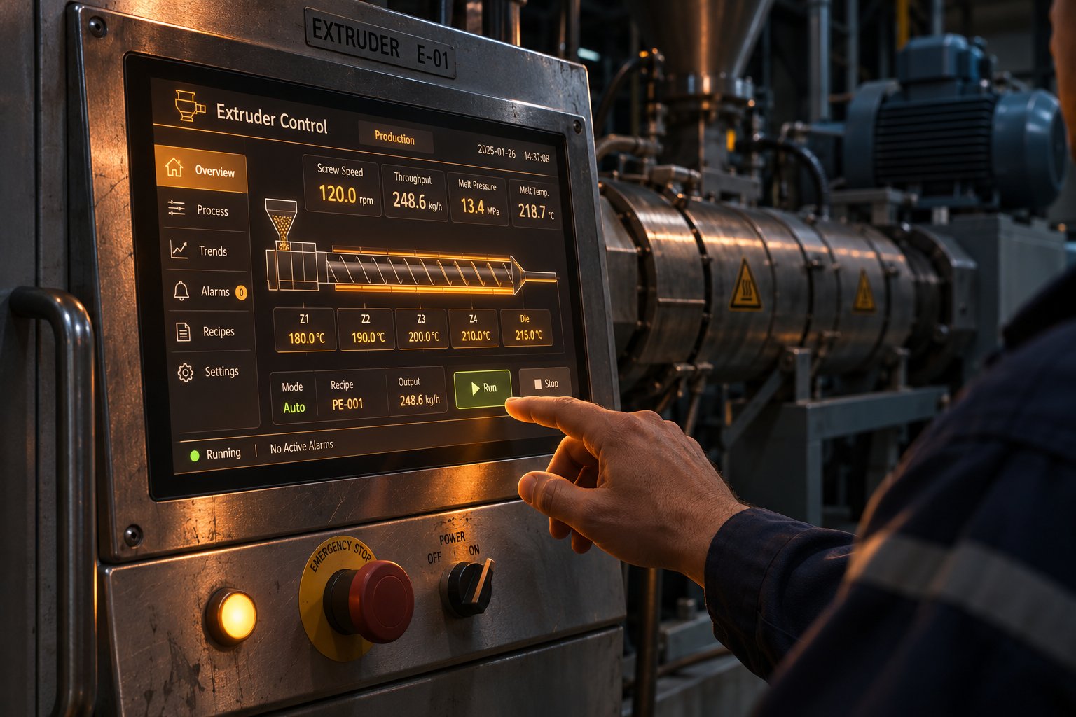
Troubleshooting Common Extruder Torque Problems
Clean datasheet numbers and well-sized drivetrains don't immunize a production line against torque problems. Alarms fire at 2 AM. Gearbox temperatures creep upward over weeks without anyone noticing. A material change that worked fine in the pilot lab sends the HMI into overload protection on the first full-scale run. These are the realities plant engineers and operators face daily, yet torque-related troubleshooting remains the least-documented area in extrusion literature. The sections below close that gap with a systematic approach to diagnosing, understanding, and preventing the most common torque faults across both single-screw and twin-screw platforms.
Diagnosing Torque Overload Alarms
When the torque display climbs past the alarm threshold and the machine shuts down, the instinct is to restart immediately. Resist that urge. A rushed restart without clearing the root cause risks secondary overload damage from material still packed inside the barrel. Instead, cut the feeder first, let the screw turn at low speed for three to five minutes to purge residual material, and then begin working through the diagnostic sequence.
The causes of torque overload cluster into four categories, and most production faults trace back to one of the first two:
- Inadequate barrel preheat — Starting the screw before all barrel zones have reached their setpoints forces the flights to push semi-solid polymer and unmelted pellets. The resistance is enormous. Low-temperature startup is the primary cause of sustained high torque, and the problem worsens in winter when ambient conditions slow the heating system.
- Excessive filler loading beyond design capacity — High-hardness inorganic fillers like calcium carbonate, talc, and glass fiber dramatically increase internal friction. When filler ratios creep above the level the screw configuration was designed to handle, torque rises steeply and may not stabilize even after full melting.
- Incorrect screw speed ramp rates — Jumping to full production speed before the material has reached a stable melt condition overloads the compression zone. A graded startup — low feed rate and low speed first, increasing step by step — avoids the transient torque peaks that trigger alarms.
- Degraded polymer or contaminated feed — Metal fragments, hard plastic chunks, or crosslinked gel particles create rigid resistance that the screw cannot shear through. Even small contaminants produce sharp, sudden torque spikes accompanied by abnormal gearbox noise.
- Worn screw or barrel increasing resistance — As screw flights and barrel liners wear, the gap widens, material leaks backward, and the screw must work harder to push the same throughput forward. The net result is gradually rising baseline torque over weeks or months.
Faced with an overload alarm, the following diagnostic steps move from the simplest checks to the most involved, allowing you to isolate the cause efficiently:
- Verify barrel zone temperatures have reached setpoints — Check every zone, not just the average. A single zone lagging 30-40 degrees Celsius below its target can create a plug of unmelted material that spikes torque across the entire barrel.
- Check feed rate and filler ratio against the process sheet — Confirm that the gravimetric feeders are calibrated and that the current batch matches the approved formula. Even a 5% increase in filler loading can push torque from a comfortable 75% into the alarm range.
- Inspect the feed throat for bridging — Material bridging above the screw creates alternating starve-and-flood cycles that produce torque surges. Hopper bridging, variable bulk density, and moisture variation all contribute.
- Review recent screw or barrel maintenance records — Has the screw configuration changed? Were kneading blocks replaced with a different stagger angle? Was the barrel liner last measured for wear six months ago, or two years ago?
- Confirm gearbox oil temperature and level — Elevated oil temperature signals either excessive torque loading or inadequate cooling. Low oil level reduces lubrication film thickness, increasing mechanical resistance that masquerades as process torque. Deteriorated lubricating oil with impurities also raises transmission resistance, contributing to false high-torque readings.
Working through these five steps in order catches the majority of overload causes before you ever need to pull the screw for inspection. Only if the alarm persists after confirming clean material, correct temperatures, proper feed rates, and healthy gearbox oil should you escalate to a full mechanical teardown.
Understanding Torque Fluctuations During Processing
An overload alarm is dramatic — it stops the line. Torque fluctuations, by contrast, are subtle. The readout bounces around a moving average, the product looks mostly fine, and operators learn to ignore the variations. That's a mistake. The pattern of fluctuation tells a diagnostic story if you know how to read it.
Cyclic, repeating torque swings — a rhythmic rise and fall every few seconds — almost always point to inconsistent feeding. The screw alternates between being overfed and starved, and the torque follows the feed cycle faithfully. Feeder calibration errors, hopper bridging, and variable bulk density in the raw material are the usual suspects. In stable production, torque should fluctuate within a narrow band — smooth variation of 2-3% is normal. Repetitive spikes that exceed that band warrant immediate feeder inspection.
Erratic, non-repeating torque spikes suggest a different problem. Foreign material — metal particles, hard contaminants, or chunks of unmelted crosslinked polymer — creates sudden, unpredictable resistance as it passes through the compression zone. Unlike feed-related fluctuations, these spikes have no regular period. They appear randomly, sometimes violently enough to trip the overload threshold on a single event. Immediate shutdown and barrel inspection are recommended whenever sharp, isolated spikes appear alongside abnormal noise.
Gradual, trending torque increases over days or weeks tell yet another story: wear. As screw flights lose their sharp edges and barrel liners thin, conveying efficiency drops. The screw compensates by drawing more torque to maintain the same throughput. Monitoring torque trends over time — not just instantaneous values — provides one of the earliest warnings that screw or barrel replacement is approaching. A 5-10% upward drift in steady-state torque at unchanged process conditions is a strong signal to schedule a measurement inspection at the next planned shutdown.
Temperature imbalance across barrel zones can also drive torque instability. If one zone runs too cool, the melt in that section thickens, increasing local resistance and creating a torque bump that propagates downstream. Conversely, an overheated zone can cause the polymer to degrade or crosslink locally, generating hard spots that spike torque as they pass through kneading blocks or restrictive mixing elements. Verifying that all zone controllers are holding steady, with no offset between setpoint and actual temperature, eliminates this common contributor.
Preventing Torque-Related Equipment Damage
Can excessive torque actually damage an extruder? Absolutely — and the damage often progresses silently for weeks before becoming catastrophic. Understanding what sustained high-torque operation does to each drivetrain component helps justify the preventive practices that keep a line running reliably.
Gearbox bearing wear accelerates when torque consistently exceeds 85% of the continuous rating. Bearings designed for a 100,000-hour rated life under normal loads may last only a fraction of that under chronic overload because bearing life scales inversely with the cube of the applied load. A 20% torque increase, sustained over months, can cut bearing life roughly in half.
Shaft fatigue is insidious. Screw shafts endure millions of stress cycles per day. Each cycle at elevated torque pushes the shaft material closer to its fatigue limit. In a heavy duty torque transmission system in conical twin screw extruder designs, the tapered shafts are engineered to handle asymmetric loading, but even these robust configurations have finite fatigue budgets. Running continuously above the design envelope consumes that budget faster than any maintenance schedule can accommodate.
Coupling failure — where the motor shaft connects to the gearbox input — often serves as the first visible sign of chronic overtorque. Couplings absorb misalignment and shock loads, but they're not designed to be permanent energy sinks. Repeated torque transients wear coupling elements, introduce vibration, and eventually lead to complete disengagement during production.
Screw breakage is the worst-case outcome. Sustained overload can cause screw shaft deformation, gearbox tooth breakage, and motor winding burnout — failures that carry not just repair costs but weeks of lost production. In twin-screw systems, a broken screw can also damage the second screw and the barrel liner, turning a single component failure into a full-machine rebuild.
The table below consolidates the most common torque-related symptoms into a diagnostic reference. Use it as a starting checklist when torque behavior deviates from normal production patterns.
| Symptom | Likely Cause | Diagnostic Check | Corrective Action |
|---|---|---|---|
| Torque overload at startup | Cold barrel zones; unmelted material in the screw channels from previous shutdown | Verify all zone temperatures have reached setpoints; check soak time against standard operating procedure | Extend preheat time; purge at low speed before ramping to production; in winter environments, increase zone temps by 5-10 degrees Celsius above standard |
| Torque creep during production | Screw or barrel wear reducing conveying efficiency; gradually increasing filler ratio due to feeder drift; gearbox oil degradation raising mechanical resistance | Compare current steady-state torque to baseline from last known-good run; check feeder calibration; measure gearbox oil temperature and sample oil quality | Schedule screw/barrel measurement; recalibrate feeders; replace gearbox oil if degraded; replace worn screw elements and recalibrate assembly gap |
| Sharp, isolated torque spikes | Foreign contaminant (metal, hard plastic, crosslinked gel) entering the barrel; solid bed breakup in single-screw systems | Inspect feed material for contamination; check magnetic separators and screens upstream of the feed throat; review melt pressure trend for correlated spikes | Install or upgrade metal detectors and screening equipment; purge barrel and inspect screw for damage; address upstream contamination source |
| Cyclic torque fluctuation | Inconsistent feeding (surging); hopper bridging; variable bulk density or moisture in the feed material | Monitor feeder output rate vs. time; inspect hopper for bridging; test incoming material bulk density and moisture content | Recalibrate gravimetric feeders; install hopper agitators or vibrators; pre-dry hygroscopic materials; stabilize feed material quality |
| Sustained high torque without alarm | Material viscosity higher than specification (wrong grade, undried hygroscopic polymer); barrel temperature offset; die partially blocked | Confirm resin grade and lot against process sheet; verify barrel temps actual vs. setpoint across all zones; inspect die for carbonized buildup | Replace off-spec material; repair or recalibrate faulty zone heaters; clean die and breaker plate; adjust temperature profile to reduce melt viscosity |
A natural follow-up question: if torque spikes are inevitable in real production, what stops them from destroying the gearbox every time? The answer is mechanical safeguards — specifically, torque limiters and shear pins. Torque limiters are mechanical devices that disengage the drive when rotational force exceeds a preset threshold, preventing the spike from propagating through to the gearbox gears and screw shaft. Friction-type torque limiters slip and can be reset after the overload clears; shear-pin types sacrifice a replaceable pin that breaks to interrupt the drivetrain, requiring a brief shutdown to install a new pin before resuming production.
These safeguards are essential — but they are last-resort protection, not operating strategy. A line that regularly trips its torque limiter or shears pins has a process problem, a material problem, or a machine problem that the safeguard is merely masking. Each disengagement event subjects the drivetrain to a sudden load-unload cycle that stresses couplings and gear teeth. Torque limiters protect against catastrophic failure, but relying on them as routine operating protection accelerates the very wear they're designed to prevent. The correct response to frequent torque limiter activation is the same as for frequent overload alarms: work through the diagnostic checklist above, identify the root cause, and eliminate it.
This principle applies across all machine architectures. Whether you're running a compact single-screw pipe line or operating a heavy duty torque transmission system in conical twin screw extruder configurations built for high-calcium-carbonate PVC compounds, the safeguards serve the same function — buying you time to diagnose, not permission to ignore. A plant that tracks torque trends, maintains calibrated feeders, adheres to preheat protocols, and schedules wear inspections proactively will rarely see its torque limiters activate. That's the goal: make the safety net unnecessary by keeping the process within the drivetrain's engineered envelope.
Solving torque problems reactively — one alarm, one shear pin, one gearbox repair at a time — is expensive and disruptive. The more powerful approach is to design torque management into the process from the start, connecting material characterization, screw geometry, and drivetrain sizing into a single, deliberate engineering workflow.
Optimizing Screw Geometry for Torque-Efficient Extrusion
Reactive troubleshooting keeps a line running today. Proactive torque management keeps it running profitably for years. Every concept explored in the preceding sections — formulas, material viscosity curves, screw element sequencing, drivetrain sizing, and fault diagnostics — converges on a single engineering discipline: designing the process around torque from the very first specification meeting, not after the first overload alarm. The workflow below ties these threads into a repeatable methodology that any extrusion team can adopt, whether commissioning a new line or re-engineering an existing one that chronically underperforms.
A Systematic Approach to Torque-Aware Process Design
Think of torque-aware design as a chain of decisions where each link feeds the next. Skip a link — say, jumping straight to gearbox selection without first characterizing the material — and the chain breaks under the first real-world load. The sequence below keeps the engineering logic intact from material lab to production floor.
- Characterize the material fully — Gather shear-viscosity curves at processing-relevant temperatures and shear rates, not just melt index values. Document filler type, loading percentage, fiber aspect ratio, and moisture content. For reactive formulations, map the viscosity evolution as the reaction progresses. This data becomes the torque demand baseline.
- Calculate expected torque demand — Apply the formulas from the calculation fundamentals section: use T = (P × 9550) / N to frame the torque envelope, then cross-check with specific energy input (SEI) targets for the polymer family. For twin-screw applications, convert to per-shaft values and specific torque (Nm/cm³) to benchmark against machine classifications. Research on extrusion process optimization confirms that simulation-based torque prediction is far more reliable than trial-and-error, reducing commissioning time and protecting mechanical components from avoidable overloads.
- Verify machine torque capacity with adequate margin — Compare the calculated demand against the gearbox's continuous torque rating — not the peak or intermittent value. Apply the appropriate service factor: 1.5 for neat polymers, 2.0-2.5 for highly filled or fiber-reinforced compounds. Confirm that the motor delivers the required power within its constant-torque speed range, and that thrust bearings can sustain the expected axial load for the full maintenance interval.
- Design or select screw geometry to distribute torque efficiently — Sequence flight depths, compression ratios, kneading block configurations, and mixing sections so that no single barrel zone absorbs a disproportionate share of the total torque load. Alternate high-intensity mixing sections with conveying elements that relieve local pressure. For direct drive extruder torque applications where the motor couples to the screw without a gearbox speed reduction, screw geometry becomes even more critical because the motor must deliver full torque at screw speed with no mechanical multiplication.
- Validate with monitored trial runs — During commissioning, record torque percentage, melt temperature, melt pressure, and throughput simultaneously. Compare actual torque profiles against calculated predictions. Identify any zones where torque consistently exceeds expectations and adjust screw configuration, barrel temperatures, or feed rate accordingly.
- Establish torque baselines for ongoing monitoring — Document the steady-state torque reading for each approved product and formulation. These baselines become your early-warning system: a 5-10% drift signals screw wear, feeder drift, or material variation long before product quality visibly degrades.
This sequence mirrors what polymer extrusion scale-up research identifies as best practice — using process simulation and systematic optimization rather than reactive experimentation. Whether you're scaling from a China high torque series twin screw extruder pilot platform to full production or configuring a new conical line for PVC compounds, the workflow remains the same. Only the specific numbers change.
When to Consult Screw Design Engineering Support
Standard catalog screws handle a broad middle ground of common polymers and moderate filler loadings. But certain scenarios push beyond what off-the-shelf configurations can manage efficiently — and that's when purpose-engineered screw geometry becomes the difference between a line that runs at 70% torque and one that chronically hovers at 92%.
You'll recognize these scenarios on the plant floor:
- Processing a new polymer or compound formulation — Unfamiliar viscosity behavior, unusual filler systems, or reactive chemistries create torque profiles that no existing screw in your inventory was designed to handle. Guessing at element sequencing wastes trial material and risks gearbox damage.
- Scaling from pilot to production — A screw profile that works beautifully on a 26 mm lab compounder may distribute torque very differently on a 75 mm production machine. The cubic scaling of torque with diameter means small geometric mismatches amplify into large torque imbalances at full scale.
- Experiencing persistent torque-related quality issues — Unmelts, gel particles, inconsistent color dispersion, or degradation streaks often trace back to screw zones where torque is either concentrated too intensely (causing localized over-shearing) or spread too thinly (causing under-processing). Adjusting barrel temperatures or screw speed treats the symptom; re-engineering the screw profile addresses the cause.
- Upgrading to higher throughput targets — Increasing feed rate on an existing screw raises torque demand across every zone. If the current profile was already operating near the gearbox's safe window, the throughput increase may push it past the alarm threshold. A redesigned profile can redistribute the added load to keep the drivetrain within its envelope.
- Operating a heavy-duty torque transmission system in conical twin screw extruder lines — Conical geometries impose asymmetric torque distribution that standard parallel-screw design rules don't fully capture. The tapered screw profile must balance high-torque feed-end conveying against low-diameter discharge-end pressure generation, a challenge that benefits from specialized engineering analysis.
When torque challenges trace back to screw geometry — and the diagnostic checklist confirms that material, temperatures, and drivetrain are all within specification — consulting a custom screw design service is the logical next step. NANHAIYA's custom screw design service is built around exactly this type of analysis: its engineers review polymer behavior, machine dimensions, temperature limits, and production targets, then evaluate flight depths, compression ratios, mixing sections, materials, and surface treatments to balance plasticizing, mixing, and processing demands before moving to custom manufacturing. It represents one resource among the broader toolkit of torque-management strategies covered throughout this article — complementing the formulas, material characterization, drivetrain sizing, and monitoring practices that together form a complete torque-engineering approach.
Understanding extruder torque from both the mechanical capability and process demand perspectives enables engineers to make informed decisions about equipment selection, screw design, and process optimization — turning a hidden bottleneck into a controlled, predictable process parameter.
Torque is not a number to fear or ignore. It is the clearest signal your extruder sends about the relationship between machine, material, and process. Read it correctly, and it guides every decision from capital equipment purchases to daily production settings. The formulas give you the language. The material science gives you the context. The screw design gives you the control. And the troubleshooting framework gives you the confidence to act when the numbers move outside the envelope you've engineered. That's what torque-aware extrusion looks like — not chasing alarms, but designing them out of existence.
Frequently Asked Questions About Extruder Torque
1. How do you calculate torque for a single-screw extruder?
Use the formula Torque (Nm) = (Power in kW x 9550) / Screw Speed (RPM). The power value should reflect mechanical power at the screw shaft, not the motor nameplate rating, since gearbox efficiency losses (typically 3% per stage) reduce the energy that actually reaches the screw. Always use screw RPM rather than motor RPM to avoid underestimating torque by the full gear ratio.
2. What is specific torque in twin-screw extruders and why does it matter?
Specific torque equals per-shaft torque divided by the cube of the centerline distance (Nm/cm³). It normalizes torque capacity against machine geometry so engineers can compare extruders of different sizes on equal footing. Industry tiers range from standard torque (roughly 8.8-10 Nm/cm³) through high torque (11-13.5 Nm/cm³) to super-high torque (15+ Nm/cm³), each suited to progressively more demanding formulations like highly filled compounds and reactive chemistries.
3. What causes torque overload alarms on an extruder?
The most common causes include starting the screw before barrel zones reach temperature setpoints, filler loading exceeding the screw configuration's design capacity, aggressive screw speed ramp rates during startup, contaminated or degraded feed material, and progressive screw or barrel wear. Diagnosing the issue starts with verifying zone temperatures, checking feeder calibration and filler ratios, inspecting the feed throat for bridging, and confirming gearbox oil condition.
4. Can excessive torque damage an extruder gearbox?
Yes. Sustained operation above 85% of the gearbox's continuous torque rating accelerates bearing wear, promotes shaft fatigue, degrades couplings, and in severe cases leads to gear tooth breakage or screw fracture. Bearing life scales inversely with the cube of applied load, so even a 20% sustained torque increase can halve the expected service life. Torque limiters and shear pins provide last-resort protection but should not be relied upon as routine safeguards.
5. How do material properties affect extruder torque requirements?
Polymer melt viscosity is the largest material-side torque driver — high-molecular-weight resins can demand nearly double the torque of low-viscosity grades at the same shear rate. Mineral fillers like calcium carbonate at 40%+ loading can multiply torque demand by 3-5 times baseline, while glass fiber reinforcement at 30-50% loading pushes it even higher. Moisture in hygroscopic polymers, reactive additives, and narrow processing temperature windows all stack additional torque demand that engineers must account for during machine selection.
Written by
Nanhaiya Technical Team
Zhoushan Nanhaiya Plastic Machinery Co., Ltd.
The Nanhaiya technical team supports screw and barrel manufacturing projects through application review, technical communication, custom manufacturing coordination, and production and quality control.
Discuss Your Application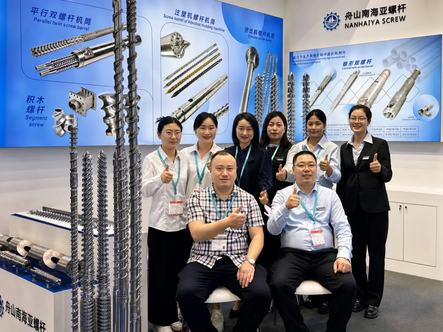
Related Articles
More insights on screw barrel technology and plastics processing.
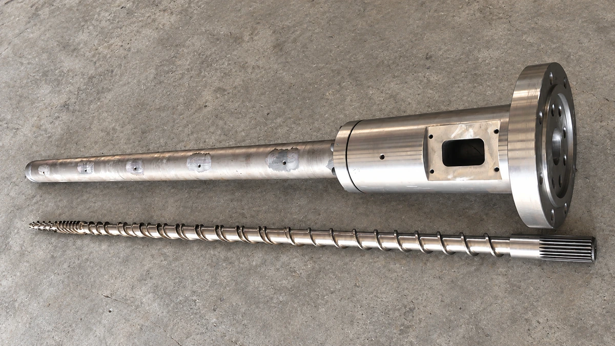
Why Your Single Screw Extruder Design Causes Extrusion Defects
Nov 13, 2026
Learn how single screw extruder design parameters—L/D ratio, compression ratio, channel depth, and mixing elements—affect melt quality, throughput, and defects.
Read Article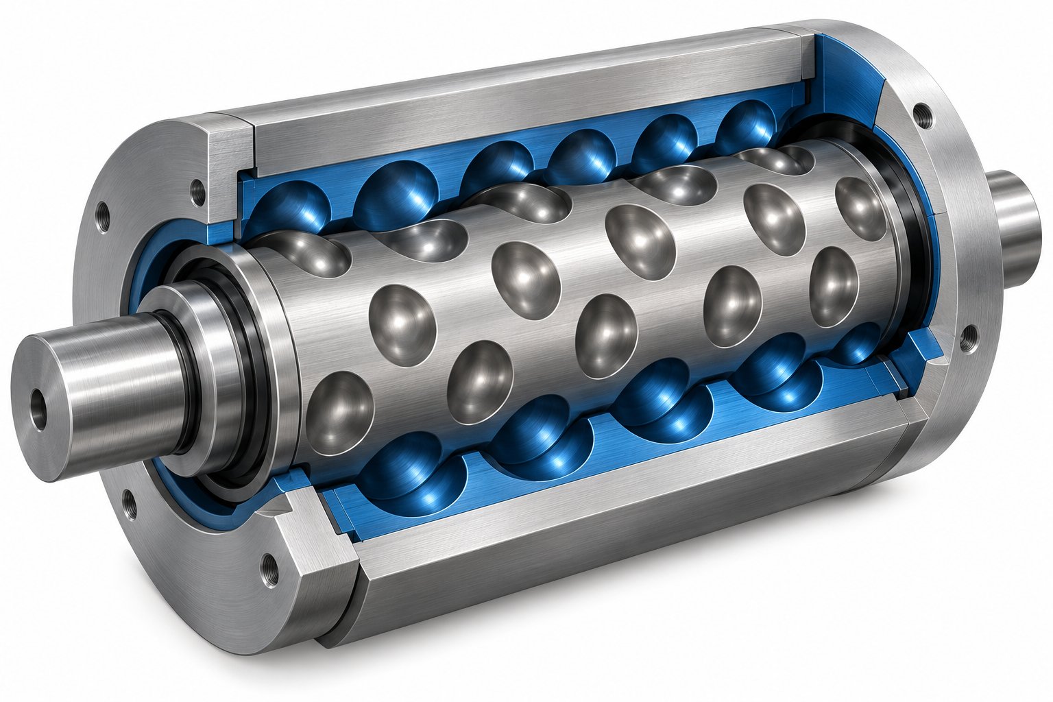
Cavity Transfer Mixer: The Blender Your Extruder Didn't Know It Needed
Nov 13, 2026
Learn how a cavity transfer mixer (CTM) upgrades single-screw extruder mixing. Covers working principles, key parameters, integration, applications, and comparisons.
Read Article
Extruder Barrel Alignment Decoded: Tolerances Most Plants Miss
Nov 13, 2026
Learn extruder barrel alignment tolerances, laser procedures, thermal offsets, and proactive schedules most plants miss — for single-screw and twin-screw lines.
Read ArticleLooking for something else?
Search by material, symptom or product and jump straight to the relevant page.
These are navigation suggestions based on keyword matching — not a quotation, not a delivery commitment, and not a substitute for engineering review. Final specification is confirmed by our engineers against your drawings and processed material.
Need help with screw barrel selection?
Share your machine model, processed material and application. Our team can help with pricing and technical support.