

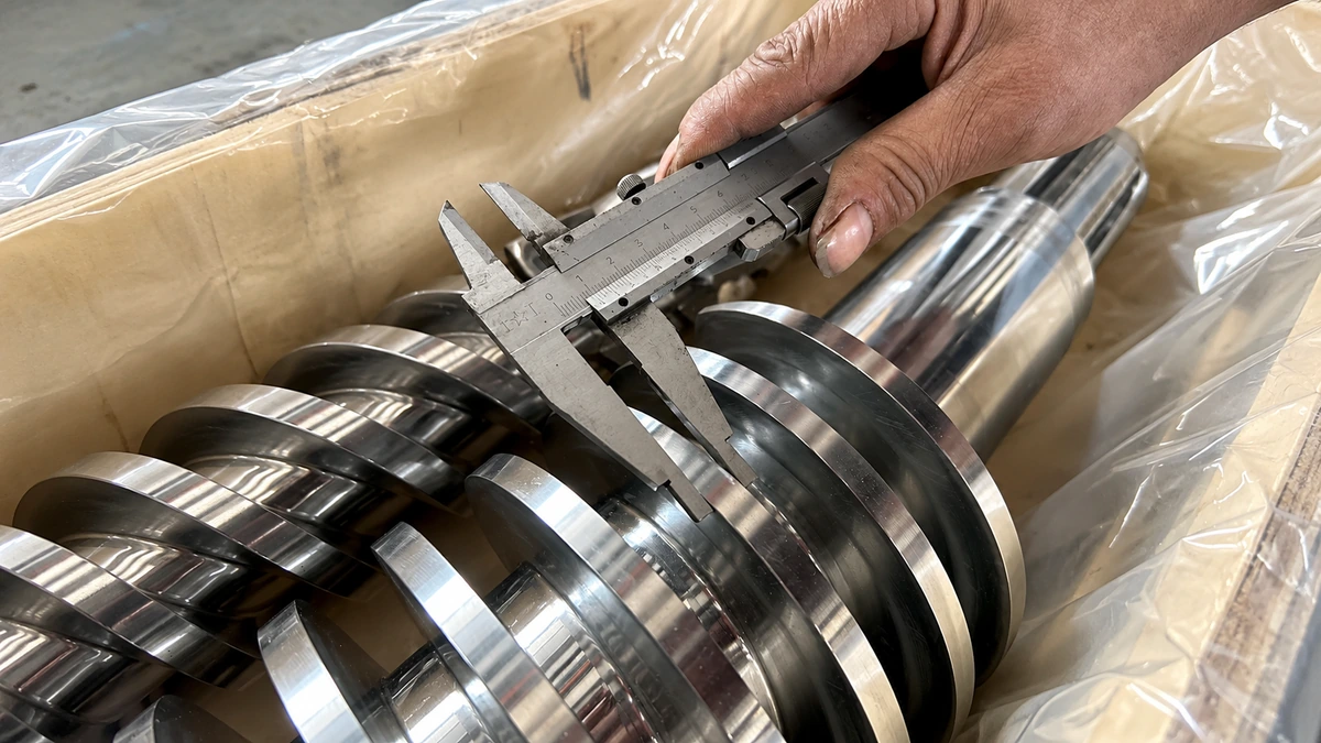
What Feed Screw Design Really Means and Why It Matters
Search for information on feed screw design, and you'll quickly notice a problem. Plastics engineers find extrusion-specific guidance. Bulk material handlers find screw conveyor feeder specs. Packaging teams find timing-screw references. Each industry treats the discipline as its own, yet the underlying engineering challenge is identical: translating what you know about a material, a throughput target, and a machine's physical constraints into precise screw geometry that actually delivers consistent results.
Defining Feed Screw Design Across Industries
Feed screw design is the engineering discipline of determining screw geometry — including diameter, pitch, channel depth, flight configuration, and compression ratio — based on a material's physical properties, a process's throughput requirements, and the mechanical constraints of the equipment, in order to achieve controlled, efficient material conveyance or plasticating performance.
That definition applies whether you're sizing a screw feeder for granular animal feed, specifying a plasticating screw for a single-screw extruder, or engineering a dosing auger for pharmaceutical powders. The feed structure of the screw — its zones, its flight profile, its channel geometry — follows the same foundational principles across all of these contexts. What changes are the material inputs and performance targets, not the design logic itself.
Why Feed Screw Geometry Matters for Process Outcomes
Geometry choices cascade directly into real-world outcomes. In plastics processing, research from Paderborn University demonstrates that even small variations in screw geometry influence melt quality, thermal homogeneity, and maximum achievable throughput. In bulk material handling, a feed screw conveyor study published in the Journal of Physics: Conference Series showed that improper selection and combination of key parameters — blade diameter, pitch, and shaft speed — seriously affect conveying efficiency and performance. In packaging, the wrong pocket profile or pitch progression means inconsistent portion weights and line stoppages.
Imagine two screw feeders with identical diameters running the same product. One delivers stable, predictable output. The other surges, bridges, or overheats. The difference almost always traces back to geometry — channel depths that don't match the material's bulk density, compression rates that ignore how the product compacts, or flight configurations chosen by convention rather than calculation.
This article consolidates those scattered, industry-specific principles into a single resource. You'll find the geometry parameters that govern every screw's behavior, the zone-by-zone design logic behind them, and the material-property considerations that should drive every decision — regardless of whether your screw conveys pellet feed, melts polyethylene, or doses spice blends into pouches.
The starting point for all of it is understanding exactly which geometry parameters you're working with and how each one shapes performance.
Critical Geometry Parameters That Control Performance
Every feed screw — whether it sits inside an extruder barrel, a discharge screw conveyor, or a screw conveyor with hopper — is defined by a handful of measurable geometry parameters. Change any one of them, and you shift throughput, pressure, shear, mixing behavior, or all four simultaneously. The challenge is that most references list these parameters without explaining why they matter or how they interact. That gap leads to geometry choices based on convention rather than engineering reasoning.
Let's break down each parameter, connect it to functional performance, and give you the vocabulary to evaluate any screw specification critically.
L/D Ratio and Compression Ratio Explained
The length-to-diameter ratio (L/D) is the total flighted length of the screw divided by its nominal diameter. A screw with a 60 mm diameter and 1,800 mm of flighted length has an L/D of 30:1. Sounds simple, but this single number dictates how much processing the material undergoes between the feed throat and the discharge point.
Shorter L/D values — think 20:1 or less — suit straightforward conveying tasks or materials that melt easily and don't need extended residence time. Longer ratios, in the range of 24:1 to 34:1 for plasticating applications, give the screw more room to accomplish melting, mixing, venting, and pressure development. PET sheet extrusion, for example, often calls for screws in the 28:1 to 32:1 range because the process requires a dedicated vent zone that can consume several diameters of screw length. Bulk material feedscrews, by contrast, frequently operate at much lower L/D values since their job is conveying, not melting.
Here's the key insight: longer is not automatically better. Extending the L/D increases residence time, energy consumption, wear surface area, and the risk of thermal degradation for heat-sensitive materials. The right L/D matches the process demands — no more, no less.
Compression ratio works hand-in-hand with L/D. It compares the channel volume in the feed zone to the channel volume in the metering zone. A standard 3-zone single screw typically uses compression ratios in the 2:1 to 4:1 range. Lower values — around 2:1 — suit heat-sensitive polymers like PVC, where excessive compression generates damaging shear heat. Higher ratios work for tougher or more crystalline resins, but they also raise melt temperature and torque demand.
Imagine compression ratio as the "squeeze factor." Too little compression, and air stays trapped in the material, causing voids or inconsistent output. Too much, and you're overworking the material — generating excess heat, spiking motor load, and potentially degrading the product before it ever reaches the die.
Channel Depth, Flight Width, and Flight Clearance
Channel depth is arguably the single most impactful dimension on a feed screw. It's the distance from the top of the flight to the screw root, and it directly controls how much material the screw can carry per revolution.
In a typical 3-zone screw, the feed zone has the deepest channels because the goal there is maximum volumetric intake of low-bulk-density solids — pellets, powders, or flakes. As you move into the transition zone, the channel gradually becomes shallower, compacting the material and forcing out trapped air. The metering zone has the shallowest channel, creating a controlled, high-pressure pumping section that delivers uniform output. As NC State Extension's extrusion processing guide notes, channel depth decreases in the order of conveying, compression, and metering zones — and decreasing either channel depth or width increases shear input into the material.
You'll notice that getting the feed zone channel depth wrong has an outsized impact. Too shallow, and the screw starves — it can't pull in enough material to hit the target throughput. Too deep, and the material tumbles without being gripped, reducing conveying efficiency. The "right" depth depends on the feedstock's bulk density and particle characteristics, a relationship we'll explore in detail later in this article.
Flight width, also called land width, is the flat top surface of the flight that nearly contacts the barrel wall. Wider flights increase the sealing effect between the screw channel and the barrel, reducing leakage flow — the backward seepage of material over the flight tip from the high-pressure side to the low-pressure side. However, wider flights also increase the shear area, generating more frictional heat. For heat-sensitive materials, that trade-off matters.
Flight clearance is the radial gap between the flight tip and the barrel bore. Tighter clearances minimize leakage flow and improve pumping efficiency, but they accelerate wear on both the screw flights and the barrel liner. As screws wear, this clearance widens — and that's when operators start noticing output drops, pressure instability, and rising melt temperatures at the same RPM settings. Monitoring flight clearance over time is one of the most practical indicators of when a screw needs refurbishment.
Helix Angle and Its Influence on Conveying Efficiency
The helix angle is the angle between the screw flight and a plane perpendicular to the screw axis. For a standard square-pitch screw — where the pitch equals the diameter — the helix angle works out to approximately 17.66 degrees. Most general-purpose feed screws use this configuration as a starting baseline.
Why does this angle matter? Because it determines the balance between drag flow and pressure flow. Drag flow is the forward movement of material caused by the barrel wall dragging it along the rotating screw channel. Pressure flow is the backward leakage driven by the pressure gradient from metering zone to feed zone. Research published in Polymer Engineering & Science specifically separates screw flow into these two components — rotational flow induced by screw rotation and pressure-driven flow from die backpressure — to accurately model metering zone behavior.
A larger helix angle (steeper flights) increases the axial conveying component but reduces the channel cross-sectional area, lowering volumetric capacity per flight. A smaller helix angle (flatter flights) does the opposite: it increases channel volume but slows forward material transport per revolution. Deviating from the standard square pitch is a deliberate engineering decision — for instance, using a steeper helix near the feed throat of a screw conveyor with hopper to aggressively pull material away from the hopper opening, then transitioning to standard pitch downstream.
The interplay between helix angle, screw speed, and material friction against the barrel wall ultimately determines whether the screw conveys efficiently or simply churns material in place.
Geometry Parameter Reference Summary
The table below consolidates these parameters into a quick-reference format. Use it as a starting checklist when evaluating any screw specification — whether for a new build, a retrofit, or a troubleshooting investigation.
| Geometry Parameter | Typical Range | Primary Performance Impact |
|---|---|---|
| L/D Ratio | 20:1 (conveying) to 34:1 (plasticating/vented) | Residence time, melting capacity, mixing opportunity, and devolatilization capability |
| Compression Ratio | 2:1 (heat-sensitive) to 4:1 (crystalline/tough resins) | Material compaction, air removal, shear heat generation, and torque demand |
| Feed Zone Channel Depth | Deep relative to metering zone (material-dependent) | Solids intake capacity, volumetric throughput, and feed consistency |
| Metering Zone Channel Depth | Shallow, constant depth (material-dependent) | Pumping pressure, melt homogeneity, and output stability |
| Flight Width (Land Width) | Approximately 10% of screw diameter (general guideline) | Leakage flow control, shear heat generation, and sealing effectiveness |
| Flight Clearance | Tight tolerance per barrel diameter (wear-dependent) | Pumping efficiency, wear rate, and pressure stability over service life |
| Helix Angle | ~17.66° at square pitch (pitch = diameter) | Drag flow versus pressure flow balance, conveying rate, and channel volume |
Each of these parameters exists on its own, but none of them operates in isolation. A deep feed channel paired with an aggressive compression ratio creates a very different processing environment than the same channel paired with a gentle taper. The geometry parameters define what each zone of the screw can accomplish — and understanding how those zones work together is where feed screw design moves from a list of numbers to a coherent engineering strategy.
Understanding Feed Screw Zones and Their Functions
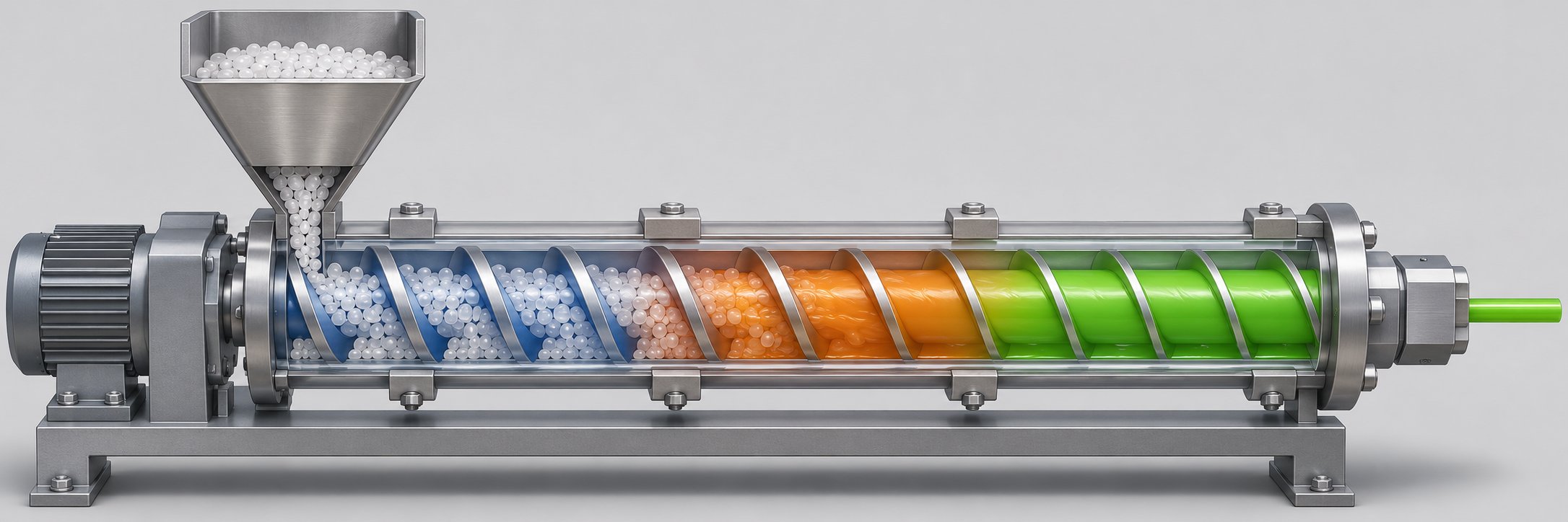
A list of geometry parameters tells you what a screw looks like. Zone design tells you why it looks that way. Every dimension along the screw's length serves a specific processing purpose, and those purposes change as material moves from the hopper toward the discharge. Most references name these zones — feed, transition, metering — without explaining the engineering logic that shapes each one. That gap leads to feed screws built from generic templates rather than deliberate, zone-by-zone reasoning.
Here's the sequential flow from hopper to die, with the design intent behind each stage:
- Feed zone — solids intake and initial conveying
- Transition (compression) zone — compaction, air removal, and early plasticating
- Metering zone — pressure development and uniform output delivery
- Mixing section(s) — homogenization of melt, color, or additives (when required)
Feed Zone Design for Consistent Solids Conveying
The feed zone has one job: pull material in and push it forward as fast and as consistently as possible. Deep channels maximize the volumetric intake of low-bulk-density solids — pellets, flakes, powders, or granules. But channel depth alone doesn't guarantee good screw feeding. What really drives solids conveying is the friction differential between the barrel wall and the screw root.
Imagine a pellet sitting in the screw channel. If the barrel surface grips it harder than the screw surface does, the pellet gets dragged forward along the barrel as the screw rotates beneath it. If the screw root is too "sticky," the pellet just spins with the screw and goes nowhere. This is why polished screw roots and rougher barrel bores are standard practice — the friction imbalance is intentional.
Grooved feed sections take this principle further. By machining axial or helical grooves into the barrel wall at the feed zone, engineers dramatically increase the barrel-side friction. Research from the University of Stuttgart found that grooved feed zones fundamentally change how pressure builds in the system. In smooth-barrel extruders, pressure accumulates gradually along the entire screw length. In grooved-barrel extruders, the significant pressure buildup already occurs in the feed zone, making the downstream melting and metering zones act as pressure consumers rather than pressure builders. The result is a throughput that becomes largely independent of die backpressure — a major advantage for process stability.
That same research demonstrated how granule geometry interacts with feed zone design. Small, spherical particles maintained linear throughput scaling up to 1,200 rpm in a smooth barrel, while larger lenticular and cylindrical granules began showing non-linear throughput drop-off at roughly 300 rpm. The takeaway? Feed zone design can't be separated from the physical characteristics of what you're feeding into it, whether you're running a horizontal extruder or a vertical screw feeder pulling product from an overhead hopper.
Transition Zone Geometry and Gradual Compression
Once material clears the feed zone, it enters the transition — or compression — zone. Here, channel depth progressively decreases along the screw's length, compacting the loosely packed solid bed into a denser mass. In extrusion contexts, this is also where plasticating begins: the combination of compressive force, barrel heat, and inter-particle friction starts converting solid pellets into a melt.
The critical design variable in this zone is the taper rate — how quickly the channel depth decreases per unit of screw length. Get this wrong, and the consequences cascade in both directions. Too aggressive a taper compresses material faster than it can melt or densify, generating excessive torque, pressure spikes, and potential screw deflection. Too gradual a taper fails to compact adequately, leaving trapped air pockets that show up as voids, surface defects, or output surging downstream.
The taper rate must match the material's bulk-density-to-melt-density change. A highly crystalline polymer like HDPE undergoes a substantial density increase as it transitions from solid pellets to melt, demanding a higher compression ratio and a corresponding taper. An amorphous resin like polystyrene changes density less dramatically, so its transition zone can be shorter and less aggressive. For bulk material applications — where there's no melting — the compression zone still matters because it removes interstitial air and ensures the material feeds forward as a coherent plug rather than a loosely tumbling mass.
A standard general-purpose screw uses a single, linear taper. Barrier screw designs split this zone into two channels separated by a secondary flight, directing unmelted solids along one path and melt along another. This prevents the solids bed from breaking up prematurely — a phenomenon that, in standard screws, scatters unmelted material throughout the melt channel and severely reduces melting efficiency.
Metering Zone for Pressure and Flow Uniformity
The metering zone is where consistency is either made or lost. Its channel depth is shallow and constant — no taper, no compression, just a uniform pumping channel designed to build stable pressure and deliver homogeneous output to the die or discharge point.
Think of it as the quality-control section of the screw. The feed zone determines how much material enters the system. The transition zone determines how well that material compacts or melts. The metering zone determines how uniformly it exits. A metering zone that's too short can't develop enough pressure for consistent die flow, leading to output pulsation. One that's too long adds unnecessary residence time and shear, raising melt temperature and risking thermal degradation in heat-sensitive materials.
For feed screws operating in non-plasticating applications — conveying powders, granules, or bulk solids — the metering zone equivalent serves the same function: it creates a stable, pressurized plug of material at the discharge end, ensuring that the volumetric or gravimetric output remains steady cycle to cycle.
Mixing Sections and Their Placement
Not every screw needs a dedicated mixing section, but many processes can't achieve acceptable results without one. Mixing sections address two distinct problems — and the solution for each looks very different.
Dispersive mixing breaks down agglomerates, gels, or unmelted particles by forcing material through tight clearances at high shear stress. The Maddock mixer is a widely recognized example: melt passes over a narrow clearance gap where it experiences high shear, effectively functioning as a dam that prevents unmelted polymer from passing downstream. This also contributes to melting capacity, since the energy input helps finish off any remaining solids.
Distributive mixing reorients and recombines melt streams to achieve spatial uniformity — essential for even color dispersion or additive distribution. The Saxton mixer divides melt many times across its multi-flighted geometry and recombines it through numerous reorientations, providing strong distributive action with relatively low shear input. Hybrid designs like the Egan mixer combine undercut flights with multiple high-shear zones, delivering significant levels of both dispersive and distributive mixing simultaneously.
Cavity transfer mixers represent yet another approach, using opposing hemispherical cavities in the screw and barrel to repeatedly split and recombine the melt stream. Each of these mixing technologies addresses a different balance of shear intensity, pressure drop, residence time, and thermal impact.
Placement matters as much as mixer type. Mixing sections are typically positioned after the metering zone — or integrated at the end of the transition zone — to ensure the material is fully melted before it encounters the mixer's geometry. Installing a dispersive mixer too early, before solids are adequately compacted, can jam unmelted particles against the restrictive clearances and spike screw torque.
The important caution here: mixing sections are specialized design elements evaluated against specific process requirements, not universal upgrades that improve every screw. Adding a Maddock section to a screw that already melts well but has a color-distribution problem won't fix the root cause — that situation calls for distributive mixing instead. Matching the mixer to the actual deficiency is what separates effective screw engineering from trial-and-error modifications.
Each zone's geometry is purposeful, but that purpose only holds when the flight configuration — pitch, flight type, and progression — is chosen to suit the material being processed. A standard full-pitch flight isn't always the right answer, and in many applications, it's the wrong one entirely.
Flight Types and Pitch Strategies for Uniform Material Flow
Selecting the right zone lengths and channel depths is only half the geometry equation. The flight configuration — its pitch, its profile, and any modifications to its outer edge — determines how material actually behaves inside the screw channel. Two screws with identical diameters, L/D ratios, and compression ratios can deliver radically different output consistency if one uses a standard full-pitch flight while the other uses a variable-pitch or ribbon design. Yet most engineering references treat flight selection as an afterthought, listing types without explaining when or why each one is appropriate.
Here's a practical breakdown of the major flight types, the pitch strategies behind them, and the trade-offs that should guide your decision.
Full Pitch, Short Pitch, and Variable Pitch Flights
The baseline for nearly every feed screw is the standard (full) pitch configuration, where the pitch — the axial distance between adjacent flight crests — equals the screw diameter. This square-pitch geometry delivers a balanced relationship between conveying rate and channel volume, making it the default choice for horizontal conveying of free-flowing materials and inclines up to roughly 10 degrees. If you're starting a screw feed system design from scratch and the material flows easily, standard pitch is almost always the starting point.
Short pitch flights reduce that axial spacing, typically to two-thirds of the screw diameter for a standard short-pitch design, or to one-half of the diameter for a half-pitch configuration. Why shorten the pitch? Imagine an inclined or vertical screw. Gravity constantly tries to pull material back down the channel. With a shorter pitch, each flight acts as a smaller "step," reducing the distance material can slide backward per revolution. That's why short-pitch flights are standard in inclined screw conveyors operating above 10 degrees and in vertical screw feeders, where preventing material rollback is the primary design challenge. They're also common at the inlet end of variable-pitch screw feeder assemblies, providing tight initial control before the pitch opens up downstream.
Variable pitch designs progressively increase the pitch from the inlet to the discharge end. This is one of the most effective — and most underutilized — strategies for achieving uniform material withdrawal from hoppers, bins, and silos. Here's the problem it solves: when a constant-pitch screw sits beneath a hopper opening, the flights closest to the back wall of the hopper tend to do most of the work. Material preferentially fills those flights because they're fully exposed to the hopper's static head of material. The flights at the front of the hopper opening carry less material, creating an uneven draw-down pattern that promotes bridging, rat-holing, and inconsistent feed rates.
By starting with a tighter pitch under the hopper and gradually widening it toward the discharge, each successive flight gains slightly more volumetric capacity. The result is a more even withdrawal across the entire hopper opening, pulling material uniformly rather than preferentially from one side. Mass flow screw designs take this concept further by combining variable pitch with an internal cone, creating increasing volume with every flight to ensure uniform withdrawal even from large-diameter storage vessels.
Tapered-pitch strategies share a similar goal but approach it differently. Instead of varying the axial pitch along the screw length, tapered flight designs use a constant pitch with a gradually widening flight outer diameter — typically increasing from half to full diameter. This produces the same effect of progressively increasing volumetric capacity per flight, and it's a favored approach in live-bottom screw feeders and multi-screw extraction systems where several parallel screws must draw material down evenly across a wide bin floor. The tapered geometry prevents the material closest to the screw inlet from being disproportionately extracted, which would otherwise create dead zones and compaction problems in the hopper above.
Cut Flights, Ribbon Flights, and Paddle Configurations
Standard, short, and variable pitch flights all assume the material needs to be conveyed — moved from point A to point B with minimal disruption. But what if conveying isn't the only goal? Many screw feed system applications require mixing, agitation, or deliberate disruption of the material flow. That's where modified flight profiles come in.
Cut (notched) flights feature regularly spaced notches along the outer edge of each flight. These notches allow a portion of the material to cascade backward through the gaps, creating a tumbling, folding action that promotes mixing and breaks up cohesive clumps. Cut flight conveyors are frequently specified for materials prone to sticking or packing — hydrated lime, dried milk, talc, or pharmaceutical powders. The trade-off is straightforward: every notch that improves mixing is a notch that reduces net forward conveying efficiency. You'll move less material per revolution compared to a full-flight screw of the same pitch and diameter. Cut and folded flights take this a step further by bending the notched sections into small lifting paddles, creating even more aggressive agitation and aeration — useful when you need homogeneous temperature distribution during heating, cooling, or chemical conditioning.
Ribbon (hollow) flights solve a different problem entirely. Picture a feed screw processing a thick, sticky material — wet sludge, adhesive compounds, or dough-like mixtures. In a conventional solid-core screw, that material wraps around the shaft and builds up in the center of the channel, eventually choking flow. Ribbon flights eliminate this center-core buildup by maintaining an open gap between the inner edge of the flight and the central pipe. The material can pass through and around the shaft rather than accumulating against it. Double ribbon flight configurations add a second set of flights offset 180 degrees, creating a countercurrent mixing action that further prevents dead zones in sticky or viscous products. The compromise? Ribbon flights inherently carry less material per revolution than solid flights because part of the channel volume is occupied by the open ribbon structure rather than by product.
Paddle configurations prioritize gentle blending over conveying force. Adjustable paddles mounted between screw flights — or arranged in a helix directly around the shaft — redirect and fold the material without the aggressive shear of cut flights. With up to four paddles per pitch, you can fine-tune the intensity of mixing. Single-flight screws with interspersed paddles offer a balance: the flights maintain reasonable forward transport while the paddles provide controlled agitation. Full paddle screws (no continuous flights at all) deliver the most aggressive mixing and controlled flow but sacrifice most of their conveying capability, making them suitable for blending stations rather than transport lines.
Pocket Profiles and Specialized Geometries
Beyond the standard screw conveyor types described above, certain niche applications demand entirely custom flight geometries. Pocket-profile feed screws, for example, are engineered for packaging timing applications where individual product units — bottles, caps, containers — must be spaced at precise intervals along a production line. Each "pocket" in the screw's profile cradles a single product, and the pitch progression controls the spacing as items move from a random infeed to an evenly timed discharge. The geometry here isn't about bulk conveying efficiency at all; it's about positional accuracy and gentle product handling at high line speeds.
Other specialized geometries include conical screws for bin dischargers, where the increasing diameter from top to bottom ensures that material is extracted across the full cross-section of a storage vessel, and double-flight screws that add a second set of flights offset by 180 degrees for smoother, surge-free discharge in high-capacity applications.
Flight Type Comparison
The table below maps each major flight type to the material characteristics and application contexts where it performs best. Use it as a selection starting point — but always validate against the specific material properties of your process, a topic the next section covers in depth.
| Flight Type | Best-Suited Material Characteristics | Typical Application Context | Key Trade-Off |
|---|---|---|---|
| Standard (Full) Pitch | Free-flowing granules, pellets, dry powders | Horizontal conveying, general-purpose extrusion | Versatile baseline; limited mixing capability |
| Short Pitch (2/3 or 1/2 diameter) | Free-flowing to moderately cohesive dry solids | Inclined and vertical screw conveyors, steep-angle feeders | Prevents rollback; reduces throughput per revolution |
| Variable Pitch | Free-flowing bulk solids requiring metered withdrawal | Screw feeders under hoppers, bins, and silos | Uniform draw-down; requires precise pitch progression sizing |
| Tapered Flight | Lumpy, heterogeneous, or bridge-prone materials | Live-bottom feeders, multi-screw extraction, bin dischargers | Even intake across wide openings; more complex fabrication |
| Cut (Notched) Flight | Cohesive, sticky, or compaction-prone powders | Mixing, agitation, aeration in processing lines | Improved mixing; reduced net conveying efficiency |
| Cut and Folded Flight | Lightweight, heat-sensitive, or cohesive powders | Heating, cooling, chemical conditioning applications | Aggressive mixing and aeration; significant conveying loss |
| Ribbon (Hollow) Flight | Viscous, sticky, caking, or high-moisture materials | Sludge handling, food processing, adhesive transport | Prevents center-core buildup; lower volumetric throughput |
| Paddle | Materials requiring gentle blending or controlled agitation | Feed mixing, de-agglomeration, specialty chemical blending | Excellent mixing control; minimal forward conveying force |
| Pocket Profile | Discrete product units (bottles, caps, containers) | Packaging line timing and spacing applications | Precise positional control; not suitable for bulk flow |
| Mass Flow (Cone + Variable Pitch) | Powders, granules, and bulk solids prone to rat-holing | Silo and bin discharge feeders requiring uniform withdrawal | Best uniformity from large vessels; higher design complexity |
You'll notice a pattern in that table: every flight modification that improves one performance attribute — mixing, anti-bridging, rollback prevention — costs something in another attribute, usually conveying rate or fabrication simplicity. There's no universally "best" flight type, only the one that best matches your material and your process goals. And that match depends entirely on understanding the physical properties of the material itself — its bulk density, its cohesion, its friction behavior, and how those characteristics change under the conditions inside your screw.

How Material Properties Shape Every Design Decision
Every geometry parameter discussed so far — channel depth, compression ratio, pitch strategy, flight type — exists to handle a specific material behavior. Yet most feed screw design projects start with the machine, not the material. Engineers pick a diameter, default to a standard pitch, and hope the product cooperates. When it doesn't, the troubleshooting begins. Flipping that sequence — starting with a thorough material characterization and letting the data drive geometry — eliminates the majority of screw performance problems before a single flight is cut.
As BulkInside's coverage of tailored screw conveyor engineering emphasizes, detailed analysis of the material to be handled is the one phase that must not be overlooked — without it, even the best screw geometry can fall short, leading to frequent breakdowns and high maintenance costs. Here's how the most critical material properties map directly to the geometry decisions you'll face.
Bulk Density, Particle Size, and Flow Characteristics
Bulk density is the bridge between what your production schedule demands in kilograms per hour and what the screw must deliver in cubic centimeters per revolution. A light, aerated powder at 350 kg/m³ requires roughly three times the volumetric channel capacity of a dense mineral granule at 1,100 kg/m³ to hit the same mass throughput. Get the bulk density wrong — or use a single catalogue value without accounting for the difference between loose and compacted states — and the feedscrews you specify will either starve or overload.
Particle size and size distribution compound the problem. A narrow, uniform pellet blend flows predictably into the screw channel, filling the available volume with reasonable consistency. A wide distribution — fines mixed with coarse granules — behaves differently. The fines sift through gaps between larger particles, potentially segregating during storage and creating uneven feed composition. Oversize lumps can wedge between the flight tip and the barrel or trough wall, causing jams. Convello's screw conveyor selection guide makes the point clearly: "the maximum particle or lump — not the average particle — can set the minimum screw diameter and inlet clearance." Your auger feed screw geometry needs to accommodate the worst-case particle, not the typical one.
Flow characteristics — angle of repose, cohesion, and wall friction — dictate how material interacts with the hopper-to-screw interface. Free-flowing granules with a low angle of repose fill the feed zone predictably. Cohesive powders with high internal friction can bridge above the inlet, forming stable arches that starve the screw regardless of how well the downstream geometry is designed. Wall friction determines whether material slides freely along the trough or barrel surface or smears and builds up, progressively reducing effective channel volume.
These flow properties also determine whether the screw operates in a flood-fed or starve-fed condition — and that distinction reshapes the entire design approach. A flood-fed screw feeder sitting beneath a full hopper must manage the static head of material pressing down on the inlet flights. Variable pitch, tapered diameter, or mass-flow inlet geometry may be required to prevent compaction and ensure even withdrawal. A starve-fed screw — one where an upstream metering device controls the feed rate — doesn't face inlet compaction, but its feed zone must still be deep enough to capture and convey whatever arrives without spillback.
Moisture, Abrasiveness, and Coefficient of Friction
Moisture content changes almost everything about how a material behaves inside screw feed systems. A dry powder that flows freely at 2% moisture can become a sticky, bridging nightmare at 6%. Moisture increases inter-particle cohesion, promotes caking during shutdowns, and alters the friction coefficient against both the barrel wall and the screw root. In extreme cases, wet material packs so tightly that screw torque spikes on restart, overloading the drive or shearing coupling pins.
Abrasiveness determines how long the screw lasts, not just how well it works on day one. Silica sand, glass-filled polymers, calcium carbonate, and mineral fillers all erode flight edges, widen clearances, and progressively degrade pumping efficiency. A screw designed without accounting for abrasive wear will hit its performance targets initially — then steadily deteriorate as flight tips wear back and the effective clearance between flight and barrel doubles or triples. The geometry itself is temporary unless the material-of-construction and surface treatments are matched to the feedstock's abrasive character.
Perhaps the most overlooked material property in feed screw design is the differential friction coefficient — the difference between the material's friction against the barrel wall and its friction against the screw root. Solids conveying in the feed zone depends entirely on this imbalance. High barrel-side friction and low screw-side friction push material forward efficiently. If both surfaces have similar friction values, the material simply rotates with the screw without advancing, and throughput collapses. This is why surface finish specifications for the screw root and barrel bore are engineering decisions, not cosmetic ones. A polished screw root paired with a rougher or grooved barrel bore deliberately engineers the friction differential that makes conveying work.
Melt Behavior and Polymer-Specific Considerations
For extrusion and injection molding applications, material characterization extends beyond the solid state into melt behavior. Every thermoplastic has a processing window defined by its melt temperature range, viscosity curve, and thermal degradation threshold — and these boundaries directly constrain the geometry choices available to the screw designer.
A heat-sensitive resin like PVC has a narrow window between the temperature required for adequate melt flow and the temperature at which the polymer begins to degrade. That forces the use of low compression ratios (often around 2:1), shallow metering channels, and shorter transition zones — geometry that minimizes shear-generated heat. An aggressive taper or a high-shear mixing section that works perfectly for polyethylene would destroy PVC within seconds. At the other end of the spectrum, highly crystalline polymers like HDPE or nylon require more energy input to melt their ordered molecular structures, calling for deeper feed zones, higher compression ratios, and often longer L/D ratios to provide the residence time and mechanical energy needed for complete plasticating.
Viscosity curves add another layer. A polymer with a steep viscosity-temperature relationship changes flow behavior rapidly with small temperature shifts, making the metering zone particularly sensitive to thermal uniformity. As Addcomposites' extrusion fundamentals guide notes, shear heating can account for 60-80% of the total heat input in many extrusion setups. That means the screw geometry itself — through channel depth, flight clearance, and compression rate — is the primary heating mechanism, not the barrel heaters. If the geometry generates too much shear for a thermally sensitive polymer, barrel cooling can't always compensate fast enough to prevent degradation.
Thermal degradation windows also influence zone lengths. A material that degrades after 4 minutes at processing temperature imposes a hard limit on residence time, which in turn limits the maximum L/D ratio and the length of any mixing sections. Extending the screw for better mixing is pointless if the additional time pushes the polymer past its degradation threshold.
Material Property Checklist for Feed Screw Design
Before beginning any screw geometry project — whether it's a new build, a retrofit, or a troubleshooting investigation — document these material properties. Missing even one can lead to a geometry mismatch that no amount of downstream adjustment can fix.
- Bulk density — both loose and compacted values at operating moisture content
- Particle size distribution — including maximum lump or pellet dimension
- Particle shape — spherical, lenticular, cylindrical, flake, or irregular
- Angle of repose — indicator of flowability and hopper interface behavior
- Cohesion and internal friction angle — predicts bridging and rat-holing risk
- Wall friction coefficient — against both the barrel/trough surface and the screw root surface
- Moisture content — normal operating range and worst-case maximum
- Abrasiveness — wear index, hardite scale, or qualitative rating from prior experience
- Temperature sensitivity — maximum allowable product temperature and degradation onset
- Melt temperature and range — for plasticating applications, the full processing window
- Viscosity versus temperature and shear rate — rheological data for extrusion or injection molding
- Corrosiveness — chemical compatibility with candidate screw and barrel materials
- Friability or fragility — whether the material breaks, chips, or degrades under mechanical stress
- Stickiness and adhesion tendency — buildup risk on screw and housing surfaces
- Hygroscopic behavior — moisture absorption from ambient air during storage and processing
That checklist applies whether you're designing a single-screw extruder for polyethylene film, an auger feed screw for cement powder, or a dosing feeder for pharmaceutical granules. The specific values change with every application, but the questions remain the same — and the answers are what transform a generic screw into one that's genuinely engineered for its job.
Material properties dictate what the screw geometry must accomplish. The construction of the screw — its base metal, its surface hardness, its coatings — determines how long that geometry survives the conditions the material imposes on it.
Screw Construction Materials and Surface Treatments
A perfectly calculated geometry means nothing if the screw can't survive its operating environment. The material being processed doesn't just flow through the screw channel — it grinds against flight tips, reacts chemically with metal surfaces, and imposes torsional loads that test the structural limits of the shaft. Choosing the wrong base metal or skipping a critical surface treatment turns a well-designed feedscrew into a consumable part with an expiration date far shorter than it should be.
Yet material-of-construction selection rarely receives the same engineering attention as channel depth or compression ratio. Too often, the default choice is "whatever we ordered last time." That approach works until you change resins, add a glass-fiber filler, or push throughput higher — and suddenly the screw that lasted three years is worn out in eight months.
Base Metal Options and Their Performance Trade-Offs
The foundation of any feed screw conveyor or plasticating screw is its base metal. This isn't a cosmetic decision — it determines torsional strength, machinability, weldability, and the baseline hardness that everything else builds on.
AISI 4140 is the workhorse of the industry. As Davis-Standard's feedscrew construction guide notes, this chrome-alloy steel offers good machinability and predictable behavior during manufacturing. It can be flame hardened for a minimum level of wear resistance, and a wide range of wear-resistant alloys can be applied to its surface via plasma transferred arc (PTA) welding. For most general-purpose extrusion and screw feed applications processing non-abrasive, non-corrosive polymers, 4140 delivers a practical balance of performance and cost.
AISI 4340 steps up when torsional strength becomes the limiting factor. Its yield strength runs roughly 10 percent higher than 4140, making it the go-to choice for small-diameter screws — where the reduced cross-section concentrates torsional stress — and for large screws with very deep channel depths that amplify bending loads. It shares similar machining and welding characteristics with 4140, so wear-resistant alloys can still be applied.
Nitralloy 135M is widely used across European and Asian markets. The entire screw geometry is case-hardened after machining through a specialized nitriding treatment, producing a uniformly hard surface. The catch? Nitralloy is not recommended for applications requiring welding, which means wear-resistant flight-tip alloys can't be applied. If your process demands hard-faced flights for abrasive materials, Nitralloy may not be the right starting point.
Corrosion-resistant alloys enter the picture when the processed material chemically attacks the screw surface. Precipitation-hardened stainless steels like 15-5 PH and 17-4 PH provide corrosion protection comparable to 304-type stainless while maintaining good mechanical properties. For aggressive environments — fluoropolymer processing, resins releasing hydrochloric or hydrofluoric acid byproducts — higher-grade nickel-chromium alloys such as Inconel, Hastelloy C276, and Duranickel become necessary. These specialty alloys are expensive, and they sacrifice torsional strength for chemical resistance. That trade-off means the screw designer must verify that the shaft can still handle the torque demands of the application after stepping down to a corrosion-resistant base metal.
Tool steels and powder metallurgy grades — CPM 9V, CPM 10V, and similar PM-HIP alloys — offer the highest wear resistance available in a base material. They're exceptionally hard and resist abrasive erosion far better than standard alloy steels. The downside is that they're very difficult to machine, challenging to keep straight during manufacturing, and essentially impossible to weld. That's why these materials are typically limited to smaller-diameter and shorter-length screws where the fabrication challenges are manageable. For larger-diameter feedscrew applications facing severe abrasive wear, encapsulation techniques using complex metal alloys applied via HVOF or D-Gun processes provide an alternative path to surface protection without requiring the entire screw to be made from tool steel.
For non-metallic applications — low-load conveying of food products, pharmaceuticals, or chemically sensitive powders — UHMW polyethylene and acetal (Delrin) screws offer a fundamentally different approach. These polymer-based screws eliminate metal contamination risk, resist chemical attack from most acids and alkalis, and run at low friction without lubrication. They won't handle the torsional loads or temperatures of plasticating applications, but for light-duty screw feed systems in sanitary environments, they're often the smartest choice.
Surface Treatments and Coatings for Extended Life
Base metal selection sets the floor for screw performance. Surface treatments raise the ceiling — sometimes dramatically. The right coating can multiply a screw's service life by an order of magnitude in harsh environments, while the wrong one wastes money or, worse, flakes off into the product stream.
Nitriding is the most common surface hardening treatment for feedscrew applications. The process diffuses nitrogen into the steel surface at elevated temperatures, creating a hard case without significantly altering the screw's dimensions. It's effective against moderate adhesive and abrasive wear, and it's compatible with most standard alloy steels (4140, 4340). However, the hardened case is relatively thin — typically 0.2 to 0.5 mm — so once the nitrided layer wears through, the softer base metal underneath erodes quickly. Nitriding works best as a cost-effective first line of defense for non-extreme applications.
Chrome plating has been a standard screw-root treatment for decades, providing a smooth, low-friction surface that improves material release and resists corrosion. It's particularly useful for preventing material buildup on the screw root in sticky or high-moisture applications. However, hard chrome plating has well-documented limitations. As industrial coating research from Hardide details, the electrolytic deposition process inherently produces micro-cracks in the chrome layer, allowing corrosive agents to reach the substrate beneath. For mildly corrosive environments, chrome still performs adequately. For chemically aggressive processing — PVC, fluoropolymers, flame-retardant compounds — those micro-cracks become pathways for accelerated substrate attack.
Tungsten carbide hard-facing is the heavy-duty answer for abrasive wear on flight tips. Alloys like Colmonoy 56, Colmonoy 83, and Stellite 6 are welded as inlay strips along the flight OD, creating a wear surface far harder than the base metal beneath it. This is the standard approach for processing glass-filled resins, mineral-filled compounds, and any feedstock containing hard particulates that would otherwise erode flight edges within weeks. The selection among these alloys depends on whether your primary wear mechanism is abrasive (hard particles cutting the surface), adhesive (metal-to-metal contact between flight tip and barrel), or a combination of both.
CVD (Chemical Vapor Deposition) coatings represent the newer end of the surface treatment spectrum. Unlike chrome plating, CVD produces a pore-free, homogeneous coating with no micro-cracks, delivering up to 24 times the wear resistance of hard chrome in some abrasive environments. CVD coatings can also be applied uniformly to complex geometries — including internal channel surfaces — that are difficult to coat evenly with electrolytic processes. The trade-off is cost: CVD treatments carry a higher price point than nitriding or chrome, so they're typically reserved for high-value screws in severe service conditions where extended replacement intervals justify the investment.
PVD (Physical Vapor Deposition) coatings — titanium nitride, chromium nitride, and similar thin-film treatments — offer high surface hardness with minimal dimensional change. They're effective against adhesive wear and provide good chemical resistance, making them suitable for screws processing corrosive materials at moderate abrasion levels. Like CVD, PVD coatings add cost, so they're a targeted solution rather than a default specification.
The key principle across all of these treatments: surface treatment selection ties directly back to the material being processed. An abrasive glass-filled nylon demands hard-faced flight tips and possibly a carbide-coated root. A corrosive fluoropolymer needs a nickel-alloy base metal with a pore-free coating. A food-grade starch powder might need nothing more than a polished stainless surface. Matching the coating to the wear mechanism — not just applying the most expensive option available — is what delivers actual return on investment.
Matching Construction to Application Requirements
With this many options on the table, systematic selection matters. The table below maps common construction materials and treatments to their performance characteristics and best-fit applications. Use it as a starting framework, not a final specification — because real-world applications often combine multiple wear mechanisms that require nuanced trade-offs between hardness, corrosion resistance, torsional strength, and cost.
| Construction Material / Treatment | Typical Hardness | Corrosion Resistance | Best-Fit Application |
|---|---|---|---|
| AISI 4140 (flame hardened) | Rc 28–32 base; Rc 53–58 flame-hardened flights | Low | General-purpose extrusion of non-corrosive, non-abrasive polymers |
| AISI 4340 | Rc 32–37 | Low | Small-diameter screws and deep-channel designs requiring high torsional strength |
| Nitralloy 135M (nitrided) | Rc 60–70 case hardness | Low | General-purpose with uniform surface hardness; no welded flight treatments |
| 15-5 PH / 17-4 PH Stainless | Rc 28–40 (age-hardened) | Moderate (comparable to 304 SS) | Moderately corrosive compounds, food-contact applications |
| Inconel 625 / 718 | Rc 25–40 | High | Fluoropolymers, high-temperature resins, aggressive acid byproducts |
| Hastelloy C276 | Rc 20–30 | Very High | Highly corrosive environments including HCl and HF exposure |
| CPM 9V / 10V (tool steel) | Rc 53–62 | Low | Severely abrasive feedstocks; smaller-diameter screws only |
| Stellite 6 / Colmonoy 83 (flight inlay) | Rc 40–62 | Moderate to High | Flight-tip hard-facing for glass-filled, mineral-filled, or abrasive compounds |
| Hard Chrome Plating (root) | Rc 68–72 | Moderate (micro-crack limitation) | Root surface protection for sticky or mildly corrosive materials |
| CVD Tungsten Carbide Coating | HV 1200–1600+ | High (pore-free) | Severe abrasion and corrosion in high-value, extended-service screws |
| UHMW / Acetal (non-metallic) | Shore D 60–70 | High (chemical inertness) | Low-load food, pharmaceutical, and chemical powder conveying |
Notice the recurring theme: every material and coating choice involves a trade-off. The highest-hardness options sacrifice torsional strength or weldability. The most corrosion-resistant alloys cost significantly more and may not handle the torque demands of high-output processing. Chrome provides an excellent surface finish but harbors micro-cracks that limit its chemical resistance. No single row in that table is universally "best" — only best for a particular combination of feedstock, processing conditions, and economic constraints.
This is precisely where the selection process benefits from structured engineering review rather than catalogue-based guesswork. When evaluating screw materials and surface treatments for a specific polymer or bulk material, working with engineers who assess these variables against real processing demands helps ensure the metallurgy matches the application before committing to manufacturing. Services like NANHAIYA's custom screw design evaluation, for example, review material-of-construction options alongside flight geometry, compression ratios, and mixing sections — treating construction as an integrated design decision rather than an afterthought.
Getting the construction right protects the geometry you've engineered. But geometry and construction only deliver results when they're matched to the specific demands of the industry and application type — and those demands vary far more than most general references acknowledge.

Feed Screw Applications Across Industries
A plastics engineer designing a barrier-flighted extruder screw and a bulk-material specialist sizing a hopper screw conveyor for cement powder rarely read the same references. A packaging engineer selecting a timing screwfeeder for a bottling line inhabits yet another information silo. The result? Each industry reinvents principles the others already solved — and cross-pollination of ideas that could improve all three happens far too slowly.
The geometry parameters, zone logic, and material-property relationships covered in earlier sections apply universally. What changes from one industry to the next is which parameters take priority and which trade-offs are acceptable. Let's walk through the major application families and identify what makes each one distinct.
Extrusion and Injection Molding Feed Screws
Plasticating screws face a challenge no bulk-conveying screw ever encounters: they must transform solid polymer pellets into a thermally uniform, homogeneous melt while simultaneously building enough pressure to push that melt through a die or into a mold cavity. Every geometry decision orbits this dual mandate.
Compression ratios are tailored to polymer families — roughly 2:1 for heat-sensitive PVC, 2.5:1 to 3:1 for polyolefins, and up to 4:1 for tougher crystalline resins like nylon. Barrier-flighted melting sections, first developed in the 1960s, remain a preferred design for polyethylene film and blow molding screws because they physically separate the solid bed from the melt pool, preventing premature solids breakup and improving melting capacity. Mixing sections — Maddock for dispersive action, Saxton for distributive blending — are positioned after the metering zone to address gels, color streaks, or additive dispersion without disrupting the upstream melting process.
Melt temperature uniformity is the overriding quality metric. Even a few degrees of cross-channel variation can produce haze in optical films, warpage in injection-molded parts, or thickness variation in sheet and profile extrusion.
- Melt homogeneity — uniform temperature and composition across the entire melt cross-section to prevent defects in the final product
- Shear control — balancing the mechanical energy input from screw geometry against the thermal degradation limits of each polymer family
- Pressure stability — consistent metering-zone output to maintain die flow uniformity and dimensional accuracy
Bulk Material Handling and Conveying Screws
Step outside the extruder room and into a cement plant, grain terminal, or chemical processing facility, and the design priorities shift dramatically. There's no melting, no shear-rate sensitivity, and no die at the end. Instead, the screw must move a specified volume or mass of dry bulk material — reliably, repeatedly, and without degrading the product or the equipment.
Feeder screws in this world come in several configurations, each matched to a specific challenge. Variable-pitch and mass-flow screw feeders sit beneath hoppers, bins, and silos, using progressively increasing pitch to draw material evenly across the full inlet opening. Without this geometry, material preferentially fills from the back of the hopper, creating rat-holing, stagnant zones, and inconsistent feed rates. Live-bottom screw feeders deploy multiple parallel screws in tandem to activate the entire discharge area of large storage vessels — essential for cohesive or bridging-prone materials.
Inclined screw feeders add gravity into the equation. As KWS's engineering guide details, efficiency drops beyond 5 degrees of incline, and short-pitch flights become necessary to prevent material rollback. Tubular housings replace U-troughs above 15 degrees. Vertical screw feeders push this further, relying on centrifugal force and tight housing clearances to keep material moving upward against gravity.
Throughput capacity in bulk applications is governed by a straightforward relationship: screw diameter sets the maximum volumetric capacity per revolution, pitch controls how much of that capacity is utilized per flight, and screw speed determines how many revolutions occur per minute. But speed has limits — most hopper screw conveyor feeders operate below 20 RPM because higher speeds generate excessive centrifugal force that flings material off the flights rather than conveying it forward. Torque demands at startup can reach 2.5 times the normal operating load, since the screw must break through a flood-loaded, compacted inlet.
- Volumetric consistency — uniform material withdrawal across the entire inlet to prevent bridging, rat-holing, and feed-rate variability
- Throughput accuracy — precise control of mass or volumetric flow rate through variable-speed drives and calibrated pitch geometry
- Structural robustness — screws, troughs, and drives sized for the high startup torque and abrasive wear typical of bulk solids handling
Packaging, Dosing, and Specialty Applications
Packaging-line feed screws operate in a different universe from either plasticating or bulk-conveying designs. Here, the screw isn't moving raw material at all — it's handling finished or semi-finished products like bottles, jars, cans, or cartons. The engineering challenge is positional precision, not mass flow.
Timing screws — also called feed screws, scrolls, or worms in the packaging industry — control the spacing, orientation, and timing of containers as they enter fillers, cappers, labelers, and other downstream machines. Each pocket in the screw's profile cradles a single container, and the pocket geometry must accommodate the container's exact shape, weight, and center of gravity. The pitch progression determines how quickly containers accelerate from a random infeed to an evenly spaced, machine-synchronized discharge. Dual screwfeeder systems add synchronized counter-rotating screws for applications that need advanced container manipulation or grouping for multi-pack operations.
Pharmaceutical and fine-chemical dosing represents yet another specialty. Micro screw conveyors — sometimes with diameters under 20 mm — deliver milligram-level accuracy for active pharmaceutical ingredients, flavor compounds, or catalytic additives. Twin screw conveyor configurations provide gentle, surge-free metering for friable or shear-sensitive products where even slight mechanical stress would alter particle size or chemical integrity.
- Positional accuracy — precise container or product spacing to synchronize with downstream machine timing at high line speeds
- Gentle handling — minimal product damage, scuffing, or deformation during contact with the screw surface
- Fast changeover — tool-less screw swaps to accommodate different container formats without extended line downtime
Retrofit and Upgrade Considerations
Across all three application families, one of the highest-value engineering exercises isn't designing a new screw from scratch — it's evaluating whether an existing screw's geometry still matches current production demands. Product formulations change. Throughput targets increase. Resin suppliers switch grades. Container formats evolve. Each change can introduce a geometry mismatch between what the screw was originally designed for and what it's being asked to do today.
A plasticating screw optimized for a standard HDPE grade may surge when the plant switches to a metallocene-catalyzed resin with different melt behavior. A bulk feeder screw sized for dry granules may bridge and stall when the raw material arrives at higher moisture content from a new supplier. A packaging timing screw designed for one bottle profile may damage containers or create timing errors when a new SKU is introduced.
In each case, the instinct is often to replace the entire machine — a capital expense that may be completely unnecessary. A targeted re-evaluation of the screw geometry against current material properties and production targets frequently reveals that a screw redesign or modification solves the problem at a fraction of the cost. Adjusting the compression ratio, changing the pitch profile, adding a mixing section, or modifying the feed zone depth can bring an existing system back into alignment without replacing the barrel, drive, or frame.
The diagnostic clues that signal a geometry mismatch — output surging, excessive wear, feed inconsistency, overheating — often look like equipment failure but actually trace back to design assumptions that no longer hold true. Recognizing those patterns is the difference between solving a problem once and chasing symptoms indefinitely.
Diagnosing Common Feed Screw Performance Problems
Geometry mismatches rarely announce themselves with a single, obvious failure. Instead, they show up as chronic symptoms — output that won't stabilize, screws that wear faster than they should, hoppers that bridge despite looking full. Operators adjust temperatures, tweak speeds, and swap materials, chasing relief that never lasts because the root cause is baked into the screw's dimensions. A diagnostic framework that connects symptoms to their geometry origins saves months of trial-and-error troubleshooting and prevents the costly reflex of replacing entire machines when a targeted design correction would suffice.
Inconsistent Output and Surging
When output cycles rhythmically — rising and falling on a repeatable interval — most teams look at temperature settings or drive electronics first. More often, the answer sits inside the barrel. Surging in screw feeding systems typically traces to one of three geometry-related causes: a compression ratio that doesn't match the material's bulk-density-to-melt-density transition, an inadequately sized metering zone that can't stabilize pressure, or a feed zone that intermittently loses its grip on incoming solids.
Consider the compression ratio connection. If the transition zone compresses material faster than it can densify or melt, pressure builds unevenly — a slug of compacted material pushes through, followed by a partially filled channel, creating the classic surge pattern. Extrusion troubleshooting data from Gauge Advisor confirms that screw geometry poorly matched to the resin or throughput range is among the likely contributors to pressure instability, and that the oscillation amplitude often increases with screw speed — a telltale signature that the screw's melting or conveying capacity has been exceeded.
The diagnostic approach also depends on whether the system is flood-fed or starve-fed. In a flood-fed setup, surging often originates in the feed zone where solids conveying instability causes intermittent pressure fluctuations. In a starve-fed configuration, the upstream metering device controls the feed rate, so surging more likely points to a metering zone that's too short to smooth out flow variations or a compression zone that's generating solid-bed breakup. Recent experimental work continues to show that solid-bed breakup can occur in the compression and metering zones, and its frequency changes with operating conditions — reinforcing that not every surge is a feeding problem, even though that's where most troubleshooting begins.
Excessive Wear, Overheating, and Degradation
A screw that wears prematurely isn't just a maintenance headache — it's a geometry problem in motion. As Plastics Technology's analysis of screw wear patterns details, the majority of flight OD wear concentrates in the transition section and the last few turns of the metering zone, where pressures and temperatures are highest. Abrasion testing across multiple industries shows that increased pressure and temperature lead to increased friction — so the zones with the most aggressive geometry naturally experience the fastest wear.
Here's where geometry and construction intersect. Processing abrasive fillers like glass fibers or calcium carbonate without adequate flight-tip hardening accelerates OD wear dramatically. But it's not just filler content that matters — particle shape plays a role too. Larger particles with sharper corners erode flight edges faster than smaller, rounder particles. When severe root wear develops, it creates pockets where material hangs up and degrades, producing black specks, contamination, and further surging. In extreme cases, the forwarding side of the flights erodes so deeply that welded hardface inlay loses its supporting substrate and chips away — compounding the problem with rough edges, reduced flight width, and contaminated output.
Overheating and thermal degradation follow a parallel logic. Excessive shear — from metering channels that are too shallow, flight clearances that are too tight, or a compression ratio that overworks the material — raises melt temperature beyond what barrel cooling can compensate. A screw with an L/D ratio longer than the process requires adds unnecessary residence time, pushing heat-sensitive polymers past their degradation thresholds. As radial clearance widens from wear, the screw can't develop adequate pumping pressure, so operators increase RPM to maintain output — which only generates more shear heat in a self-reinforcing cycle. Any feed screw manufacturer experienced in rebuild evaluations will confirm that this wear-heat-speed spiral is one of the most common failure modes in the field.
Bridging, Rat-Holing, and Feed Inconsistency
Not every output problem originates inside the barrel. Some start above it, in the hopper-to-screw interface — and the geometry at the feed throat is frequently the overlooked contributor.
Bridging occurs when cohesive forces between particles form a stable arch over the screw inlet, cutting off material flow entirely. The screw keeps turning, but the channel runs empty beneath the bridge. Factors like particle size distribution, moisture content, and inter-particle cohesion all influence bridging tendency — but so does the screw geometry directly beneath the hopper opening. Flights that are too deep at the inlet can allow material to compact and lock against the hopper walls. Flights that are too shallow can't pull material away fast enough to prevent consolidation overhead.
Rat-holing is subtler and harder to detect. A preferential flow channel forms directly above the screw inlet while material around the periphery of the hopper remains stagnant. The hopper level sensor may read "full," but only a narrow column of material is actually flowing. The result is an unstable feed rate that drifts as the active channel empties and intermittently collapses. Variable-pitch screws and tapered-pitch inlet geometries combat this by distributing withdrawal across the full hopper opening rather than pulling preferentially from one zone — a critical design consideration for any live bottom screw feeder or inclined screw feeder drawing from storage vessels.
Flight exposure under the hopper opening also matters. If too few flights are exposed beneath the inlet, the screw's volumetric intake area is restricted, limiting how much material can enter per revolution regardless of how well the downstream geometry performs. If too many flights are exposed, material floods into multiple channels simultaneously, creating uneven loading and compaction differences that propagate downstream as output variability.
Symptom-to-Geometry Diagnostic Reference
The table below connects the most common feed screw performance symptoms to their likely geometry root causes and the specific design investigations that should follow. Use it as a starting framework — not a replacement for hands-on evaluation, but a way to focus your diagnostic effort on the variables most likely to matter.
| Symptom | Likely Geometry Root Cause | Recommended Design Investigation |
|---|---|---|
| Cyclic output surging at a repeatable interval | Compression ratio mismatch with material density change; metering zone too short; solids-conveying instability in feed zone | Compare compression ratio to material's bulk-to-melt density ratio; measure metering zone length relative to total L/D; evaluate feed zone friction differential and channel depth |
| Surging worsens at higher screw speed | Screw geometry exceeding its melting or conveying capacity at elevated throughput | Trend pressure amplitude versus RPM; check for incomplete melting or solid-bed breakup; evaluate barrier flight or mixing section addition |
| Premature flight OD wear concentrated in transition and metering zones | Insufficient flight-tip hardness for the feedstock's abrasiveness; excessive operating pressure in high-compression zones | Review feedstock filler content, particle size, and shape; verify flight hardface alloy selection; measure clearance progression over time |
| Rising melt temperature at constant setpoints | Metering channel too shallow (excessive shear); flight clearance widened by wear (compensatory RPM increase); L/D ratio longer than necessary (excessive residence time) | Measure actual metering channel depth versus original specification; record flight clearance at multiple points; evaluate whether screw length can be shortened or metering depth increased |
| Black specks or degraded material in output | Root wear creating stagnation pockets; excessive residence time in deep dead zones; material hang-up behind worn or damaged flights | Pull and inspect screw for root erosion, especially on the forwarding side of flights; check for chipped hardface, rough edges, or undercut areas |
| Bridging above the screw inlet | Feed zone channel depth too deep (allowing compaction against hopper walls); insufficient pitch progression to actively withdraw material; no agitation or flow-aid geometry at inlet | Evaluate feed zone depth relative to material cohesion; consider variable-pitch or tapered inlet geometry; review hopper wall angle and surface finish |
| Rat-holing with stagnant material around hopper periphery | Constant-pitch inlet geometry pulling preferentially from one zone; too few flights exposed under the hopper opening; no mass-flow design features | Measure flight exposure under hopper; assess pitch progression for uniform withdrawal; consider variable-pitch or mass-flow screw redesign |
| Inconsistent feed rate despite full hopper | Uneven flight loading from hopper geometry mismatch; flood-fed inlet without proper pitch or taper compensation; material segregation by particle size at the screw inlet | Verify screw-to-hopper interface geometry; test with controlled feed rate (starve-fed mode) to isolate inlet effects; analyze particle size distribution entering the feed throat |
| Output drops gradually over weeks or months | Progressive flight clearance increase from wear; loss of pumping efficiency in metering zone; reduced effective channel depth from root erosion | Record OD measurements at regular intervals; calculate estimated leakage flow at current clearance versus original; establish replacement or rebuild threshold for the specific resin viscosity |
You'll notice that nearly every row in that table points back to geometry decisions made — or defaulted — during the original design. The corrective path isn't always a new screw. Sometimes it's a modified compression ratio, a different pitch strategy at the inlet, or a surface treatment that slows wear enough to maintain the intended clearances. But none of those corrections are possible without first connecting the symptom to its geometric origin — and that's the diagnostic step most troubleshooting efforts skip.
Knowing where problems come from is half the battle. The other half is having a repeatable process for getting the geometry right in the first place — a structured sequence that moves from material data through candidate geometries to validated, manufacturable specifications.
The Systematic Feed Screw Design Process From Start to Finish
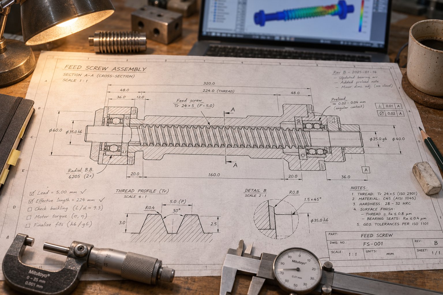
Every symptom in the diagnostic table from the previous section traces back to a geometry decision that was either made carelessly or skipped entirely. The fix isn't more troubleshooting experience — it's a repeatable design process that front-loads the right questions so geometry problems never reach the production floor. Whether you're specifying a plasticating screw for a single-screw extruder, sizing a twin screw conveyor for pharmaceutical blending, or engineering an inclined screw feeder for a grain elevator, the sequence is the same. Only the inputs change.
Here's that sequence, broken into phases that build on each other:
- Define the application scope and gather material data
- Document machine constraints and production targets
- Develop candidate geometries based on requirements
- Validate and iterate using simulation or empirical data
- Finalize material-of-construction and surface treatment specifications
- Document tolerances and release for manufacturing
Gathering Requirements and Defining Constraints
Skipping or shortcutting this phase is how the majority of geometry mismatches originate. Before any flight depth or pitch value is chosen, the engineering team needs answers to two categories of questions: what does the material demand, and what does the machine allow?
The material side draws directly from the property checklist covered earlier — bulk density, particle size distribution, moisture content, abrasiveness, friction coefficients, and (for plasticating applications) the full rheological profile including melt temperature range, viscosity curves, and degradation thresholds. As NC State Extension's extrusion processing guide emphasizes, a thorough knowledge of ingredient properties and functionality is necessary before preparing a screw configuration — especially information on the material's behavior when subjected to heat and shear conditions. A shear-sensitive material extruded with a high-shear screw profile, for instance, often fails to form a stable product. That kind of fundamental mismatch is caught here or caught nowhere.
The machine side is equally non-negotiable. Barrel diameter fixes the screw's outer dimension. Available barrel length sets the maximum L/D ratio. Drive motor power and torque curves limit how aggressively the screw can work the material. Temperature control capability — number of zones, heating and cooling capacity — constrains how much the geometry can rely on barrel heat versus shear-generated heat. For retrofit projects, the existing barrel condition matters too: a worn barrel with enlarged bore diameter changes the effective flight clearance of any new screw installed into it.
Production targets complete the picture. What mass throughput is required? At what screw speed range? With what tolerance on output variation? For a micro screw conveyor dosing milligrams of active pharmaceutical ingredient, the tolerance band might be fractions of a percent. For a high-capacity bulk discharge feeder, a five-percent variation might be perfectly acceptable. These targets set the performance criteria that every downstream geometry decision must satisfy.
Iterating on Geometry and Validating the Design
With requirements documented, engineers translate them into candidate geometries. This is where the parameters from earlier sections converge into a coherent screw specification: zone lengths proportioned to the material's melting or compaction behavior, compression ratios matched to the bulk-to-melt density change, feed zone depths sized for the feedstock's bulk density and particle characteristics, pitch profiles chosen for uniform withdrawal or maximum conveying efficiency, and mixing sections selected and placed to address specific homogeneity requirements.
The first candidate is rarely the final answer. Iteration is inherent in the process. A compression ratio that looks right on paper may generate more shear heat than the material's degradation window allows. A metering zone depth optimized for pressure stability at one throughput may surge at a higher target rate. A variable-pitch inlet designed for one hopper geometry may not distribute withdrawal evenly under a different bin configuration.
Modern simulation tools — including CFD-based approaches that model the coupled flow, pressure, and temperature fields inside the screw channel — accelerate this iteration significantly. Research presented at the 2026 International Conference on Aerospace Engineering and Materials Technology demonstrated exactly this kind of framework: by combining computational fluid dynamics with genetic algorithm optimization, researchers systematically explored screw geometric configurations for a non-Newtonian material, achieving a 123% increase in volume flow rate compared to the initial configuration while maintaining stable pressure and thermal safety constraints. That study optimized outlet core diameter, pitch, wedge angles, and thread width simultaneously — illustrating how multiple geometry parameters interact in ways that single-variable experimentation can't capture.
Not every project justifies full CFD analysis. For many applications, empirical experience and established design heuristics provide sufficient starting points. Retrofit scenarios carry a built-in advantage here: existing performance data — throughput logs, pressure traces, melt temperature profiles, wear patterns — directly reveals where the current geometry falls short and guides targeted improvements rather than wholesale redesigns.
For extrusion and injection molding teams evaluating application-specific screw geometry, services like NANHAIYA's custom screw design follow this same iterative methodology — their engineers review flight depths, compression ratios, mixing sections, materials, and surface treatments against the polymer's behavior, machine dimensions, temperature limits, and production targets before moving to manufacturing. That structured evaluation is one resource teams can use when the combination of material properties, machine constraints, and performance goals exceeds what general-purpose screw catalogs can address.
Moving from Design to Manufacturing
A validated geometry is a set of numbers. Turning those numbers into a functioning screw requires a final translation step that bridges engineering intent and fabrication reality.
Material-of-construction selection happens here — not as an afterthought, but as a decision informed by everything the requirements phase revealed. The feedstock's abrasiveness, corrosiveness, and processing temperature dictate whether the screw starts as 4140 alloy steel, 17-4 PH stainless, or a nickel-based superalloy. Surface treatments — nitriding, hard-chrome, tungsten carbide flight inlays, CVD coatings — are specified to match the dominant wear mechanism identified during the material characterization phase.
Tolerance documentation closes the loop. Critical dimensions — flight OD, root diameter at each zone, flight-to-barrel clearance, pitch spacing — receive specific tolerance bands tied to functional requirements. As the custom fastener engineering community consistently advises, only dimensions that are functionally critical should receive tight tolerances. Over-specifying tolerances on non-critical features inflates manufacturing cost and lead time without improving performance. The discipline is to identify which dimensions directly affect conveying efficiency, pressure stability, or wear life — and hold those tight while allowing standard tolerances everywhere else.
The finished specification package — geometry, materials, surface treatments, tolerances, and inspection criteria — is what separates a screw that's engineered from one that's merely manufactured. Every phase in this process exists because skipping it produces the exact symptoms detailed in the troubleshooting section: surging, premature wear, bridging, thermal degradation, and output that never quite meets the target. The investment in front-end rigor pays for itself not in one production run, but across the full service life of a screw that was designed right the first time.
Frequently Asked Questions About Feed Screw Design
1. What is the most important factor in feed screw design?
Material properties are the single most important starting point. Bulk density determines required channel volume, particle size sets minimum clearances, moisture and abrasiveness influence construction choices, and friction coefficients between the barrel wall and screw root directly control solids conveying efficiency. Engineers should document a full material property checklist — including flow characteristics, temperature sensitivity, and corrosiveness — before selecting any geometry parameter. A screw designed around verified material data consistently outperforms one sized from generic catalog defaults, because every dimension from feed zone depth to compression ratio must reflect how the specific feedstock behaves under real processing conditions.
2. How do compression ratio and L/D ratio affect screw performance?
The L/D ratio controls how much processing occurs between the feed throat and discharge. Shorter ratios (around 20:1) suit simple conveying, while longer ratios (24:1 to 34:1) provide the residence time needed for melting, mixing, and venting in plasticating applications. Compression ratio — the feed zone channel volume divided by the metering zone channel volume — governs material compaction and shear heat generation. Lower ratios near 2:1 protect heat-sensitive polymers like PVC, while higher ratios up to 4:1 handle tougher crystalline resins. These two parameters interact: a high compression ratio paired with a long L/D can generate excessive shear and residence time, risking thermal degradation. Balancing them against the material's melt behavior and thermal limits is essential.
3. What causes output surging in a screw feeder or extruder?
Cyclic output surging usually traces back to three geometry-related causes. First, a compression ratio mismatched with the material's density change from solid to melt creates uneven pressure buildup and release. Second, a metering zone that is too short fails to stabilize pressure before the discharge point. Third, solids conveying instability in the feed zone — often from inadequate friction differential between the barrel wall and screw root — causes intermittent feeding. Surging that worsens at higher screw speeds typically signals that the screw's melting or conveying capacity has been exceeded. Diagnosing the root cause requires checking whether the system is flood-fed or starve-fed, since each mode shifts where instability most likely originates.
4. When should variable-pitch flights be used instead of standard full-pitch flights?
Variable-pitch flights are most valuable when a screw must withdraw material uniformly from a hopper, bin, or silo. With a constant-pitch screw beneath a hopper opening, the flights closest to the back wall preferentially fill first, creating uneven draw-down that promotes bridging and rat-holing. Variable-pitch designs start with a tighter pitch at the inlet and progressively widen toward the discharge, so each successive flight gains slightly more volumetric capacity. This evens out withdrawal across the full hopper opening. They are standard in gravimetric and volumetric screw feeders for bulk solids handling, live-bottom bin dischargers, and any application where consistent material extraction from storage is critical to downstream process stability.
5. How do I choose the right screw construction material and surface treatment?
Selection depends on the feedstock's abrasiveness, corrosiveness, and processing temperature. For general-purpose extrusion of non-abrasive polymers, AISI 4140 alloy steel with flame-hardened flights is a cost-effective baseline. Abrasive fillers like glass fiber demand tungsten carbide or Stellite flight-tip hard-facing. Corrosive materials such as fluoropolymers require nickel-based alloys like Inconel or Hastelloy. Surface treatments add targeted protection: nitriding provides moderate wear resistance at low cost, hard chrome improves material release on screw roots, and CVD coatings deliver pore-free protection for severe combined abrasion and corrosion. Structured engineering review services — such as NANHAIYA's custom screw design evaluation at nhyscrews.com — can help match metallurgy and coatings to specific polymer behavior and machine conditions before manufacturing begins.
Written by
Nanhaiya Technical Team
Zhoushan Nanhaiya Plastic Machinery Co., Ltd.
The Nanhaiya technical team supports screw and barrel manufacturing projects through application review, technical communication, custom manufacturing coordination, and production and quality control.
Discuss Your Application
Related Articles
More insights on screw barrel technology and plastics processing.

Injection Molding Color Mixing: From Streaks to Flawless Consistency
Nov 19, 2026
Master injection molding color mixing with expert guidance on colorant types, screw design, process parameters, defect troubleshooting, and Delta E QC protocols.
Read Article
Wrong Extruder Breaker Plate? Spot the Signs Before Scrap Piles Up
Nov 19, 2026
Learn how to select, size, and maintain your extruder breaker plate. Covers hole geometry, pressure drop, polymer-specific specs, and troubleshooting tips.
Read Article
Injection Molding Melt Temperature: Why Your Barrel Settings Lie
Nov 19, 2026
Learn why barrel set points lie about injection molding melt temperature. Complete resin chart, measurement methods, defect troubleshooting, and optimization steps.
Read ArticleLooking for something else?
Search by material, symptom or product and jump straight to the relevant page.
These are navigation suggestions based on keyword matching — not a quotation, not a delivery commitment, and not a substitute for engineering review. Final specification is confirmed by our engineers against your drawings and processed material.
Need help with screw barrel selection?
Share your machine model, processed material and application. Our team can help with pricing and technical support.