

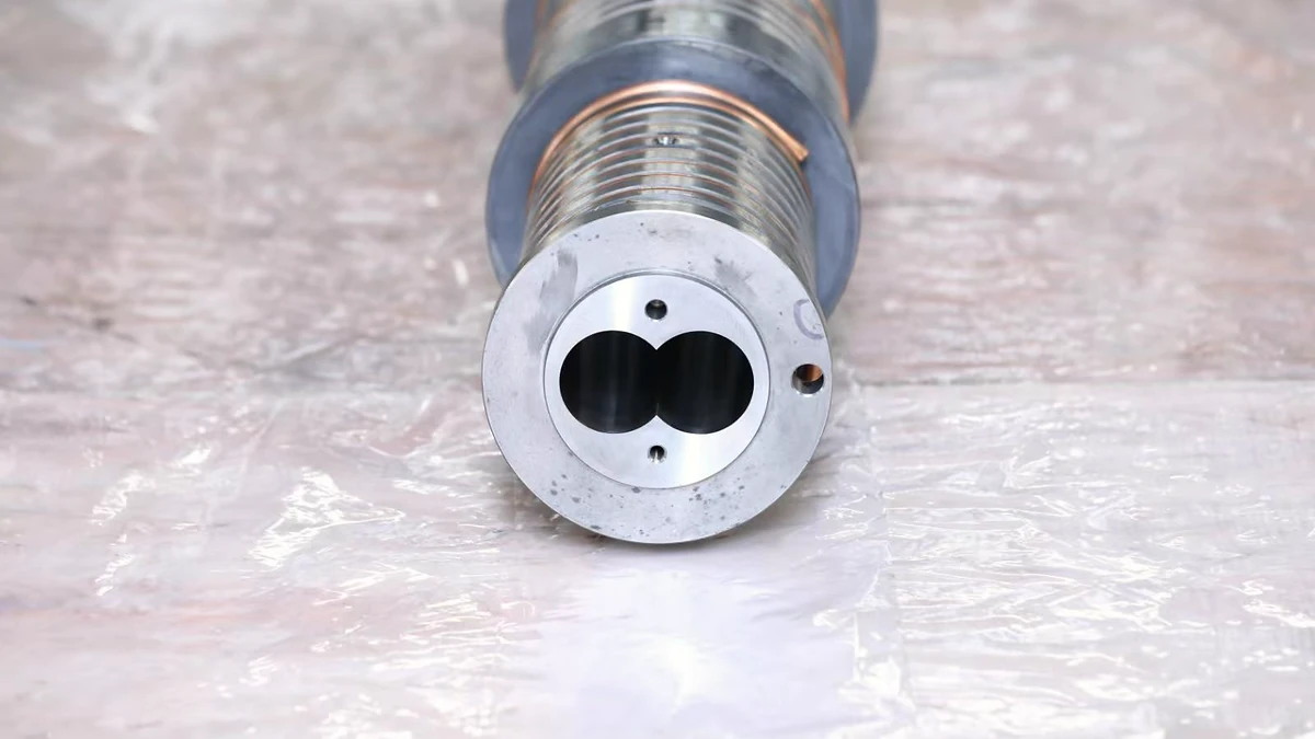
What Gross Melt Fracture Is and Why It Destroys Extrudate Quality
Imagine pulling a freshly extruded strand from your die and finding it twisted, warped, and chaotically deformed beyond recognition. Not a subtle surface ripple you could sand away — the entire cross-section is distorted, as though the melt stream itself tore apart on its way through the die. That is gross melt fracture in action, and it is one of the most damaging flow instabilities in polymer extrusion.
Defining Gross Melt Fracture in Polymer Extrusion
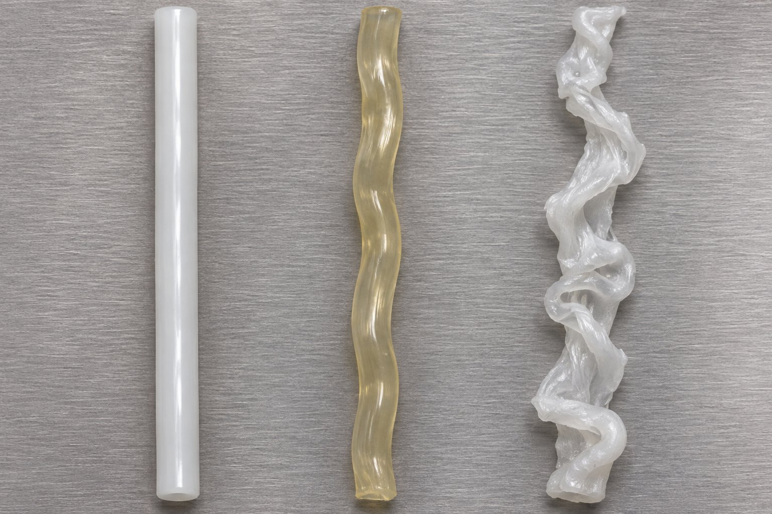
Gross melt fracture is a severe flow instability in polymer extrusion in which the entire melt stream undergoes large-amplitude, irregular distortion as it passes through the die entrance, producing extrudate with gross volumetric deformation rather than surface-only defects.
What separates this defect from milder extrusion irregularities is its volumetric nature. Minor surface roughness — sometimes called sharkskin — leaves the extrudate dimensionally intact beneath a slightly textured skin. Gross melt fracture, by contrast, disrupts the entire melt cross-section. The resulting extrudate can appear helically twisted (a phenomenon sometimes called "corkscrewing"), or it can exhibit chaotic, aperiodic distortion so severe that no amount of downstream correction can salvage the product. Research compiled by Dealy and Kim helped standardize this terminology within polymer rheology, distinguishing GMF — also referred to as volume melt fracture — from the surface-only instabilities that arise at the die exit.
The root cause lies upstream of the die land, in the converging entry region where the melt accelerates from a wide barrel or reservoir into the narrow die orifice. At sufficiently high throughput, the extensional deformation in this contraction zone exceeds what the polymer can accommodate elastically, and the melt stream ruptures internally. The onset of extrusion instabilities has been roughly estimated to occur at wall shear stresses between 0.1 and 2 MPa, though exact critical values depend on polymer structure, temperature, and die geometry.
Why GMF Costs Extrusion Plants Real Output
For processors, GMF is not an academic curiosity — it is a production killer. When it strikes, operators face a narrow set of unpleasant choices: reduce throughput to drop below the critical flow rate, scrap every meter of distorted extrudate, or halt the line entirely to troubleshoot. Each option eats into output and margin. The occurrence of these irregularities not only limits production rates but also restricts the market penetration of new polymer resins that might otherwise run at higher speeds.
Yet reliable, freely accessible information on GMF mechanisms, onset criteria, and prevention strategies remains surprisingly scarce. Most detailed treatments sit behind journal paywalls, while freely available overviews tend to stop at a single-paragraph definition. This resource bridges that gap — offering a consolidated, technical-but-accessible guide that covers everything from the rheological science behind the instability to actionable die-design and process-tuning strategies you can apply on your production floor.
How This Resource Is Organized
The article follows a deliberate mechanism-to-mitigation arc, structured so each section builds naturally on the last:
- Definition — what gross melt fracture is and how it differs from surface defects
- Disambiguation — a detailed sharkskin-versus-GMF comparison to prevent misdiagnosis
- Mechanisms — die entrance flow dynamics, vortex formation, and extensional strain
- Onset criteria — the four competing approaches for predicting when GMF begins
- Rheometry — how capillary and extensional measurements detect GMF thresholds
- Polymer comparison — how polyethylene, polypropylene, polystyrene, and other resin families differ in susceptibility
- Mitigation — die design changes, process adjustments, processing aids, and upstream melt-quality factors
Whether you are troubleshooting a live production issue or evaluating a new resin grade, that progression will take you from "what is happening" to "how do I fix it" — and, more importantly, help you avoid the misdiagnosis that sends too many processors chasing the wrong corrective action.
Sharkskin vs Gross Melt Fracture and Why the Distinction Matters
That misdiagnosis problem mentioned above? It almost always starts here — with processors lumping two fundamentally different defects under the single label "melt fracture" and then applying a one-size-fits-all fix. Sharkskin and gross melt fracture share a name, but they originate at opposite ends of the die, affect different portions of the extrudate, and demand entirely different corrective strategies. Treating them as interchangeable is like prescribing cough syrup for a broken rib.
Sharkskin Melt Fracture Originates at the Die Exit
Sharkskin is a surface-only instability. It develops right at the die exit lip, where the polymer melt transitions from a no-slip wall boundary condition inside the die land to free-surface flow in open air. During that abrupt transition, the outermost layer of the melt stretches rapidly as it accelerates from near-zero velocity at the wall to the plug-flow velocity of the extrudate core. When the local extensional stress at the surface exceeds the melt's cohesive strength, the skin tears periodically.
The visual signature is distinctive: fine, regular, transverse ridges running perpendicular to the extrusion direction — a matte, "orange-peel" texture on an extrudate that is otherwise dimensionally correct. You'll notice that cutting the extrudate open reveals a perfectly normal interior. The cross-section retains its intended shape and dimensions; only the outermost skin is affected. For common polyolefins, sharkskin typically appears when wall shear stress reaches roughly 0.1 to 0.4 MPa at the die exit.
Because the mechanism is tied to the exit region, sharkskin responds well to exit-focused remedies: raising die-land temperature to lower local viscosity, applying fluoropolymer processing aids that coat the die wall and promote slip, or modifying the die lip geometry to soften the velocity transition. These fixes work precisely because they target the surface-tearing event at the downstream end of the die.
Gross Melt Fracture Originates at the Die Entrance
Gross melt fracture is an entirely different beast. It originates upstream, in the converging flow region where the melt funnels from the wide barrel or adapter into the narrow die orifice. Here, the dominant deformation mode is extensional — the melt is being stretched, not just sheared. When throughput climbs high enough, the elastic strain stored in the converging melt exceeds the polymer's cohesive strength, and the melt stream ruptures internally.
The result is not a surface blemish but a volumetric catastrophe. The entire cross-section of the extrudate emerges distorted — helically twisted, irregularly wavy, or chaotically deformed. There is no "good interior" hiding beneath a rough skin. Every millimeter of the extrudate is compromised, making the product unsalvageable. As extrusion troubleshooting literature confirms, the severity ladder progresses from mild sharkskin through stick-slip (bamboo) distortion and finally to this gross, whole-extrudate deformation that represents the most extreme form of the instability.
The table below puts the two defects side by side so you can diagnose which one you are actually dealing with:
| Feature | Sharkskin Melt Fracture | Gross Melt Fracture |
|---|---|---|
| Origin Location | Die exit (lip region) | Die entrance (converging contraction zone) |
| Defect Scope | Surface only — interior cross-section intact | Volumetric — entire cross-section distorted |
| Visual Appearance | Fine, regular transverse ridges; matte texture | Helical twist, chaotic waviness, or gross irregular distortion |
| Onset Shear Stress Range | ~0.1 - 0.4 MPa (polyolefins) | Higher than sharkskin onset; typically above the stick-slip regime |
| Primary Mechanism | Surface tearing at the no-slip to free-surface transition | Elastic instability and internal melt rupture in extensional flow |
Why Confusing the Two Leads to Wrong Corrective Actions
Here is where misdiagnosis gets expensive. Imagine you spot severe extrudate distortion and assume it is a sharkskin problem. You raise the die-land temperature, install a fluoropolymer processing aid, maybe even re-polish the die lip. Days pass, additive inventory is consumed, and production stays down — because the instability is not happening at the exit. It is happening upstream, in the contraction zone, where none of those exit-focused interventions reach.
The reverse scenario is equally wasteful. A processor dealing with genuine sharkskin might invest in an expensive streamlined die entry redesign — a modification that targets entrance-region extensional flow — when a simple temperature bump at the die lip or a few hundred ppm of fluoroelastomer would have cleared the surface defect in minutes. Metallocene-type polyolefins, for instance, are particularly susceptible to melt fracture due to their narrow molecular weight distribution and reduced shear-thinning behavior, as industry troubleshooting cases have documented. Knowing whether the defect is surface-level or volumetric determines whether the fix should focus on the die lip or the die entry.
Correct disambiguation is not a nice-to-have — it is the essential first diagnostic step. Before adjusting a single process parameter, examine the extrudate carefully. If the cross-section is dimensionally correct but the surface feels rough or matte, you are likely dealing with sharkskin. If the entire profile is twisted, wavy, or chaotically deformed, the problem almost certainly traces back to the entrance region. That single observation — surface defect versus volumetric distortion — points you toward the right family of corrective actions and saves you from chasing solutions that cannot possibly work.
The logical next question, of course, is what exactly happens in that converging entrance zone that causes the melt to lose coherent flow in the first place. The answer lies in the interplay of extensional deformation, vortex dynamics, and elastic energy storage — forces that build silently upstream of the die land.

Die Entrance Flow Dynamics That Trigger Gross Melt Fracture
Picture what a polymer melt actually encounters when it approaches a die. It has been traveling through a relatively wide barrel or adapter channel — moving slowly, under moderate stress. Then, within a few millimeters, it must squeeze into an orifice that may be ten, twenty, or even fifty times smaller in cross-sectional area. That abrupt geometric contraction is where gross melt fracture is born, and understanding the physics of what happens there is the key to predicting — and preventing — the instability.
Converging Flow and Extensional Deformation at the Contraction Zone
When melt flows from a wide reservoir into a narrow die orifice, conservation of mass forces it to accelerate. The velocity on the centerline can increase by an order of magnitude over just a few millimeters of travel. Laser-Doppler velocimetry (LDV) measurements on LDPE melts flowing into a slit die have demonstrated this vividly: velocity along the channel axis at 1 mm above the entrance plane was roughly eight times higher than at 20 mm, revealing an intense velocity gradient concentrated in the final approach to the orifice.
That steep velocity gradient translates directly into extensional — or elongational — deformation. Unlike shear, where fluid layers slide past each other, extensional deformation stretches the melt along the flow axis. Imagine pulling taffy: the material gets longer and thinner. In the converging zone, this stretching is not gentle. The same LDV data showed elongational rates peaking at approximately 12 s-1 right at the slit entrance, with a total Hencky strain of about 2.5 accumulating within just a few tenths of a second.
Two geometric variables govern how severe this extensional strain becomes:
- Contraction ratio — the ratio of barrel (or reservoir) cross-sectional area to die orifice area. A higher ratio means the melt must accelerate more violently, generating steeper extensional strain rates.
- Entry angle — the angle at which the channel walls converge. A flat-entry die (180° included angle) forces the melt to self-select its own converging streamlines, concentrating deformation unevenly. A tapered entry spreads the acceleration over a longer path.
At moderate throughput rates, the polymer accommodates this extensional deformation elastically. The long-chain molecules stretch, store energy, and — if given enough time in the die land — relax back toward equilibrium. But there is a threshold. When throughput climbs high enough that the elastic strain stored in the converging region becomes irrecoverable, the melt can no longer maintain coherent flow. It fractures internally, and the chaotic, volumetric distortion characteristic of gross melt fracture appears at the die exit.
Research on recoverable extensional flow supports this picture. Because the deformation times in the entrance region are extremely short — fractions of a second — most of the total Hencky strain is elastic rather than viscous. For an LDPE stretched to a total Hencky strain of 3 at 1 s-1, recoverable strain reached 2.1. Under the even shorter deformation times of actual entrance flow, the elastic fraction is expected to be still larger. The melt, in other words, is behaving more like a rubber band than a viscous fluid — and rubber bands snap when you stretch them too far.
Vortex Formation and Elastic Instability
The extensional strain on the centerline is only part of the story. Look at what happens in the corners of a flat-entry die — the dead zones where the wide reservoir meets the narrow orifice at a sharp right angle. Melt in these corner regions cannot flow directly into the die; instead, it circulates in secondary-flow vortices, slowly rotating in recirculating loops.
These corner vortices are not benign. The melt trapped in them is continuously being loaded elastically as the main flow stream rushes past. Under stable conditions, the vortices maintain a steady, symmetric shape. But as throughput increases, the elastic loading in the vortex region intensifies until the structures become unstable and begin to oscillate.
Particle image velocimetry (PIV) studies on polydimethylsiloxane (PDMS) melts flowing through axisymmetric contractions have captured this transition in striking detail. Under stable conditions, the upstream flow field was symmetric and steady. As throughput crossed a critical threshold, instabilities first appeared near the centerline and close to the orifice plane — exactly where extensional strain rates peak. These instabilities then spread radially, progressively invading the entire upstream flow field until it lost all symmetry. The researchers described the resulting two-dimensional projection as resembling a "knitting system," with the flow expected to exhibit spiraling motion in three dimensions.
The magnitude of these fluctuations is remarkable. On the flow axis, instantaneous velocity fluctuations reached ±30% of the mean value. Away from the centerline, fluctuations climbed to ±105% of the mean — meaning the local flow direction was essentially reversing at some instants. When a melt stream this chaotic feeds into the die capillary, the extrudate emerges with the large-scale, irregular distortion that defines gross melt fracture. The die land cannot "smooth out" upstream chaos of this magnitude; it simply passes the distorted melt through and delivers a ruined product.
A critical detail from the PIV work: the instability frequency remained approximately constant as flow rate increased, while the amplitude grew. This means the onset is relatively sharp — once you cross the threshold, the severity escalates quickly with further throughput increases, which matches the practical experience of extrusion operators who report that GMF seems to appear "all at once" rather than building gradually.
Role of Entry Angle and Die Geometry
If the converging zone is where the instability originates, then reshaping that zone is the most direct geometric lever for delaying onset. Tapered or streamlined die entries reduce extensional strain rates by spreading the contraction over a longer axial distance. Instead of forcing the melt to accelerate from reservoir velocity to capillary velocity within a millimeter or two at a sharp 180° corner, a conical or trumpet-shaped entry distributes that acceleration over tens of millimeters. The peak elongational rate drops, the elastic strain stored per unit of throughput decreases, and the critical flow rate for gross melt fracture shifts upward.
The effectiveness of this approach has been confirmed experimentally. Piau et al. demonstrated that introducing a porous medium at the die entry attenuated or eliminated the defect — partly through chain disentanglement, but also because the porous structure imposed pre-shearing that reduced the elongational strains the melt would otherwise experience at the contraction plane. While a porous-medium insert is not a standard production solution, it illustrates the principle: anything that softens the extensional deformation at the entry suppresses the instability.
Die land geometry matters too, though as a secondary factor. The L/D ratio — die land length divided by diameter — determines how much time the melt spends inside the capillary after passing through the entry zone. A longer die land gives the elastically loaded melt more time to relax stored strain through viscous dissipation before it exits. This does not prevent the entrance instability itself, but it can attenuate the severity of distortion in the final extrudate. The trade-off is increased pressure drop and energy consumption.
Here is a summary of the key geometric variables that influence onset:
- Contraction ratio — higher ratios intensify extensional strain; reducing the ratio (where product geometry allows) lowers GMF risk
- Entry angle — flat entries (180°) are worst-case; tapered cones (30°–60° half-angle) or streamlined trumpet profiles delay onset significantly
- Die land L/D — longer die lands allow partial relaxation of entrance-region elastic strain, reducing extrudate distortion severity
- Die land surface finish — while primarily relevant to wall-slip and sharkskin behavior, surface condition can influence the stress state at the transition from entry to land
Geometry, however, can only delay the threshold — it cannot eliminate it. Every polymer has a finite capacity to store elastic energy, and at some throughput rate, that capacity will be exceeded regardless of how gently the entry is shaped. The question then becomes: what specific rheological properties determine where that threshold falls, and how do you measure them? The answer involves two interrelated material characteristics — extensional viscosity and recoverable strain — that together define a polymer's tolerance for the converging deformation that the die entrance demands.
Extensional Rheology and Melt Elasticity Behind GMF
Every polymer melt has a breaking point — not in the familiar sense of a solid snapping under tension, but in the sense that a flowing, viscoelastic liquid can store so much elastic energy that it tears itself apart from within. That internal rupture is the engine driving gross melt fracture. Understanding the two rheological properties that govern it — extensional viscosity and recoverable strain — transforms the instability from a mysterious production gremlin into a predictable, measurable phenomenon.
Extensional Viscosity and Strain Hardening
When you push a polymer melt through a shear flow — say, along the die land — neighboring layers slide past each other. The resistance to that sliding is shear viscosity, and it is the property most extrusion processors know by heart. But at the die entrance, shear is not the dominant deformation mode. The melt is being stretched — pulled along the flow axis as it accelerates into the narrowing orifice. The resistance to that stretching is called extensional (or elongational) viscosity, and it behaves very differently from its shear counterpart.
For a perfectly Newtonian fluid, the extensional viscosity is exactly three times the shear viscosity — a relationship known as the Trouton ratio. Polymer melts, however, are not Newtonian. At large strains and high strain rates, their extensional viscosity can deviate enormously from that simple 3:1 prediction. The direction of that deviation — upward or downward — depends heavily on molecular architecture, and it has profound consequences for gross melt fracture susceptibility.
Imagine stretching two different polyethylene melts at the same rate. One is a low-density polyethylene (LDPE) with extensive long-chain branching. The other is a linear low-density polyethylene (LLDPE) with a narrow molecular weight distribution and no significant branching. As you increase the extensional strain, something striking happens:
- LDPE (branched) — the extensional viscosity climbs steeply above the linear viscoelastic envelope at high strains and strain rates, a behavior called strain hardening. The branch points act as topological anchors, resisting chain disentanglement and forcing the melt to stiffen as it stretches. Research using SER extensional rheometry on PE melts has documented this clearly: LDPE shows a pronounced viscosity increase at large Hencky strains, stabilizing the melt against rupture.
- LLDPE (linear) — the extensional viscosity follows the linear viscoelastic envelope closely or even falls slightly below it (strain softening). Without branch-point anchors, the linear chains slip past one another more readily under extensional stress. The melt reaches its cohesive limit sooner.
This difference is directly visible in comparative elongation viscosity measurements: LDPE exhibits the dramatic upturn characteristic of strain hardening, while LLDPE traces a path much closer to three times the zero-shear viscosity, reaching steady state faster with little or no upward deviation. The practical consequence? LDPE can tolerate the extensional deformation at the die entrance over a wider throughput range before the melt fractures, while linear polyethylenes hit the failure threshold at lower flow rates.
Molecular weight distribution plays a supporting role. Uniaxial extensional studies of multimodal linear PE blends have shown that even without long-chain branching, the presence of a well-separated ultra-high molecular weight (UHMW) component — as little as a few weight percent — can introduce measurable strain hardening. The extremely long chains act as a kind of molecular reinforcement, stretching under extensional flow and resisting the rapid chain disentanglement that leads to rupture. A critical Hencky strain rate marks the onset of this hardening behavior, and it shifts depending on UHMW content and molecular weight distribution breadth. In other words, the extensional viscosity response is not a fixed material constant — it is tunable through molecular design.
For GMF prediction, the key takeaway is this: the onset of gross melt fracture in the die entrance region correlates with a critical extensional stress or strain at which the melt can no longer sustain coherent stretching flow. Polymers that strain-harden delay that critical point; polymers that strain-soften reach it sooner.
Recoverable Strain and First Normal Stress Difference
Extensional viscosity tells you how strongly the melt resists being stretched. But there is a second, equally important piece of the puzzle: how much of that deformation is stored elastically and can snap back if you release the stress. This is melt elasticity, and it is the property that determines whether the energy pumped into the melt at the die entrance dissipates harmlessly or builds to a catastrophic release.
Sounds abstract? Think of it this way. When you deform a polymer melt, part of the input energy goes into permanently rearranging molecular chains — that is the viscous component, and it is lost as heat. The rest goes into temporarily stretching and distorting the coiled chain conformations — that is the elastic component, stored as recoverable strain. If you suddenly removed all external forces, the elastic portion would drive the melt to partially spring back toward its original shape. You see this every time an extrudate swells as it exits a die — that die swell is recoverable elastic strain expressing itself.
Two laboratory-measurable quantities capture this elasticity:
- Recoverable shear strain (SR) — the amount of strain that recovers after the stress is removed. A melt with SR = 5 stores five units of elastic strain for every unit of applied shear. The higher the recoverable strain, the more elastic energy the melt is banking during flow.
- First normal stress difference (N1) — in a shear flow, viscoelastic fluids push outward along the direction perpendicular to the shearing surfaces. N1 quantifies this "hoop stress" effect and is directly proportional to stored elastic energy. Cone-plate rheometry of HDPE melts has shown that even resins with nearly identical shear viscosity profiles can have dramatically different N1 values — a difference that correlates with processing behavior including die swell and flow stability.
Why does this matter for gross melt fracture? Because the converging flow at the die entrance is an extraordinarily efficient mechanism for pumping elastic energy into the melt. The deformation times are extremely short — fractions of a second — and the strains are large. Under these conditions, the melt behaves far more like an elastic solid than a viscous liquid. Most of the Hencky strain accumulated in the entrance zone is recoverable rather than dissipated. The melt is, effectively, a loaded spring.
The storage modulus G', measurable through oscillatory shear, provides another window into this elastic character. Application studies on HDPE pipe extrusion have demonstrated that even small variations in melt elasticity — visible as differences in G' at low frequencies — correlate with surface quality defects. When the elasticity is too high, the melt stores too much deformation energy during passage through the die, and defects emerge. Gross melt fracture represents the extreme end of this spectrum: not just surface roughness, but wholesale volumetric failure driven by elastic energy that overwhelms the melt's internal cohesion.
From Elastic Energy Storage to Melt Rupture
The two threads — extensional viscosity behavior and recoverable elastic strain — converge into a single physical picture of how gross melt fracture actually happens. Here is the sequence, step by step:
- The melt enters the converging zone upstream of the die orifice and begins to accelerate.
- Extensional deformation dominates. Molecular chains are stretched along the flow axis, storing elastic energy in their distorted conformations.
- Because the deformation times are extremely short, most of this strain is elastic (recoverable) rather than viscous (dissipated). The melt is accumulating internal stress rapidly.
- If the polymer strain-hardens — as LDPE does with its long-chain branching — the rising extensional viscosity acts as a stabilizing mechanism, distributing the load more uniformly and resisting localized rupture. The threshold for failure shifts to higher throughputs.
- If the polymer does not strain-harden — as many linear polyethylenes, polypropylenes, and other commodity resins do not — the extensional viscosity remains flat or drops, offering no self-stabilizing resistance. The elastic strain accumulates unchecked.
- When the recoverable strain exceeds a critical value — or equivalently, when the stored elastic energy exceeds the melt's cohesive strength — the material can no longer maintain a continuous, coherent flow. The melt fractures internally, and the disrupted stream passes through the die land as a chaotically distorted mass.
The SER platform measurements on UHMWPE provide a vivid illustration of this failure mode. Highly entangled linear samples showed greatly reduced strains to failure during extensional testing — consistent with the predictions of the Considere criterion for necking instability. Beyond a critical imposed Hencky strain, the tensile stresses relaxed nonlinearly and the material became unstable to viscoelastic rupture. The same physics applies at the die entrance, where the contraction geometry imposes large extensional strains in very short times.
Gross melt fracture occurs when the elastic strain stored in the converging melt exceeds the polymer's cohesive strength, resulting in internal rupture of the melt stream.
This principle has a powerful practical implication: anything that reduces the elastic energy stored at the entrance — lower throughput, higher melt temperature to accelerate relaxation, streamlined die geometry to reduce peak extensional rates, or selection of a resin with stronger strain-hardening character — pushes the failure threshold further away. Conversely, anything that increases elastic loading — higher throughput, lower temperatures, abrupt flat entries, or narrow-MWD linear resins — pulls it closer.
The challenge, of course, is quantifying exactly where that threshold falls for a specific polymer under specific conditions. Rheologists have proposed not one but four distinct criteria for predicting GMF onset — each measuring a different aspect of the same underlying physics, each with its own strengths and blind spots. Choosing the right criterion for your material and your process can mean the difference between a reliable operating window and an expensive guessing game.

Four Competing Criteria for Predicting GMF Onset
Knowing why gross melt fracture happens is one thing. Knowing exactly when it will happen — for your specific resin, at your specific processing conditions — is what actually keeps a production line running. Rheologists have tackled this prediction problem from four different angles, each measuring a different facet of the same underlying elastic-rupture physics. No single criterion has won universal acceptance, which is why processors benefit from understanding all four. Below is the most complete freely accessible comparison available.
Shear-Stress-Based Criterion
This is the oldest and most widely used approach, and its appeal lies in simplicity. The idea: gross melt fracture initiates when the apparent wall shear stress inside the die capillary exceeds a critical value. You measure pressure drop across the die, calculate wall shear stress using the Poiseuille relationship, and compare the result to a known threshold.
For polyethylenes, that threshold is often reported in the range of 0.1 to 0.5 MPa, though exact values vary with polymer grade, molecular weight distribution, and temperature. Research on LDPE, for example, places the critical wall shear stress for the onset of gross fracture at approximately 0.1 MPa (105 Pa), while LLDPE exhibits sharkskin at roughly 0.18 MPa and slip-stick behavior around 0.3 MPa before progressing to severe distortion at still higher stresses.
The strength of this criterion is practical convenience. Every capillary rheometer and most production extruders can deliver a wall shear stress measurement, making the threshold easy to check on the fly. The limitation, however, is mechanistic. Wall shear stress is calculated from conditions along the die land — a region dominated by shear flow. Yet gross melt fracture originates upstream, in the extensional flow field at the die entrance. The shear-stress criterion works as an empirical flag, but it does not directly describe the physical event causing the instability. As a result, its predictive accuracy can falter when die geometry changes significantly — a tapered entry, for instance, may alter the entrance flow field without changing the wall shear stress in the die land at all.
Tensile-Stress-Based Criterion
If the instability is born in extensional flow, shouldn't the onset criterion be based on extensional stress rather than shear stress? That is precisely the logic behind this second approach. Here, the prediction shifts from what happens along the die wall to what happens in the converging melt upstream of it: gross melt fracture initiates when the extensional (tensile) stress in the contraction zone reaches the melt's tensile strength.
The mechanistic justification is strong. You'll recall from the previous discussion that the converging flow field imposes large elongational strains on the melt in very short times, and that most of those strains are elastic. The tensile-stress criterion captures this reality directly — it asks whether the stretching force in the entrance region exceeds the material's capacity to hold itself together. When it does, internal rupture occurs, and the disrupted melt stream enters the die land already fractured.
Measuring the relevant tensile stress, however, is considerably harder than reading a pressure transducer on the die land. It requires either an extensional rheometer capable of capturing transient stress growth at high strain rates, or a computational fluid dynamics (CFD) model of the contraction flow field calibrated against experimental velocity data. This added complexity is why the shear-stress approach remains more popular on production floors, even though the tensile-stress criterion offers a more physically grounded prediction.
A practical middle ground exists. Some researchers use Cogswell's analysis — a well-known method that estimates entrance pressure drop and converts it into an apparent extensional viscosity and extensional stress. This approach extracts entrance-region information from standard capillary rheometry data, bridging the gap between the convenience of the shear-stress method and the mechanistic relevance of the tensile-stress method.
Recoverable-Strain and Wall-Slip Criteria
Two additional criteria round out the picture, each targeting a different measurable consequence of the elastic energy buildup that drives gross melt fracture.
Recoverable-strain criterion. This approach defines the threshold in terms of how much elastic deformation the melt has stored. When recoverable shear strain — the portion of total strain that springs back after stress removal — exceeds a critical value, the melt can no longer dissipate elastic energy fast enough and ruptures internally. For many commodity polymers, the reported critical recoverable strain falls in the range of roughly 5 to 10, though the exact number depends on polymer architecture, temperature, and deformation history. The appeal of this criterion is its direct connection to the elastic energy storage mechanism described earlier. Its limitation is measurement difficulty: recoverable strain is typically determined from die swell measurements or constrained-recoil experiments on a rheometer, neither of which is a quick, in-line check.
Wall-slip criterion. At sufficiently high wall shear stresses, some polymer melts lose adhesion to the die surface entirely. The melt begins to slip intermittently — sticking, then releasing, then sticking again — producing the characteristic pressure oscillations and extrudate distortion of the stick-slip (bamboo) regime. Some rheological models attribute this behavior to a non-monotone relationship between shear stress and shear rate, where multiple flow rates become possible at a single wall stress. When the melt jumps between these flow states, the resulting instability can escalate into gross volumetric distortion. The wall-slip criterion predicts GMF onset as the point where adhesive failure at the die wall destabilizes the entire flow field. Its strength is that it accounts for the polymer-metal interface, which processing aids directly modify. Its weakness is that wall slip is not always the dominant mechanism — particularly for polymers like LDPE, where entry-vortex instability can trigger gross fracture without any sign of pressure oscillations, suggesting the melt fractures at the entrance before wall slip in the die land ever becomes relevant.
The table below puts all four criteria side by side so you can evaluate which is most useful for your specific diagnostic situation:
| Criterion Name | Measured Parameter | Mechanistic Basis | Strengths | Limitations |
|---|---|---|---|---|
| Shear-Stress | Wall shear stress in the die capillary (typically 0.1 - 0.5 MPa for PE) | Empirical correlation between die-land stress and extrudate distortion onset | Simple measurement; available from any capillary rheometer or instrumented die | Does not directly measure the entrance-region extensional event; accuracy shifts with die geometry changes |
| Tensile-Stress | Extensional stress in the converging entry zone | Internal melt rupture when tensile stress exceeds cohesive melt strength | Directly addresses the extensional mechanism at the die entrance | Requires extensional rheometry or CFD modeling; harder to measure in production settings |
| Recoverable Strain | Elastic strain recovered after stress removal (critical SR ~ 5 - 10) | Elastic energy storage exceeds dissipation capacity, triggering internal fracture | Directly linked to stored elastic energy; good correlation with melt elasticity indicators like N1 | Measurement requires die swell or recoil experiments; not an in-line metric |
| Wall Slip | Critical wall stress for adhesive failure at the polymer-metal interface | Loss of melt adhesion causes stick-slip instability escalating to gross distortion | Accounts for die-surface interactions; relevant where processing aids modify slip behavior | Not the dominant mechanism for all polymers (e.g., LDPE fractures at the entry without pressure oscillations); slip behavior is surface-dependent |
Which criterion should you rely on? The honest answer is: it depends on your polymer, your die, and your diagnostic resources. For day-to-day production monitoring, the shear-stress criterion remains the most practical first screen — it is fast, cheap, and reliable enough as an empirical flag. For resin development or die design optimization, the tensile-stress and recoverable-strain criteria offer deeper mechanistic insight. And if you are working with linear polyolefins that show pronounced stick-slip behavior, the wall-slip criterion may capture the dominant instability mode that the others miss.
In practice, experienced processors often use a layered approach: start with the shear-stress threshold from capillary rheometry, then refine the picture with extensional data and recoverable strain measurements when the stakes — or the ambiguity — justify the extra effort. That layered diagnostic strategy, naturally, demands the right rheological tools and the skill to interpret their output correctly.
Using Capillary Rheometry to Detect GMF Thresholds
Criteria written on paper are only useful if you can translate them into numbers on a lab instrument. The capillary rheometer is where that translation happens — where theoretical onset thresholds become measurable pressure readings and visible extrudate samples you can hold in your hand. If the four criteria described above are the "what to look for," capillary rheometry is the "how to actually find it."
Capillary Rheometry for Identifying GMF Thresholds
A capillary rheometer is conceptually simple: a temperature-controlled barrel fitted with a precision die at the bottom and a piston that pushes polymer melt through the die at programmed flow rates. Pressure transducers mounted just above the die record the pressure drop as the melt extrudes, and the emerging strand is collected for visual inspection. By pairing a standard capillary die with an orifice ("zero-length") die, the instrument can determine both shear and extensional viscosities simultaneously — a capability that directly serves GMF diagnosis.
The standard detection procedure is straightforward. You load the resin, allow the melt to reach thermal equilibrium, and then step through a series of increasing shear rates — say, 50 to 1,000 s-1. At each step, the instrument records pressure, and you collect a short length of extrudate. At low shear rates, the strand emerges smooth and glossy. As throughput climbs, you watch for the first signs of surface roughness (sharkskin), then possibly a stick-slip regime, and finally — if you push far enough — the unmistakable volumetric chaos of gross melt fracture.
A systematic capillary study on polyethylene illustrates this progression vividly. At 200°C with a 180° flat-entry die (L/D = 16:1), the PE extrudate remained smooth up to 300 s-1. Beyond that rate, irregular distortions appeared. Raising the temperature to 220°C pushed the critical shear rate to 500 s-1, and at 250°C it climbed to 800 s-1 — a clear demonstration that increased thermal energy helps molecular chains resist the orienting and disentangling forces that trigger the instability. That kind of temperature-dependent threshold mapping is exactly what processors need to define a safe operating window for a given resin and die combination.
Reading Flow Curves and Pressure Oscillations
The extrudate samples tell you if gross melt fracture occurred. The flow curve and pressure trace tell you when and how it started — and sometimes reveal instabilities that are not yet visible in the strand.
Under stable flow, a plot of shear stress versus shear rate rises smoothly and monotonically. The melt shear-thins predictably, and the pressure signal at each rate step settles to a steady plateau. When instability sets in, that orderly picture breaks down. Oscillating pressure signals are the telltale signature — the melt effectively fractures and reforms in a cyclic pattern, meaning adjacent elements of the extrudate experience different extensional histories and swell differently upon exiting the die. In polypropylene tested at 190°C, for instance, this oscillation has been captured as a clear, regular pressure waveform superimposed on the expected steady-state value.
Beyond oscillations, watch for a discontinuous jump in the flow curve — a sudden change in slope or an outright break where the apparent shear rate leaps at nearly constant stress. This discontinuity often corresponds to the transition from stick-slip behavior to full gross melt fracture, and it can occur abruptly enough that a coarse shear-rate step program might miss the exact onset. Finer rate increments near the expected threshold improve resolution.
Here are the key diagnostic indicators to monitor during a capillary rheometry GMF sweep:
- Extrudate visual inspection — the definitive check; surface roughness alone signals sharkskin, while volumetric distortion confirms gross melt fracture
- Pressure oscillation amplitude — cyclic pressure variation at constant piston speed indicates melt fracture-and-reform events at the die entrance
- Flow curve discontinuity — a sudden slope change, pressure jump, or multi-valued stress-rate relationship flags the transition into the unstable flow regime
- Die swell ratio changes — a sharp increase in extrudate diameter relative to die diameter reflects a spike in recoverable elastic strain, often coinciding with the onset of instability
Die geometry amplifies or suppresses these signals. The same NETZSCH PE study showed that switching from a 180° flat-entry die to a 90° entry angle at 220°C raised the critical apparent shear rate from 500 s-1 to 800 s-1. Similarly, increasing the L/D ratio from 8:1 to 16:1 or 32:1 shifted the onset upward — and the extrudate surface at the same nominal shear rate was noticeably smoother with the longer die land, because more residence time in the capillary allowed partial relaxation of entrance-region elastic strain. These geometry effects are not academic footnotes. They mean that a GMF threshold measured with one die configuration cannot be blindly applied to a production die with a different entry angle or land length. Matching test geometry to production geometry — or at least understanding the directional bias — is essential for valid predictions.
Extensional Rheometry as a Complementary Tool
Capillary rheometry excels at identifying the shear rate or wall shear stress at which gross melt fracture appears, but recall that the instability originates in extensional flow, not shear flow. A capillary instrument measures the consequences of entrance-region extension; a dedicated extensional rheometer measures the melt's capacity to withstand it.
Sentmanat Extensional Rheometer (SER) fixtures, mounted on standard rotational rheometers, stretch thin polymer films at controlled Hencky strain rates and record transient extensional stress growth. This is the tool that reveals whether a resin strain-hardens or strain-softens — a distinction that, as the previous section explained, profoundly influences GMF susceptibility. Two polymers with nearly identical shear viscosity curves can exhibit dramatically different extensional behavior, and those differences translate directly into different GMF thresholds on the production line. Without extensional data, you would never see the risk coming from a standard shear-viscosity comparison alone.
Oscillatory shear measurements add another layer. Storage modulus (G') and loss modulus (G'') from frequency sweeps quantify the elastic-to-viscous balance across a range of deformation timescales. A resin with an unusually high G' at low frequencies — indicating persistent long-range elasticity — is banking more recoverable energy during flow, which raises its GMF risk even if its shear viscosity looks unremarkable. These measurements are particularly valuable when evaluating new resin grades or lot-to-lot variability in production materials, well before the resin ever reaches an extruder. In industries ranging from polyester fibers to vulcanization rubber compounds, understanding the thermal transitions and endotherms that influence melt elasticity — alongside extensional behavior — gives processors a much fuller picture of flow stability than shear data alone.
The most robust diagnostic strategy combines all three: capillary rheometry to pinpoint the shear-rate threshold and observe extrudate quality directly, extensional rheometry to characterize the melt's stretching tolerance, and oscillatory shear to quantify baseline elasticity. Together, these tools map the boundaries of your safe processing window with a confidence that no single measurement can match. Still, even a perfectly defined operating window is only as useful as its applicability to the specific polymer on your line — and not all polymers respond to these measurements the same way. Resin architecture, chain branching, and molecular weight distribution shift GMF thresholds across a surprisingly wide range from one polymer family to the next.
How Different Polymers Respond to Gross Melt Fracture
A processing window validated for one resin can be dangerously misleading for another. Swap LDPE for LLDPE on the same line, at the same throughput, and you may cross the gross melt fracture threshold without changing a single setpoint. The reason is molecular architecture — chain branching, molecular weight distribution, and backbone rigidity shift GMF onset across a remarkably wide range. If you run multiple resin families (and most extrusion plants do), you need a mental map of which polymers are most vulnerable and why.
Polyethylenes — HDPE, LLDPE, and LDPE
Polyethylene is the world's highest-volume extrusion polymer, and it is also the resin family where GMF susceptibility differences are most dramatic. The split falls along a single molecular dividing line: long-chain branching.
Linear polyethylenes — HDPE and LLDPE — sit at the high-risk end of the spectrum. Their chains are essentially straight, with narrow molecular weight distributions and little or no long-chain branching. That architecture translates into low extensional viscosity and minimal strain-hardening behavior. When these melts enter the die contraction zone and encounter the intense elongational deformation described in earlier sections, they reach their cohesive limit relatively quickly. The melt ruptures internally, and gross distortion appears in the extrudate at comparatively modest throughputs.
A comprehensive study by Ansari et al. on multiple LLDPE and LDPE resins confirmed this pattern directly. The researchers found that molecular characteristics — specifically the level of long-chain branching, molecular weight, and polydispersity — controlled both the rheological response and the onset of melt fracture in capillary extrusion. LLDPEs with narrow molecular weight distributions exhibited sharkskin at lower critical stresses and progressed to severe distortion sooner than their branched counterparts. Broadening the MWD or introducing even modest levels of long-chain branching shifted the onset to higher shear rates.
LDPE behaves differently — and more forgivingly. Its extensive long-chain branching creates topological anchors that resist chain disentanglement under extensional stress. The result is pronounced strain hardening: as the melt stretches in the converging zone, its extensional viscosity rises rather than plateauing, distributing the load more uniformly and stabilizing the flow against localized rupture. Processors running LDPE can push throughput significantly higher before encountering gross distortion. This is one reason LDPE remains popular for applications like blown film, where high extensional stability is essential.
Polydispersity index plays a supporting role across all PE types. A broader molecular weight distribution means a population of chains with varying relaxation times. The longest chains bear disproportionate extensional load, but shorter chains act as a "solvent" that facilitates molecular rearrangement. The net effect: broader MWD generally delays the critical shear rate for onset, even in the absence of long-chain branching. The Ansari et al. data demonstrated this clearly — resins with bimodal molecular weight distributions showed improved processability windows compared to their narrow-distribution analogs.
Polypropylene, Polystyrene, and PVC
Isotactic polypropylene shares many structural similarities with linear PE — a largely linear backbone, relatively narrow MWD in standard grades, and limited strain hardening. It is no surprise, then, that PP behaves similarly to HDPE and LLDPE in terms of GMF susceptibility. Controlled-rheology PP grades, which have been peroxide-cracked to narrow the MWD further, can be even more prone to the instability than their standard counterparts. The shortened chain lengths and tighter distribution reduce both melt elasticity and strain-hardening capacity, lowering the extensional stress threshold for internal rupture.
Polystyrene presents a different viscoelastic profile. Its stiff phenyl side groups restrict backbone flexibility, producing a melt with high entanglement density and characteristically high melt elasticity at processing temperatures. PS melts tend to develop large entry-region vortices during contraction flow — the very structures that become unstable and trigger GMF. However, the high melt viscosity of PS also means it is typically processed at lower volumetric throughput rates per unit die area, which can keep it below the critical threshold in practice. The net result is moderate GMF susceptibility: the polymer is theoretically at risk, but practical processing conditions often provide a built-in safety margin.
Rigid PVC compounds add another layer of complexity. PVC itself is a relatively unstiff chain, but rigid PVC formulations involve heavy additive packages — thermal stabilizers, lubricants (both internal and external), impact modifiers, and fillers. External lubricants promote slip at the die wall, which can either suppress or mask early-stage instabilities. Internal lubricants lower melt viscosity, widening the processing window. But PVC's tendency toward thermal degradation means processors cannot simply raise temperature to push the GMF threshold higher the way they can with polyolefins. If the melt degrades, crosslinked gel particles and compositional non-uniformity create localized stress concentrations that can nucleate fracture at lower-than-expected throughputs. Diagnosing GMF in rigid PVC therefore requires separating the flow instability from degradation artifacts — a distinction that demands both rheological testing and thermal stability analysis.
Engineering Thermoplastics and Fluoropolymers
Move beyond commodity resins and the picture diversifies further. Engineering thermoplastics such as polyamide-imide and polyphenyl ether blends possess inherently rigid chain architectures, high glass transition temperatures, and elevated melt viscosities. These characteristics mean they require high processing temperatures — often above 300°C — which simultaneously reduces melt elasticity and accelerates thermal degradation. The processing window within which GMF is avoidable but degradation has not yet begun can be narrow, demanding tight temperature control and optimized die geometry.
Fluoropolymers — PTFE, PVDF, FEP, and their copolymers — occupy a unique niche. Their extremely low surface energy means wall adhesion is minimal, so wall-slip-related instabilities are less relevant. However, fluoropolymer melts can still exhibit entrance-region elastic instability at sufficiently high throughputs. PVDF, in particular, has drawn research attention in advanced applications such as composite membranes and battery separators, where it is sometimes combined with ceramic fillers in systems like core-shell PVDF-SiO2 and LLTO composites. In these filled systems, the particle loading alters the melt's extensional rheology — generally increasing viscosity and reducing the critical throughput for onset — making GMF a relevant processing constraint even in specialty applications far removed from traditional commodity extrusion.
Wood material-filled polymer compounds deserve a brief mention as well. Wood-polymer composites (WPCs), typically based on PE or PP matrices with high filler loadings, experience significantly modified melt rheology. The rigid filler particles restrict chain mobility, increase effective viscosity, and reduce the melt's ability to accommodate extensional deformation. GMF thresholds in these compounds tend to be lower than in the neat matrix polymer, requiring slower extrusion speeds or more aggressive die-entry optimization.
The table below consolidates these cross-polymer comparisons into a quick-reference format:
| Polymer Family | Relative GMF Susceptibility | Key Molecular Factor | Typical Mitigation Approach |
|---|---|---|---|
| HDPE | High | Linear chains, narrow MWD, minimal strain hardening | Streamlined die entry; fluoropolymer PPA; reduce throughput or raise melt temperature |
| LLDPE | High | Linear chains, low extensional viscosity, narrow MWD | Tapered die entry; blending with LDPE for strain-hardening benefit; processing aids |
| LDPE | Low | Extensive long-chain branching provides strong strain hardening | Typically wide processing window; standard die designs often sufficient |
| Isotactic PP | High | Linear backbone, limited strain hardening; CR grades especially susceptible | Die geometry optimization; avoid over-cracked CR grades; temperature adjustment |
| Polystyrene | Medium | Stiff chains, high entanglement density; large entry vortices | Lower throughput per unit die area; streamlined entries to suppress vortex instability |
| Rigid PVC | Medium (complicated by additives) | Additive-dependent rheology; thermal degradation limits temperature increases | Lubricant optimization; tight thermal control; avoid degradation-induced gel particles |
| Engineering Thermoplastics (PAI, PPE blends) | Medium to Low | Rigid chains, high Tg, elevated melt viscosity; narrow thermal window | Precise temperature control; streamlined die entries; optimized L/D ratio |
| Fluoropolymers (PVDF, FEP) | Low to Medium | Low wall adhesion reduces slip-related modes; entrance instability still possible | Die geometry optimization; careful throughput management in filled systems |
| Wood-Polymer Composites | High | Rigid filler restricts chain mobility; increased effective viscosity | Reduced extrusion speed; aggressive die-entry tapering; increased melt temperature within degradation limits |
A pattern emerges from this cross-polymer view: the molecular features that make a polymer easier to process at high speed — linear chains, narrow MWD, low melt elasticity — are precisely the features that make it most vulnerable to gross melt fracture. Strain hardening from long-chain branching is the single most powerful inherent defense, and polymers that lack it must compensate through die design, process tuning, or additive strategies. Those compensating strategies, and how to combine them into an integrated prevention plan, form the practical toolkit that turns rheological understanding into scrap-free production.
Die Design, Process Tuning, and Processing Aids for GMF Prevention
Knowing which polymers are most vulnerable is valuable — but when gross melt fracture is already ruining extrudate on your line, you need fixes, not theory. The good news: the rheological principles covered so far translate into a concrete set of engineering levers. They fall into three categories — die geometry modifications, process parameter adjustments, and chemical processing aids — and the most effective prevention strategies combine all three. Below is the consolidated, practical toolkit.
Die Design Modifications That Delay GMF Onset
Since gross melt fracture originates in the converging flow region upstream of the die land, reshaping that region is the most direct mechanical intervention. The goal is straightforward: reduce the peak extensional strain rate the melt experiences as it funnels from the wide barrel into the narrow die orifice. Every geometric change that softens the severity of that contraction pushes the critical throughput for onset higher.
The single most impactful modification is replacing a flat (180°) die entry with a tapered or streamlined converging geometry. A flat entry forces the melt to self-select its own converging streamlines, concentrating extensional deformation into a narrow zone with steep velocity gradients and large corner vortices. A tapered cone spreads that acceleration over a longer axial distance, reducing peak strain rates and suppressing vortex formation. Capillary rheometry studies on polyethylene confirm the magnitude of this effect: switching from a 180° flat entry to a 90° entry angle at 220°C raised the critical apparent shear rate from 500 s-1 to 800 s-1 — a 60% increase in allowable throughput before distortion appeared.
Increasing the die land L/D ratio is a complementary strategy. A longer die land does not prevent the entrance instability itself, but it gives the elastically loaded melt more residence time inside the capillary to relax stored strain through viscous dissipation before exiting. Research by Jia et al. found that the effect of L/D on melt fracture actually depends on whether a processing aid is present. Without a PPA, longer dies can worsen distortion by increasing total pressure drop and wall stress. With a PPA coating the die surface, however, longer dies allow more stress relaxation and produce smoother extrudate — an important nuance that is easy to miss if you treat L/D ratio as a standalone variable.
Here are the specific die design changes worth evaluating:
- Tapered entry cones (30°-60° half-angle) — distribute extensional deformation over a longer flow path, lowering peak strain rates and delaying the elastic threshold for rupture
- Streamlined trumpet-shaped entries — follow the melt's natural converging streamlines, virtually eliminating corner vortex formation and the oscillatory instabilities they feed
- Increased die land length — allows partial relaxation of entrance-region elastic strain before the melt exits; most effective when combined with wall-slip-promoting processing aids
- Reduced contraction ratio — where product geometry permits, narrowing the barrel-to-die area ratio lowers the total extensional deformation the melt must undergo; even modest reductions can shift the onset meaningfully
Each of these modifications involves trade-offs. Tapered entries add tooling cost and complexity. Longer die lands increase pressure drop and energy consumption. Reduced contraction ratios may require upstream adapter redesign. But when gross melt fracture is the throughput-limiting factor on a high-volume line, the return on investment from a geometry upgrade can be measured in tons of recovered output per day.
Process Parameter Adjustments
Die geometry is a capital investment — you machine a new entry cone and live with it for months or years. Process parameters, by contrast, are adjustable shift by shift, making them the fastest levers to pull when the instability appears.
Melt temperature is the most powerful process variable. Raising temperature reduces both shear viscosity and melt elasticity, which has a compounding effect: the melt stores less elastic energy per unit of extensional strain, and relaxation times shorten so that whatever energy is stored dissipates faster. The PE capillary data referenced earlier showed the critical shear rate climbing from 300 s-1 at 200°C to 500 s-1 at 220°C and 800 s-1 at 250°C — roughly doubling the safe operating window with a 50°C increase. The constraint, of course, is thermal degradation. Every polymer has a ceiling above which residence time at elevated temperature causes chain scission, crosslinking, or discoloration. For materials like rigid PVC, that ceiling is low and non-negotiable.
Throughput rate is the most obvious lever. Reducing screw speed (or line speed in a metering-pump-fed system) lowers the volumetric flow rate through the die, which directly reduces the extensional strain rate in the convergence zone. If the defect disappears when you slow down, you have confirmed the diagnosis — and you have established the current safe ceiling. The downside is equally obvious: lower throughput means lower production volume, which is why processors treat speed reduction as a diagnostic step and a temporary fix, not a long-term solution.
Uniform melt temperature distribution is a subtler but important factor. If the melt arriving at the die has a temperature gradient across its cross-section — hotter on one side, cooler on the other — the cooler region will have higher viscosity and higher elasticity. That localized cold spot can exceed the critical extensional stress even when the average temperature looks safe. Common causes include worn barrel heaters, misaligned thermocouples, insufficient mixing in the screw's metering zone, or a poorly designed adapter between the extruder and the die. Addressing these upstream uniformity issues does not require any die modification — just disciplined process auditing and maintenance.
Processing Aids Comparison — Fluoropolymer PPAs, Boron Nitride, and Silicone Additives
When geometry and temperature alone cannot push the safe operating window high enough, chemical processing aids offer an additional — and sometimes decisive — boost. Three families dominate the market, each working through a different mechanism. Choosing among them requires understanding not just what each additive does, but where in the die it acts and which type of instability it targets most effectively.
Fluoropolymer-based polymer processing aids (PPAs) are the most widely used additives for melt fracture control. Typically fluoroelastomers such as PVDF or FKM copolymers, they are compounded into the resin at low concentrations and migrate to the die wall during extrusion, depositing a thin, low-friction fluoropolymer coating. That coating reduces the critical shear stress for wall slip, allowing the melt to slide rather than agglomerate and stick at the polymer-metal interface. Jia et al. demonstrated that increasing PPA concentration and temperature both help eliminate melt fracture in metallocene LLDPE, and that the PPA's effectiveness is enhanced by longer die lands — because the coated surface allows wall slip along the entire land length, giving the melt more relaxation time. The coating does require a conditioning period to build up, meaning the benefit is not immediate at startup.
Boron nitride (BN) works through a fundamentally different mechanism. Rather than coating the die wall, hexagonal BN particles — with their platelet-like morphology and very low surface energy — modify the entrance flow field itself. Research from the Hatzikiriakos group at UBC has shown that BN can eliminate gross melt fracture by disrupting the unstable vortex structures in the die entry region, effectively damping the elastic instabilities that initiate volumetric distortion. This makes BN uniquely suited to the entry-region mechanism behind GMF, whereas fluoropolymer PPAs primarily address wall-slip behavior along the die land. BN also avoids the regulatory concerns increasingly associated with fluorinated compounds under evolving PFAS restrictions — a factor that has driven growing interest in non-fluorinated processing aid alternatives.
Silicone-based additives — typically ultra-high molecular weight polydimethylsiloxane (PDMS) — take yet another approach. They function primarily as viscosity modifiers, reducing the overall melt viscosity and thereby lowering both shear and extensional stresses throughout the flow field. The effect is broad rather than targeted: you get a general reduction in stress levels rather than a specific modification of wall-slip behavior or entrance flow patterns. This can help push the GMF threshold upward, but the degree of improvement is typically more modest than what fluoropolymer PPAs or BN achieve, and excessive silicone loading can introduce surface blooming or adhesion problems in downstream operations like printing or lamination.
Combinations of these additives can be synergistic. Published work on BN and fluoropolymer blends has demonstrated that using both together can address GMF from two angles simultaneously — BN stabilizing the entrance flow while the fluoropolymer promotes wall slip downstream — achieving results that neither additive matches alone.
| Additive Type | Primary Mechanism | Effectiveness Against GMF | Typical Loading Level | Key Limitations |
|---|---|---|---|---|
| Fluoropolymer PPA (PVDF, FKM) | Coats die wall to promote wall slip; reduces critical shear stress for melt-wall adhesive failure | High for sharkskin and stick-slip; moderate for gross melt fracture (primarily a die-land mechanism) | 500 - 2,000 ppm | Conditioning time needed at startup; primarily addresses die-land slip rather than entry-region instability; potential PFAS regulatory exposure |
| Boron Nitride (hexagonal BN platelets) | Modifies entrance flow patterns; disrupts unstable vortex structures in the contraction zone | High — directly targets the entry-region elastic instability that causes GMF | 500 - 2,000 ppm | Higher raw material cost; effectiveness varies by particle size, surface energy, and polymer matrix; limited impact on sharkskin specifically |
| Silicone Additives (UHMW PDMS) | Reduces overall melt viscosity and stress levels throughout the flow field | Low to moderate — provides general stress reduction rather than targeted instability suppression | 0.1 - 1.0 wt% | Modest GMF improvement; can cause surface blooming; may impair adhesion in printing, coating, or lamination steps |
A few important caveats apply across all three additive families. Processing aids modify the interaction between the melt and the die — they do not change the fundamental rheological character of the polymer itself. A narrow-MWD linear PE that is inherently prone to elastic rupture at the die entrance will still carry that susceptibility; the additive simply shifts the critical throughput upward. The magnitude of that shift depends on the specific polymer-additive-die system, and real-world validation through capillary rheometry or production trials is essential before committing to a formulation change. Additionally, the effectiveness of any PPA hinges on the quality of the melt it receives — if the melt arriving at the die is thermally non-uniform, partially unmelted, or carrying degraded agglomerate particles, no processing aid will fully compensate for those upstream deficiencies.
That last point — the condition of the melt before it ever reaches the die — is the one factor that nearly every GMF discussion overlooks. Die geometry, temperature setpoints, and additive chemistry all assume that the melt stream entering the die is homogeneous, uniformly plasticized, and free of thermal history artifacts. In practice, the upstream plasticizing system — specifically the screw and barrel — determines whether that assumption holds true.
Upstream Melt Quality and a Complete GMF Prevention Strategy
Die geometry, melt temperature, and processing aids all assume one thing: that the melt arriving at the die entrance is homogeneous, uniformly plasticized, and thermally consistent across its entire cross-section. When that assumption fails, even a perfectly optimized die and a well-chosen additive package cannot prevent gross melt fracture. The culprit is often hiding in plain sight — upstream, inside the extruder barrel, where a worn screw is quietly degrading the very melt it is supposed to prepare.
How Worn Screws and Barrels Compromise Melt Quality
An extruder screw and barrel work as a matched pair. The screw conveys pellets forward, melts them through a combination of shear and barrel heat, mixes the melt, and builds the pressure that pushes it toward the die. How well that sequence works hinges on one small dimension: the clearance between the screw flights and the barrel wall. As a guideline, that clearance on a new machine is typically the nominal screw diameter divided by 1,000 — about 0.004 inches per side for a 3.5-inch extruder.
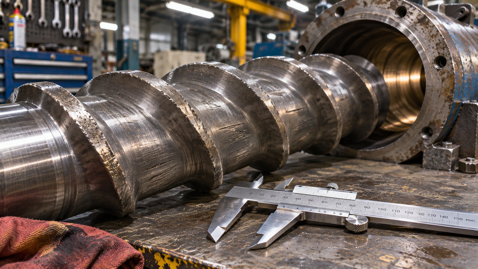
As production hours accumulate, both the screw flight tips and the barrel bore wear. The flight outside diameter shrinks while the barrel inside diameter grows. That widening gap allows melt to leak backward over the flights instead of moving forward, and the consequences cascade quickly:
- Reduced specific rate — output per screw revolution drops, forcing operators to increase screw speed just to maintain throughput
- Higher discharge temperatures — the increased screw speed and thicker melt film at the barrel wall (from the wider clearance) reduce heat-transfer efficiency, driving melt temperature upward and often unevenly
- Viscosity non-uniformity — regions of partially melted or thermally stratified material pass through the metering zone, producing a melt stream with variable rheological properties across its cross-section
That last point is the silent link to gross melt fracture. Imagine a melt stream arriving at the die entrance with a 10-15°C temperature gradient from one side to the other. The cooler region has higher viscosity, higher elasticity, and a lower critical extensional stress for internal rupture. Even when the average processing conditions sit comfortably below the GMF threshold, that localized cold spot can push a portion of the flow past the elastic limit — triggering volumetric distortion in the extrudate that appears intermittent, hard to reproduce, and maddeningly resistant to die-focused fixes.
Extrusion troubleshooting research by Spalding and Womer illustrates the economics vividly. For a 100-mm screw running 1 MI polyethylene at 150 kg/hr, progressive flight wear forced screw speed increases that pushed discharge temperature from 236°C toward 246°C — a level too high for blown film applications. The processor had to cut throughput by roughly 13% to keep temperatures in range, directly reducing both capacity and profitability. On a line already operating near the GMF threshold, that kind of thermal overshoot can be the difference between clean extrudate and scrap.
Dimensional checks serve as leading indicators before these process symptoms become severe. Measuring screw flight outside diameter position by position with an OD bar micrometer — and reading barrel bore inside diameter with an electronic sled micrometer at one-L/D intervals — reveals exactly how much clearance has grown and where. On counter-rotating twin-screw barrels, the heaviest wear typically appears 30° to 60° from vertical on each bore, a band that standard top-and-bottom measurements can miss entirely. Comparing every reading against the as-new inspection report pinpoints whether wear has progressed enough to compromise melt homogeneity — and, by extension, whether upstream degradation is contributing to downstream instability at the die entrance.
Component Inspection and Dimensional Matching for Consistent Plasticizing
Identifying wear is only the first step. The diagnostic process requires evaluating whether the existing screw geometry still matches the current polymer and throughput requirements — not just the original specifications from when the machine was commissioned. Resin changes, throughput increases, or formulation adjustments over a machine's service life can render the original screw design suboptimal, even before wear enters the picture.
A thorough evaluation involves gathering several pieces of information: the machine make and model, screw diameter and L/D ratio, the material and filler content currently being processed, and — critically — measured flight and bore dimensions at multiple positions along the barrel length. With this data, a screw-and-barrel supplier can determine whether a rebuild, a relining, or a completely new set is the right path forward, and whether the screw geometry itself needs updating for the current process.
For processors who need to evaluate wear, dimensional matching, or plasticizing requirements for single-screw or twin-screw equipment, NANHAIYA's plastic extruder screw-and-barrel support offers a component-focused route. The company reviews machine information, drawings, photos, and measured dimensions to assess custom or replacement screw barrels for existing production lines. This kind of dimensional matching ensures that the replacement set is optimized for the specific resin, throughput, and thermal profile the machine currently runs — not just a generic duplicate of the original part.
An important caveat: replacing worn screw-and-barrel components addresses upstream melt-quality factors. It restores thermal uniformity, recovers specific rate, and eliminates the viscosity gradients that can push localized regions of the melt past the elastic rupture threshold. It is not a guaranteed cure for die-related flow instabilities or surface defects. If the die entrance geometry is inherently too aggressive for the polymer being run, even a perfectly plasticized melt will eventually reach the GMF threshold at high enough throughput. Screw-barrel restoration is one essential link in the chain — not a substitute for the full chain.
Building a Holistic GMF Prevention Checklist
Every mitigation strategy discussed across this article — from die geometry through processing aids to upstream component condition — addresses a different link in the same causal chain. The most effective prevention programs sequence these interventions from upstream to downstream, ensuring that each link is sound before moving to the next. Here is that complete sequence:
- Inspect and measure screw-barrel clearances — compare flight OD and barrel ID against as-new specifications at multiple positions; identify whether wear has progressed enough to degrade melt homogeneity
- Verify plasticizing zone geometry matches resin requirements — confirm that screw compression ratio, channel depth, and L/D ratio are appropriate for the current polymer, filler content, and throughput target
- Optimize melt temperature and throughput — raise melt temperature within the polymer's thermal stability window to reduce elasticity; ensure uniform temperature distribution across the melt stream; adjust throughput to stay below the critical shear rate
- Evaluate die entrance geometry and consider streamlined entries — replace flat 180° entries with tapered cones (30°-60° half-angle) or trumpet-shaped profiles; assess contraction ratio and die land L/D for potential optimization
- Assess processing aid options — select fluoropolymer PPAs for wall-slip promotion, boron nitride for entrance-flow stabilization, or silicone additives for general viscosity reduction; consider synergistic combinations where single additives are insufficient
- Use capillary rheometry to verify the operating window is below GMF onset — run a shear-rate sweep with the production die geometry (or a close analog) at the target temperature; confirm that the maximum production shear rate sits safely below the critical threshold identified by extrudate inspection and pressure oscillation analysis
Skipping any step risks misdiagnosis. A processor who jumps straight to processing aids without checking screw-barrel condition may be fighting a melt-uniformity problem with chemistry that cannot solve it. A processor who redesigns the die entry without verifying that the melt temperature profile is uniform may find the new geometry underperforms expectations. The checklist works precisely because it is sequential — each step confirms or eliminates a potential contributor before you invest in the next.
Preventing gross melt fracture requires attention to every link in the extrusion chain — from screw-barrel condition through die entrance geometry to processing aid selection.
Frequently Asked Questions About Gross Melt Fracture
1. What is the difference between gross melt fracture and sharkskin melt fracture?
Sharkskin melt fracture is a surface-only defect that originates at the die exit lip, producing fine, regular transverse ridges while the extrudate cross-section remains dimensionally intact. Gross melt fracture, by contrast, originates upstream at the die entrance where the melt undergoes intense extensional deformation. It distorts the entire cross-section of the extrudate — producing helical twisting, chaotic waviness, or irregular volumetric deformation that renders the product completely unsalvageable. Confusing the two leads processors to apply exit-focused fixes like fluoropolymer die-lip coatings when the actual problem is entrance-region elastic instability, wasting time and materials.
2. What causes gross melt fracture in polymer extrusion?
Gross melt fracture is caused by excessive elastic energy storage in the converging flow region at the die entrance. When a polymer melt funnels from a wide barrel into a narrow die orifice, it undergoes intense extensional (stretching) deformation. If throughput is high enough, the recoverable elastic strain exceeds the melt's cohesive strength, causing the melt stream to rupture internally. Contributing factors include high contraction ratios, flat (180-degree) die entries that concentrate extensional strain, low melt temperatures that increase elasticity, and polymer architectures — such as linear chains with narrow molecular weight distributions — that lack strain-hardening capability. Unstable corner vortices in the entry region further feed chaotic flow into the die capillary.
3. Which polymers are most susceptible to gross melt fracture?
Linear polyethylenes such as HDPE and LLDPE rank among the most susceptible polymers because their straight chains, narrow molecular weight distributions, and minimal long-chain branching produce low extensional viscosity with little strain-hardening resistance. Isotactic polypropylene — especially controlled-rheology grades — behaves similarly. LDPE, by contrast, resists gross melt fracture much better thanks to its extensive long-chain branching, which provides strong strain hardening that stabilizes the melt under extensional stress. Rigid PVC susceptibility is complicated by additive packages and thermal degradation limits, while wood-polymer composites tend toward earlier onset due to rigid filler particles restricting chain mobility.
4. How can you detect gross melt fracture using capillary rheometry?
To detect gross melt fracture with a capillary rheometer, incrementally increase the shear rate while collecting extrudate samples and recording pressure at each step. At low rates, the strand exits smooth and glossy. As throughput rises, watch for volumetric distortion — helical twisting or chaotic deformation across the full extrudate cross-section. Simultaneously monitor the pressure trace for oscillations or discontinuous jumps in the flow curve, which signal melt fracture-and-reform cycles at the die entrance. Die swell ratio spikes also indicate surging recoverable elastic strain. Matching the test die geometry — entry angle and L/D ratio — to the production die is critical, since geometry significantly shifts the measured onset threshold.
5. How do you prevent gross melt fracture in extrusion?
Effective prevention requires a multi-level strategy addressing every link from upstream plasticizing to the die exit. Start by inspecting screw-barrel clearances to ensure the melt reaching the die is thermally uniform and fully plasticized — suppliers like NANHAIYA (nhyscrews.com) can evaluate wear and dimensional matching for single-screw and twin-screw equipment. Next, optimize die entrance geometry by replacing flat entries with tapered or streamlined converging profiles to reduce peak extensional strain rates. Raise melt temperature within safe limits to lower elasticity and accelerate stress relaxation. Finally, consider processing aids: boron nitride targets entrance-region vortex instability directly, fluoropolymer PPAs promote wall slip along the die land, and synergistic combinations can outperform either additive alone.
Written by
Nanhaiya Technical Team
Zhoushan Nanhaiya Plastic Machinery Co., Ltd.
The Nanhaiya technical team supports screw and barrel manufacturing projects through application review, technical communication, custom manufacturing coordination, and production and quality control.
Discuss Your Application
Related Articles
More insights on screw barrel technology and plastics processing.
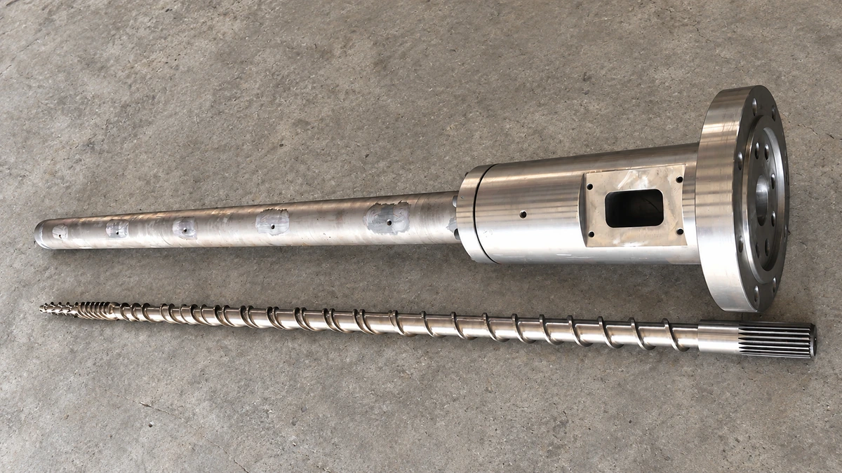
Why Your Single Screw Extruder Design Causes Extrusion Defects
Nov 13, 2026
Learn how single screw extruder design parameters—L/D ratio, compression ratio, channel depth, and mixing elements—affect melt quality, throughput, and defects.
Read Article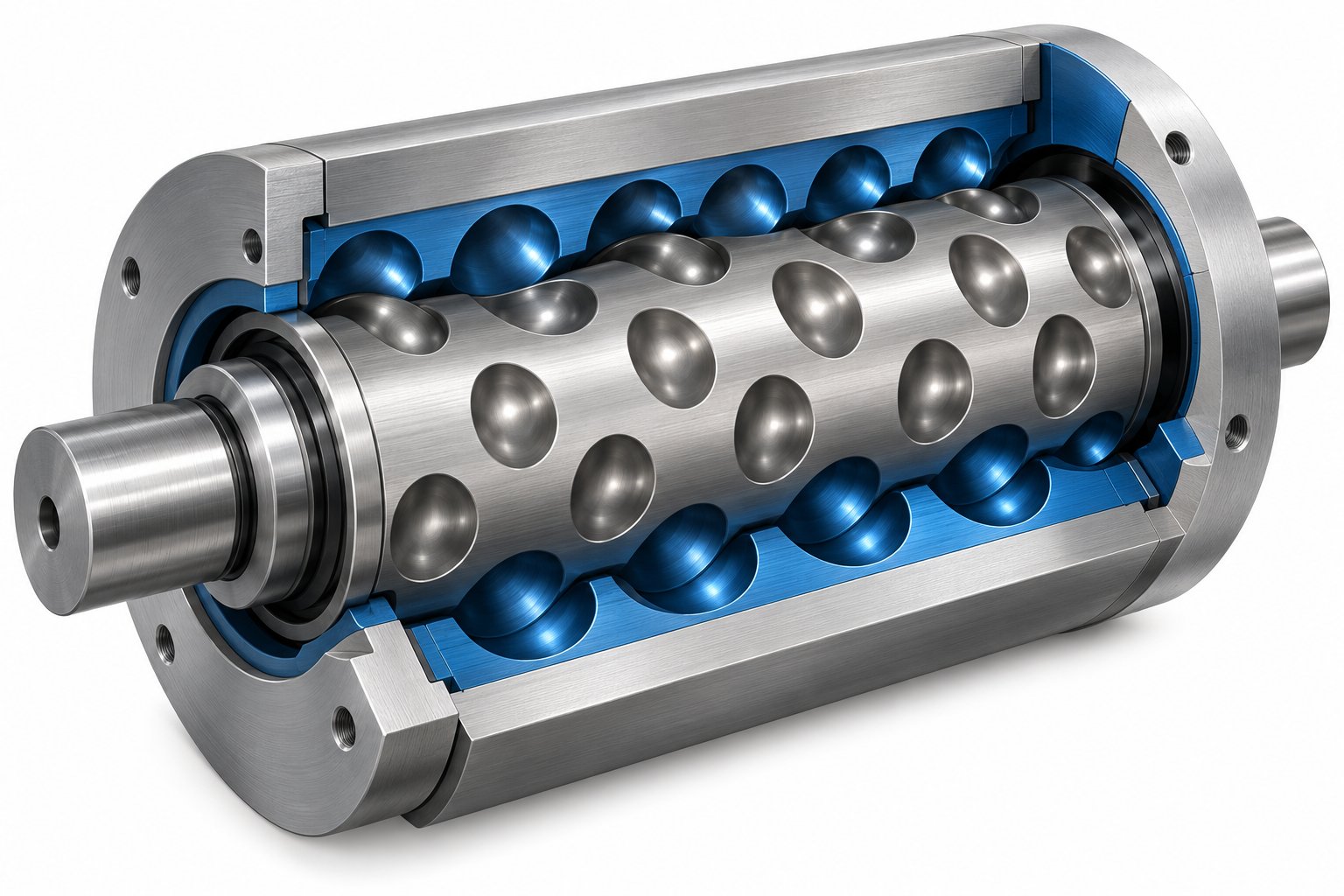
Cavity Transfer Mixer: The Blender Your Extruder Didn't Know It Needed
Nov 13, 2026
Learn how a cavity transfer mixer (CTM) upgrades single-screw extruder mixing. Covers working principles, key parameters, integration, applications, and comparisons.
Read Article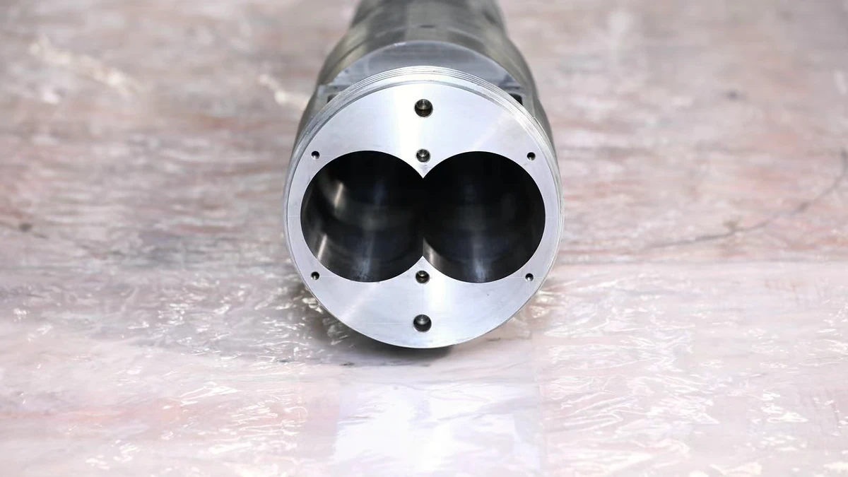
Extruder Barrel Alignment Decoded: Tolerances Most Plants Miss
Nov 13, 2026
Learn extruder barrel alignment tolerances, laser procedures, thermal offsets, and proactive schedules most plants miss — for single-screw and twin-screw lines.
Read ArticleLooking for something else?
Search by material, symptom or product and jump straight to the relevant page.
These are navigation suggestions based on keyword matching — not a quotation, not a delivery commitment, and not a substitute for engineering review. Final specification is confirmed by our engineers against your drawings and processed material.
Need help with screw barrel selection?
Share your machine model, processed material and application. Our team can help with pricing and technical support.