

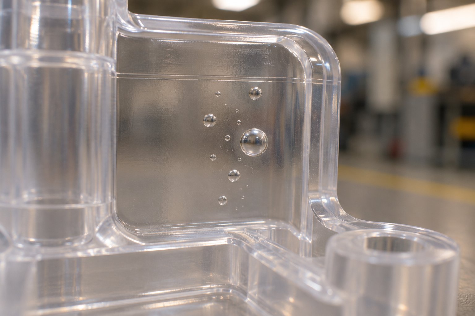
What Injection Molding Bubbles Are and Why They Matter
Injection molding bubbles are trapped pockets of gas or vapor that form inside or on the surface of a molded plastic part. They can appear as small spherical hollows visible through a transparent component, or they can lurk invisibly deep within an opaque housing, only discovered when the part cracks under load or fails a cross-section inspection. Regardless of where they hide, these defects weaken mechanical strength, distort dimensional accuracy, compromise surface aesthetics, and — in clear materials — destroy optical clarity.
So why do so many molders struggle to eliminate them? The answer is surprisingly simple: they treat every bubble the same way.
Defining the Bubble Defect in Molded Parts
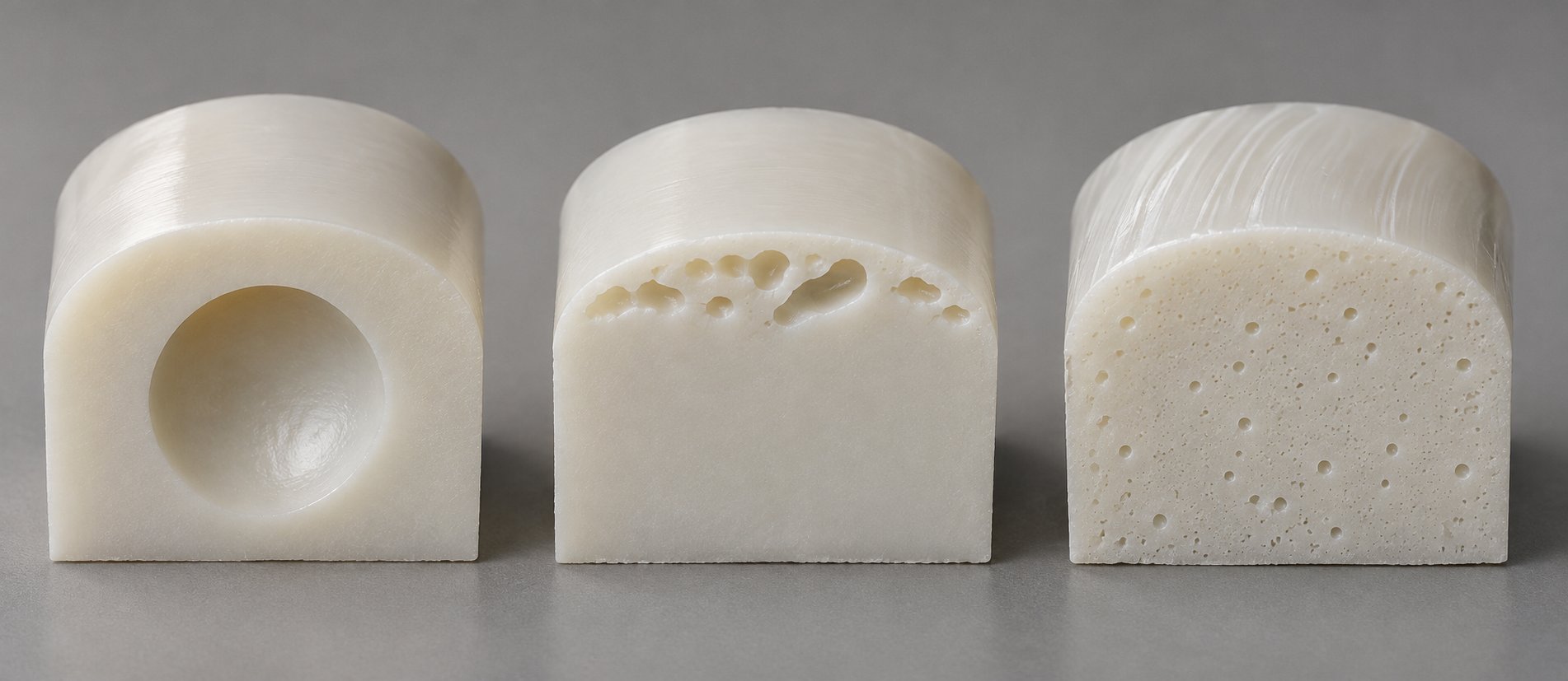
A bubble defect in injection molding falls into one of three fundamentally different categories. Vacuum voids form when thick sections of a part shrink inward during cooling, pulling the still-soft core away from the solidified outer skin and leaving a hollow cavity. Trapped-gas bubbles occur when air is physically locked inside the mold cavity during injection, or when thermal degradation of the resin generates volatile gases that cannot escape. Moisture-driven bubbles appear when water absorbed by hygroscopic resins flashes into steam at processing temperatures, creating vapor pockets throughout the part. Each type looks different under magnification, responds differently to diagnostic tests, and — critically — requires a completely different corrective strategy.
Why Diagnosis Must Come Before Correction
Most troubleshooting guides hand you a flat list of causes and fixes: increase pack pressure, check your vents, dry your material. That approach works only if you happen to guess the right cause on the first try. In reality, air bubbles in injection molding share overlapping visual symptoms. A molder who raises pack pressure to eliminate what looks like a void may be chasing a moisture bubble that no amount of packing will solve. Worse, the higher pressure can introduce flash at the parting line or increase residual stress — trading one defect for another.
Applying the wrong fix to the wrong bubble type wastes cycles and can introduce new defects.
This article follows a diagnostic-first structure. You'll learn to identify the bubble type before reaching for any process adjustments, then follow a prioritized troubleshooting sequence that experienced molding engineers actually use on the production floor — low-cost, high-probability checks first, hardware and tooling modifications last.
Transparent vs Opaque Parts and Bubble Severity
Imagine two parts molded from the same resin with the same internal void. One is a clear polycarbonate lens; the other is a black-pigmented structural bracket. The lens fails cosmetic inspection immediately — bubbles scatter light, reduce transmission, and create visible distortion that no customer will accept. Transparent parts face stricter optical-clarity requirements where even microscopic inclusions can trigger rejection, a reality well-documented in clear plastic molding applications where defects invisible on opaque components become immediate quality concerns.
The bracket, on the other hand, might pass a visual check without issue. Yet that hidden void reduces the load-bearing cross-section and creates an internal stress-concentration point. Under cyclic loading or impact, the part fails prematurely — and the root cause is only discovered after a costly field return. Bubbles in injection molding are never harmless; they are simply harder to detect in opaque materials.
Understanding how bubble type, resin family, and part transparency interact is the foundation of effective troubleshooting. The sections ahead break down each of those variables in detail, starting with the three bubble types and the simple diagnostic test that tells them apart.
Three Bubble Types Every Molder Must Distinguish
Every bubble trapped in a molded part started somewhere — but not every bubble started the same way. That distinction matters more than most molders realize. A single, centered void in a thick boss and a cluster of small blisters near a flow junction may both look like "bubbles," yet they arise from entirely different physical mechanisms and demand opposite corrective actions. Lump them together, and you'll waste hours adjusting parameters that have no bearing on the actual root cause.
The three categories below represent the only root mechanisms that produce bubbles in injection molding. Every defect you encounter on the production floor traces back to one of them.
Vacuum Voids and Shrinkage Mechanics
Picture a thick cross-section cooling inside the mold. The outer skin solidifies first because it contacts the cooler mold steel directly. As the interior polymer continues to cool, it contracts — and since molten plastic occupies more volume than solidified plastic, that contraction creates a negative pressure zone deep inside the wall. If pack pressure cannot force additional melt into the shrinking core before the gate freezes off, the still-soft center literally tears away from itself, leaving a hollow cavity with no gas inside at all.
This is a vacuum void, and it shares the exact same root cause as a sink mark. The only difference is skin stiffness. A thin, flexible skin deflects inward and produces a visible surface depression — the classic sink. A thicker or more rigid skin holds its shape, forcing the shrinkage to manifest internally as a void instead. Parts thicker than about 6 mm are especially susceptible, and the void almost always appears at the geometric center of the thickest region, often as a single, roughly spherical cavity.
The materials-science principle behind this is straightforward: volumetric shrinkage in semicrystalline resins like polypropylene or nylon can reach 1.5 to 3 percent, and in thick sections, the outer shell locks in place long before the core finishes contracting. Without adequate pack pressure to compensate, a void is inevitable.
Trapped Gas and Degradation Off-Gassing
Trapped-gas bubbles are the opposite of vacuum voids — they contain real gas under pressure. The gas can come from several sources, and identifying which one matters for the fix:
- Air entrapment during fill. When converging flow fronts meet, when melt jets across a cavity instead of advancing as a uniform front, or when air in ribs and projections off the nominal wall has no escape path, pockets of air become sealed inside the part. These bubbles tend to appear at flow-front junctions, at the ends of fill, or trailing behind non-vented features.
- Poor or blocked venting. Even a well-designed flow pattern will trap air if the mold's vents are too shallow, too short, or clogged with residue. The air that should exit at the last-fill locations stays put and gets compressed into the melt.
- Thermal degradation and off-gassing. When resin sits at elevated temperatures too long — due to excessive residence time, overheated barrel zones, or a shear-intensive screw design — polymer chains break down. That decomposition releases volatile gases directly into the melt stream. Additives, colorant carriers, and lubricants can do the same if pushed beyond their thermal stability window.
A key principle from polymer processing science explains why these gases form discrete bubbles rather than dissolving harmlessly: gas solubility in a polymer melt is pressure-dependent. At the high pressures inside the barrel and during injection, gases remain dissolved. As pressure drops — during mold filling, at flow-front tips, or during cooling — solubility decreases and the gas nucleates into visible bubbles. Think of it like opening a carbonated drink: the pressure drop releases dissolved CO2 as fizz. The same physics governs bubbles in plastic injection molding.
Unlike vacuum voids, gas bubbles often appear in multiples, cluster at junctions or last-fill regions, and may show irregular shapes distorted by the flow pattern. A venturi effect at ribs, ejector pins, or a misaligned nozzle tip can even suck air into the melt stream — a less obvious source that only surfaces after more common causes have been ruled out.
Moisture Bubbles in Hygroscopic Resins
Moisture bubbles are technically a subset of gas bubbles — the gas is steam — but they deserve their own category because the fix is entirely upstream of the molding process. Hygroscopic resins like nylon (PA), polycarbonate (PC), ABS, PET, and PMMA absorb water from ambient air during storage and handling. When that moisture-laden resin enters the barrel, temperatures well above 100 °C cause the absorbed water to flash into vapor. The resulting steam pockets get carried forward with the melt and freeze into the part as bubbles.
What makes moisture bubbles distinctive is their pattern. They often produce a characteristic splay or silver-streak appearance on the surface — fine, elongated streaks radiating from the gate — alongside internal bubbles scattered more randomly through the part. The defect tends to be worst on the first few shots after a machine sits idle, when condensation has had time to accumulate on the resin pellets in the feed throat or hopper.
The critical point is this: no amount of process adjustment — not higher pack pressure, not slower injection speed, not better venting — will eliminate moisture bubbles. The water must be removed before it ever reaches the barrel. Proper drying to a material-specific temperature, time, and dew-point target is the only effective corrective action. Skipping this step, or relying on a dryer that isn't reaching its target dew point, is one of the most common reasons injection molding air bubbles persist despite repeated process changes.
The Heat-Gun Diagnostic Test Explained
Here is the practical question every molder faces: you're holding a part with a visible bubble, and you need to know which of the three types you're dealing with before making any changes. The heat-gun test gives you that answer in under 15 minutes.
The procedure is simple but requires patience and a few conditions for reliable results:
- Cross-section the part. Cut through the area containing the bubble so you can observe it directly. If the bubble is near the surface, you may be able to test without sectioning, but a clean cross-section under a stereo microscope or magnifying loupe gives the clearest view.
- Use a freshly molded part. Test the part within roughly four hours of molding. Over time, air can migrate through the polymer wall and infiltrate a vacuum void, converting it into what appears to be a gas bubble. As injection molding expert John Bozzelli has demonstrated, a part tested 16 hours after molding can give the opposite response from the same part tested fresh — a striking reminder that timing matters.
- Apply gentle, localized heat. Use a heat gun — not a torch — and warm the area surrounding the bubble until the polymer just begins to soften. Plastics are poor thermal conductors, so be patient and avoid scorching the surface.
- Observe the bubble's response. This is where the diagnosis happens. A vacuum void collapses inward — the softened skin can no longer resist atmospheric pressure, so it pushes down into the empty cavity, producing a visible depression or sink. A gas or moisture bubble expands outward — the trapped gas heats up, its pressure rises, and it pushes against the softened polymer, inflating the surface and sometimes popping through entirely.
That single observation splits your troubleshooting into two completely different paths. A collapsing void sends you toward pack pressure, hold time, gate sizing, and wall-thickness optimization. An expanding bubble sends you toward material drying, vent inspection, injection-speed profiling, and screw decompression settings.
| Bubble Type | Root Mechanism | Visual Appearance | Heat-Gun Response | Primary Fix Category |
|---|---|---|---|---|
| Vacuum Void | Volumetric shrinkage in thick sections creates negative internal pressure; the core pulls away from the solidified skin | Single, roughly spherical cavity centered in the thickest wall; often invisible from the surface in opaque parts | Collapses inward — surface sinks as atmospheric pressure pushes into the void | Packing and hold optimization, gate sizing, wall-thickness redesign |
| Trapped Gas | Air entrapment during fill, poor venting, or volatile off-gases from thermal degradation of resin or additives | Multiple bubbles at flow junctions, last-fill areas, or near non-vented features; may show irregular or elongated shapes | Expands outward — gas pressure inflates softened wall; may pop through the surface | Venting improvements, injection-speed profiling, back-pressure adjustment, screw and barrel condition check |
| Moisture Bubble | Absorbed water in hygroscopic resin flashes to steam at barrel temperatures above 100 °C | Splay or silver streaks on the surface with scattered internal bubbles; worst on first shots after idle time | Expands outward — steam pressure pushes against softened polymer | Material drying to correct temperature, time, and dew-point targets; hopper and dryer verification |
Keep this table within reach the next time you encounter bubbles in injection molding. It condenses the diagnostic logic into a single reference and prevents the most common mistake in bubble troubleshooting — applying a packing fix to a gas problem, or chasing vent blockages when the real culprit is undried resin sitting in the hopper.
Of course, knowing the bubble type is only the starting point. The resin you're running changes the probability of each type dramatically — and that material-specific dimension is where the troubleshooting path sharpens next.
Material-Specific Bubble Tendencies by Resin Family
The resin sitting in your hopper determines which bubble type you're most likely to encounter — and that single variable can redirect your entire troubleshooting strategy. A molder running polycarbonate who skips the dryer checkout is almost guaranteed to chase an injection molding bubble defect that no process tweak will solve. A molder running polypropylene who obsesses over drying parameters is wasting time on a cause that barely exists for that material. Grouping resins by their moisture behavior is the fastest way to narrow the field before touching a single machine setting.
Hygroscopic Resins and Moisture-Driven Bubbles
Hygroscopic plastics absorb water directly into their polymer chains — not just on the surface, but deep within the molecular structure. That absorbed moisture cannot be removed by blowing ambient air across the pellets. It requires controlled drying at specific temperatures and dew points, typically using a desiccant dryer capable of delivering air at -40 °C dew point or lower.
When you're figuring out how to avoid air bubbles in injection molding with these materials, moisture control is always step one. Consider how differently each resin responds:
- Nylon (PA) is extremely hygroscopic, absorbing up to 8% of its weight in water depending on the grade and storage conditions. Underdried nylon produces classic splay — silver streaks radiating from the gate — alongside internal moisture bubbles scattered throughout the part. Target moisture content must drop below 0.1% before processing.
- Polycarbonate (PC) is particularly dangerous because it does not just form bubbles when wet — it undergoes hydrolytic degradation at processing temperatures. Moisture breaks the polymer chains themselves, permanently reducing molecular weight, impact strength, and transparency. You cannot recover a hydrolyzed PC part by adjusting pack pressure. The damage is chemical and irreversible.
- ABS, PET, and PMMA all require thorough drying to prevent surface defects and internal voids. PET is especially sensitive — residual moisture triggers hydrolysis that degrades intrinsic viscosity, affecting both bubble formation and long-term mechanical performance.
The common thread across all hygroscopic resins is this: if your dryer is not hitting its target dew point, or if the material spends too long exposed to ambient air between the dryer and the feed throat, you'll be fighting moisture bubbles no matter how perfectly you've dialed in everything else.
Non-Hygroscopic Resins and Trapped-Air Risks
Polyethylene, polypropylene, and polystyrene do not absorb moisture into their molecular structure. Any water present sits on the pellet surface and evaporates easily, even with minimal heating. For these materials, moisture-driven bubble defects are rare — and that immediately shifts the diagnostic focus.
When bubbles appear in a PP or PE part, you're almost certainly dealing with either a vacuum void in a thick section or trapped air from inadequate venting. The troubleshooting path skips the dryer entirely and moves straight to pack pressure, gate freeze-off timing, vent condition, and injection-speed profiling. This distinction alone can save hours of misdirected effort.
That said, non-hygroscopic resins stored in humid warehouses or exposed to condensation during cold-weather shipping can carry enough surface moisture to cause sporadic issues. It's uncommon, but don't rule it out if you've exhausted every other variable.
Colorants, Additives, and Regrind as Volatile Sources
Even after you've matched your drying protocol to the base resin, secondary materials can reintroduce volatile compounds that nucleate bubbles. Understanding how to get rid of bubbles in injection molding means accounting for everything entering the barrel — not just the virgin pellets.
- Pigment carriers and colorant concentrates often use low-molecular-weight waxes or oils as dispersing agents. These carriers can outgas at elevated melt temperatures, generating volatile compounds that form small, scattered bubbles. The risk rises with higher processing temperatures and longer residence times.
- Regrind material introduces two hazards. First, regrind from hygroscopic resins may have re-absorbed moisture during storage after granulation. Second, previously processed material already carries some degree of thermal history — degradation byproducts accumulated during its first pass through the barrel can release additional gas on reprocessing.
- Blowing-agent contamination is a less obvious but very real production concern. Shared equipment that previously ran foam-grade resin containing chemical blowing agents can retain trace residues in dead spots, on screw flights, or in the check-ring assembly. Those residues activate in subsequent runs, producing unexpected foaming and bubble defects in parts that should be solid.
A disciplined approach treats every material input — virgin resin, masterbatch, regrind, and even purge compound residues — as a potential volatile source until proven otherwise.
| Resin | Hygroscopic? | Recommended Drying Temp | Drying Time | Primary Bubble Risk | Key Precaution |
|---|---|---|---|---|---|
| Nylon (PA) | Yes | 80 - 85 °C | 4 - 6 hours | Moisture bubbles and splay | Dry to below 0.1% moisture; use desiccant dryer with -40 °C dew point |
| Polycarbonate (PC) | Yes | 120 °C | 3 - 4 hours | Moisture bubbles and hydrolytic degradation | Hydrolysis is irreversible; verify dew point before every run |
| ABS | Yes | 80 - 85 °C | 2 - 4 hours | Surface splay and gloss defects | Dry to below 0.1%; regrind absorbs moisture faster than virgin pellets |
| PET | Yes | 150 - 170 °C | 4 - 6 hours | Hydrolysis and viscosity loss | Monitor intrinsic viscosity; avoid hopper exposure to ambient air |
| PMMA (Acrylic) | Yes | 75 - 80 °C | 3 - 4 hours | Moisture bubbles visible in transparent parts | Even small bubbles destroy optical clarity; strict drying is essential |
| Polyethylene (PE) | No | Not typically required | N/A | Vacuum voids in thick sections; trapped air | Focus on venting and pack pressure; check for surface condensation in cold climates |
| Polypropylene (PP) | No | Not typically required | N/A | Vacuum voids in thick sections; trapped air | High volumetric shrinkage increases void risk in thick walls; optimize gate and pack |
| Polystyrene (PS) | No | Not typically required | N/A | Trapped air at flow junctions | Verify vent condition; watch for degradation off-gassing at high melt temps |
Matching the resin family to its dominant bubble risk is a powerful filter — it eliminates entire categories of root causes before you ever open the machine controller. Yet material is only half of the equation. The process parameters you choose interact with that material's behavior in ways that can either suppress bubbles or amplify them, and those trade-offs are where most troubleshooting gets complicated.

Process Parameter Adjustments and Critical Trade-Offs
Knowing your resin and confirming the bubble type through diagnosis puts you in a strong position — but sooner or later, you'll need to reach for the machine controller. This is where what causes bubbles in injection molding gets tangled up with what causes flash, short shots, and degradation. Every parameter adjustment that suppresses one defect has the potential to trigger another if you push it too far or apply it to the wrong bubble type.
Four process variables dominate bubble formation: melt temperature, injection speed, pack and hold pressure, and back pressure. Each one influences bubble behavior through a specific physical mechanism — and each one carries a trade-off that most troubleshooting guides never mention. Understanding those mechanisms and their limits is the difference between a targeted correction and a frustrating cycle of chasing new problems.
Melt Temperature and Thermal Degradation Balance
Raising melt temperature improves flow. The polymer becomes less viscous, fills thin sections more easily, and reaches distant cavity areas before it begins to solidify. For vacuum voids, this can help because better flow means the melt packs more effectively into thick sections before the gate freezes off. For trapped-air scenarios, improved flow sometimes allows the melt front to advance more uniformly, reducing the jetting and hesitation patterns that entrap air pockets.
The trade-off? Every resin has a thermal stability ceiling, and crossing it generates the very gas you're trying to eliminate. When polymer chains break down — a process called thermal degradation — they release volatile compounds directly into the melt. These gases nucleate into bubbles that no amount of venting or packing will remove because the gas source is the material itself. The diagnostic sign is telling: degradation-driven bubbles often appear near the gate where shear heating is highest, or they show up as a gradual worsening over consecutive shots as residence time accumulates.
A practical rule of thumb: if you need to raise melt temperature to improve fill, do so in 5 °C increments and monitor for color shift, brittleness, or a burning odor — all early indicators of thermal breakdown. Check your actual melt temperature with an air-shot pyrometer reading rather than trusting the barrel zone set points, since shear heating from the screw can push the real melt temperature 10 to 20 °C above what the controller displays. If bubbles increase as you raise temperature, you've likely crossed the degradation threshold and need to reverse direction.
Pack Pressure, Hold Time, and Void Elimination
Pack and hold pressure is the primary weapon against vacuum voids. The mechanism is direct: after the cavity fills, continued pressure forces additional melt through the gate and into the shrinking interior of thick sections. This compensates for volumetric contraction as the polymer cools, preventing the negative-pressure condition that creates a void. Extending hold time ensures that packing continues until the gate solidifies, maximizing the material delivered to areas that need it most.
Here's what many molders discover the hard way: increasing pack pressure high enough to eliminate a deep void in a thick boss often creates flash at the parting line or around ejector pins. The mold steel has a finite clamp-force capacity, and once cavity pressure exceeds the force keeping the mold halves together, plastic squeezes into every available gap. You end up trading an internal defect for an external one.
The smarter approach is incremental. Raise pack pressure in small steps — roughly 5 to 10 MPa at a time — while monitoring both cushion size stability and parting-line flash. If the cushion (the small pad of melt remaining in front of the screw at the end of the hold phase) bounces or fluctuates between shots, the check ring may not be sealing consistently, and pressure is bleeding backward instead of reaching the cavity. A stable cushion of 3 to 6 mm confirms that pressure is transmitting forward as intended.
For thick-walled parts, hold time matters as much as hold pressure magnitude. A gate that freezes off in two seconds cannot deliver packing for ten, no matter how high you set the pressure. If voids persist even at elevated pack levels, the gate may simply be too small — a mold-design issue that no process parameter can fully overcome.
Injection Speed, Back Pressure, and Gas Compression
Injection speed controls how the melt front advances through the cavity, and its effect on bubble formation depends entirely on the bubble type you're fighting.
When trapped-air bubbles are the problem, a fast injection speed can outrun the air's ability to escape through the vents. The melt front tumbles forward, folding over pockets of air and sealing them inside the part. Slowing the injection speed gives the air time to migrate ahead of the advancing front and exit through the vent channels. Multi-stage injection profiles — where speed drops in specific cavity regions identified as air-trap zones — offer precision without sacrificing cycle time across the entire fill phase.
The catch: slow the injection too much and you risk hesitation marks, incomplete fill, or cold flow lines where the melt front stalls and reheats poorly. In thin-walled parts, an overly cautious speed can cause short shots before the cavity even reaches its last-fill region. The goal isn't the slowest possible speed — it's the right speed for each zone of the cavity.
Back pressure operates earlier in the cycle, during plasticization. As the screw rotates and conveys resin forward, back pressure resists the screw's rearward movement, forcing the melt to compress more tightly in the metering zone. This compression dissolves entrained air into the melt — higher back pressure increases gas solubility and reduces bubble nucleation during injection. You'll also get better melt homogeneity, more consistent shot size, and improved color dispersion.
But excessive back pressure generates shear heat that raises the actual melt temperature beyond what the barrel heaters dictate. Push it too far and you cross into thermal degradation territory — the same problem you'd create by overheating the barrel zones. Back pressure settings typically start around 50 PSI (0.35 MPa) and increase in 10 PSI increments. Most resins perform well below 300 PSI; going higher risks shearing the polymer and producing the very off-gases you're trying to suppress. Reinforced resins with glass or carbon fiber demand particular caution, since excessive back pressure breaks fibers and degrades mechanical properties without solving the bubble problem.
Navigating Parameter Trade-Offs Without Creating New Defects
What causes bubbles in plastic injection molding is rarely a single parameter set wrong in isolation — it's usually an interaction between two or three variables. That's why experienced molders avoid making large, simultaneous changes. Adjust one parameter at a time, run enough shots to confirm the trend (typically 10 to 20 cycles to reach steady state), and document the result before moving to the next variable.
A few practical guidelines keep the trade-offs manageable:
- Verify cushion size after every pack-pressure change. An unstable or disappearing cushion means the machine isn't delivering the pressure you think it is.
- Use air-shot temperature readings whenever you adjust back pressure or screw speed. The displayed barrel set point can differ significantly from the actual melt temperature.
- Profile your injection speed in stages rather than using a single flat speed. Slow down at air-trap zones and last-fill areas, then speed up through long runners and thin sections where hesitation is the bigger risk.
- Never raise melt temperature and back pressure simultaneously. Both increase the thermal load on the resin. Change one, measure the effect, and then decide whether the second adjustment is still necessary.
The table below consolidates each parameter's mechanism, its target bubble type, and the trade-off you need to watch for. Treat it as a quick reference when you're standing at the press, but always filter it through the diagnostic logic from earlier — a parameter fix aimed at the wrong bubble type won't help and may hurt.
| Parameter | Adjustment Direction | Mechanism | Bubble Type Addressed | Potential Trade-Off |
|---|---|---|---|---|
| Melt Temperature | Increase moderately (5 °C steps) | Reduces viscosity, improves fill and packing reach into thick sections | Vacuum voids, some trapped-air scenarios | Exceeding thermal stability generates degradation gases; risk of new gas bubbles, discoloration, and brittleness |
| Pack / Hold Pressure | Increase incrementally (5 - 10 MPa steps) | Forces additional melt into shrinking core of thick sections, compensating for volumetric contraction | Vacuum voids | Flash at parting line and ejector pins; increased residual stress; potential warpage on ejection |
| Hold Time | Extend until gate freeze-off | Maintains packing pressure longer, delivering more material before the gate solidifies | Vacuum voids in thick-walled parts | Longer cycle time; overpacking thin areas if gate sizing is not matched |
| Injection Speed | Reduce or use multi-stage profile | Slows melt-front advancement, allowing air to escape through vents ahead of the flow front | Trapped-gas bubbles | Hesitation marks, short shots, or cold-flow lines in thin sections; longer fill time |
| Back Pressure | Increase in 10 PSI increments | Compresses gas entrained during plasticization, increasing gas solubility in the melt and improving homogeneity | Trapped-gas bubbles, air entrapment during screw recovery | Excessive shear heat raises actual melt temperature; fiber breakage in reinforced resins; accelerated screw and barrel wear |
Notice that every row in this table targets a specific bubble type — not "bubbles" in general. A molder fighting vacuum voids focuses on pack pressure and hold time. A molder dealing with trapped gas focuses on injection speed and back pressure. Mixing those strategies without confirming the defect type first is exactly how a bubble in injection molding survives round after round of process tweaks that never quite solve it.
Process parameters, however, can only compensate so far. There are limits built into the tooling itself — gate location, gate size, vent depth, and wall-thickness transitions — that determine whether the process window is wide enough to eliminate bubbles or so narrow that even perfect settings can't fully compensate. Those mold-design factors set the ceiling on what process adjustments alone can achieve.
Mold Design Factors That Cause and Prevent Bubbles
A perfectly dialed-in process cannot overcome a mold that fights it at every turn. Gate placement decides whether pack pressure ever reaches the thick section that needs it. Vent dimensions determine whether trapped air has a path out or stays locked inside the part. Wall-thickness transitions control how uniformly the melt cools and shrinks. When any of these tooling variables falls outside the workable range, even the best parameter settings leave an air bubble in injection molding that stubbornly refuses to go away.
Mold design is the variable most often overlooked in bubble troubleshooting — partly because changing steel is expensive and slow, and partly because process tweaks feel more accessible. Yet understanding these design factors helps you recognize when you've hit the ceiling of what process adjustments alone can fix, and it gives you the engineering language to request the right tooling modification instead of guessing.
Gate Location, Size, and Freeze-Off Timing
Imagine a part with a thick boss at the far end of the cavity, gated at the opposite wall. The melt must travel the entire length of the part, losing heat along the way, before it reaches the section that demands the most packing. By the time the flow front arrives at that boss, the material is already partially cooled and more viscous. Worse, the gate — sitting far upstream — freezes off early, cutting the supply line before pack pressure has had enough time to force additional material into the shrinking core of the thick region. The result is a vacuum void buried inside the boss, invisible from the surface but structurally significant.
Gate location, in other words, controls the reach of your packing phase. Positioning the gate at or near the thickest section ensures the hottest, most packable melt arrives where volumetric shrinkage is greatest, and it keeps the gate open longest in the zone that needs continued pressure. When that's not feasible — because of cosmetic requirements, ejection constraints, or multi-cavity layouts — a secondary gate or a hot-runner valve gate that feeds the thick area directly can close the gap.
Gate sizing matters just as much. An undersized gate restricts flow during fill and, more critically, freezes off prematurely during the hold phase. Once the gate solidifies, no further melt can enter the cavity regardless of how high you set the pack pressure on the controller. You'll see this as voids in thick sections that refuse to shrink no matter how aggressively you pack — a classic sign that the limitation is in the steel, not the settings. Increasing gate cross-section even modestly can extend the effective hold window by several seconds, providing the packing duration thick walls require.
Runner design plays a supporting role here as well. Unbalanced runners in a multi-cavity tool deliver unequal pressure to each cavity, meaning some parts pack fully while others starve. Cold slugs — solidified material plugs that form in the runner between shots — can intermittently block gates, causing sporadic bubble defects that appear in random cavities and frustrate any systematic troubleshooting effort. Regular cold-slug well maintenance and balanced runner geometry eliminate these inconsistencies before they disguise themselves as process problems.
Venting Depth, Placement, and Maintenance
Every cubic centimeter of air inside the mold cavity at the start of injection must go somewhere. If the venting system provides a clear exit path, that air escapes ahead of the advancing melt front. If it doesn't, the air gets compressed into the part — forming surface or near-surface gas bubbles that no amount of speed reduction will fully eliminate.
Effective venting depends on three dimensions working together:
- Vent depth must be shallow enough to prevent plastic from entering (typically 0.025 to 0.05 mm for most commodity resins) yet deep enough to allow air to pass freely. A vent that's too shallow for the resin's viscosity acts like a sealed wall, and a vent that's too deep produces flash along the parting line.
- Vent land length — the narrow channel before the vent opens into the wider relief — should be kept short, generally 1 to 3 mm. A long, narrow land creates backpressure that slows air evacuation, effectively throttling the vent's capacity right when fast air displacement matters most.
- Vent placement targets the last-fill locations in the cavity. Air migrates ahead of the melt front, so it accumulates wherever the flow front converges or terminates. Ribs, bosses, corners opposite the gate, and areas surrounded by converging flow fronts all need dedicated vents. Missing vents in deep sections or slider areas are one of the most common mold-related causes of trapped-gas bubble defects in injection molding.
Here's the detail many molders overlook: even a well-designed vent degrades over time. Residue from outgassing additives, mold-release agents, and microscopic flash gradually narrows the vent channel. A vent that measured 0.04 mm on day one may effectively be 0.01 mm after a few thousand cycles — barely functional. Scheduled vent cleaning during preventive maintenance is one of the simplest and cheapest ways to prevent recurring air bubble defects in injection molding, yet it's one of the most frequently skipped steps.
Wall Thickness Transitions, Ribs, and Boss Geometry
Part geometry creates the thermal landscape that dictates where voids form. Thick sections cool slowly at the center; thin sections solidify quickly from both sides. Where these two meet, the differential cooling rate produces localized shrinkage imbalances — and those imbalances are where bubble injection molding problems take root.
A few geometry patterns are repeat offenders:
- Thick-to-thin wall transitions. An abrupt step from a 4 mm wall to a 1.5 mm wall creates a thermal bottleneck. The thin section freezes off quickly and stops transmitting pack pressure to the thick area behind it, leaving the thick zone to shrink freely and form voids. Gradual transitions using chamfers or fillets — with the adjacent wall no thinner than 40 to 60 percent of the primary wall — smooth the cooling gradient and maintain packing flow.
- Boss designs with excessive base thickness. A mounting boss that blends into the nominal wall with a thick root section accumulates mass at the junction. That mass cools far slower than the surrounding wall, forming a void at the base even when the rest of the part is defect-free. Coring out the boss interior and keeping the wall thickness at the base consistent with the nominal wall reduces the thermal mass and eliminates the void.
- Rib intersections. Where two ribs meet — or where a rib meets a wall — material accumulates at the junction. The thicker the rib relative to the wall, the worse the problem. Industry guidelines recommend keeping rib thickness between 50 and 70 percent of the nominal wall, with rib height no more than three times the wall thickness. Exceeding these ratios doesn't just risk sink marks on the cosmetic side — it creates internal voids at the rib base that weaken the structural reinforcement the rib was designed to provide.
For parts where thick sections are functionally unavoidable — handles, structural nodes, or optical lens bodies — coring-out strategies remove internal material mass without sacrificing external geometry. Replacing a solid 8 mm section with a hollow, uniformly walled structure eliminates the thermal core that drives void formation. When coring isn't possible, gas-assist or water-assist injection molding can hollow out the thick section during the molding cycle itself, but these require specialized equipment and process expertise.
As a general ceiling, wall thickness beyond 5 to 6 mm in most commodity resins dramatically increases void risk regardless of how aggressively you pack. Designing below that threshold — and maintaining uniformity throughout — gives the process window room to work.
Mold design sets the physical boundaries. Gate location, vent capacity, and wall geometry determine whether your process has enough room to eliminate bubbles or whether you're fighting constraints baked into the steel. Yet even a well-designed mold depends on the machine delivering a consistent, gas-free melt — and that consistency traces directly back to the condition of the plasticizing components feeding it.
Machine Condition and Plasticizing Component Performance
A mold with textbook gate placement, clean vents, and uniform wall thickness still depends on receiving a homogeneous, gas-free melt every single cycle. That melt is prepared entirely inside the plasticizing unit — the screw and barrel assembly — and when those components wear or mismatch the resin being processed, they become a persistent source of air bubbles in injection plastic mold cavities that no process parameter can fully compensate for. Worn hardware is the hidden variable that keeps bubbles coming back after you've checked everything else.
Why is this root cause so commonly overlooked? Because screw and barrel wear happens gradually. Shot-to-shot variation creeps upward over months, not overnight. By the time the defect rate triggers an investigation, the maintenance team may have already adjusted process settings dozens of times to compensate — masking the real problem behind a tangle of parameter offsets that obscure the original baseline.
How Screw Wear Reduces Compression and Traps Gas
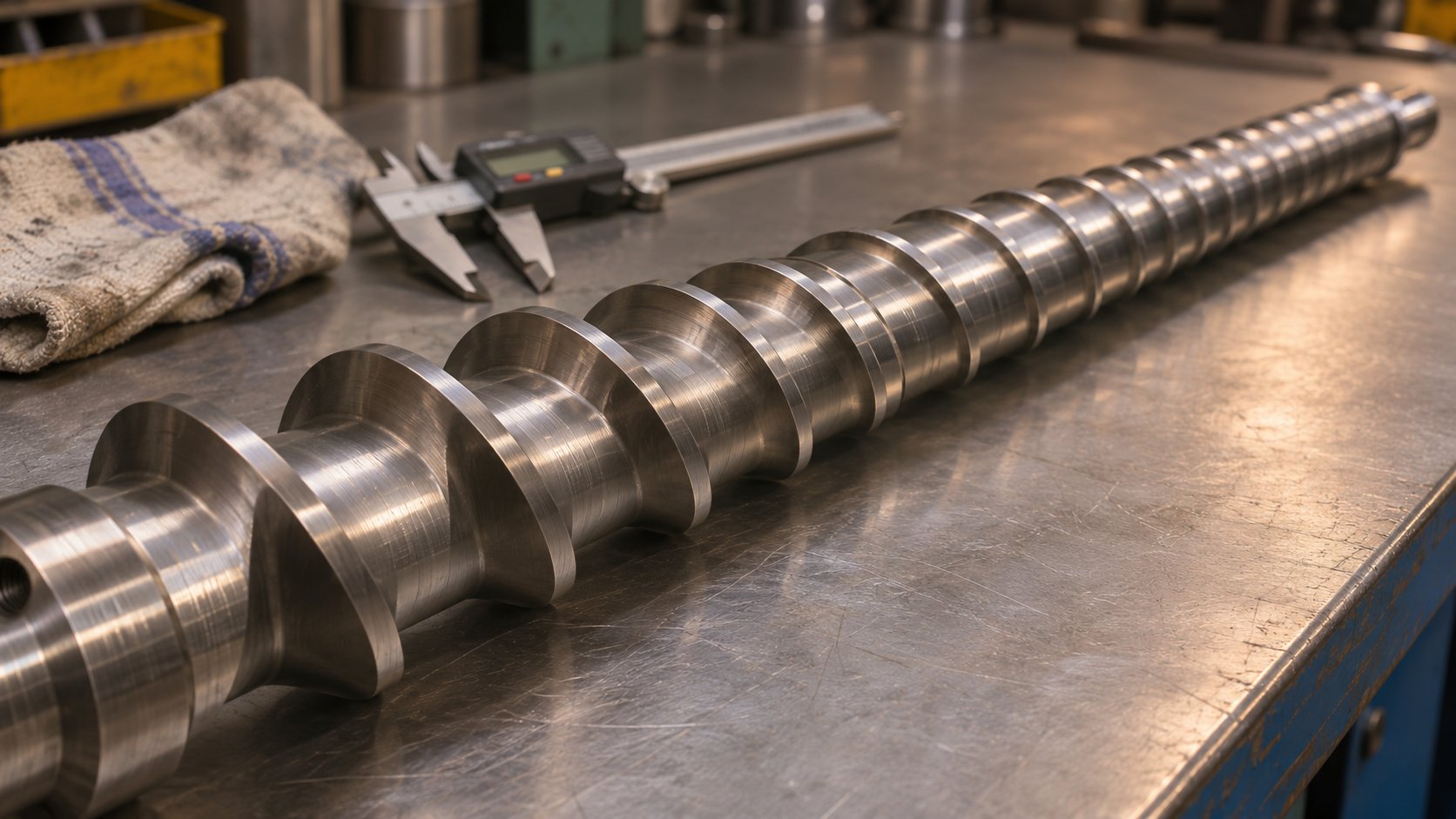
Think of the injection screw as a three-stage pump. The feed zone pulls solid pellets in and begins pushing them forward. The transition (or compression) zone applies increasing pressure and shear, melting the material and squeezing out air that was trapped between the pellets. The metering zone homogenizes the melt and delivers it at consistent pressure to the front of the barrel for injection.
Each zone accomplishes its task through precise flight geometry — the depth, pitch, and clearance of the helical flights machined into the screw. When those flights wear down, the screw's ability to compress and degas the melt deteriorates in measurable ways:
- Reduced flight depth in the compression zone lowers the compression ratio — the ratio of feed-zone channel depth to metering-zone channel depth. A screw designed with a 2.5:1 compression ratio that wears to an effective 1.8:1 no longer squeezes air out of the pellet bed aggressively enough. Entrained air passes through to the metering zone still in bubble form, carried forward into the shot.
- Worn flight lands increase the clearance between the screw's outer diameter and the barrel wall. Material slips backward over the flight crests instead of being pushed forward efficiently. This backflow reduces pumping effectiveness and creates localized pockets of resin that cycle back and forth without advancing — essentially small dead zones that accumulate heat exposure.
- Check-ring (non-return valve) wear compounds the problem. A worn check ring does not seal cleanly during injection, allowing melt to leak backward past the valve. This backflow reduces effective injection pressure — meaning the cavity receives less packing force than the controller indicates — and it exposes the leaked material to additional thermal cycling, both of which contribute to void formation and gas generation.
The diagnostic clue is often hiding in the data you already collect. Inconsistent shot weight, fluctuating cushion position, and gradually increasing screw recovery time all point toward worn plasticizing components losing their ability to process material consistently. If you're seeing bubbles in injection molded boxes that test weak under load, and your cushion size wanders more than a millimeter between cycles, the screw and check ring deserve a physical inspection before you touch another process setting.
Barrel Clearance, Residence Time, and Degradation
Barrel wear works hand-in-hand with screw wear, but its consequences follow a slightly different path. As the barrel bore enlarges from abrasive resins, glass-filled compounds, or simple long-term use, the clearance between screw and barrel wall increases beyond the designed tolerance. That wider gap reduces the shear and mixing energy applied to the melt, leaving pockets of unevenly melted or poorly mixed material that carry through into the part.
More critically, increased clearance creates stagnation zones where resin lingers far longer than intended. Residence time — the total duration material spends inside the heated barrel — is one of the most underappreciated factors in bubble formation. Polymers are sensitive to heat over time, not just temperature alone. A resin that processes cleanly at 260 °C with a 90-second residence time can degrade significantly at the same temperature if residence time stretches to four or five minutes due to worn components, an oversized barrel, or production interruptions.
When polymer chains break down from excessive thermal exposure, they release volatile compounds directly into the surrounding melt. These degradation gases nucleate into bubbles that behave identically to trapped-air bubbles in a heat-gun test — they expand outward when warmed — but their source is internal chemical decomposition rather than mechanical air entrapment. You'll often notice telltale signs before the bubbles become obvious: dark streaks or discoloration in the part, a burning odor at the nozzle, or occasional charred particles that appear in otherwise clean shots. These are the early warnings that material degradation is underway inside the barrel.
Air bubbles in PVC injection molding deserve special mention here because PVC is exceptionally sensitive to both shear and residence time. Even modest barrel wear that would be tolerable with polyethylene or polypropylene can push PVC into decomposition, releasing hydrochloric acid gas that not only forms bubbles but actively corrodes the barrel and screw — accelerating the very wear that caused the problem. For PVC processing, barrel and screw condition monitoring must be tighter and more frequent than for most other resins.
Matching Screw Geometry to Resin and Application Requirements
Wear is only half the hardware equation. Even a brand-new screw can generate bubbles if its geometry doesn't match the resin being processed. A general-purpose screw with a moderate compression ratio and no specialized mixing section may work acceptably for easy-flow polyethylene — but place it in a machine running hygroscopic nylon or shear-sensitive polycarbonate, and you'll encounter problems that look like process defects but are actually hardware mismatches.
Several geometry parameters determine how well a screw handles a given resin:
- Compression ratio must match the resin's bulk density change during melting. Semicrystalline materials like nylon and PET undergo a larger volume change than amorphous materials like ABS or polycarbonate. Too low a compression ratio for a semicrystalline resin leaves unmelted pellets in the melt stream; too high a ratio for a heat-sensitive amorphous resin generates excessive shear heat and triggers degradation off-gassing.
- L/D ratio (screw length to diameter) affects how much melting, mixing, and degassing can occur along the screw's length. A standard screw with an L/D of 20:1 may not provide enough residence in the transition zone for a high-viscosity engineering resin, leaving the melt inconsistently plasticized and prone to unmelted inclusions that trap air pockets around them.
- Mixing-section design — features like Maddock mixers, spiral elements, or barrier flights — improves temperature uniformity and disperses additives more thoroughly. For resins where colorant carriers tend to outgas, an effective mixing section breaks down concentrate clumps early in the plasticizing process, reducing localized volatile release downstream. Barrier screws, which physically separate solid and molten polymer, can dramatically improve melt homogeneity for semicrystalline resins that are difficult to melt uniformly.
Material retention is the final concern that ties screw geometry and wear together. Dead spots — areas where resin stagnates due to poor check-ring design, worn flight edges, or geometric transitions that create pockets — allow small amounts of material to sit under heat for far longer than the average residence time. That stagnant material degrades, and it periodically breaks free and enters the melt stream as a slug of degraded polymer loaded with volatile gases. The result is intermittent bubble defects: several clean shots followed by one or two shots with scattered gas bubbles, repeating in a frustratingly random pattern that resists every process adjustment you try.
When your troubleshooting has confirmed that worn or mismatched plasticizing hardware is the root cause — through cushion instability, inconsistent recovery time, degradation signs, or persistent bubbles that don't respond to material and process corrections — the practical next step is replacing or upgrading the screw and barrel to match your specific resin, machine, and application. NANHAIYA's custom injection molding screw barrels are designed around this exact need. Their technical review evaluates screw geometry, existing wear patterns, melting performance, mixing efficiency, and material-retention concerns to recommend a screw-and-barrel combination matched to your machine specifications and the resin you actually run — not a generic replacement pulled from a catalog. For maintenance teams that have worked through the diagnostic sequence and landed on a hardware-related bubble source, that kind of application-specific matching is what closes the gap between identifying the problem and actually solving it.
Hardware condition determines the quality of the melt your mold receives. A worn screw delivers inconsistent compression. A worn barrel allows stagnation and degradation. A mismatched geometry forces trade-offs that process settings alone cannot resolve. Addressing these mechanical foundations puts every upstream correction — drying, venting, parameter tuning — on solid ground. The question that remains is how to sequence all of these corrective levers into a single, efficient workflow that doesn't waste cycles or chase the wrong cause first.
A Prioritized Troubleshooting Workflow for Bubble Defects
You've identified how each bubble type forms, which resins carry the highest risk, how process parameters interact, what mold-design limits look like, and when worn plasticizing hardware is the hidden culprit. The challenge most molders face isn't a lack of knowledge — it's knowing where to start when a defective part lands on the bench. Jumping straight to a pack-pressure increase or a vent rework without confirming the root cause wastes cycles, burns production time, and can introduce entirely new defects along the way.
Experienced molding engineers don't troubleshoot randomly. They follow a logical sequence — low-cost, high-probability checks first, expensive hardware and tooling changes last. The workflow below mirrors that real-world discipline and gives you a repeatable path through any injection molding bubbles problem you encounter.
Always rule out moisture and material issues before changing process parameters or modifying tooling.
That principle saves more wasted hours than any single parameter adjustment ever will. Here is the complete six-step sequence:
- Confirm the bubble type. Cross-section the part through the defect area and examine under magnification. Then perform the heat-gun diagnostic on a freshly molded sample — within a few hours of production. If the bubble collapses inward, you have a vacuum void. If it expands outward, you're dealing with trapped gas or moisture. This single test splits your entire troubleshooting path in two and prevents the most common mistake: applying a packing fix to a gas problem, or chasing vents when undried resin is the real source.
- If moisture bubble — verify drying first. Check that the dryer is reaching its target dew point (not just target temperature). Confirm material has been drying for the full recommended duration. Inspect the hopper lid seal, the feed-throat connection, and the supply and return hoses — a supply hose that feels lukewarm instead of hot signals inadequate heat delivery. Measure actual material moisture content if a moisture analyzer is available. For hygroscopic resins like nylon or polycarbonate, this step alone resolves the majority of bubble complaints.
- If vacuum void — address packing and geometry. Identify the thickest section of the part and confirm that the void sits at or near its geometric center. Increase pack pressure in 5 to 10 MPa increments while monitoring cushion stability. Extend hold time to ensure the gate has not frozen off prematurely — if the cushion drops sharply early in the hold phase, the gate may be sealing before enough material reaches the thick zone. When voids in injection molded PP boxes remain weak despite aggressive packing, the wall section is likely too thick for the gate to service, and a design review becomes necessary.
- If trapped gas — inspect vents and speed profile. Pull the mold and examine vent channels at last-fill locations for residue buildup or compression damage. Clean or re-cut vents to their original depth specification. On the process side, reduce injection speed in the zones where bubbles concentrate, or implement a multi-stage speed profile that slows the melt front through air-trap-prone features like deep ribs or converging flow paths. Check screw decompression (suck-back) settings — excessive decompression after recovery can draw air into the nozzle tip, seeding bubbles into the next shot.
- If initial corrections fail — escalate to machine and mold hardware. Inspect the screw flights, check ring, and barrel bore for wear. Run a cushion-stability test over 20 consecutive shots: variation greater than 1 mm suggests check-ring leakage or worn metering-zone clearance. On the mold side, evaluate whether gate size limits effective hold duration, whether additional vents are needed in underserved cavity regions, or whether cooling-channel placement near thick sections can be improved. These changes carry higher cost and longer lead times, which is exactly why they belong later in the sequence — not as a first response.
- Evaluate material batch quality, regrind percentage, and additive compatibility. A new resin lot, a higher-than-normal regrind ratio, or a switch in colorant masterbatch can all introduce volatiles that weren't present in the previous production run. Compare the current material batch against the validated baseline. If regrind content has crept above the qualified percentage, or if the regrind has been stored without re-drying, those factors alone can explain a sudden spike in bubble defects. Blowing-agent contamination from shared equipment is another variable worth investigating when bubbles appear without any other process or tooling change — even trace residues from a previous foam-grade run can produce unexpected gas in subsequent solid-part production. When bubbles in injection molded PP boxes prove weak enough to raise recycling cost concerns, confirming material purity protects not just part quality but also the value of the regrind stream downstream.
Start With Material and Moisture Verification
Steps one and two sit at the top of the sequence for a reason: they cost nothing but a few minutes of inspection time, and they address the single most common source of bubbles in plastic parts produced from hygroscopic resins. A dryer that quietly drifted off its dew-point target overnight, a hopper lid left open during a shift change, or a bag of resin staged on a cold warehouse floor that collected condensation — any of these can flood the barrel with moisture and produce defects that look exactly like a process or tooling failure. Ruling them out first prevents you from ever reaching for process adjustments that weren't needed.
Escalate Through Process, Mold, and Machine Checks
Steps three and four are where process knowledge earns its value. You already know the bubble type from step one, so you're making targeted adjustments — not guessing. Vacuum voids get more packing. Trapped gas gets better venting and a slower fill profile. Each change is incremental, documented, and given enough shots to confirm the result before moving to the next variable. This discipline prevents the cascading parameter drift that happens when molders make multiple changes at once and can no longer tell which adjustment actually helped.
Step five acknowledges a reality that every production floor eventually faces: sometimes the mold or machine has physically changed since validation. Vents wear shut. Check rings erode. Gates that were adequate for the original resin grade may be undersized for a reformulated material. These are not failures of process skill — they are maintenance realities that require hardware solutions.
When to Involve Tooling Changes or Component Replacement
The decision to modify steel or replace plasticizing components should come only after steps one through four have been completed without resolution. Tooling changes are expensive, time-consuming, and irreversible in ways that process adjustments are not. But when the data clearly points to a gate that freezes off too early, vents that cannot be cleaned back to specification, or a screw that no longer delivers consistent compression, delaying the hardware fix only extends the cycle of compensating adjustments that mask the root cause without eliminating it.
Step six — the material and additive audit — can technically be performed at any point, but it lands at the end of the formal sequence because batch-related issues are less frequent than drying, process, or wear-related causes. When they do occur, however, they explain defects that defy every other corrective action. Keeping a log of material lot numbers, regrind ratios, and masterbatch changes alongside your defect records makes this step a quick cross-reference rather than a forensic investigation.
Following this workflow consistently does more than solve individual bubble events. It builds institutional knowledge — a documented record of what was checked, what was changed, and what actually fixed the problem. That record is what separates a shop that reacts to every defect from scratch from one that resolves recurring issues faster each time they surface. And for the fixes that stick, the final piece of the puzzle is knowing how to verify they worked — not just visually, but through inspection methods rigorous enough to catch the defects that hide beneath the surface.
Inspection Methods and Acceptance Criteria for Bubble Defects
Fixing a bubble problem and proving it's fixed are two very different challenges. A molder who eliminates visible surface splay through better drying may still be shipping parts with internal voids buried deep in thick sections — invisible to the naked eye yet structurally significant under load. Bubbles in plastic parts from injection molding don't always announce themselves on the surface, and relying solely on what you can see creates a dangerous blind spot in your quality system.
The inspection method you choose must match the severity of the risk. A cosmetic housing and a safety-critical structural bracket may come off the same press, but they demand fundamentally different levels of scrutiny. Understanding what each inspection technique can — and cannot — reveal is what turns bubble prevention from a reactive exercise into a controlled, repeatable verification process.
Visual Inspection Limitations and Destructive Testing
Visual inspection is fast, free, and effective for exactly one scenario: surface bubbles on parts you can see through or examine under good lighting. A trained operator can spot blisters, splay marks, and surface voids quickly enough to keep up with production rates. For transparent components like lenses or light covers, even small subsurface inclusions scatter light and become obvious during a basic visual scan.
The problem starts with opaque parts. A black-pigmented bracket or a filled nylon connector can harbor a substantial vacuum void at the center of a thick boss — and the exterior surface looks perfectly normal. You could inspect a thousand parts visually and never catch a single internal defect. That's not a failure of the inspector; it's a physical limitation of the method. Light does not penetrate opaque polymers, and surface appearance tells you nothing about what's happening inside the wall.
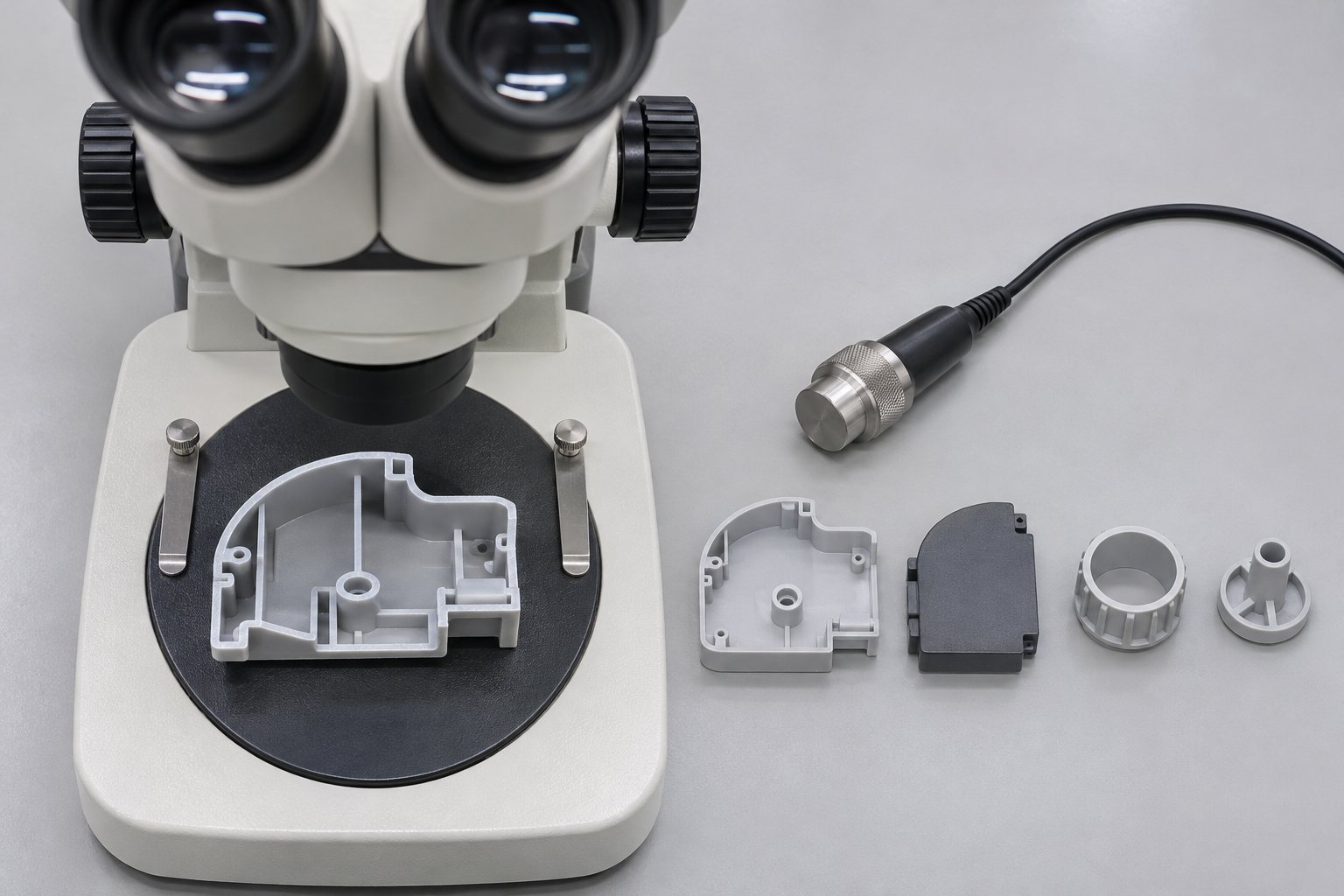
Cross-sectioning fills that gap at the cost of the part itself. The technique is straightforward: cut through the suspected thick section using a band saw or slow-speed diamond saw, then examine the exposed face under magnification — a stereo microscope at 10x to 30x provides enough resolution to characterize most voids clearly. You can measure bubble diameter, observe its shape (spherical voids suggest vacuum; irregular or elongated shapes suggest trapped gas distorted by flow), and pinpoint its position relative to the wall center.
Cross-sectioning is invaluable during initial troubleshooting and first-article qualification. However, as industrial CT scanning experts note, it carries inherent limitations. Cutting one plane exposes one slice of the part — a void sitting two millimeters to the left of your cut goes undetected. You destroy the specimen, losing any chance to retest or examine the three-dimensional relationship between the defect and the surrounding geometry. And sectioning a single part tells you nothing about whether the same defect exists across the entire production run. It's a snapshot, not a survey.
Cosmetic Bubbles vs Structural Voids and Acceptance Criteria
Not every bubble demands the same response. A small surface blister on a non-visible interior face of a consumer electronics housing may be perfectly acceptable — annoying to the molder's pride, perhaps, but functionally irrelevant. A void of the same size located beneath a snap-fit latch or a threaded boss on that same housing could cause field failures. The distinction between cosmetic and structural defects drives every acceptance decision.
Cosmetic bubbles sit at or near the surface and affect appearance without meaningfully reducing the part's load-bearing cross-section. They matter most on Class A visible surfaces, transparent components, and parts where customer perception of quality is tied directly to surface finish. Structural voids, by contrast, are internal cavities that reduce the effective wall thickness at their location. They create stress-concentration points where cracks can initiate under mechanical loading, impact, or thermal cycling. A part that meets dimensional specifications and looks flawless externally can still fail prematurely if a void sits along a critical load path.
Acceptance criteria should define — in writing, before production begins — the specific limits for each defect type. The parameters that matter most include:
- Maximum bubble diameter — often specified as an absolute dimension (e.g., no void larger than 0.5 mm) or as a percentage of wall thickness.
- Number of bubbles per part — a total count limit or a count within a defined region of the part.
- Proximity to critical features — voids near sealing surfaces, snap fits, threaded inserts, load paths, or weld lines carry disproportionate risk and may require tighter limits or zero-tolerance zones.
- Total void volume — for applications where cumulative porosity affects performance, a maximum allowable percentage of internal void volume relative to part volume may be specified.
- Surface-connected vs. encapsulated — a fully encapsulated internal pore behaves differently from a surface-connected opening that can act as a leak path or a crack-initiation site.
These criteria should be established collaboratively between the molder and the end-use customer during part qualification — not discovered after a shipment rejection. As one CT inspection laboratory emphasizes, clearly defined questions and desired outcomes create a more confident inspection design. When minimum defect size and acceptance limits are communicated before scanning or testing, they directly determine the resolution and analysis capability required.
Advanced Non-Destructive Evaluation Methods
When parts are safety-critical, high-value, or produced in volumes where destructive sampling cannot provide statistical confidence, non-destructive evaluation (NDE) methods close the gap between surface-level visual checks and part-destroying cross-sections.
Ultrasonic flaw detection offers a practical middle ground. A small transducer coupled to the part surface sends high-frequency sound waves through the material. Those waves travel until they hit a boundary — either the far wall of the part or an internal discontinuity like a void. A void generates an additional echo where none should exist, and a trained operator reading the echo pattern on a display screen can quickly verify material integrity. The inspection takes only seconds per test point and works well for parts with wall thicknesses above approximately 6 mm, though smaller transducers and higher frequencies can probe thinner sections. Ultrasonic testing is portable, relatively inexpensive, and fast enough for production-floor sampling — making it an excellent screening tool when you need to check multiple parts without cutting any of them open.
Industrial micro-CT scanning (X-ray computed tomography) represents the most comprehensive inspection available. The part rotates on a stage while X-ray projections are captured from every angle, then reconstructed into a full three-dimensional dataset. That dataset can be sliced virtually in any plane — no physical cutting needed — revealing every internal void, its size, shape, location, and spatial relationship to surrounding geometry. CT data supports quantitative porosity analysis: pore count, pore volume, distribution, and concentration within defined regions. For engineering teams investigating whether a recurring void correlates with a thick boss, a cooling imbalance, or a gate-location issue, CT provides the evidence to connect the defect to its probable cause.
The key constraint with CT scanning is resolution. The scan must be designed so that the minimum detectable feature size matches the acceptance criteria. A general rule: CT resolution should be approximately one-third of the smallest pore size you need to analyze quantitatively. A feature that's too small relative to the voxel size may still appear in the image, but it cannot be measured reliably — visibility and quantitative analysis are not the same thing.
Here is a progression of inspection methods ranked from simplest to most advanced, so you can match the technique to the application:
- Visual inspection — fast and free; catches surface bubbles and splay on visible or transparent surfaces; misses all internal voids in opaque parts.
- Cross-section and magnification — destructive; reveals internal defects along the cut plane; ideal for first-article qualification and troubleshooting; limited to one slice per cut.
- Heat-gun diagnostic test — semi-destructive (requires sectioning for best results); differentiates vacuum voids from gas or moisture bubbles; essential for directing the correct troubleshooting path.
- Ultrasonic flaw detection — non-destructive; detects internal voids through echo-pattern analysis; portable and production-floor friendly; effectiveness depends on part geometry and material.
- Industrial micro-CT scanning — non-destructive; provides full 3D visualization and quantitative void analysis; highest resolution and most complete data; best suited for critical components, failure analysis, and process validation across multiple samples.
Choosing the right inspection method isn't about always using the most advanced technology — it's about matching the tool to the engineering question. A cosmetic part with occasional surface blisters needs only visual inspection and perhaps a cross-section to confirm the bubble type. A structural automotive component with a zero-tolerance void specification near a load-bearing feature may justify CT scanning of first-article samples and ultrasonic spot-checks during production runs. Gas bubbles trapped in wax jewelry during investment-casting injection, for example, demand entirely different detection approaches than voids in a thick-walled PP container — the part geometry, material, and failure mode all shape the inspection strategy.
The inspection method you deploy is really the final link in a chain that begins with diagnosis and runs through material control, process optimization, mold design, and machine maintenance. Without a defined acceptance standard and a verification method capable of enforcing it, even a well-executed troubleshooting effort has no way to confirm its own success — and no way to catch the slow drift back toward defect territory that every production process experiences over time.
Putting It All Together for Bubble-Free Production
Diagnosis, material control, process discipline, tooling awareness, machine maintenance, and verified inspection — each of these elements solves a piece of the injection molding bubbles puzzle. Individually, they're useful. Linked together in the right sequence, they form a system that doesn't just fix bubble defects — it prevents them from recurring.
Three Principles That Prevent Recurring Bubble Defects
Every troubleshooting decision covered in this article traces back to three core principles. Commit them to your standard work and you'll spend far less time chasing defects that resist one fix after another:
- Identify the bubble type before attempting any correction. Vacuum voids, trapped-gas bubbles, and moisture-driven bubbles look similar on the surface but demand fundamentally different fixes. The heat-gun diagnostic and cross-section examination take minutes — skipping them can cost hours of misdirected process changes. An injection mold produces no bubbles consistently only when every corrective action targets the actual root mechanism, not a guess.
- Follow the prioritized troubleshooting sequence. Material and moisture verification first. Process parameter adjustments second. Mold and machine hardware last. This order reflects both probability and cost — the most common causes are the cheapest to check, and the most expensive interventions should only happen after simpler explanations have been ruled out. Jumping to tooling changes or component replacement without completing the earlier steps risks solving the wrong problem while the real one persists.
- Build acceptance criteria and inspection protocols into your quality system from the start. Defining maximum void size, allowable bubble count, and proximity limits to critical features during part qualification — not after a customer complaint — transforms bubble prevention from reactive firefighting into controlled process management. Matching the inspection method to the part's risk level ensures that injection molding bubbles in parts are caught before they ship, whether that means a simple visual check or a full micro-CT scan.
Building Long-Term Process Robustness
Solving today's bubble problem matters. Preventing tomorrow's matters more. Long-term robustness comes from maintaining the foundations that keep every variable inside its validated window: consistent melt quality delivered by properly matched and maintained plasticizing hardware, validated drying procedures verified by dew-point monitoring rather than assumed by timer settings, tooling maintained on schedule with vent cleaning and gate-condition checks built into preventive maintenance routines, and documented process baselines that make drift visible before it becomes a defect.
An injection molding bubbler — whether it refers to the cooling component inside the mold or the defect on the bench — only becomes a recurring headache when the system around it lacks structure. The shops that rarely fight bubbles aren't luckier. They've simply built the diagnostic logic, material discipline, and hardware maintenance into their daily operations so thoroughly that bubble defects get intercepted at the source, long before they ever reach a finished part.
Frequently Asked Questions About Injection Molding Bubbles
1. What causes bubbles in injection molding?
Three distinct mechanisms cause bubbles in injection molding. Vacuum voids form when thick wall sections shrink inward during cooling and pack pressure cannot compensate, leaving a hollow core. Trapped-gas bubbles occur when air is sealed inside the cavity due to poor venting, jetting flow patterns, or volatile gases released by thermal degradation of the resin or additives. Moisture bubbles appear when hygroscopic resins like nylon, polycarbonate, or ABS carry absorbed water into the barrel, where it flashes to steam above 100 degrees Celsius. Identifying which mechanism is at work is essential because each type requires a fundamentally different corrective strategy — raising pack pressure solves voids but does nothing for moisture, and improving vents addresses trapped air but not shrinkage.
2. How do you tell the difference between a vacuum void and a gas bubble in a molded part?
The most reliable method is the heat-gun diagnostic test. Cross-section a freshly molded part (within about four hours of production) through the bubble, then gently warm the area with a heat gun until the polymer softens. A vacuum void collapses inward because atmospheric pressure pushes the softened skin into the empty cavity, producing a visible depression. A trapped-gas or moisture bubble expands outward because the pressurized gas inside pushes against the softened polymer, inflating the surface or even popping through. Timing matters — testing a part more than 16 hours old can give misleading results because ambient air may migrate through the polymer wall and infiltrate what was originally a vacuum void.
3. How do you get rid of bubbles in injection molding?
Start by confirming the bubble type using a cross-section examination and heat-gun test, then follow a prioritized sequence. For moisture bubbles, verify that your desiccant dryer is reaching the correct dew point and that the resin has dried for the full recommended time — this alone resolves most bubble issues in hygroscopic materials. For vacuum voids, increase pack pressure and hold time incrementally while checking that the gate has not frozen off prematurely. For trapped-gas bubbles, clean and inspect mold vents at last-fill locations and reduce injection speed in air-trap-prone zones. If these steps fail, escalate to machine-condition checks such as screw and barrel wear assessment, gate-size evaluation, and material-batch quality review. The key principle is to address low-cost, high-probability causes first before committing to expensive tooling or hardware changes.
4. Why does screw and barrel wear cause bubbles in injection molded parts?
The screw and barrel assembly is responsible for melting, compressing, and degassing the resin before injection. When screw flights wear down, the compression ratio drops and entrained air passes through to the metering zone without being squeezed out and dissolved into the melt. Worn flight lands increase clearance between the screw and barrel wall, allowing material to slip backward and creating stagnation zones where resin sits under heat far longer than intended. That extended residence time triggers thermal degradation, releasing volatile gases that nucleate into bubbles. A worn check ring compounds the issue by leaking melt backward during injection, reducing effective pack pressure delivered to the cavity. Diagnostic signs include inconsistent cushion position, fluctuating shot weight, and gradually increasing screw recovery time. Replacing worn components with application-matched screw barrels — such as those offered through NANHAIYA's custom technical review process — restores compression efficiency and melt consistency.
5. How can you detect internal bubbles in opaque injection molded parts?
Visual inspection only catches surface defects, so opaque parts require additional methods. Cross-sectioning the part through suspected thick sections and examining the exposed face under a stereo microscope at 10x to 30x magnification is the most accessible approach during troubleshooting and first-article qualification. For non-destructive evaluation, ultrasonic flaw detection sends high-frequency sound waves through the part wall and identifies internal voids through abnormal echo patterns — it is portable and fast enough for production-floor sampling. Industrial micro-CT scanning provides the most comprehensive analysis, generating a full three-dimensional dataset that reveals every internal void along with its size, shape, and location without destroying the part. The right method depends on the part's criticality: cosmetic housings may only need periodic cross-sections, while safety-critical structural components may justify CT scanning during qualification and ultrasonic spot-checks during production.
Written by
Nanhaiya Technical Team
Zhoushan Nanhaiya Plastic Machinery Co., Ltd.
The Nanhaiya technical team supports screw and barrel manufacturing projects through application review, technical communication, custom manufacturing coordination, and production and quality control.
Discuss Your Application
Related Articles
More insights on screw barrel technology and plastics processing.
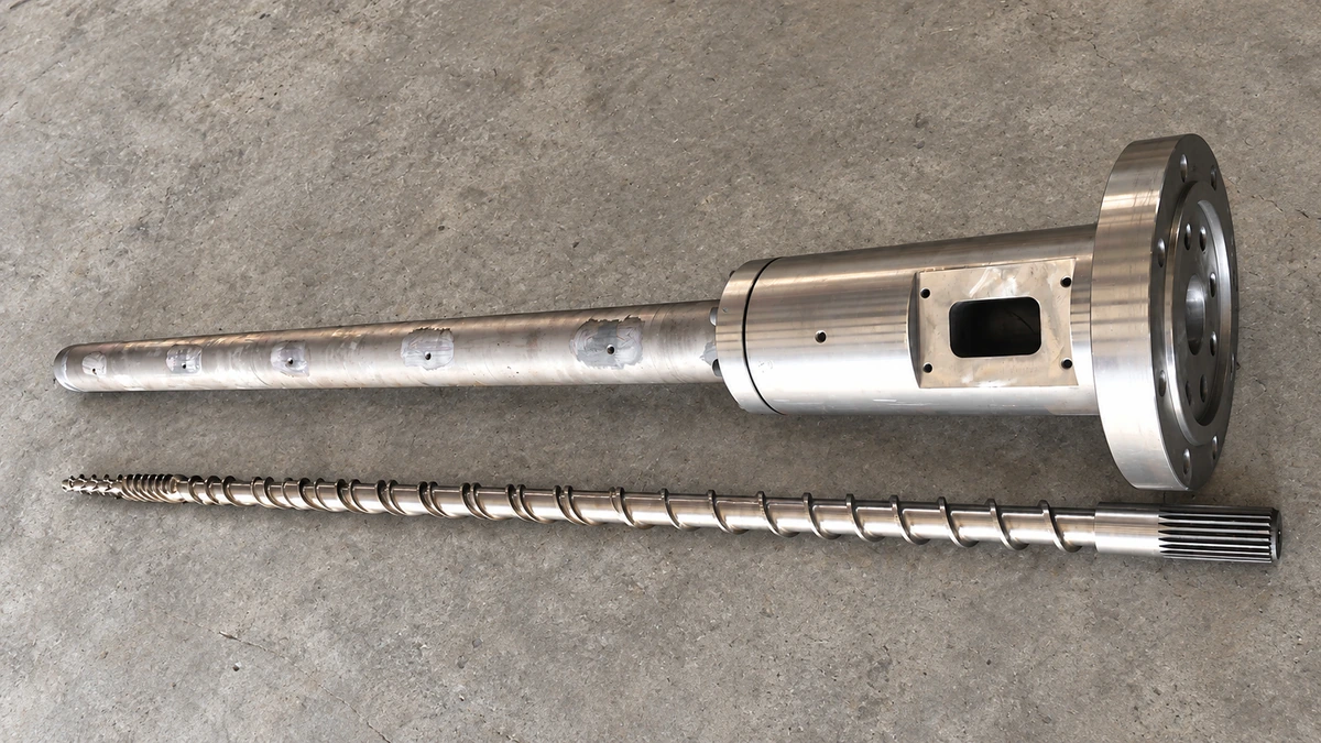
Why Your Single Screw Extruder Design Causes Extrusion Defects
Nov 13, 2026
Learn how single screw extruder design parameters—L/D ratio, compression ratio, channel depth, and mixing elements—affect melt quality, throughput, and defects.
Read Article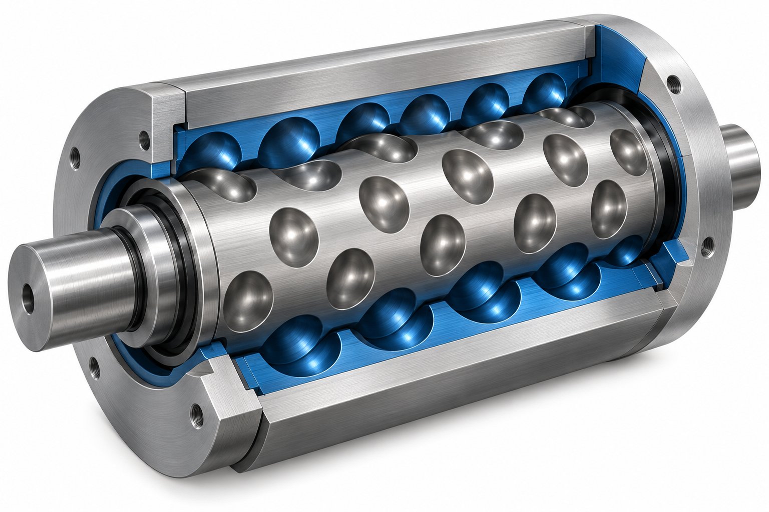
Cavity Transfer Mixer: The Blender Your Extruder Didn't Know It Needed
Nov 13, 2026
Learn how a cavity transfer mixer (CTM) upgrades single-screw extruder mixing. Covers working principles, key parameters, integration, applications, and comparisons.
Read Article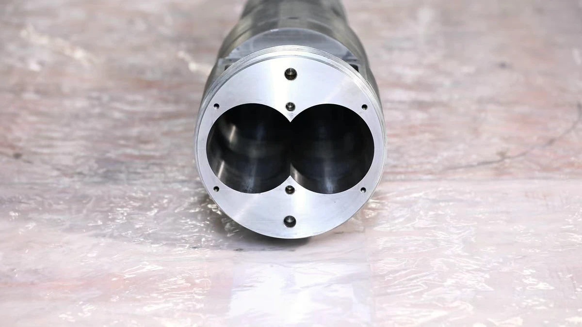
Extruder Barrel Alignment Decoded: Tolerances Most Plants Miss
Nov 13, 2026
Learn extruder barrel alignment tolerances, laser procedures, thermal offsets, and proactive schedules most plants miss — for single-screw and twin-screw lines.
Read ArticleLooking for something else?
Search by material, symptom or product and jump straight to the relevant page.
These are navigation suggestions based on keyword matching — not a quotation, not a delivery commitment, and not a substitute for engineering review. Final specification is confirmed by our engineers against your drawings and processed material.
Need help with screw barrel selection?
Share your machine model, processed material and application. Our team can help with pricing and technical support.