

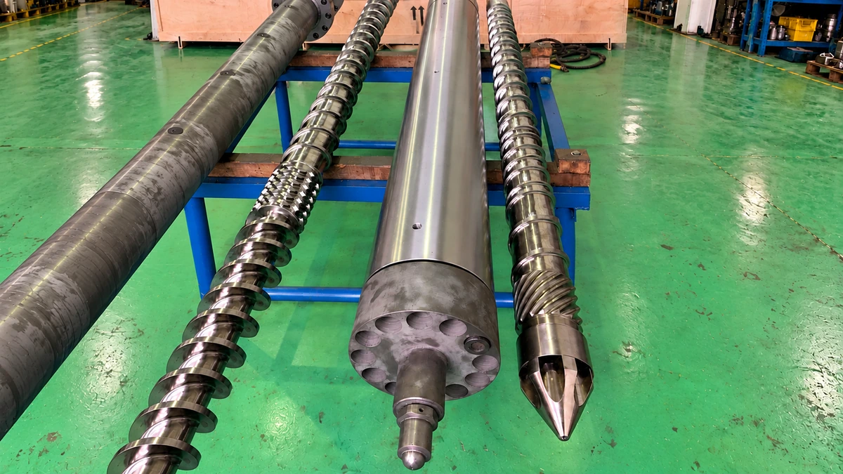
What Injection Molding Cushion Really Means
Search for "cushion in injection molding" across a dozen plastics resources, and you'll quickly run into a frustrating problem: different sources define it differently. Some describe it as the screw position at the very end of the hold phase. Others call it the farthest-forward point the screw reaches at any moment during injection. These two positions are not always the same number, and confusing them can lead you down the wrong diagnostic path when something goes wrong on the press.
This ambiguity isn't just academic. It shapes how operators read their machine data, how engineers set process parameters, and how quality teams interpret shot-to-shot variation. Before diving into why your cushion might be drifting, it's worth clearing up this confusion once and for all.
Two Industry Definitions and Why They Cause Confusion
The dual-definition problem stems from how different machines and training programs describe screw movement. During a typical cycle, the screw travels forward under velocity control to fill the cavity, then transitions to pressure-controlled packing and holding. Two distinct screw positions emerge from this sequence:
- Farthest-forward screw position: The minimum screw position recorded at any point during injection — often occurring right at or just after the velocity-to-pressure switchover.
- End-of-hold screw position: Where the screw sits after the hold timer expires, which may differ from the farthest-forward point if screw bounceback occurs.
Sometimes these two values are identical. Yet when the process calls for lower holding pressures — or when compressible materials allow the screw to rebound slightly — the numbers diverge. As RevPart notes, it's essential to understand which definition your specific machine uses before interpreting any cushion data. Most industry training programs and scientific molding references, however, align on one primary injection molding cushion definition: the small volume of melt remaining in front of the screw at the end of the hold phase.
That's the definition this article uses throughout, and it's the one you'll encounter most frequently in process documentation, validation protocols, and SPC monitoring.
How the Melt Cushion Actually Functions
Imagine squeezing a syringe. As long as there's fluid ahead of the plunger, you can transmit force through that fluid into whatever you're injecting. The moment the plunger hits the bottom of the barrel with no fluid left, your ability to push anything goes to zero. The injection molding screw works the same way.
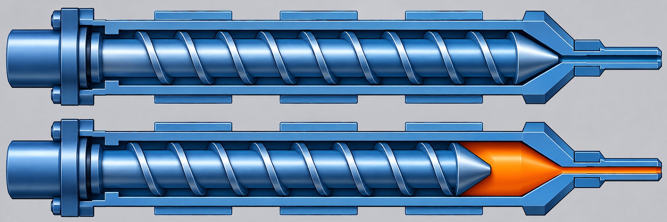
During the pack and hold phases, the screw acts as a hydraulic piston. The melt cushion — that residual column of molten plastic sitting between the screw tip and the nozzle — is the medium through which hold pressure travels into the cavity. This compressible melt column allows the machine to continue compensating for volumetric shrinkage as the part cools and solidifies inside the mold.
Injection molding cushion is the small amount of molten plastic that remains in front of the screw at the end of the hold phase. It serves as the pressure-transmitting medium that allows pack and hold pressure to reach the mold cavity. Without it, the screw bottoms out against the barrel end cap and the pressure path is severed.
When the cushion drops to zero, the screw physically contacts — or nearly contacts — the barrel end cap. At that point, there's nothing left to push on. RJG's Jim Clifford puts it simply: "Without having a cushion, you cannot transmit pressure into the cavity. Once the screw bottoms out, it no longer has anything to push on." The result is cavity pressure that becomes unpredictable from shot to shot, making it nearly impossible to hold parts within tolerance.
Some machines even include built-in safety features that automatically cut injection pressure when the screw position drops below a threshold — typically around 0.100 inches — to prevent damage to the screw tip and end cap. If you're unaware that your press has this protection, you might never notice the pressure drop, yet your parts will reflect it in the form of cushion variation and inconsistent packing.
The takeaway is straightforward: the melt cushion isn't just a number on the controller screen. It's the physical link between your machine's hydraulic force and the pressure your part actually experiences inside the mold. And when that link breaks — even briefly, even by a fraction of an inch — part quality suffers immediately. The real question becomes how much cushion you need, and what happens when you get it wrong in either direction.
Why Cushion Matters for Part Quality and Process Stability
Too many molders treat cushion as a "set it and forget it" value — a number they dial in during setup and never revisit until something obviously breaks. That mindset is risky. Injection molding cushion size directly controls whether pack and hold pressure actually reaches the cavity, and any deviation — too small, too large, or inconsistent — triggers a specific chain of defects that can be traced back to how that residual melt column behaves under pressure.
Understanding these cause-and-effect relationships turns cushion from an abstract number on your controller into a powerful diagnostic tool.
What Happens When the Screw Bottoms Out
Picture this: the hold phase is active, your machine displays the correct hold pressure on-screen, but the screw has already contacted the barrel end cap. What's really happening inside the barrel? Nothing productive. With zero melt ahead of the screw tip, there's no hydraulic medium to transmit force. The machine's hydraulic system may still be generating pressure, but that pressure has nowhere to go.
The consequences are immediate. The cavity no longer receives the compensating flow it needs as the plastic cools and shrinks. Thick sections around ribs and bosses develop sink marks. Dimensional variation increases because the amount of material packed into the cavity changes from shot to shot. In severe cases, you'll see outright short shots — parts that simply aren't complete because the final fraction of material never arrived.
Here's what catches many operators off guard: the screw doesn't have to stay bottomed out for an entire cycle to cause problems. Even momentary bottoming — where the screw contacts the end cap briefly before rebounding — can produce an inconsistent cushion that disrupts packing uniformity. RJG notes that when this happens, "actual cavity pressure will be all over the place," making it far more difficult to overcome normal viscosity shifts. One cycle might pack perfectly while the next falls short, and the resulting part-weight scatter makes statistical process control nearly impossible.
Defects Linked to Excessive Cushion
If zero cushion is clearly bad, you might assume that more is always better. It isn't. Excessive material cushion in injection molding introduces its own set of problems — ones that are subtler and often harder to diagnose.
When too much melt sits idle in front of the screw, that material experiences extended residence time at processing temperature. Heat-sensitive resins like POM, PVC, or certain nylons begin to degrade. You'll see the evidence as burn marks, splay, brown streaks, or generalized discoloration in the finished part. The longer the melt sits, the worse the degradation becomes — especially on machines where the barrel capacity far exceeds the actual shot size.
There's a compressibility issue as well. A larger melt column means more material that can compress and expand unpredictably during packing. This introduces injection molding cushion variation from shot to shot, even when every other process parameter holds steady. The result is inconsistent part weight and dimensions that drift in ways that don't correlate cleanly with any single machine setting.
Jim Clifford at RJG shared a telling example: after discovering a screw that was six inches shorter than specification, his team realized the cushion they believed was 0.250 inches was actually 6.250 inches. That oversized melt column acted "like a sponge," absorbing hold pressure instead of transmitting it efficiently. When the correct-length screw was installed and cushion dropped to its intended range, the process suddenly overpacked every part — proving just how dramatically injection molding cushion size affects what happens inside the cavity.
The table below maps each cushion condition to the physical mechanism at work and the defects you're most likely to encounter:
| Cushion Condition | Physical Mechanism | Associated Defect Risks | Affected Quality Attributes |
|---|---|---|---|
| Zero cushion | Screw contacts barrel end cap; no melt available to transmit hold pressure | Short shots, severe sink marks, incomplete packing | Part weight, dimensional accuracy, structural integrity |
| Insufficient cushion | Minimal melt column; intermittent bottoming out causes erratic pressure transmission | Sink marks, part-weight scatter, intermittent shorts | Dimensional consistency, cosmetic appearance, shot-to-shot repeatability |
| Optimal range | Adequate melt column transmits hold pressure consistently; minimal excess residence time | Low defect risk when other parameters are controlled | Stable weight, dimensions, and surface finish |
| Excessive cushion | Large melt volume increases compressibility variation and extends thermal exposure | Burn marks, splay, discoloration, degradation-related black specks, inconsistent packing | Color consistency, material integrity, dimensional stability, part weight uniformity |
Notice that both extremes produce injection molding inconsistent cushion behavior — just through different mechanisms. Too little, and pressure transmission fails. Too much, and compressibility absorbs the energy you're trying to deliver. The optimal window between these extremes isn't universal; it depends on your screw diameter, resin type, part geometry, and shot-size-to-barrel-capacity ratio — factors that shape exactly how to select the right cushion for a given application.
How to Set Injection Molding Cushion Size by Resin and Machine
Knowing that both too little and too much cushion cause problems is one thing. Choosing the right target value for your specific application is another challenge entirely. The melt cushion in injection molding isn't a fixed, universal number — it shifts based on the machine you're running, the resin flowing through the barrel, and the geometry of the part you're packing. Yet walk through most molding shops, and you'll find the same 3-6 mm setting copied from job to job with little adjustment. That approach works until it doesn't, and when it fails, the root cause is often a mismatch between the cushion value and the real-world demands of the application.
Getting this right requires understanding what actually drives cushion selection — and why a number that works perfectly on one press can cause headaches on another.
General Starting Points for Cushion Size
Industry literature commonly references a starting range of approximately 3-6 mm (0.125-0.25 in) for injection molding cushion size. This range appears across training manuals, machine OEM documentation, and scientific molding coursework. It's a reasonable first approximation — but treating it as a universal rule is where many molders run into trouble.
Here's why: that linear distance represents a vastly different volume of melt depending on the screw diameter. Imagine a 4 mm cushion on a 25 mm diameter screw. The volume of residual melt is tiny — roughly 1.96 cm³. That same 4 mm on a 90 mm screw? You're looking at about 25.4 cm³, nearly thirteen times more material sitting in front of the screw tip. The larger melt column compresses differently under hold pressure, absorbs more energy, and retains heat longer. Copying a linear cushion value from a small machine to a large one — or vice versa — without accounting for this volumetric difference is a recipe for inconsistent packing.
This is exactly why barrel utilization percentage matters. When your shot size consumes only a small fraction of the barrel's total capacity, even a modest linear cushion can represent a disproportionately large residence volume. A machine running a 30-gram shot on a barrel rated for 500 grams has far more thermal exposure risk than the same shot on a properly sized 80-gram barrel — and the cushion behavior reflects that mismatch.
Before settling on a cushion target, consider this checklist of factors that directly influence what is cushion in injection molding for your specific setup:
- Screw diameter: Larger diameters amplify the volumetric impact of every millimeter of linear cushion.
- Shot size as a percentage of barrel capacity: Ideally, your shot should consume 20-80% of the barrel's rated capacity. Outside this range, cushion behavior becomes less predictable.
- Resin type: Crystallinity, viscosity, and thermal sensitivity all shift the optimal cushion window.
- Part geometry: Thick-walled parts with heavy ribs or bosses demand more packing and benefit from a cushion large enough to sustain prolonged hold pressure without risk of bottoming out.
- Pack pressure requirements: Higher hold pressures compress the melt column more aggressively, so the starting cushion must account for that compression to avoid reaching zero.
A practical guideline from JeekMould reinforces this point: "The machine manufacturer's recommendations should take priority because the same distance does not represent the same melt volume on every machine." When transferring a mold to a different press, copying the linear cushion value alone rarely reproduces the same process. Screw diameter, shot capacity, and the resulting melt volume all need to be recalculated.
How Resin Properties Influence Cushion Selection
Resin selection doesn't just change your melt temperature and fill speed — it fundamentally shifts how the cushion behaves and how precisely you need to control it. The distinction between semi-crystalline and amorphous polymers is the most significant dividing line, but filled versus unfilled grades and viscosity characteristics add further layers of complexity.
Semi-crystalline resins — think nylon (PA), POM (acetal), PBT, polyethylene, and polypropylene — undergo a distinct phase change as they cool. Ordered crystalline regions form and contract, producing higher volumetric shrinkage than their amorphous counterparts. As Aprios Custom MFG explains, these materials "melt and solidify over a narrower temperature range, and as they cool, crystalline regions form and contract," creating higher directional shrinkage and greater warpage risk. That elevated shrinkage means the cavity demands more compensating flow during hold — and the cushion must be both large enough to sustain that flow and stable enough to deliver it consistently. Even small fluctuations in melt cushion injection molding values with semi-crystalline resins can produce noticeable dimensional shifts in the finished part.
Amorphous resins — ABS, polycarbonate (PC), PMMA (acrylic), and polystyrene — behave more predictably. Their molecular chains lack the ordered crystalline structure, so they soften gradually and shrink more uniformly. This generally makes the packing phase less demanding and the cushion less sensitive to minor variations. However, amorphous materials bring a different concern: many are more vulnerable to thermal degradation when residence time increases. An oversized cushion on an amorphous resin may not cause packing issues, but the extra time at melt temperature can trigger yellowing, reduced impact strength, or surface defects like splay. If you're wondering how to increase cushion injection molding values for an amorphous material, proceed cautiously — the additional melt volume may solve one problem while creating another.
Glass-filled and mineral-filled resins introduce mechanical complications that affect cushion stability over time, not just during a single run. Abrasive fillers accelerate wear on the check ring, screw flights, and barrel bore. As John Bozzelli of Injection Molding Solutions notes, check-valve wear under high-pressure conditions with filled resins can be dramatic — scoring, scratching, and carbon buildup that compromise sealing integrity. A worn check ring allows melt to leak backward past the screw tip during injection, directly reducing the cushion and introducing shot-to-shot variation. What starts as a stable 4 mm cushion on a new screw can gradually erode to 2 mm or less over thousands of cycles as the check ring loses its ability to seal. Higher-viscosity filled compounds also require more injection pressure to push through the gate, which compresses the melt column more aggressively and demands a slightly larger starting cushion to maintain margin.
The table below summarizes how these resin categories influence what is melt cushion in injection molding and its practical setup:
| Resin Category | Shrinkage Behavior | Cushion Sensitivity | Key Consideration |
|---|---|---|---|
| Semi-crystalline (PA, POM, PBT, PE, PP) | High volumetric shrinkage; directional | High — demands tighter cushion control for consistent packing | Ensure cushion supports sustained hold pressure to compensate for crystallization shrinkage |
| Amorphous (ABS, PC, PMMA, PS) | Lower, more uniform shrinkage | Moderate — more forgiving on packing but sensitive to residence time | Avoid excessive cushion that extends thermal exposure and risks degradation |
| Glass-filled / mineral-filled | Reduced shrinkage in flow direction; higher across flow | High — abrasive wear degrades check-ring seal over time | Monitor cushion trend for gradual decline as check ring and barrel wear; plan maintenance intervals accordingly |
| High-viscosity / high-flow resins | Varies by base polymer | Moderate to high — viscosity extremes affect screw recovery and melt compressibility | High-viscosity resins compress the cushion more under hold pressure; low-viscosity resins increase backflow risk through worn seals |
The practical takeaway is that cushion selection can't be divorced from material science. A process engineer who dials in a cushion value based solely on the 3-6 mm rule — without considering whether they're running a semi-crystalline nylon or an amorphous polycarbonate, a neat resin or a 30% glass-filled grade — is leaving part quality to chance. The right cushion target emerges from the intersection of machine geometry, resin behavior, and part requirements. And even a perfectly chosen starting value won't stay optimal forever, because the cushion you set today interacts dynamically with everything upstream — especially the velocity-to-pressure switchover that determines how much material remains in front of the screw when packing begins.
Cushion and the Velocity-to-Pressure Switchover Relationship
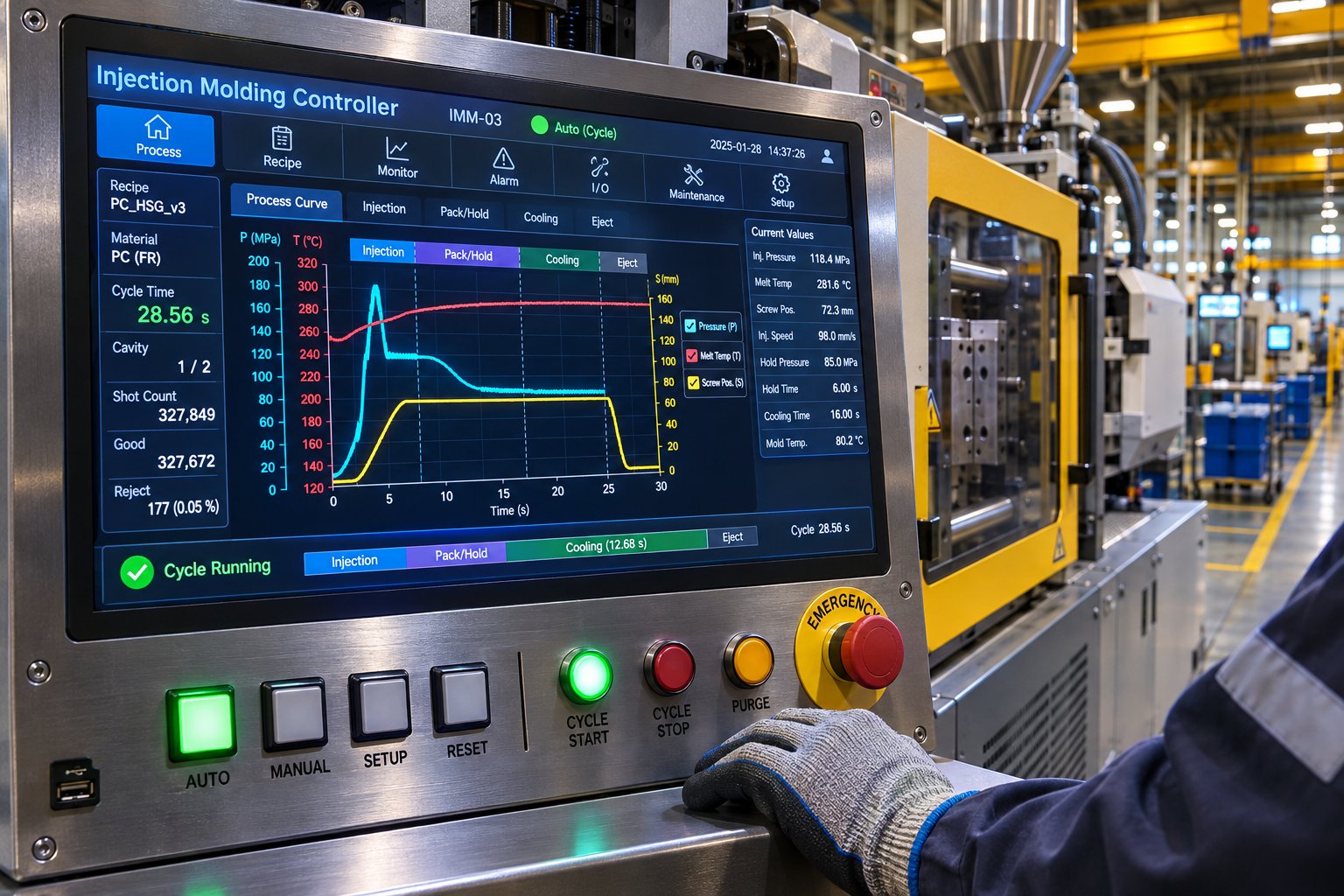
The dynamic between the injection molding cushion and the velocity-to-pressure (V/P) switchover is one of the most misunderstood relationships in injection molding — and one of the most consequential. Your cushion value doesn't exist in isolation. It's shaped directly by the moment the machine transitions from speed-controlled filling to pressure-controlled packing. Get that transition point wrong, and no amount of cushion adjustment will save your parts.
This connection runs deeper than a single machine setting. In scientific molding methodology, the four plastic variables — plastic pressure, plastic flow rate, plastic temperature, and plastic cooling rate — govern everything the polymer experiences inside the mold. The V/P switchover sits at the intersection of flow rate and pressure, and the cushion is where the outcome of that intersection becomes measurable. Understanding this link transforms the cushion from a number you monitor into a diagnostic signal you can actually interpret.
Transfer Position and Its Effect on Cushion
During the fill phase, the screw moves forward under velocity control. The machine doesn't care about pressure during this stage — its job is to push melt into the cavity at a prescribed speed. At the V/P switchover point (also called the transfer position), the machine shifts gears. Velocity control ends, and pressure control takes over for packing and holding. The amount of melt remaining in front of the screw at that exact moment defines the starting point from which your final cushion will be determined.
Here's where things get interesting — and where many processes go wrong.
When the transfer position is set too late, the screw travels too far forward during the velocity-controlled fill phase. The cavity overfills under high-speed injection before the machine ever switches to pressure control. Two problems emerge simultaneously. First, the overfilled cavity may flash or experience internal stress from excessive pressure spikes. Second — and more relevant to this discussion — the screw has consumed too much of its available stroke. The residual melt column is now dangerously thin. During the hold phase, the screw may bottom out or hover so close to zero that even minor shot-to-shot viscosity shifts push it into contact with the barrel end cap. Your cushion alarm fires, parts vary wildly, and the root cause isn't the cushion setting at all. It's the transfer point.
When the transfer position is set too early, the opposite scenario unfolds. The machine switches to pressure control before the cavity is adequately filled. Plenty of melt remains in front of the screw — the cushion looks healthy on the controller screen — but the cavity is short. Pack pressure alone typically cannot complete the fill because it operates at much lower flow rates than the velocity phase. You end up with parts that show incomplete features, poor knit-line strength, and low part weight, all while the cushion reading suggests everything is fine.
This is the trap: a good-looking cushion number doesn't guarantee a good part. The switchover position must be validated against actual cavity fill, peak injection pressure, part weight, and dimensional results — not just the final screw position. As a practical starting point, many scientific molding practitioners aim to fill the cavity to approximately 95-98% during the velocity phase, leaving only the final volumetric compensation to the pressure-controlled pack and hold stages. This approach naturally produces a cushion that's large enough to sustain packing without being so oversized that compressibility becomes a problem.
Cushion as a Reflection of Process Health
When the fill, pack, and hold phases are properly decoupled — each performing its distinct function without compensating for errors in the others — something powerful happens. The injection molding cushion stops being just a number to manage and becomes a real-time indicator of whether the entire upstream process is functioning correctly.
Think of it this way. The cushion value your machine displays at the end of each cycle is the cumulative result of every plasticizing and injection decision that preceded it. The screw had to recover a consistent shot. The check ring had to seal properly during injection. The melt had to flow through the runner and gates at a predictable viscosity. The V/P switchover had to occur at the right screw position. Hold pressure had to compress the melt column at a rate consistent with the material's compressibility. Only after all of these variables perform within their expected ranges does the cushion land where you expect it.
The injection molding cushion is not a standalone parameter — it is a downstream result of every upstream plasticizing and injection decision. A consistent cushion confirms that melt preparation, check-ring sealing, transfer timing, and pressure transmission are all functioning within specification.
This principle reframes how you should respond to a cushion alarm on your injection molding machine. A sudden shift in cushion doesn't mean you should immediately adjust the shot size or hold pressure. It means something upstream changed — and the cushion is simply the first place that change became visible. Maybe a heater band failed and melt viscosity shifted. Maybe the check ring is leaking more than it was last shift. Maybe the regrind ratio changed and the screw is recovering a slightly different shot volume. The cushion reading is the symptom, not the disease.
Experienced process engineers use this to their advantage. By monitoring cushion position alongside fill time, peak injection pressure, screw recovery time, and cycle time, they build a multivariate picture of the process. When all of these indicators hold steady simultaneously, the process is robust. When cushion drifts while other indicators remain stable, it narrows the diagnostic search considerably — pointing toward check-ring behavior, material feed, or decompression settings rather than broader thermal or hydraulic issues.
This diagnostic value also explains why what is the cushion in injection molding matters far beyond just whether parts look acceptable at the moment. A process can produce visually good parts while the cushion slowly creeps in one direction — an early warning that barrel temperatures are drifting, hardware is wearing, or material properties are shifting between lots. Ignoring that signal means missing the window for a simple correction and instead facing a much larger problem when the drift finally exceeds what the process can absorb.
That slow, invisible drift is especially dangerous during one particular phase of production that most molders overlook entirely: startup. The thermal conditions during the first minutes after a machine powers on create cushion readings that can mislead even experienced operators — a challenge that demands its own set of rules.
Startup Versus Steady-State Cushion Behavior
Every experienced operator knows that the first parts off a freshly started machine aren't the same as the parts running three hours later. Yet surprisingly few apply that same logic to the cushion readings they see during those early cycles. The cushion position in injection molding during startup is fundamentally unreliable — not because the machine is malfunctioning, but because the barrel hasn't yet reached the thermal conditions needed for consistent melt behavior. Treating those first readings as representative of the process is one of the fastest ways to chase a problem that doesn't actually exist.
Understanding why this happens — and knowing exactly when to start trusting what the controller tells you — separates reactive troubleshooting from disciplined process management.
Why Cushion Drifts During Startup
When a machine powers on and heater bands energize, the barrel doesn't heat uniformly. Outer surfaces near the heater bands reach setpoint temperature relatively quickly, but the steel mass between bands, the screw itself, and especially the nozzle all lag behind. This creates thermal gradients within the barrel that directly affect how the polymer melts and flows.
Until the entire barrel, screw, and nozzle assembly reaches thermal equilibrium, the melt passing through isn't homogeneous. Some of it may be at the correct processing temperature while adjacent material is several degrees cooler or warmer. That inconsistency changes melt viscosity shot-to-shot, which ripples through the entire injection cycle. Screw recovery time fluctuates because the motor works harder or easier depending on local melt consistency. The check ring seats differently against material of varying viscosity, altering how well it seals during injection. Both of these effects land directly on the cushion reading — and they shift unpredictably until thermal equilibrium arrives.
As Robert Gattshall explains in Plastics Technology, the downtime duration before restart is one of the most critical factors determining how a machine behaves during those initial cycles. Longer downtime means more thermal energy lost from the barrel, more material degradation sitting idle at temperature, and a longer path back to steady-state conditions. Regrind in the hopper compounds the problem — its lower thermal stability means degradation begins sooner, further altering viscosity during warmup.
Thermal soak time varies significantly by machine size. A small press with a 30 mm barrel might stabilize in 15-20 minutes after reaching setpoint. A large machine with a 90 mm barrel, heavy steel mass, and multiple heater zones can take 45 minutes or longer — even after the controller display shows all zones at target temperature. The display confirms that the thermocouples have reached setpoint, not that the entire barrel cross-section has equilibrated. That distinction matters enormously when you're trying to understand why cushion time in injection molding feels inconsistent during early production.
When to Start Trusting Cushion Readings
The practical question for every operator at the start of a shift is simple: when can I rely on what I'm seeing? The answer lies in the cushion data itself.
Rather than guessing when the barrel has stabilized, use the cushion as your confirmation signal. Run your warmup protocol, begin cycling parts, and monitor the cushion value shot-to-shot. During the early unstable phase, you'll see readings that wander — maybe 5.2 mm one shot, 4.6 mm the next, then 5.0 mm. As the barrel approaches true thermal equilibrium, those readings converge. When you see five, ten, or fifteen consecutive shots landing within a tight band — typically within your established SPC limits — the barrel has reached the thermal stability needed for the definition of cushion in injection molding to actually mean something diagnostically useful.
ENGEL's application engineering team reinforces this principle by recommending that operators monitor the melt cushion actively to detect fluctuations, and that feeding problems or temperature mismatches during startup require barrel heating adjustments before production decisions are made.
The following startup sequence provides a structured approach that protects both your mold and your data quality:
- Preheat soak: Bring all barrel zones to setpoint and hold for a thermal soak period appropriate to your barrel size — typically 15-20 minutes for small machines, 30-45 minutes or more for large barrels. This allows heat to penetrate the full barrel cross-section, not just the thermocouple locations.
- Initial purge cycles: Purge the barrel to clear any degraded material from the previous run or from sitting at temperature during soak. The number of purge shots depends on barrel capacity and resin thermal sensitivity — heat-sensitive materials like POM or PVC demand more aggressive purging.
- Gradual shot-size ramp: Begin cycling into the mold at reduced shot size or with the mold open (if your SOP permits), gradually increasing toward the full production shot. This avoids overpacking a cold mold and gives the cushion in the injection molding machine time to settle as melt homogeneity improves.
- Cushion stabilization check: Monitor consecutive cushion readings. Record values for at least 10-15 consecutive shots. When the range tightens to within your documented process limits — and ideally within one standard deviation of your validated mean — the barrel has reached functional equilibrium.
- Production release: Only after cushion readings confirm stability should parts be approved for production. Document the shot number or elapsed time at which stabilization occurred for traceability.
This sequence isn't just good practice for part quality — it also builds a historical record. Over time, you'll develop benchmarks for how long each machine, resin, and barrel combination takes to stabilize. That data turns your startup from a guessing game into a predictable, repeatable procedure.
The broader principle here is that cushion readings only become meaningful once the process behind them is thermally stable. Reacting to cushion drift during warmup — by adjusting shot size, changing hold pressure, or tweaking decompression — solves nothing and may actually create new problems once the barrel finally equilibrates. Patience during startup pays off in stability during production. And once that stability is established, the real power of cushion monitoring emerges: using statistical process control to detect drift patterns that signal equipment wear, material shifts, or process degradation long before defective parts reach the end of the line.
Monitoring Cushion Variation with Statistical Process Control
A thermally stable barrel and a well-chosen cushion target are only the starting conditions. What happens over the next hundred, thousand, or ten thousand shots is where real process discipline lives. Injection molding cushion variation doesn't announce itself with a dramatic failure — it creeps. A tenth of a millimeter per hour. A subtle upward trend across a production run. A slow widening of the shot-to-shot scatter band. By the time someone notices a quality problem at final inspection, the drift may have been building for hundreds of cycles.
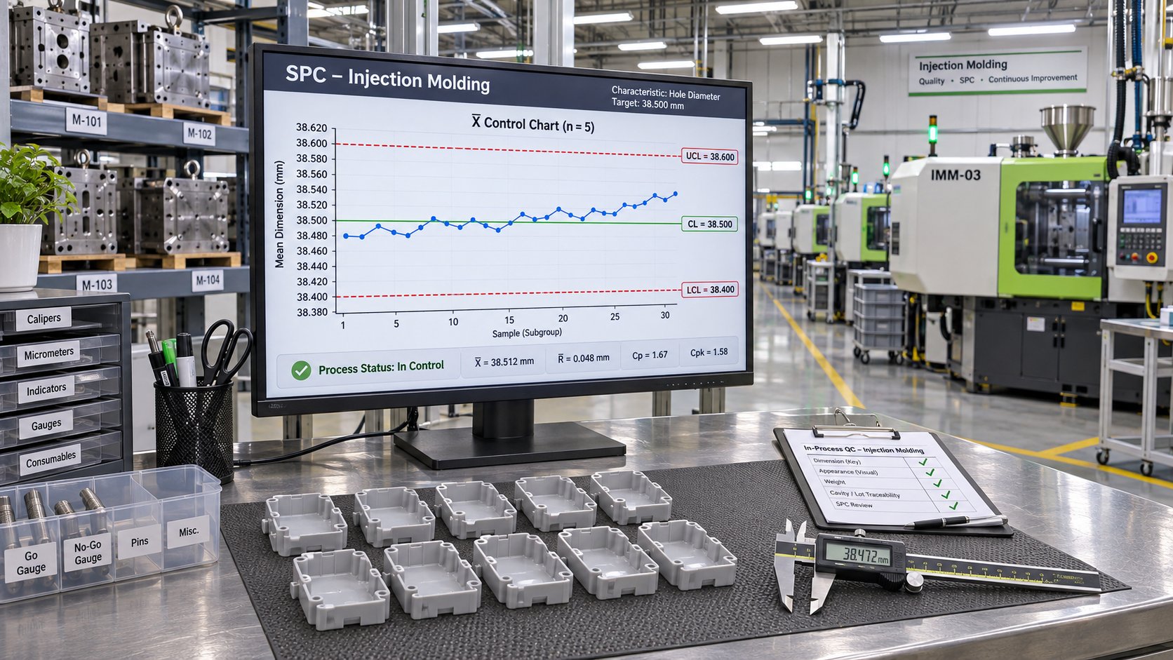
Statistical process control (SPC) turns that invisible creep into something visible, measurable, and actionable — often before a single defective part leaves the cell. Yet despite the importance of cushion in injection molding as a process health indicator, surprisingly few operations track it with the same rigor they apply to part dimensions or cavity pressure. That's a missed opportunity.
Setting Up Cushion as an SPC Variable
Building a meaningful SPC program around cushion starts during process qualification — not after problems appear. The goal is to establish a statistically valid baseline that represents the process running in its known-good state. Here's how that works in practice.
During qualification, record the cushion value for every shot over a statistically meaningful sample. For most injection molding applications, a minimum of 30 to 50 consecutive shots from a stable, thermally equilibrated process provides enough data to calculate a reliable mean and standard deviation. Some validation protocols call for larger datasets — 100 or more shots — especially in regulated environments where the consequences of undetected drift are severe.
From these measurements, you calculate the process mean (X-bar) and standard deviation (sigma). Control limits are then set — typically at three standard deviations above and below the mean for the upper and lower control limits (UCL and LCL). These aren't specification limits or tolerance boundaries. They represent the natural voice of the process: the range within which cushion should fall when nothing has changed. A point outside these limits doesn't necessarily mean a bad part was made — it means something in the process shifted, and that shift demands investigation.
Modern injection molding machines make this easier than ever. Most presses manufactured in the last decade log screw position digitally every cycle, including the end-of-hold cushion value. That data feeds directly into SPC software platforms that chart the values automatically, apply rule-based detection, and flag anomalies in real time. No clipboard rounds, no manual data entry — just continuous, cycle-by-cycle visibility into how the cushion is behaving.
One critical best practice: don't track cushion in isolation. The real diagnostic power emerges when you chart it alongside other key process variables — peak injection pressure, fill time, screw recovery time, and cycle time. This multivariate approach reveals correlations that single-variable monitoring misses. For example, if cushion drifts upward while peak injection pressure rises simultaneously, you're likely looking at a viscosity increase (maybe a cold barrel zone or a material-lot shift). If cushion drops while recovery time stays constant, the check ring may be leaking. These cross-variable patterns turn raw numbers into actionable intelligence.
Research supports this integrated approach. A study published in Polymers demonstrated that monitoring nozzle pressure curves alongside process parameters like the V/P switchover point enabled adaptive systems to reduce product weight variation to a coefficient of variation of just 0.05% — a level of consistency that manual monitoring alone could never sustain. The principle applies directly to cushion: the more variables you correlate, the faster you identify the true source of any drift.
Interpreting Cushion Trends and Alarms
Collecting data is the easy part. Knowing what it's telling you is where SPC earns its keep.
Not all cushion drift looks the same, and different patterns point to fundamentally different root causes. A gradual, steady upward trend tells a completely different story than a sudden step change or a widening scatter band. Learning to read these patterns — the way an experienced physician reads an EKG — is what separates reactive troubleshooting from proactive process management.
SPC methodology distinguishes two types of variation: common-cause variation (the normal, inherent fluctuation within a stable process) and special-cause variation (a signal that something external has changed). Your control chart is designed to separate these. Points dancing randomly within the control limits? That's common-cause — the process is stable. A trend, a shift, or a cluster outside limits? That's special-cause — and it requires action.
Western Electric rules formalize this detection. Beyond the obvious single-point-beyond-3-sigma violation, these rules catch subtler patterns: two of three consecutive points beyond 2-sigma on the same side, four of five points beyond 1-sigma, eight consecutive points on one side of the centerline, or six points in a row steadily increasing or decreasing. Real-time SPC systems apply all eight rules simultaneously to every subgroup, flagging violations within seconds rather than at the end of a shift — when hundreds of suspect parts may have already been produced.
The table below maps the most common cushion trend patterns to their likely root causes and the recommended first-response actions. Think of it as a diagnostic decoder ring for your control chart:
| Cushion Trend Pattern | What It Typically Indicates | Recommended First Response |
|---|---|---|
| Gradual increase (cushion creeping upward over many shots) | Increasing melt viscosity — possibly a cooling barrel zone, material-lot viscosity shift, or moisture pickup in hygroscopic resin; also possible check-ring leakage reducing effective injection stroke | Verify barrel zone temperatures; check material drying conditions; compare material lot data; perform a check-ring seal test if temperature and material are confirmed normal |
| Gradual decrease (cushion slowly shrinking) | Decreasing melt viscosity — potentially an overheating barrel zone or degraded material lowering viscosity; also possible that hold pressure is compressing a softening melt column further forward | Inspect barrel heater band function; verify melt temperature with a pyrometer; review regrind percentage for changes; check that decompression (suck-back) settings haven't been altered |
| Sudden shift upward (abrupt step change to higher cushion) | Acute process disruption — a temperature controller failure dropping a zone offline, a new material lot with higher viscosity, a gate blockage restricting flow, or a hydraulic pressure change | Immediately check all barrel zone actual vs. setpoint temperatures; verify material hopper for lot change or contamination; inspect nozzle and hot-runner gates; review hydraulic pressure readings |
| Sudden shift downward (abrupt drop to lower cushion) | Loss of melt volume or seal — a cracked or stuck check ring allowing sudden backflow, a nozzle drool event losing material, or an accidental shot-size change | Verify shot-size setting matches recipe; check for nozzle drool or sprue sticking; perform an immediate check-ring seal test; inspect for material bridging in the feed throat |
| Increasing scatter (widening shot-to-shot variation without a clear directional trend) | Inconsistent check-ring sealing — the ring is closing differently on each shot, often due to wear, contamination, or a damaged seat surface; also possible feed-throat disruption causing inconsistent screw recovery | Prioritize a check-ring seal test; inspect the feed throat for bridging or blockage; verify back-pressure consistency; if scatter persists after confirming process settings, schedule screw pull for hardware inspection |
Notice a recurring theme in the table: many root causes trace back to the check ring, barrel temperatures, and material condition. That's not coincidence — these are the three systems most directly responsible for delivering a consistent melt volume to the screw tip each cycle. When any one of them wavers, the cushion is usually the first variable to show it.
The practical value of this monitoring approach compounds over time. As you accumulate weeks and months of cushion data on a particular mold-and-machine combination, you build a historical profile. You'll notice, for instance, that a high cushion position in plastic injection molding on this specific tool always correlates with a particular barrel zone reading two degrees below setpoint. Or that cushion scatter increases predictably every 50,000 shots as the check ring wears. These patterns become your early-warning system, letting you schedule maintenance proactively instead of reacting to failures.
A well-maintained SPC program also changes the nature of shift handoffs. Instead of verbal descriptions like "the process seemed a little off last night," the incoming operator sees a control chart with a clear trend — objective, quantifiable, and immune to interpretation bias. That visibility makes the difference between catching a drift at cycle 50 and catching it at cycle 500.
Yet even the best monitoring system only tells you that something changed. Figuring out what changed — and fixing it systematically rather than by trial and error — requires a structured root-cause framework that separates mechanical failures from material shifts from process-setting errors. That diagnostic discipline is where cushion troubleshooting moves from art to engineering.
Troubleshooting Inconsistent Cushion with a Root-Cause Framework
Your SPC chart flagged an out-of-control condition. Cushion is drifting, scattering, or has shifted abruptly. You know something changed — but what? This is the moment where most troubleshooting efforts go sideways. An operator tweaks shot size. A setup tech bumps hold pressure. A supervisor suggests pulling the mold. Each adjustment masks the real problem while potentially introducing new ones, and the unstable cushion injection molding condition persists or returns within hours.
Effective diagnosis requires a structured approach — not guesswork. Cushion problems originate from three distinct categories of root causes: mechanical failures, material changes, and process-setting errors. These categories don't overlap randomly. They follow a diagnostic hierarchy that, when worked in the right order, isolates the true cause efficiently and prevents unnecessary hardware replacements or mold pulls.
Mechanical Root Causes of Cushion Problems
If your injection molding machine has no cushion — or cushion that wanders unpredictably from shot to shot — the first suspect on your list should be the check ring.
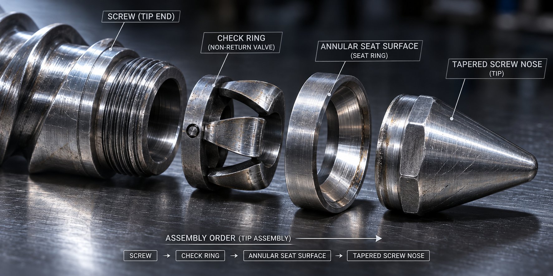
The check ring (non-return valve) sits at the tip of the screw and has one critical job: seal completely during injection to prevent melt from flowing backward past the screw tip. When the screw pushes forward, the ring slides rearward against its seat, closing off the flow channels. This seal is what allows the melt column ahead of the screw to transmit hold pressure into the cavity. A worn or damaged check ring compromises that seal, and as Asaclean's processing experts explain, "one telltale sign you have a leaking or worn non-return valve is the machine losing its injection cushion and ability to apply plastic pressure."
What does a leaking check ring actually do to cushion behavior? During injection, melt slips backward past the worn seat surfaces instead of being driven entirely into the cavity. The screw creeps farther forward than it should — consuming the cushion — because part of the melt volume is escaping in the wrong direction. Shot-to-shot, the amount of leakage varies depending on melt viscosity, injection speed, and how the ring happens to seat on each cycle. The result is a cushion reading that jumps around erratically, even when every process setting on the controller remains locked.
Two diagnostic methods help you confirm whether the check ring is the culprit before pulling the screw:
- Screw-slip test (injection seat test): With the screw in the forward position and the nozzle seated against the sprue bushing (or a purge cap), apply injection pressure without screw rotation. Monitor the screw position. On a properly sealing check ring, the screw should hold its position or move forward only minimally. If the screw creeps forward steadily — losing position over 10-30 seconds — melt is leaking past the ring, and the seal has failed.
- Decompression-hold test: After screw recovery, apply a small decompression (suck-back) and then hold the screw stationary for 30-60 seconds without injecting. Measure the screw position before and after. If the position changes significantly, material is migrating past the check ring under residual barrel pressure. A healthy valve shows minimal or no positional drift.
Beyond the check ring itself, two other mechanical culprits contribute to backflow and cushion loss over time. Barrel bore wear increases the clearance between the screw flight outer diameter and the barrel wall, creating a secondary leakage path that allows melt to flow rearward along the screw channels instead of being pushed forward. Screw-flight wear — particularly on the metering section — reduces pumping efficiency and can alter the effective shot volume delivered to the front of the barrel during recovery. Both conditions worsen gradually, which is why they often appear as a slow downward cushion trend on SPC charts rather than an abrupt shift.
Hunter Plastics reinforces this connection: "Check-ring, screw, or barrel wear can affect shot consistency. If cushion, recovery time, injection time, and part weight start changing together, your injection unit deserves a closer look." That correlation — multiple indicators drifting simultaneously — is the hallmark of mechanical wear, as opposed to a single-variable shift caused by a material or process-setting change.
Material and Process-Setting Root Causes
Not every reason for cushion variation in injection molding traces back to worn hardware. Material-side issues and incorrect process settings can produce identical symptoms — and they're far cheaper to fix if you identify them first.
Material issues alter how the melt behaves inside the barrel, which directly changes screw recovery, check-ring sealing dynamics, and the resulting cushion:
- Moisture in hygroscopic resins: Resins like nylon, PBT, PC, and PMMA absorb atmospheric moisture. Undried or improperly dried material enters the barrel with water molecules that vaporize at processing temperature, reducing melt viscosity and generating gas. The lower viscosity allows more backflow past the check ring, dropping the cushion. The gas pockets create compressibility that makes the cushion reading erratic. Avient's troubleshooting guide lists moisture-related silver streaking and splay as direct consequences of contaminated material entering the barrel.
- Regrind percentage variation: Regrind typically has different bulk density, pellet geometry, and melt-flow characteristics than virgin resin. Changing the regrind ratio — even unintentionally, through inconsistent blending — alters how the screw feeds and plasticizes material. The result is shot-to-shot density differences that show up as cushion scatter.
- Material-lot viscosity shifts: Resin manufacturers produce within a melt-flow-index (MFI) specification range, not at an exact target. A new lot that falls at the upper or lower boundary of that range can shift screw recovery behavior enough to alter cushion by several tenths of a millimeter — a subtle but measurable change that may push a tight process outside its control limits.
Process-setting errors are the most straightforward to verify and correct, which is why they belong at the top of your diagnostic sequence — check them first before investigating anything more invasive:
- Incorrect decompression (suck-back): Excessive decompression after screw recovery pulls air into the melt column, introducing compressibility that changes how the cushion behaves during injection. Too little decompression can cause nozzle drool, losing melt volume and reducing the effective cushion.
- Improper back pressure: Back pressure during screw recovery affects melt homogeneity and density. Too low, and the melt contains voids and inconsistent density. Too high, and excessive shear heating raises melt temperature beyond target, reducing viscosity and altering check-ring dynamics.
- Barrel temperature errors: A failed heater band, a thermocouple reading incorrectly, or a controller zone set to the wrong value can shift melt viscosity in one section of the barrel. The resulting inhomogeneous melt produces cushion variation that looks random on the SPC chart but correlates tightly with the malfunctioning zone.
- Shot-size miscalculation: If the shot size was set incorrectly during mold setup — or if it was changed inadvertently — the screw recovery position shifts, directly altering how much material is available and where the cushion lands after hold.
Jumping straight to a screw pull when the cushion drifts wastes hours of production time if the real cause is a damp batch of nylon or a heater band reading ten degrees low. A disciplined diagnostic sequence prevents that kind of costly misdiagnosis. Follow this order:
- Verify process settings match the documented recipe: Compare every active parameter — shot size, transfer position, hold pressure, hold time, decompression, back pressure, barrel temperatures, and screw RPM — against the original setup sheet. Any deviation gets corrected before further investigation.
- Check material condition: Confirm the resin lot number, verify dryer performance (dew point, temperature, residence time), and check the regrind blend ratio. If material changed recently, that's your prime suspect.
- Perform a check-ring seal test: Run the screw-slip test described above. If the ring seals properly, mechanical wear is unlikely to be your root cause — move on. If leakage is detected, you've found your problem.
- Inspect screw and barrel wear: If the check ring passes but cushion issues persist, measure the barrel bore with a bore gauge and inspect screw flights for wear, scoring, or buildup. Clearances exceeding OEM specifications indicate that hardware replacement is necessary.
- Evaluate nozzle and hot-runner components: A partially blocked nozzle tip, a worn nozzle seat, or a malfunctioning hot-runner valve gate can restrict or alter melt flow in ways that change the effective cushion. These are often overlooked because they sit outside the barrel, but they directly influence how pressure transmits from the screw to the cavity.
This ordered approach works because it moves from the fastest and cheapest checks (settings and material) to the most time-consuming (hardware inspection), ensuring that you don't tear down equipment for a problem that could have been solved by verifying a barrel temperature setpoint or checking a dryer dew-point reading. Each step either eliminates a category of root causes or confirms it, narrowing your search systematically until only the true cause remains.
Of course, when the diagnostic sequence does arrive at step four — and the data confirms that mechanical wear is driving your cushion instability — the question shifts from what's wrong to what needs to be replaced. That's where understanding exactly how check-ring erosion, barrel bore enlargement, and screw-flight degradation undermine even perfectly optimized process settings becomes essential.
Check-Ring and Screw-Barrel Wear Effects on Cushion Control
Your diagnostic sequence confirmed it: process settings are correct, material condition checks out, and the check-ring seal test showed leakage. Or maybe the bore gauge revealed clearances well beyond tolerance. Either way, you've landed on a hardware problem — the kind that no amount of parameter tweaking can compensate for. This is the reality that many molders resist accepting, because it means downtime, parts sourcing, and a screw pull. But continuing to run on worn plasticizing components is like trying to hold water in a cracked bucket. You can pour faster, but you'll never fill it.
Understanding exactly how each component fails — and recognizing the warning signs before cushion instability becomes a quality crisis — is what separates a planned maintenance event from an emergency shutdown.
Check-Ring Wear and Cushion Loss Diagnosis
The check ring must create a complete, repeatable seal every single cycle. During injection, the ring slides backward against a precision-machined seat on the screw tip, blocking the melt channel so that all forward pressure transmits into the cavity. That seal is what maintains your injection molding cushion. When the sealing surfaces degrade, so does the cushion — and the degradation is rarely sudden.
Worn seat surfaces develop micro-channels that allow melt to creep past during injection. Cracked rings lose structural integrity and can tilt or hang open intermittently. Damaged or eroded screw tips no longer provide a flat, uniform mating surface for the ring to close against. Each of these conditions permits backflow — melt escaping rearward over the screw flights instead of being driven into the mold. The screw advances farther than it should to compensate, consuming the cushion unpredictably from shot to shot.
What accelerates this wear depends heavily on what you're running through the barrel. Abrasive fillers are the primary mechanical aggressor. Glass-fiber-reinforced nylon, mineral-filled polypropylene, and glass-bead-loaded compounds act like fine sandpaper on every metal surface they contact. Plastics Technology reports that abrasive fillers cause the most severe wear in high-pressure zones, and the check-ring seat is one of the highest-pressure contact points in the entire plasticizing assembly. The amount of filler and particle geometry matter significantly — larger particles with sharp corners wear surfaces faster than smaller, rounder alternatives.
Corrosive resins attack from a different angle. PVC releases hydrochloric acid at elevated temperatures. Flame-retardant compounds can generate halogenated gases that chemically erode steel surfaces. Industry guidance on check-ring metallurgy confirms that when corrosion is the primary failure mode, selecting a corrosion-resistant steel grade matters more than maximizing hardness — because even the hardest ring won't survive chemical attack on its sealing faces. For standard unfilled resins, nitrided tool steel typically provides adequate life. For glass-filled compounds, powder metallurgy high-speed steels offer measurably longer service. And for corrosive materials, specialized corrosion-resistant grades become essential despite their lower abrasion resistance.
So how do you know when to act? If your SPC charts show cushion variation exceeding control limits — and you've already confirmed that process settings and material condition are correct using the diagnostic sequence from the previous section — a check-ring seal test becomes the decisive next step. Run the screw-slip test: apply injection pressure with the screw held stationary and the nozzle seated. If the screw creeps forward steadily over 10 to 30 seconds, you have confirmed backflow. At that point, pulling the screw to inspect the check ring, seat surfaces, and tip is no longer optional — it's the only path to restoring cushion stability.
When Screw and Barrel Replacement Restores Cushion Stability
The check ring gets most of the attention because it's the most common failure point. But it doesn't operate in isolation. The ring seals against surfaces machined on the screw tip, and the ring's outer diameter rides within the barrel bore. When either of those mating components wears beyond tolerance, replacing the ring alone won't solve the problem.
Barrel bore wear is measured with a bore gauge — a straightforward measurement that compares the current internal diameter to the original OEM specification. As Adams Engineers explains, recording bore measurements at regular intervals creates a wear profile that predicts when replacement will be necessary, transforming maintenance from reactive to planned. When the bore diameter exceeds tolerance, the clearance between the screw flight OD and the barrel wall grows large enough that melt leaks backward along the screw channels during injection — a secondary backflow path that no check ring, however perfect, can prevent.
Screw-flight wear compounds the problem. Research published in Plastics Technology shows that a common rule of thumb considers a flight clearance four times the original tolerance to be the cutoff for replacement, though resin viscosity matters — higher-viscosity materials tolerate more clearance before leakage becomes critical, while low-viscosity resins like polypropylene show significant output loss at smaller clearance increases. As radial clearance grows, the screw loses pumping efficiency. Recovery becomes inconsistent. The melt delivered to the front of the barrel varies in volume and temperature from shot to shot. And the cushion — sitting downstream of all these failures — reflects every one of them.
At a certain point, the math simply doesn't work. You can optimize every process setting on the controller, dry the resin perfectly, and set the transfer position to within a hundredth of a millimeter — but if the barrel bore is oversized and the screw flights are worn down, melt will leak, shots will vary, and how to fix minimum cushion injection mold problems through process adjustment alone becomes impossible. Hardware replacement is the corrective action.
For operations where cushion instability traces back to worn plasticizing components, the replacement hardware needs to match more than just dimensional specifications. The screw geometry, metallurgy, and wear-resistance characteristics must align with the specific machine, resin, and shot-size requirements — otherwise the new components may wear prematurely or fail to deliver the melt quality needed for stable cushion control. NANHAIYA's custom injection molding screw barrels are engineered around this principle, with a technical review that evaluates screw geometry, wear resistance, melting efficiency, mixing performance, and material-retention behavior to match each replacement to the application. Rather than supplying a generic catalog part, this approach ensures the new screw and barrel restore proper melt sealing and the cushion consistency that depends on it.
Knowing how to set cushion in injection molding correctly is only half the equation — the hardware behind that setting must be capable of delivering it. The following indicators signal that your plasticizing components have crossed the threshold where process optimization alone can no longer compensate:
- Declining cushion consistency despite process optimization: If you've verified settings, material, and check-ring seal and the cushion still won't stabilize, barrel or screw wear is the remaining variable.
- Visible scoring on screw flights: Deep grooves, galling marks, or chipped hardfacing on the flight OD indicate that the screw has lost its ability to maintain a tight seal against the barrel wall.
- Bore-gauge measurements exceeding OEM tolerance: Any measurement showing diametrical clearance beyond the manufacturer's specified limit confirms that the barrel can no longer contain melt flow within designed parameters.
- Increased screw-recovery time: A screw that takes progressively longer to recover the same shot size is losing pumping efficiency — either through flight wear reducing forward conveyance or through barrel clearance allowing rearward leakage during rotation.
- Simultaneous drift in cushion, shot weight, and recovery time: When multiple indicators move together, the common denominator is almost always the plasticizing hardware. Individual settings or material changes rarely affect all three in parallel.
Treating the screw and barrel as controlled wearing components — rather than permanent fixtures you inspect only during emergencies — is the mindset that sustains long-term cushion stability. Regular measurement, documented wear trends, and planned replacement intervals keep the hardware within the tolerances your process depends on. And for molders operating in regulated industries, that same hardware condition directly determines whether the process stays within its validated cushion range — a compliance requirement that carries consequences far beyond a single rejected batch.
Cushion Documentation in Process Validation and Regulated Manufacturing
In a typical custom molding shop, a drifting cushion triggers a process adjustment and the shift moves on. In a medical device or automotive safety-critical program, that same drift can trigger a formal investigation, a deviation report, and potentially a partial revalidation costing tens of thousands of dollars. The difference isn't the physics — the melt behaves identically regardless of what industry the part serves. The difference is documentation. In regulated manufacturing, the injection molding cushion process validation record is auditable evidence that the process remains under control, and gaps in that record carry regulatory consequences.
Yet across most injection molding resources, cushion is discussed purely as a process optimization variable — something to dial in and monitor for quality. The compliance dimension is almost entirely absent. For validation engineers, quality managers, and anyone supplying molded components into FDA-regulated or IATF 16949 environments, that's a significant blind spot.
Cushion Ranges in IQ OQ PQ Protocols
Imagine you're qualifying a new mold for a Class II medical device. The validation plan calls for Installation Qualification, Operational Qualification, and Performance Qualification — the structured three-phase method the FDA expects for processes whose results can't be fully verified by final inspection alone. Where does cushion fit into each phase?
During IQ, the focus is readiness. The press, mold, peripherals, and utilities are confirmed to be installed and configured per specification. Cushion doesn't receive its own acceptance criteria at this stage, but the groundwork matters: the machine's ability to log and display screw position data is verified, controller software version is documented, and the recipe storage system that will hold the validated cushion target is confirmed operational. Think of IQ as making sure the instrument can read the measurement before you trust any readings.
During OQ, cushion becomes a directly evaluated parameter. This is where process characterization studies — often structured as a design of experiments (DOE) or high-low boundary study — challenge key variables to determine which parameter ranges produce acceptable parts. Validation engineers vary fill speed, transfer position, pack pressure, hold time, melt temperature, mold temperature, and cooling time across their tested boundaries. Throughout these studies, cushion is recorded alongside part dimensions, weights, and visual attributes.
The critical output of OQ isn't just the nominal cushion value — it's the proven acceptable range. By running the process at its boundary conditions and confirming that parts still meet critical-to-quality (CTQ) requirements, the team establishes the widest window within which cushion can vary without jeopardizing part conformance. Then — and this is the step that separates robust validation from fragile documentation — they set the validated operating limits tighter than the full capability window. This safety margin ensures that normal production variation stays well inside the boundaries where parts are known to be acceptable, providing early warning before quality is at risk.
For example, if OQ studies show that parts meet all CTQ requirements with cushion values between 2.5 mm and 7.0 mm, the validated operating range might be set at 3.5 mm to 6.0 mm. The alarm limits on the press — the thresholds that trigger an operator alert or automatic cycle stop — sit within or at these boundaries. Any shot producing a cushion outside that range gets flagged immediately, not discovered during a post-production audit.
During PQ, the process runs at production cadence under normal conditions — real operators, real material lots, real shift changes. Cushion data collected during PQ confirms that the values established in OQ hold up in the routine manufacturing environment. PQ sampling typically spans multiple runs, shifts, and sometimes material lots to demonstrate that the cushion specification for injection molding quality remains stable across the variability sources the process will encounter in ongoing production. As Kaysun's validation framework describes it, PQ proves the process performs under conditions that reflect real manufacturing — not a carefully controlled engineering demo.
Maintaining Cushion Compliance Over Production Life
Passing PQ isn't the finish line. It's the starting point for a monitoring obligation that lasts as long as the validated process runs.
The SPC control charts discussed earlier in this article serve double duty in regulated environments. They're not just process optimization tools — they're validation compliance records. Every cushion data point logged during production becomes part of the documented evidence that the process remains within its qualified state. When an auditor reviews the process file six months or two years after PQ, those charts demonstrate continuity. They show that the cushion didn't just pass qualification on a good day — it stayed within limits across thousands of production cycles.
Drift outside the validated window changes the conversation entirely. A cushion reading that exceeds the qualified range doesn't just warrant a process adjustment — it triggers a formal deviation investigation. The quality team must determine whether affected parts are conforming, whether the root cause is identified and corrected, and whether the deviation undermines confidence in the validated state. Depending on the severity and duration of the excursion, the outcome may require disposition of suspect inventory, a corrective action, or — in the most consequential cases — a partial or full revalidation.
This is precisely where the hardware discussion from the previous section intersects with regulatory compliance. When check-ring wear or barrel bore enlargement causes cushion to drift progressively outside qualified limits, replacing the worn components is only the first step. After installing the new screw and barrel, the process must be confirmed — through documented runs and data — to be operating within the original validated range. Depending on the scope of the hardware change and the program's risk level, this confirmation may require a partial revalidation: re-executing portions of OQ to verify the process window still holds with the new components, followed by a condensed PQ to confirm production stability. FDA expectations explicitly call for revalidation when changes or deviations affect critical process inputs — and a worn-out plasticizing assembly that can no longer maintain cushion within specification clearly meets that threshold.
In regulated manufacturing, the injection molding cushion is not just a process optimization variable — it is a documented quality attribute subject to audit, with validated limits that must be maintained, monitored, and defended throughout the product's production life.
Change control discipline ties everything together. Any modification that could affect cushion behavior — a resin supplier change, a mold revision that alters flow or packing, a press transfer, even a shift in regrind policy — must be evaluated against the validated process before implementation. The question isn't whether the change seems minor. The question is whether it could move the cushion outside the range that was proven during OQ and confirmed during PQ. If the answer is yes, or even uncertain, the change requires formal evaluation and documented approval before production resumes.
For medical device and automotive quality teams, this regulated injection molding cushion documentation framework transforms a single process variable into a traceable quality record. It connects the physics of melt behavior to the paperwork that supports regulatory submissions, customer audits, and production release decisions. And it ensures that when someone asks — months or years from now — whether the process was in control, the data exists to prove it.
Frequently Asked Questions About Injection Molding Cushion
1. What is cushion in injection molding and why does it matter?
Cushion refers to the small volume of molten plastic remaining in front of the screw tip at the end of the hold phase. It acts as the hydraulic medium that transmits pack and hold pressure from the screw into the mold cavity. Without adequate cushion, the screw bottoms out against the barrel end cap and can no longer deliver pressure to compensate for volumetric shrinkage as the part cools. This results in short shots, sink marks, and unpredictable dimensional variation. Maintaining a stable cushion ensures consistent packing, uniform part weight, and repeatable quality across production runs.
2. What is the ideal cushion size for injection molding?
Industry literature commonly cites 3-6 mm (0.125-0.25 in) as a general starting range, but the ideal value depends on several application-specific factors. Screw diameter is critical because the same linear cushion represents vastly different melt volumes on different machines — 4 mm on a 25 mm screw holds roughly 1.96 cm3, while the same distance on a 90 mm screw holds about 25.4 cm3. Shot size as a percentage of barrel capacity, resin type (semi-crystalline vs. amorphous), part wall thickness, and required hold pressure all influence the optimal target. Always recalculate when transferring a mold to a different press rather than copying the linear value.
3. What causes inconsistent cushion in injection molding?
Inconsistent cushion typically stems from three root-cause categories. Mechanically, a worn or damaged check ring (non-return valve) is the most common culprit — it allows melt to leak backward past the screw tip during injection, reducing cushion unpredictably each shot. Barrel bore wear and screw-flight degradation create secondary leakage paths. On the material side, moisture in hygroscopic resins, regrind ratio changes, and lot-to-lot viscosity shifts all alter melt behavior and cushion stability. Process-setting errors such as incorrect decompression, improper back pressure, or barrel temperature deviations round out the list. A structured diagnostic sequence — verifying settings first, then material, then hardware — isolates the true cause efficiently.
4. How does the velocity-to-pressure switchover affect cushion?
The V/P switchover point determines how much melt remains in front of the screw when the machine transitions from speed-controlled filling to pressure-controlled packing. A late transfer means the screw travels too far forward during fill, leaving a dangerously thin cushion that risks bottoming out during hold. An early transfer preserves plenty of cushion but leaves the cavity short-filled, and pack pressure alone typically cannot complete the fill. Scientific molding practitioners generally aim to fill 95-98% of the cavity during the velocity phase, reserving only final volumetric compensation for the pressure-controlled stages, which naturally produces a well-balanced cushion.
5. When should the screw and barrel be replaced to restore cushion stability?
Replacement becomes necessary when process optimization and material verification can no longer compensate for hardware wear. Key indicators include declining cushion consistency despite confirmed-correct process settings, bore-gauge measurements exceeding OEM tolerance, visible scoring or galling on screw flights, progressively increasing screw-recovery time, and simultaneous drift in cushion, shot weight, and recovery time. For best results, replacement components should be matched to the specific machine, resin, and shot-size requirements. Custom-engineered screw barrels — such as those from NANHAIYA, which undergo a technical review covering geometry, wear resistance, melting efficiency, and mixing performance — help ensure the new hardware restores proper melt sealing and long-term cushion control.
Written by
Nanhaiya Technical Team
Zhoushan Nanhaiya Plastic Machinery Co., Ltd.
The Nanhaiya technical team supports screw and barrel manufacturing projects through application review, technical communication, custom manufacturing coordination, and production and quality control.
Discuss Your Application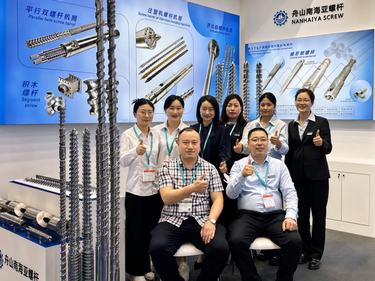
Related Articles
More insights on screw barrel technology and plastics processing.
Still Chasing Black Specks? Purging Plastic Needs a Full Rethink
Nov 6, 2026
Learn how purging plastic cuts scrap, downtime, and rejects. Compare all purging methods, match compounds to resins, and build a preventive program that works.
Read Article
Stop Chasing Symptoms: Fix Injection Molding Splay at the Source
Nov 6, 2026
Learn what causes injection molding splay, how to diagnose moisture, shear, and degradation splay by location, and fix silver streaks at the root cause.
Read Article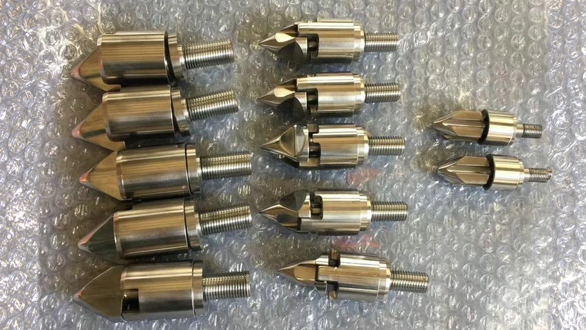
Injection Molding Screw Tip: How Hidden Wear Triggers Costly Defects
Nov 6, 2026
Learn how injection molding screw tip wear causes defects like short shots and black specks. Covers tip types, material selection, installation, and replacement.
Read ArticleLooking for something else?
Search by material, symptom or product and jump straight to the relevant page.
These are navigation suggestions based on keyword matching — not a quotation, not a delivery commitment, and not a substitute for engineering review. Final specification is confirmed by our engineers against your drawings and processed material.
Need help with screw barrel selection?
Share your machine model, processed material and application. Our team can help with pricing and technical support.