

What Is Splay in Injection Molding?
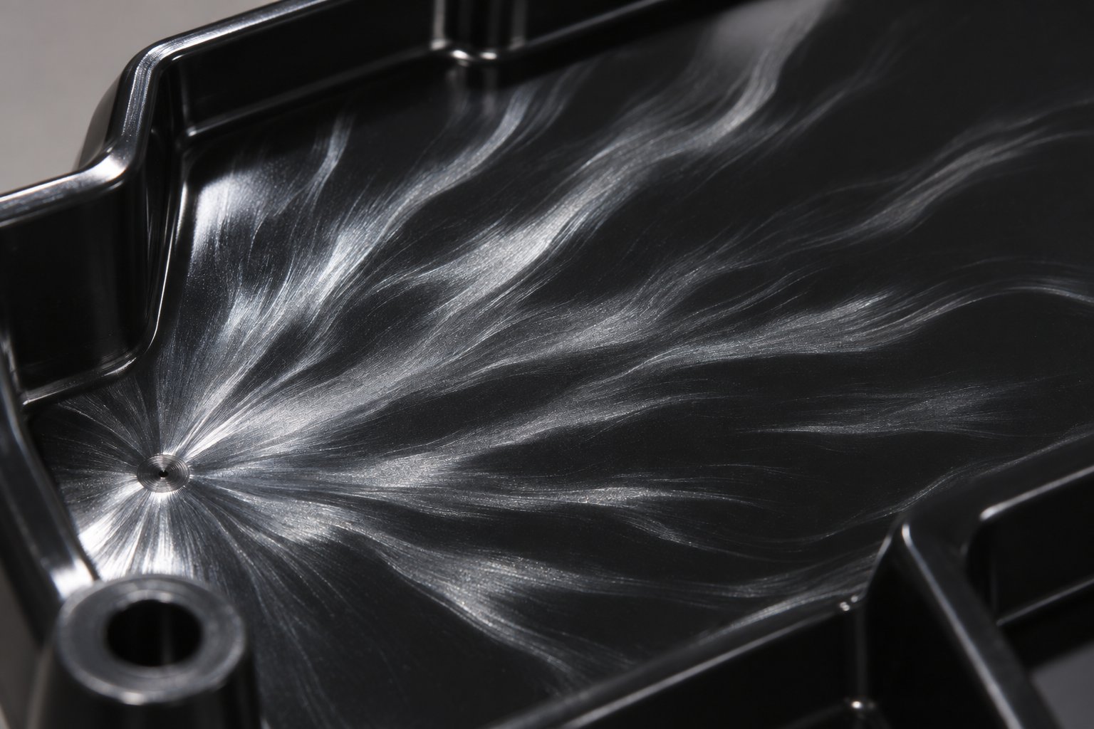
You pull a freshly molded part off the press, and there they are — silvery, flame-shaped streaks fanning outward from the gate across what should be a flawless surface. If you've spent any time on an injection molding floor, you'll recognize the defect instantly. But do you know what it's really telling you?
Splay Defined in Plain Language
Injection molding splay is a surface defect characterized by silver or whitish streaks that radiate outward from the gate along the direction of melt flow. It is caused by trapped gas — originating from moisture, thermal degradation, or shear — breaking through the melt front and stretching across the mold wall during cavity filling.
The defect goes by several names in the industry. You may hear it called silver streaks, silver splash, or simply splay marks. Regardless of the label, the visual signature is consistent: directional, elongated streaks that always align with the path the molten plastic traveled as it filled the cavity. They look almost like tiny flames or splashes frozen into the part surface.
Splay is most visible on glossy or dark-colored parts, where even a faint silver streak stands out sharply against the surrounding finish. On textured or light-colored surfaces, it can be subtler — and easier to miss during a quick visual inspection. That subtlety is part of what makes it dangerous. The streaks themselves are actually elongated gas or moisture bubbles that were dragged across the surface during injection, leaving behind a disrupted layer of polymer on the outermost skin of the part.
Why Splay Matters Beyond Cosmetics
It's tempting to treat splay in injection molding as a purely aesthetic issue — something that only matters when the customer demands a Class A finish. That assumption is risky. Those silver streaks are physical evidence that something went wrong inside the melt stream, and the consequences often extend well below the surface.
When the gas behind splay comes from polymer degradation, the affected zone has experienced chain scission — the molecular chains that give plastic its strength have literally broken apart. This means the part may also suffer from reduced impact strength, lower elongation at break, and compromised long-term durability, even if it passes a dimensional check. As industry sources note, a part with splay typically indicates the material's molecular structure has been compromised, making it a potential structural concern for high-stakes applications like automotive and medical components.
Here's the key insight most troubleshooting guides miss: randomly adjusting barrel temperatures, injection speeds, and back pressure might make splay disappear on one cycle and reappear on the next. Understanding the defect at a scientific level — why the gas formed, where it entered the melt, and how it reached the surface — is the fastest path to a permanent fix.
That's exactly the approach this article takes. Rather than handing you a generic checklist, the sections ahead walk through a root-cause diagnostic framework: from the physics of how splay forms, to a systematic decision tree for isolating the specific gas source, to material-specific drying parameters and hardware considerations that most resources overlook entirely. The goal is to help you stop chasing symptoms and start eliminating the source.
The Science Behind Splay Formation
Splay never appears without a reason. Every silver streak on a molded part traces back to a gas bubble that had no business being inside the melt stream. The real question — and the one that separates a permanent fix from a temporary band-aid — is where that gas came from. Three distinct mechanisms account for virtually every case of splay in plastic injection molding, and each one leaves its own fingerprint on the part.
How Gas Enters the Melt Stream
1. Moisture vaporization. Hygroscopic resins like polycarbonate, nylon, PET, and ABS absorb water molecules from the surrounding atmosphere. Those trapped water molecules remain harmless at room temperature, but imagine what happens when wet pellets enter a barrel heated well above 100 °C. The water flashes to steam almost instantly, generating pockets of vapor that become dispersed throughout the melt. Even small amounts of excess moisture — sometimes as little as 0.02% by weight in PET — can produce enough steam to riddle a part with injection molding splay marks. Research conducted at the American Injection Molding Institute demonstrated that PET molded with elevated moisture content experienced catastrophic degradation even at low melt temperatures and short residence times, confirming just how aggressively moisture drives both splay and molecular weight loss in hydrolyzable resins.
2. Thermal degradation. When polymer chains are exposed to excessive heat, prolonged residence time in the barrel, or intense shear forces, the covalent bonds along the molecular backbone begin to break — a process known as chain scission. This breakdown releases volatile byproducts directly into the melt. The specific gases depend on the resin: polycarbonate releases CO₂ and bisphenol-A vapors, polystyrene releases styrene monomer, and acetal (POM) can produce formaldehyde. As Beaumont Technologies points out, a processor's number one responsibility is to preserve the molecular weight of the polymer during molding — because once those chains break, the volatiles they release become the gas source behind degradation splay. The risk compounds quickly: higher melt temperature combined with longer barrel residence time doesn't just add degradation, it multiplies it.
3. Entrained air. During screw recovery, the rotating screw pulls resin forward while air can be drawn into the channel between pellets. Normally, the compression zone of the screw squeezes most of that air back out. But if the screw decompression (suck-back) setting is too aggressive, a vacuum forms at the nozzle tip and pulls ambient air directly into the melt. That trapped air pocket rides into the cavity on the very next shot. Unlike moisture or degradation gases, entrained air doesn't involve any chemical reaction — it's simply atmospheric gas in the wrong place at the wrong time.
Fountain Flow and Streak Formation
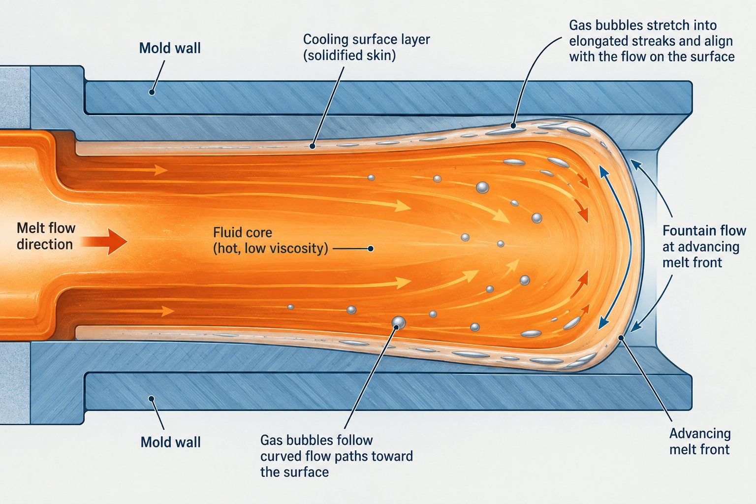
Understanding what is splay in injection molding also means understanding how a gas bubble becomes a visible streak. The answer lies in a phenomenon called fountain flow.
Picture a wave breaking on a beach. As molten plastic enters the mold cavity, the melt front doesn't push forward like a piston. Instead, material at the center of the flow channel moves fastest, reaches the front, then rolls outward toward the cavity walls — much like water curling over at the crest of a wave. This rolling, outward-spreading motion is fountain flow, and it's the mechanism that transports gas bubbles from deep within the melt stream to the part surface.
Research on bubble behavior during mold filling confirms this model. A study published in Polymer Engineering & Science found that bubbles formed during filling produce oriented, deformed shapes because they are stretched along the direction of flow. As these bubbles reach the melt front, fountain flow pushes them against the cooler cavity wall, where they are flattened, elongated, and frozen into the solidifying skin. The result is the characteristic silver streaks you see on the finished part — each one a fossilized gas bubble stretched thin across the surface.
This stretching mechanism explains a critical diagnostic trait: splay always aligns with the melt-flow direction. If the streaks on your part don't follow flow vectors, you're likely looking at a different defect entirely.
Matching the Gas Source to the Visual Clue
Each gas-generation mechanism tends to leave a slightly different pattern on the part. Recognizing these differences is the first step toward narrowing down the root cause before you touch a single process parameter:
- Moisture splay — Tends to appear broadly across the part, often concentrated near the gate where the wet melt first contacts the cavity wall. Streaks are typically numerous and uniformly distributed. Drying a small resin sample and remolding is the fastest confirmation test.
- Thermal degradation splay — Often appears further downstream from the gate or worsens progressively over consecutive cycles as degraded material accumulates in the barrel. The streaks may have a slightly yellowish or brownish tint in light-colored resins, signaling oxidation or charring alongside the gas release.
- Entrained air splay — Usually shows up as a concentrated burst of silver right at the gate, particularly on the first portion of the shot. It can be intermittent from cycle to cycle. Reducing the screw decompression distance is the quickest way to test this theory.
Every splay streak is a gas bubble's autobiography — its location, shape, and timing tell you exactly where the gas originated and why.
With this framework in place — three gas sources, one flow mechanism, and distinct visual signatures — the next logical step is a structured method for testing each possibility without the confusion of changing multiple variables at once.
A Systematic Decision Tree for Diagnosing Splay Root Causes
Knowing that moisture, degradation, and entrained air each leave different fingerprints on a molded part is valuable — but only if you have a reliable method for testing each suspect one at a time. Most troubleshooting guides hand you a laundry list of possible causes and leave you to guess which one applies. That approach burns hours, wastes resin, and often leads to overcorrecting one variable while accidentally introducing another problem.
A better strategy? Treat the splay defect in injection molding like a process engineer would treat any unknown: run a controlled elimination sequence. The flowchart below walks you through that sequence step by step, starting with the most common culprit and working toward the less obvious ones. Each step requires only one change, one remold, and one observation before you move on.
Step-by-Step Splay Diagnostic Flowchart
Follow this decision tree in order. Resist the urge to skip ahead — the sequence is designed so that each test rules out one root cause cleanly before the next variable is introduced.
- Test for moisture first. Pull a small batch of resin from your hopper and dry it thoroughly in a lab oven at the resin manufacturer's recommended temperature and time (or slightly longer for safety). Remold using only this verified-dry material. If the splay marks disappear, you've confirmed moisture as the root cause. Stop here — your corrective action is fixing the drying process, not adjusting machine parameters. As Jeek Mould's engineering team notes, moisture is overwhelmingly the dominant cause of splay, making this the highest-probability starting point.
- If splay persists, reduce melt temperature by 10-15 °C and remold. Lower barrel zone temperatures incrementally across all zones (front, center, rear) and allow a minimum of 20 minutes for the barrel to settle into the new heat-soak condition before evaluating parts. If the splay improves noticeably, suspect thermal degradation. The melt was too hot, the residence time too long, or both. Garrett MacKenzie of Plastic411 emphasizes that barrel temperature changes need adequate soak time before the results can be trusted — evaluating parts immediately after a temperature change leads to misleading conclusions.
- If no improvement, reduce injection speed by 20-30 %. Slow the fill rate, particularly during the initial phase of injection, and remold. Improvement at this stage points squarely to shear splay — the material is being forced through gates, runners, or thin sections at velocities high enough to generate localized overheating and volatile release. You may also want to check whether excessive back pressure during screw recovery is contributing additional shear history to the melt.
- If splay remains, check screw decompression (suck-back) distance. Excessive decompression after screw recovery creates a vacuum at the nozzle tip, pulling air directly into the melt channel. Reduce the suck-back distance to the minimum needed to prevent nozzle drool — often just 2-5 mm, depending on the machine and resin viscosity. Remold and observe. A sudden disappearance of splay, especially the burst-at-the-gate pattern, confirms entrained air as the source.
- If all of the above fail, inspect for contamination. Check regrind quality, purge compound residue left in the barrel, or cross-contamination from a previous resin. Even a small percentage of incompatible material can generate volatiles under processing conditions that are perfectly safe for your primary resin. Purge the barrel completely, reload with 100% virgin material, and remold. Contamination-driven splay in plastic injection molding can be maddeningly intermittent, so run at least 15-20 consecutive cycles before drawing conclusions.
Isolate one variable at a time — changing multiple parameters simultaneously makes root cause invisible.
This single principle is the difference between scientific troubleshooting and expensive guesswork. As Andy Routsis of Plastics Technology explains, the goal is not just to fix the defect, but to identify exactly which parameter deviated from the standard — because only then can you prevent it from recurring. Every time you adjust two or three settings at once, you may eliminate the splay on this run but lose any understanding of why it appeared in the first place.
Confirming the Cause With a Short-Shot Test
Imagine you've narrowed the likely cause to one or two suspects using the flowchart above, but you want stronger confirmation before committing to a permanent corrective action. This is where intentional short shots become your most powerful diagnostic tool.
A short shot is simply a partially filled part — you reduce the shot size or transfer position so the mold cavity fills only 60-80% before the injection stops. By examining where splay first appears on the incomplete part, you can pinpoint exactly where gas is entering the flow front and how it's behaving during fill.
Here's what to look for:
- Moisture splay — Tends to be pervasive across the short shot. You'll see silver streaks distributed broadly across whatever portion of the cavity is filled, because steam is generated throughout the melt from the moment wet resin enters the heated barrel. The streaks don't concentrate in one zone; they're everywhere the melt travels.
- Shear splay — Concentrates at gates, sharp corners, or abrupt thickness transitions where the melt experiences the highest velocity and deformation. In a short shot, the streaks appear at or immediately after these geometric restrictions but may be absent from the slower-moving regions of the flow front. If your part has a restrictive gate or thin-to-thick transition, you'll see the evidence right there.
- Degradation splay — Often worsens over run time. Produce a short shot immediately after a full purge with fresh material, then produce another short shot 20-30 cycles later without changing any parameters. If the second short shot shows noticeably more splay marks, degraded material is accumulating in the barrel — likely from excessive residence time, hot spots, or dead zones where resin hangs up and cooks. This time-dependent behavior is the hallmark of thermal degradation.
- Entrained air splay — Appears as a concentrated splash at the very beginning of the fill, right at the gate. On a short shot, you'll see it on the initial flow tongue and almost nowhere else. The pattern may vary from shot to shot, since the volume of trapped air changes depending on how consistently the check ring seals during screw recovery.
Short-shot analysis also pairs well with a simple visual test at the nozzle. Before injecting into the mold, purge a few shots into free air and watch the melt stream as it exits the nozzle. Sputtering, bubbling, or frothing in the purge stream is a strong indicator that moisture or trapped gas is present in the melt — and it takes only a few seconds to perform.
Together, the decision tree and the short-shot confirmation method give you a disciplined, reproducible process for diagnosing splay defect in injection molding without relying on tribal knowledge or lucky guesses. You'll know the root cause — not just suspect it — before you commit to a corrective action.
Of course, identifying the root cause is only half the battle. The physical location of splay on the finished part carries its own set of diagnostic clues that can sharpen your analysis even further — especially when the flowchart results point to more than one possible culprit.
What Causes Splay in Injection Molding? Location Tells the Story
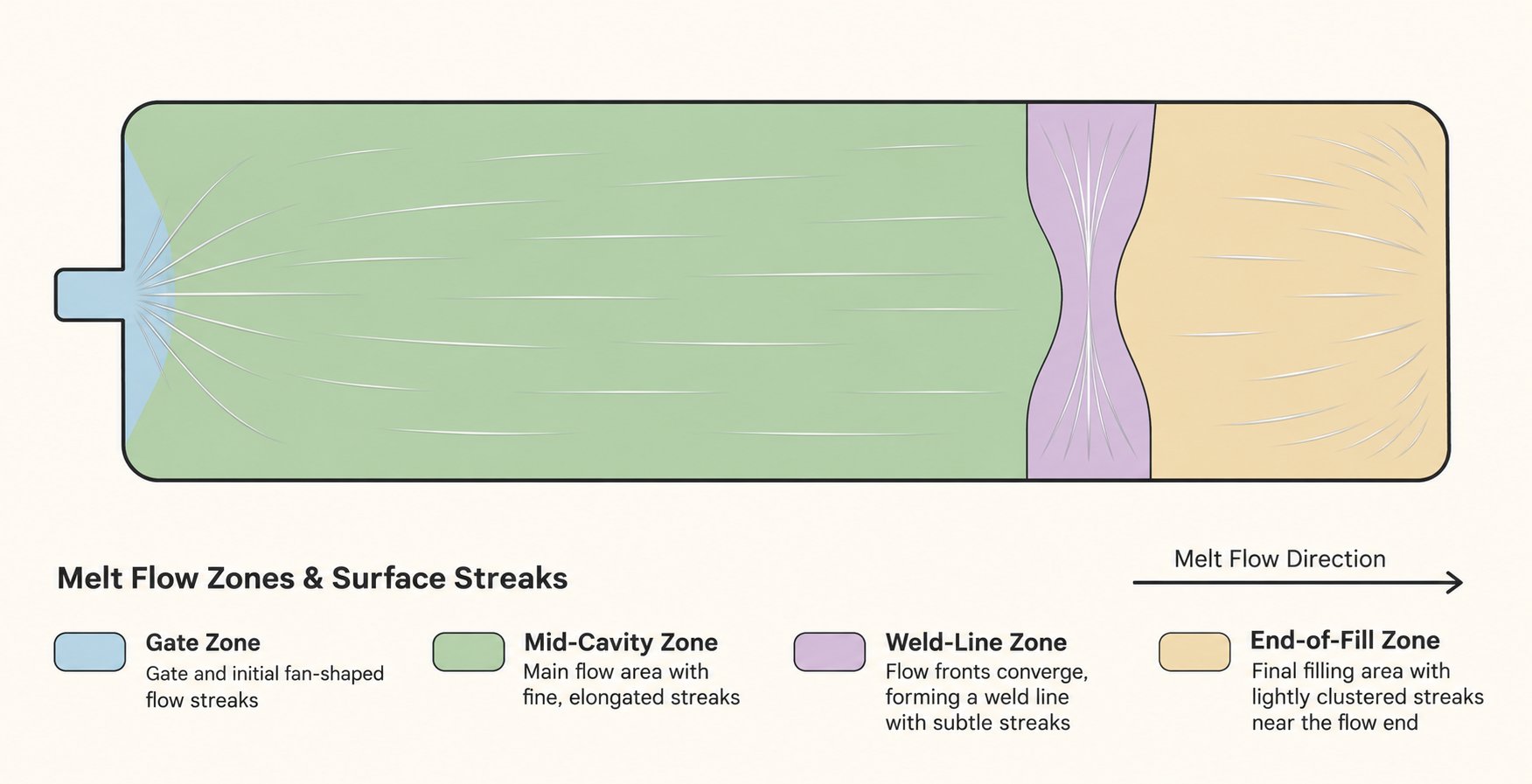
Your decision tree and short-shot tests have narrowed the suspects. But here's a diagnostic shortcut that experienced process engineers rely on instinctively yet rarely see documented: the physical location of splay on the finished part is itself a root-cause indicator. Silver streaks clustered near the gate point to a completely different set of problems than streaks appearing at the last area to fill. Learning to read these location-based clues can cut your troubleshooting time in half — sometimes more — because the part is essentially showing you where the gas entered the flow front and when.
Gate-Area Splay and What It Reveals
When splay concentrates at or immediately around the gate, you're looking at gas that entered the melt stream early — before the material had traveled any significant distance into the cavity. Three culprits dominate this pattern:
- Moisture in the resin. Wet pellets generate steam the moment they encounter barrel heat, and that steam rides into the cavity with the very first material through the gate. You'll typically see dense, evenly spaced streaks fanning outward from the gate in the flow direction. If the streaks are U-shaped and have a dull, hazy appearance, moisture is the most likely cause.
- Excessive screw decompression. Too much suck-back after screw recovery pulls a pocket of air into the nozzle tip. On the next shot, that air slug is the first thing injected into the cavity — producing a concentrated burst of silver right at the gate on the initial fraction of the fill. This pattern often varies slightly from cycle to cycle because the volume of entrained air depends on how consistently the check ring seats. Garrett MacKenzie of Plastic411 emphasizes that decompression should use the minimum speed and position, since setting suck-back too fast or too far is a frequent and overlooked source of gate-area splay.
- Shear degradation at a restrictive gate. A gate with an undersized cross-section forces the melt through a narrow orifice at high velocity. The resulting shear generates intense localized heat — sometimes enough to thermally crack the polymer and release volatiles right at the gate entrance. You'll notice the streaks radiate outward in a starburst pattern centered on the gate, and they may intensify when injection speed increases. Enlarging the gate or switching to a less restrictive gate geometry often resolves this type permanently.
A practical tip: if you see splay exclusively at the gate and nowhere else on the part, try reducing injection speed during just the first 10-15% of the fill. Profiling the injection speed — starting slow through the gate, then accelerating once the melt enters the wider cavity — can eliminate shear-related gate splay without affecting cycle time significantly.
Mid-Flow and End-of-Fill Splay Patterns
Splay appearing well downstream from the gate tells a different story. The melt traveled through the gate cleanly, but something went wrong later in the process — or, more precisely, something went wrong earlier in the barrel and only became visible as the degraded material finally reached the cavity surface during filling.
Thermal degradation is the leading suspect whenever mid-flow splay worsens over consecutive cycles. Here's why: resin that sits too long in a heated barrel undergoes progressive chain scission, releasing volatile byproducts. Each cycle adds another increment of degraded material to the melt pool. The first few shots after startup may look clean because the barrel contains relatively fresh resin, but after 15-20 cycles, the accumulated degradation products begin showing up as streaks in the middle and downstream portions of the part. Common root causes include an oversized barrel relative to the shot size (creating excessive residence time), barrel temperatures set higher than necessary, or dead spots in hot-runner manifolds where material hangs up and cooks before periodically washing into the flow stream.
End-of-fill splay deserves special attention because it can signal trapped gas from poor venting rather than any material or barrel issue. As the melt front approaches the last areas to fill — typically opposite the gate or at the ends of long flow paths — it compresses the air ahead of it. If the mold's vents are clogged, too shallow, or poorly located, that compressed gas has nowhere to escape. It gets folded back into the melt front, producing silver streaks (and sometimes burn marks) at the extremities of the part. Cleaning or deepening the vents is the corrective action here, not adjusting barrel temperatures or drying protocols.
Weld-Line and Flow-Hesitation Splay
Some parts show splay only at weld lines or in areas where the flow hesitates around cores, ribs, and bosses. This selective pattern puzzles many operators because the rest of the part looks perfectly clean.
The explanation connects back to fountain flow. When two melt fronts converge at a weld line, gas that was safely trapped in the interior of each flow stream suddenly gets exposed at the meeting point. The converging fronts push the gas to the surface, where it stretches into visible streaks along the weld. Similarly, when flow hesitates around a geometric feature — slowing down, splitting, and rejoining — small pockets of air or volatile gas re-emerge at the surface in the hesitation zone.
Fixing weld-line and hesitation splay often requires a combination of approaches: improving venting at the weld-line location, raising mold temperature locally to keep the melt fronts fluid longer, or adjusting gate location so the weld line shifts to a less critical area. Process-only adjustments rarely provide a complete solution for this pattern; mold-side changes are usually necessary.
Location-Based Diagnostic Quick-Reference
The table below maps splay location to its most probable causes and gives you a single first action to take. Think of it as a triage guide — the fastest way to figure out how to fix splay in injection molding before diving into deeper analysis.
| Splay Location | Most Likely Causes | First Diagnostic Action |
|---|---|---|
| At or near the gate (starburst pattern) | Moisture in resin; excessive decompression pulling air into the nozzle; shear degradation from restrictive gate or high initial injection speed | Dry a small resin sample in a lab oven and remold. If splay persists, reduce suck-back distance to minimum, then profile injection speed slower through the gate. |
| Mid-cavity, worsening over consecutive cycles | Thermal degradation from excessive barrel temperature, long residence time, or hot-runner dead spots | Purge barrel with fresh material and remold immediately. If first shots are clean but splay returns after 15-20 cycles, investigate residence time and barrel sizing. |
| End of fill (last areas to pack out) | Trapped air from inadequate venting; gas compressed ahead of the melt front | Inspect and clean mold vents. Deepen vent channels if they are below the recommended depth for the resin being processed. |
| At weld lines or flow-hesitation zones | Gas re-emerging at converging melt fronts; air pockets trapped around cores, ribs, or bosses | Add or improve venting at the weld-line location. Increase mold temperature locally. Consider repositioning the gate to shift the weld line. |
| Random, intermittent positions (varies shot to shot) | Contamination (mixed resin, degraded regrind, purge residue); inconsistent check-ring seal | Purge barrel completely, reload 100% virgin material, and run 20+ consecutive shots to see if pattern stabilizes or disappears. |
Bookmark this table and keep it near the press. When silver streaks appear, your first glance at the part — specifically where on the part — gives you a running head start on how to get rid of splay in injection molding before you even open the machine controller. And once you've confirmed the location pattern, the next critical variable to consider is the resin itself — because different polymer families generate gas through very different chemical pathways, and each one demands its own prevention strategy.
Material-Specific Splay Behavior and Drying Parameters
A polycarbonate lens housing and a polypropylene storage bin can run on the same injection molding machine, through the same nozzle, at similar cycle times — and one will be plagued by injection molding defects like splay while the other never shows a single silver streak. The difference isn't luck. It's chemistry. The resin family you're processing determines how aggressively your material absorbs moisture, what gases it releases under heat, and how narrow your safe processing window really is. Ignore these material-specific behaviors, and even a perfectly tuned process will produce splay the moment ambient humidity rises or barrel temperature drifts.
Why Resin Family Determines Splay Risk
The single most important material property for splay risk is hygroscopicity — whether the polymer absorbs moisture into its molecular structure or simply carries water on the pellet surface.
Hygroscopic resins — including polycarbonate (PC), nylon (PA6, PA66), PET, PMMA, ABS, PBT, and TPU — pull water molecules from the surrounding air and trap them within the pellet. A pellet can look completely dry on the outside while harboring enough internal moisture to ruin every part it produces. As Jinxin Extruder's technical guide explains, these materials hold water inside their pellet structure, meaning a standard hot-air dryer may remove surface water but leave internal moisture behind. That hidden moisture flashes to steam the instant it hits a barrel above 100 °C, and the result is pervasive splay across every shot.
Non-hygroscopic resins — polyethylene (PE), polypropylene (PP), polystyrene (PS), and acetal (POM) — don't absorb water internally. Moisture sits on the pellet surface, usually from condensation, humid storage, or wet packaging. For these materials, proper storage and a basic hot-air hopper dryer are generally sufficient to prevent moisture-related splay. That said, surface moisture on non-hygroscopic pellets can still cause problems — especially if pellets were exposed to a humid workshop or rapid temperature swings that create condensation. The defect is the same silver streak, but the fix is simpler.
There's another moisture-related phenomenon worth mentioning here: mold sweating. When a cold mold surface sits below the dew point of the surrounding air, condensation forms directly on the cavity wall. This condensation creates a hazy, cloud-like discoloration sometimes mistaken for splay. Injection mold sweating causing splay-like marks is technically a different defect (moisture blush), but it shows up on the same troubleshooting radar. The fix is raising mold temperature or reducing shop-floor humidity — not adjusting drying parameters. Recognizing the difference saves you from chasing a resin-drying problem that doesn't exist.
How Different Resins Degrade and What They Release
Splay doesn't always come from moisture alone. Heat splay in injection molding — driven by thermal degradation rather than water vapor — produces different volatile byproducts depending on the resin family. Understanding these differences helps you interpret what's happening inside the barrel even when you can't see it directly.
- Polycarbonate (PC) is particularly sensitive to both moisture and heat. In the presence of water, PC undergoes hydrolysis, breaking ester linkages in the polymer chain and releasing CO₂ and bisphenol-A vapors. Even without moisture, excessively high melt temperatures or long residence times cause thermal chain scission that releases similar volatiles. The practical consequence? PC splay can come from either insufficient drying or overheating — and the visual appearance on the part looks nearly identical in both cases. The diagnostic decision tree from earlier becomes essential here.
- Nylon (PA6, PA66) absorbs moisture aggressively — up to 2.5% by weight in some grades under ambient conditions. Water molecules actually bond within the amide linkages of the polymer chain. During processing, that trapped water vaporizes and drives hydrolytic chain scission simultaneously. The result is both visible splay and a permanent loss of molecular weight, meaning the part may also be mechanically weaker than spec. Nylon is one of the few resins where drying isn't just about cosmetics — it's about structural integrity.
- PET (polyethylene terephthalate) undergoes hydrolytic chain scission when processed with excess moisture, producing acetaldehyde as a primary volatile byproduct. Published research on PET degradation confirms that acetaldehyde, formaldehyde, and benzaldehyde compounds are among the volatiles released during thermal breakdown of PET. In food-contact and beverage-packaging applications, even trace acetaldehyde can affect taste and regulatory compliance — making PET splay not just a visual defect but a product-safety concern.
- ABS (acrylonitrile butadiene styrene) is mildly hygroscopic and tends to show splay at moisture levels above roughly 0.05-0.1%. Thermal degradation in ABS targets the butadiene rubber phase first, releasing volatile organics and causing a yellowish discoloration alongside silver streaks. If your ABS parts show splay plus yellowing, suspect heat more than moisture.
- PMMA (acrylic) absorbs moisture and degrades thermally by depolymerizing back to methyl methacrylate monomer. The volatile release can produce both splay and a noticeable chemical odor at the press. Processing PMMA within a tight temperature window and ensuring thorough drying are both critical.
- POM (acetal) is technically non-hygroscopic, but it's extremely sensitive to thermal degradation. Overheating POM releases formaldehyde gas — which not only causes splay but also presents a health hazard. If you see splay on POM parts and smell a sharp, pungent odor, the barrel is too hot or the residence time is too long. Drying won't help here; temperature control is everything.
The takeaway is straightforward: two parts showing identical-looking silver streaks can have completely unrelated root causes depending on the resin being processed. A drying fix that eliminates splay in nylon won't help a POM part degrading from excess barrel heat. Material knowledge isn't optional — it's the foundation of accurate diagnosis.
Resin-Specific Drying Parameters Reference
The table below provides generally accepted drying parameters for common injection molding resins. These values represent industry-standard ranges — always confirm against the specific resin manufacturer's datasheet for your grade, because filler content, molecular weight, and additives can shift the optimal targets.
| Resin Family | Hygroscopic | Drying Temp Range | Drying Time Range | Max Moisture Target | Special Notes |
|---|---|---|---|---|---|
| PC (Polycarbonate) | Yes | 120-130 °C (248-266 °F) | 3-4 hours | 0.02% | Extremely sensitive to hydrolysis. Even slight over-drying at excessive temperatures can yellow the resin. |
| PA6 / PA66 (Nylon) | Yes | 80-85 °C (176-185 °F) | 4-6 hours | 0.10-0.20% | Absorbs moisture rapidly after drying. Minimize exposure time between dryer and barrel. Some grades tolerate up to 0.20% for non-critical parts. |
| ABS | Yes | 80-85 °C (176-185 °F) | 2-4 hours | 0.05-0.10% | Drying above 85 °C risks softening and pellet clumping. Butadiene phase degrades first under excessive heat. |
| PET (Polyethylene Terephthalate) | Yes | 150-175 °C (302-347 °F) | 4-6 hours | 0.02% | Requires aggressive drying. Releases acetaldehyde if processed wet — critical for food-contact applications. |
| PMMA (Acrylic) | Yes | 75-80 °C (167-176 °F) | 3-4 hours | 0.04-0.06% | Overheating during drying can cause pellet degradation and optical haze in transparent parts. |
| PBT (Polybutylene Terephthalate) | Yes | 120-140 °C (248-284 °F) | 3-4 hours | 0.02-0.04% | Similar drying behavior to PET. Hydrolysis sensitivity increases with glass-fiber reinforcement. |
| TPU (Thermoplastic Polyurethane) | Yes | 80-110 °C (176-230 °F) | 2-4 hours | 0.02-0.05% | Wide range of hardness grades; softer grades may require lower drying temperatures to prevent pellet sticking. |
| POM (Acetal) | No | 80-100 °C (176-212 °F)* | 2-3 hours* | 0.10% | *Drying usually optional, done mainly to preheat and remove surface moisture. Splay in POM is almost always thermal degradation, not moisture. |
| PP (Polypropylene) | No | 80-100 °C (176-212 °F)* | 1-2 hours* | N/A (surface only) | *Typically only needs surface-moisture removal. Hot-air hopper dryer is sufficient. Splay in PP usually indicates contamination or degradation. |
| PE (Polyethylene) | No | 80-90 °C (176-194 °F)* | 1-2 hours* | N/A (surface only) | *Same as PP — surface drying only. If splay appears, look at shear, degradation, or contamination rather than moisture. |
A critical note on dryer type: for every hygroscopic resin in the table above, a desiccant dryer delivering air at a dew point of -40 °C (-40 °F) or lower is the production standard. Hot-air ovens and basic hopper dryers push heated ambient air through the material, which removes surface water effectively but cannot pull moisture from inside the pellet. You might measure a temperature of 120 °C in the hopper and assume the resin is dry — but if the drying air still carries ambient humidity, the moisture gradient needed to extract internal water simply doesn't exist. The pellets end up warm, not dry. For lab-scale validation or small-batch prototyping, an oven can work if the resin is spread thin and given extra time. For production runs, desiccant drying is non-negotiable.
One more detail that catches shops off guard: drying doesn't end when the resin leaves the hopper. Hygroscopic materials like PC, nylon, and PET can reabsorb significant moisture within minutes if exposed to workshop air during transfer. A long, open conveying path between the dryer and the machine feed throat can undo hours of careful drying. Sealed hoppers, dry-air conveying lines, and minimizing the distance between dryer and press all protect your investment in properly dried material.
With material behavior and drying parameters now mapped out by resin family, the next challenge becomes visual — specifically, how to tell splay apart from the half-dozen other surface defects that mimic its appearance but demand entirely different corrective actions.
Splay Versus Look-Alike Defects: How to Tell Them Apart
Misdiagnosis is one of the most expensive mistakes in injection molding troubleshooting. You spot silver-ish marks on a part, assume it's splay, and spend two hours adjusting drying protocols and barrel temperatures — only to discover the real problem was condensation on a cold mold face or a contaminated batch of regrind causing delamination. The corrective actions for these defects are completely different, so getting the injection molding splay definition straight — and knowing exactly what splay is not — saves real time and real money on the production floor.
Several common surface defects share enough visual similarity with splay to fool even experienced operators under quick inspection. Let's break down each one so you can tell them apart at a glance.
Splay Versus Flow Lines and Fold Lines
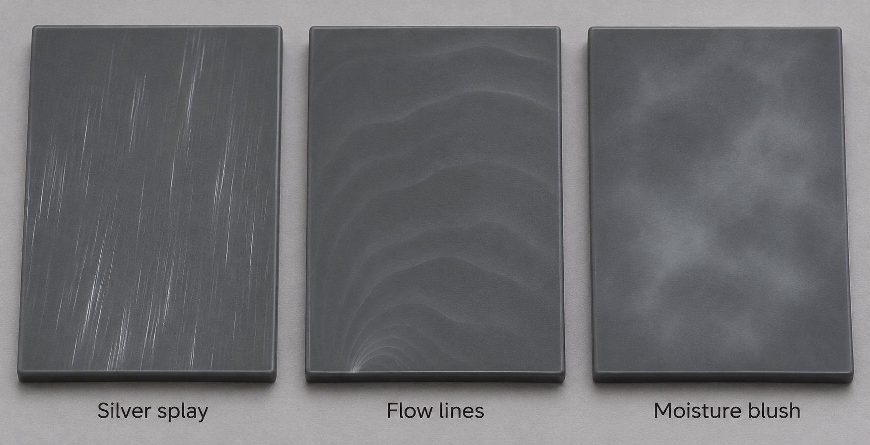
Flow lines (also called flow marks) are wavy, off-color bands or ripples that follow the contour of the advancing melt front. Imagine the concentric rings you see when you drop a stone into still water — flow lines echo that pattern, curving along the part surface in gentle arcs. They're caused by uneven cooling, hesitation in the flow front, or an injection speed that's too low for the geometry. As Jeek Mould's defect overview explains, flow lines typically appear when the material cools faster than it should or when the melt hesitates around thickness changes.
Here's the critical distinction: flow lines lack the metallic-silver, streaky appearance that defines splay. They're more of a matte, slightly discolored wave pattern — think of subtle color shifts rather than shiny silver flames. Flow lines also tend to be broader and less sharply defined. If the mark on your part looks like a gentle ripple rather than a directional silver streak, you're probably dealing with a flow line, and the fix involves raising melt or mold temperature and adjusting injection speed — not checking your dryer.
Fold lines are different still. These are sharp creases or visible seams where the melt surface literally folded over itself during filling. You'll notice them as thin, well-defined lines — almost like someone pressed a crease into the surface with a fingernail. They form when the melt front rolls forward unevenly, typically at abrupt wall-thickness transitions or around features that split and redirect flow. Fold lines are geometric and crisp; splay is diffuse and silvery. The two look nothing alike under close inspection, but from across the shop floor, a fold line running along the flow direction can be mistaken for a single splay streak.
A reliable way to distinguish all three: hold the part at an angle under a bright light and slowly rotate it. Splay will flash with a distinctive silvery, almost iridescent shimmer because the disrupted surface layer scatters light differently than the surrounding polymer. Flow lines shift as dull, matte bands. Fold lines appear as sharp shadow lines that don't change character as you tilt the part.
Distinguishing Splay From Delamination, Scratches, and Moisture Blush
Delamination looks alarming — thin, flaky layers of material peeling or lifting away from the part surface, almost like sunburned skin. It's caused by contamination (incompatible resin blends, foreign material in the hopper) or excessive shear that forces the surface layer to separate from the bulk. Here's the quickest field test: run your fingernail across the suspect area. If you can catch an edge and lift a thin layer, it's delamination, not splay. An injection molding splay defect disrupts the surface optically — the silver streaks are embedded in the skin layer — but it doesn't create a physically separable flake. The corrective paths diverge completely: delamination demands a contamination investigation and possibly a full barrel purge with material verification, while splay points you toward moisture, degradation, or shear.
Scratches are the simplest to rule out, yet they still occasionally get logged as splay on quality reports. The giveaway? Direction. Splay always aligns with the melt-flow path — streaks radiate outward from the gate along the same vectors the plastic traveled during filling. Scratches, by contrast, follow random directions that have nothing to do with flow. They might run perpendicular to the flow path, cross each other at odd angles, or concentrate in areas where parts contact each other during handling or packing. A scratch also typically has a clean, V-shaped groove visible under magnification, while a splay streak is a flat, shallow surface disruption with no measurable depth.
Moisture blush — sometimes called mold sweating — is the trickiest impostor. It produces a hazy, cloud-like discoloration across the part surface that can look vaguely like widespread splay at first glance. But the injection molding splay cause is gas erupting from within the melt, while moisture blush originates outside the melt entirely. When the mold surface temperature drops below the dew point of the surrounding shop air, condensation forms directly on the cavity wall. The incoming melt contacts that thin water film, and the result is a diffuse, foggy appearance — not sharp directional streaks. Moisture blush is uniform and cloud-like rather than streaky; it doesn't follow flow vectors; and it often appears on just one mold half (typically the cooler core side). Raising mold temperature above the shop-floor dew point or reducing ambient humidity eliminates it immediately — no drying-parameter changes required.
Differential-Diagnosis Quick-Reference Table
When you're standing at the press with a rejected part in hand, you need a fast visual checklist. The table below puts the key distinguishing features side by side so you can confirm — or rule out — splay in under a minute.
| Defect Name | Visual Appearance | Directional Pattern | Primary Cause | Quick Test to Confirm |
|---|---|---|---|---|
| Splay (Silver Streaks) | Metallic-silver or whitish flame-shaped streaks on the surface | Always aligns with melt-flow direction, radiating from the gate | Gas in the melt (moisture, thermal degradation, shear, or entrained air) | Dry resin thoroughly and remold. If streaks vanish, moisture confirmed. If not, follow the diagnostic decision tree for degradation, shear, or air. |
| Flow Lines (Flow Marks) | Wavy, off-color bands or ripples; matte finish, no silver sheen | Follows the contour of the advancing melt front in curved, wave-like arcs | Uneven cooling, low injection speed, or flow hesitation at thickness changes | Increase injection speed or raise melt/mold temperature. Marks should diminish as the flow front becomes more uniform. |
| Fold Lines | Sharp, crease-like lines; thin and well-defined | Follows geometry transitions; can align with flow but appears as a single crisp line, not diffuse streaks | Melt surface folding over at abrupt wall-thickness changes or flow-direction shifts | Smooth the wall-thickness transition in the problem area or adjust gate location to change how the melt front approaches the feature. |
| Delamination | Peeling, flaking surface layers; may look silvery but has physical depth | No consistent directional pattern; follows stress zones or contamination distribution | Contamination, incompatible resin blend, or extreme shear at the surface | Run a fingernail across the mark. If you can catch and lift a thin layer, it's delamination. Investigate material contamination and purge the barrel. |
| Scratches | Thin, linear marks; may appear shiny or dull depending on depth | Random directions unrelated to melt flow; may cross each other | Mechanical damage during ejection, handling, or packing | Check if marks appear on parts straight from the mold (ejection damage) or only after handling. Inspect ejector pins, slides, and packing procedures. |
| Moisture Blush (Mold Sweating) | Hazy, cloud-like discoloration; diffuse and uniform rather than streaky | No directional pattern; often covers broad areas or appears on one mold half | Condensation on a cold mold surface that is below the shop-floor dew point | Raise mold temperature 5-10 °C above the dew point. If haze disappears, condensation was the cause — not gas in the resin. |
Print this table and keep it at your quality-inspection station. The few seconds it takes to cross-reference a suspect mark against these six defect profiles can prevent hours of misdirected troubleshooting. Remember, an accurate diagnosis isn't just about identifying what the defect is — it's about confirming what it isn't, so you direct your corrective actions at the actual root cause from the start.
Once you've confirmed the defect is genuinely splay and pinpointed its likely source through location analysis, the question shifts from diagnosis to action: which specific process parameters should you adjust, by how much, and in what order? The answer depends entirely on which type of splay your diagnosis revealed.
Injection Molding Troubleshooting Splay: Process Parameter Quick-Reference by Type
You've confirmed the defect is splay — not flow lines, not fold lines, not moisture blush. You've used the diagnostic decision tree and location analysis to isolate the most probable gas source. The pressing question now is practical: which knobs do you turn, which direction, and how far? The answer changes dramatically depending on whether you're dealing with moisture, thermal degradation, shear, decompression, or contamination. Adjusting the wrong parameter for the diagnosed cause wastes cycles and can introduce entirely new defects.
The guidance below is organized by confirmed splay type so you can jump directly to the corrective actions that match your diagnosis.
Moisture Splay Process Corrections
Moisture is the most common driver of splay, and fixing it rarely involves touching the machine controller at all. The corrective actions live upstream of the press:
- Verify dryer performance before adjusting anything else. Check that your desiccant dryer is delivering air at a dew point of -40 °C or lower. Measure the actual hopper temperature — not the setpoint — at the discharge. A dryer displaying 120 °C on the controller while delivering 95 °C at the hopper outlet isn't drying your resin to spec. Use a portable moisture analyzer to confirm the resin moisture content meets the target for your specific polymer (refer to the drying parameters table in the previous section).
- Inspect hopper-loader seals and lids. A cracked loader gasket or an open hopper lid allows humid shop air to flow directly over material that was dried minutes earlier. Hygroscopic resins like PC and nylon can reabsorb enough moisture in 15-20 minutes of ambient exposure to restart the splay cycle.
- Reduce nozzle drool between shots. Drool that hangs from the nozzle tip can wick moisture from the air and carry it into the next shot. Ensure the suck-back setting creates just enough retraction to break the drool string without pulling air into the melt channel. If drool persists, verify nozzle temperature isn't set excessively high relative to the melt profile.
A useful reality check: if you've confirmed proper drying yet splay persists, resist the temptation to increase drying temperature further. Over-drying certain resins — especially nylon and TPU — can cause pellet degradation, color shift, or agglomeration in the hopper. Instead, move to the next suspect on the decision tree.
Thermal Degradation and Shear Splay Adjustments
When moisture has been ruled out, the root cause shifts to energy-related mechanisms — either too much heat over too long a time (thermal degradation) or too much mechanical energy applied too quickly (shear). These two categories account for the majority of non-moisture splay cases, and distinguishing between them matters because the corrective actions point in different directions.
Thermal degradation splay often hides behind a subtle but critical concept: residence time. Imagine running a small part — say, a 50-gram shot — on a machine with a 500-gram barrel capacity. The barrel holds roughly ten shots' worth of material at any given moment. At a 30-second cycle time, each pellet spends approximately five minutes soaking in a heated barrel before it ever reaches the mold. For heat-sensitive resins like POM or PVC, five minutes at processing temperature is enough to initiate chain scission and volatile release. Rosti's technical guide on residence time notes that small shot sizes using minimal barrel capacity result in long residence times and polymer degradation — a relationship many processors overlook because the barrel temperature itself looks reasonable on the controller screen.
Here's the critical insight: reducing barrel temperature alone may not help if the real problem is a barrel-to-shot-size mismatch that forces excessive residence. A 10 °C temperature drop barely compensates for material sitting in the barrel three times longer than the resin manufacturer intended. The permanent fix in these cases is moving the mold to a smaller-barreled machine where shot size uses 40-70% of barrel capacity.
Shear splay demands a different approach. The gas isn't forming because the resin sat too long in heat — it's forming because the resin was subjected to violent mechanical deformation as it squeezed through a tight restriction at high velocity. Garrett MacKenzie of Plastic411 identifies several shear-related origins: nozzle tips with orifices that are too small, gates that are undersized for the flow rate, and feed-zone temperatures set too low — which paradoxically increases shear by forcing the screw to work harder against semi-solid pellets in the compression zone.
Process adjustments for shear splay include slowing injection speed (especially through the gate), reducing back pressure, and verifying that barrel feed-zone temperatures are adequate to begin softening the resin before it reaches the compression section. But when the shear source is geometric — a pinpoint gate on a large part, a runner diameter that's too narrow, or a nozzle tip with a burred orifice — parameter changes alone won't eliminate the defect. The real fix is mechanical: opening up the gate, increasing runner diameter, replacing damaged nozzle tips, or profiling the injection speed so the melt passes through the restriction at a reduced velocity before accelerating into the open cavity. MacKenzie recommends dividing the shot size by six and setting position profiles in equal segments, then reducing speed one segment at a time to pinpoint exactly where in the flow path the shear is occurring.
Decompression (suck-back) splay has the simplest fix but is among the most frequently overlooked causes. Reduce the decompression distance to the absolute minimum needed to prevent nozzle drool — often just 2-5 mm. Also reduce the decompression speed; as MacKenzie notes, suck-back that is too fast or positioned too far draws air into the melt, producing the characteristic burst of silver at the gate on the next shot.
Contamination splay requires a full barrel purge with an appropriate purging compound, followed by reloading 100% virgin resin. If regrind is part of your blend, inspect its quality: degraded regrind, mixed resin types, or foreign particles all generate volatiles under barrel heat that the base resin would tolerate without issue. After purging, run a minimum of 20 consecutive shots before evaluating — contamination trapped in check-ring crevices or screw-flight dead zones can take multiple cycles to fully flush.
Parameter Adjustment Quick-Reference Table
The table below bridges the gap between diagnosis and corrective action. Find your confirmed splay type in the left column and follow the parameter adjustments across the row. Typical magnitudes are starting points — always verify results and adjust incrementally.
| Splay Type | Melt Temperature | Mold Temperature | Injection Speed | Back Pressure | Screw RPM | Decompression Distance | Cycle Time / Residence |
|---|---|---|---|---|---|---|---|
| Moisture | No change (fix drying first) | No change | No change | No change | No change | Minimize to prevent drool (2-5 mm) | No change (verify dryer dew point, hopper seals, conveying lines) |
| Thermal Degradation | Decrease 10-15 °C across all zones | No change or slight increase to compensate for lower melt temp | No change initially | Decrease 10-15% to reduce shear heating | Decrease 10-20% to reduce frictional heat | No change | Reduce cycle time if possible; move to smaller barrel if shot size is below 30% of barrel capacity |
| Shear | No change or slight increase to lower melt viscosity | Increase 5-10 °C to improve flow | Decrease 20-30%, especially through the gate; use speed profiling | Decrease 10-20% | Decrease 15-25% | No change | No change (also evaluate gate size, runner diameter, and nozzle-tip orifice) |
| Decompression (Air) | No change | No change | No change | No change | No change | Reduce to minimum (2-5 mm); also reduce suck-back speed | No change (inspect check ring for wear if air ingestion persists) |
| Contamination | No change | No change | No change | No change | No change | No change | Full barrel purge; reload 100% virgin resin; inspect regrind quality and hopper cleanliness |
Notice a pattern in the table? For four out of five splay types, the fix is not a barrel temperature change. That's worth underscoring because lowering melt temperature is the reflexive first move most operators make when silver streaks appear. If the actual root cause is moisture, decompression air, or contamination, dropping barrel temps accomplishes nothing — and may introduce new problems like short shots, increased viscosity, or poor surface finish.
The fastest path to eliminating splay is matching the corrective action to the confirmed root cause — not defaulting to the same temperature reduction every time silver streaks appear.
Parameter adjustments solve most splay problems. But some cases resist every process tweak you throw at them — because the real source of the gas isn't the process settings at all. It's the hardware behind the settings: worn screws, degraded barrel bores, and hot-runner dead zones that no amount of controller adjustment can compensate for.
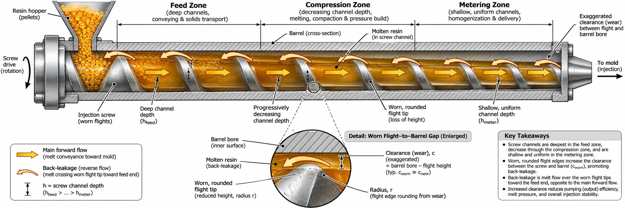
Screw, Barrel, and Hot Runner Contributions to Plastic Injection Molding Splay
You've verified the resin is bone dry. You've profiled injection speed, reduced barrel temperatures, and minimized decompression. The process parameters are textbook-perfect — yet silver streaks keep showing up, cycle after cycle. If this scenario sounds familiar, the problem likely isn't what you're telling the machine to do. It's what the machine is physically capable of doing with the plasticizing hardware installed inside it.
Worn screws, degraded barrel bores, failing check rings, and stagnant hot-runner zones are among the most overlooked sources of plastic injection molding splay because they degrade gradually. Nobody walks in one morning to find a screw that suddenly lost 0.5 mm of flight depth overnight. The wear accumulates over thousands of hours, and the splay it produces creeps in so slowly that operators often attribute it to material lot variation or seasonal humidity changes rather than the hardware sitting inside the barrel.
How Worn or Mismatched Screws and Barrels Cause Splay
A screw and barrel are precision-fit components. The clearance between the outer diameter of the screw flights and the inner bore of the barrel is typically just 0.05-0.15 mm per side on a new assembly, depending on machine size. That tight clearance serves a critical purpose: it forces resin forward through the compression and metering zones under controlled pressure, ensuring uniform melting, proper gas expulsion, and consistent shot delivery.
When that clearance opens up due to wear, two things happen that directly produce plastic injection mold splay:
- Back-leakage increases residence time. Resin that should be moving forward through the metering zone instead flows backward over the worn flight lands into the compression and feed zones. This back-leakage — sometimes called "slippage" — means the same material recirculates through the heated barrel multiple times before finally exiting the nozzle. Each extra pass through the barrel adds thermal history. For heat-sensitive resins, that additional residence time pushes the polymer past its degradation threshold, generating volatile byproducts that appear as splay on the finished part. Santa Fe Machine Works identifies prolonged residence time in a worn barrel as a direct contributor to material degradation, burn marks, and gas-related defects — all symptoms that share a common root in excessive flight-to-bore clearance.
- Compression loss disrupts melting uniformity. The compression zone of a screw is designed to squeeze air out of the resin bed and generate the shear energy needed to fully melt the polymer. When flight depth increases due to wear, compression drops. The resin reaches the metering zone with unmelted pockets, inconsistent temperature distribution, and trapped air that was never properly vented. As MD Plastics' engineering analysis explains, when wear changes screw geometry, the melting location shifts downstream and the process becomes unstable — even when barrel temperatures remain unchanged on the controller screen.
Worn check rings (non-return valves) add a second failure mode. A check ring that doesn't seat consistently allows melt to leak backward during injection and — more critically for splay — allows air to be drawn into the melt during decompression. You'll recognize this as the same entrained-air mechanism discussed earlier, but here the root cause isn't an aggressive suck-back setting. It's a mechanical component that physically cannot seal, regardless of what the controller is set to. Reducing decompression distance to zero won't help if the check ring itself is worn, scored, or warped. Inspecting the check ring for uneven wear patterns, seat damage, or excessive clearance between the ring and the barrel bore is an essential diagnostic step when decompression splay resists all process adjustments.
Screw geometry mismatches are a subtler but equally damaging hardware issue. Imagine running a heat-sensitive acetal (POM) or rigid PVC on a general-purpose (GP) screw designed for polyolefins. A GP screw typically has a compression ratio of 2.5:1 to 3.0:1 and relatively shallow metering-zone channels — perfectly adequate for PE and PP, which tolerate aggressive shear without degrading. But POM and PVC have much narrower processing windows. The higher compression ratio generates excessive shear in the transition zone, locally overheating the resin and producing degradation volatiles that emerge as splay. The screw L/D ratio matters too: a shorter L/D (say, 18:1) gives the resin less time and distance to melt uniformly, which forces the compression zone to work harder and generates more shear heat. A longer L/D (22:1 to 24:1) spreads the melting work over more barrel length, reducing the peak shear intensity at any single point.
Channel depth in the metering zone also plays a role. Shallow channels increase shear rate for a given screw speed, while deeper channels reduce it. When the metering channel is too shallow for a shear-sensitive resin, the combination of high shear and insufficient volume creates localized hot spots that degrade the polymer — even though the average melt temperature reading at the nozzle looks acceptable.
When inspection confirms excessive wear or a geometry mismatch, replacing the screw and barrel with components engineered for the specific resin and shot size is the permanent fix — no amount of parameter adjustment can restore geometry that has physically worn away. Suppliers like NANHAIYA offer custom injection molding screw barrels designed around the specific machine, resin, and shot-size requirements, including a technical review of screw geometry, compression ratio, and material-retention concerns, to restore proper plasticizing performance and eliminate hardware-driven splay. The key is matching the replacement components to both the application and the machine — a one-for-one swap of another GP screw into a process that demands resin-specific geometry simply resets the clock on the same problem.
Hot-Runner Dead Spots and Material Hang-Up
If worn screws and barrels produce splay that worsens steadily over time, hot-runner dead spots produce splay that appears and disappears almost randomly — making them one of the most frustrating plastic injection molding defects to diagnose.
Here's what happens inside a hot-runner system. The manifold distributes molten resin from a central inlet to multiple nozzle drops through a network of heated flow channels. In a perfect manifold, every molecule of resin moves through the system at the same rate, reaching each gate at the same temperature and with the same thermal history. In reality, manifold geometry always creates zones where flow velocity drops — corners, channel transitions, areas behind valve pins, and the dead ends of manifold branches. Asaclean's technical analysis confirms that hot runner manifolds and drops have intricate flow channels, corners, and transitions that inevitably create low-flow zones and dead spots where material lingers instead of flowing through.
Material trapped in these dead spots doesn't just sit idle — it continues absorbing heat from the surrounding manifold body. Over hours or days, that stagnant resin undergoes progressive thermal degradation: molecular chains break, volatiles accumulate, and the material darkens. Periodically, a slight pressure fluctuation or a change in flow pattern during injection dislodges a slug of this degraded material and pushes it into the active flow stream. The result? A sudden burst of silver streaks — sometimes accompanied by dark specks — on one or two parts, followed by a run of clean parts, followed by another random outbreak. The intermittent nature is the signature: consistent splay points to process or drying issues, but splay that comes and goes unpredictably across cycles often traces back to hot-runner hang-up.
Diagnosing hot-runner-driven splay requires a different approach than the decision tree used for barrel-related causes:
- Check individual drop temperatures. A thermocouple that has drifted or a heater band that is partially failed can create a cold zone in one drop while the others run normally. The cold zone slows flow, extends local residence time, and promotes degradation in that specific channel. Verifying actual metal temperature at each drop — not just the controller setpoint — often reveals the problem.
- Look for cavity-specific patterns. In a multi-cavity mold, hot-runner splay often appears in the same cavity or the same two cavities rather than uniformly across all cavities. If cavities 3 and 7 consistently show intermittent splay while the others run clean, the manifold branches feeding those cavities likely contain the dead spot.
- Monitor splay frequency over extended runs. If splay events cluster at regular intervals — say, every 30-45 minutes — the timing may correspond to how long it takes degraded material to accumulate and release from a specific dead zone. This periodicity is a strong diagnostic clue.
The corrective actions for hot-runner-related plastic mold injection splay focus on both maintenance and thermal management:
- Periodic manifold purging. Running a purging compound through the hot-runner system at scheduled intervals — not just during color changes — helps flush degraded material from low-flow zones before it accumulates enough to cause visible defects. This is especially important for resins with narrow thermal stability windows, like POM, PVC, and certain grades of PC.
- Thermal profiling of each zone. Map the actual metal temperature of every manifold zone and drop against its setpoint. Zones running more than 5-10 °C above or below target should be investigated for heater or thermocouple issues. Overheated zones accelerate local degradation; underheated zones slow flow and increase residence time.
- Manifold design review during new mold qualification. When specifying a new hot-runner system, ask the manifold supplier about flow-simulation results and the location of any predicted low-velocity zones. Manifold designs that minimize sharp corners, use naturally balanced runner lengths, and avoid unnecessary dead-end branches reduce hang-up risk from the start.
Intermittent splay that defies every process adjustment is the calling card of hardware-driven root causes — worn plasticizing components or hot-runner dead spots that no controller setting can compensate for.
Recognizing when the defect source has moved beyond the reach of process parameters — and into the physical condition of the equipment — is what separates reactive troubleshooting from real problem-solving. It also raises a bigger question: instead of waiting for hardware wear and manifold degradation to announce themselves through splay on finished parts, is there a way to design these problems out of the process before production even begins?
Preventing Splay Defect in Injection Molding During Process Development and Mold Qualification
Every section of this article so far has dealt with the same scenario: splay already exists on a molded part, and you need to figure out why. That's reactive troubleshooting — valuable, necessary, but inherently expensive. Each diagnostic cycle burns resin, ties up machine time, and delays production. What if you could eliminate most splay risk before the first production shot ever fires?
That's exactly what proactive prevention looks like. By evaluating splay-specific risks during mold design, material selection, machine assignment, and process qualification, you build defenses into the system at every stage — rather than scrambling to patch holes after defective parts start piling up in the reject bin.
Designing Splay Out During Mold and Process Qualification
Think about the typical mold qualification sequence. You cut steel, sample the tool, measure dimensions, check cosmetics, and approve the mold for production. Somewhere in that process, someone might notice silver streaks and start adjusting parameters on the fly. But by that point, the gate is already cut, the runners are already sized, and the venting is already machined. You're left optimizing around fixed hardware — the very hardware that may be driving the defect.
A better approach is to evaluate splay risk explicitly during mold steel approval and first-article inspection, treating it as a qualification criterion rather than a nuisance to be tuned away.
Gate sizing deserves the first look. As earlier sections demonstrated, restrictive gates are a primary trigger for shear splay in injection molding. During mold design review, verify that the gate cross-section is adequate for the resin viscosity and the required fill rate. For shear-sensitive resins like POM and rigid PVC, oversizing the gate slightly is a safer bet than undersizing — cosmetic witness marks at the gate are far easier to manage than chronic splay across the entire part.
Runner balancing matters because unbalanced flow creates velocity differences between cavities. The cavity receiving the fastest flow experiences the highest shear, while the slowest-filling cavity risks hesitation marks and end-of-fill gas traps. Both extremes increase splay risk. Mold flow simulation during the design phase can identify these imbalances before steel is ever cut.
Venting adequacy is the third mold-side factor. Rex Plastics notes that venting should be considered long before tooling is manufactured, because vent placement is closely tied to part geometry, flow patterns, and mold construction. Addressing it early prevents the costly modifications that come when trapped air produces end-of-fill splay or burn marks during initial sampling. During first-article runs, produce deliberate short shots at 70%, 85%, and 95% fill to map where the melt front ends up — those last-to-fill zones are exactly where vents need to be placed or deepened.
Moisture verification should be a documented protocol step, not an assumption. Before every qualification run, check resin moisture content with a portable moisture analyzer and record the result. This takes less than five minutes and creates a baseline that eliminates moisture as a variable if splay appears during sampling. Without this data, you'll waste the first hour of every qualification session wondering whether the dryer was running properly overnight.
Perhaps the most powerful prevention tool available during qualification is a process window study. Research published in Polymers demonstrated a systematic method for experimentally developing injection molding process windows by varying primary control variables — melt temperature, mold temperature, and packing pressure — and mapping the boundaries where defects appear. The researchers found that operating near the center of the defined window made part quality less influenced by undesired process variations, promoting a stable and predictable manufacturing process. Applying this concept specifically to splay means intentionally pushing parameters toward their limits during qualification — raising melt temperature until splay appears, lowering it until short shots begin, increasing injection speed until shear splay emerges — and then documenting those boundaries. Production can then run safely inside those limits with a defined margin of safety.
Selecting the Right Material and Machine Combination
Splay prevention doesn't start at the press. It starts in the conference room where material and machine decisions are made — often weeks or months before the mold is ever mounted.
Barrel sizing is the single most overlooked machine-selection factor for splay prevention. When a small part runs on an oversized machine, the shot uses a tiny fraction of the barrel's capacity, and residence time skyrockets. Rosti's technical guide confirms that small shot sizes using minimal barrel capacity result in long residence times and polymer degradation. The industry-standard guideline is to select a machine whose shot capacity uses 40-70% of barrel volume. Below 40%, residence time becomes excessive for most engineering resins. Above 70%, screw recovery may struggle to plasticize the next shot within the available cycle time.
Material selection itself can reduce splay risk before a single pellet reaches the dryer. For applications where moisture sensitivity is a concern, consider specifying a less-hygroscopic grade within the same resin family — mineral-filled nylon, for example, absorbs less moisture than unfilled nylon because the mineral filler displaces some of the hygroscopic polymer matrix. Pre-dried masterbatch or pre-compounded color concentrates also reduce the total moisture load entering the barrel compared to blending virgin resin with undried color at the press.
Screw geometry specification closes the loop. Rather than accepting whatever general-purpose screw ships with a new machine, specify screw compression ratio, channel depth, and L/D ratio based on the resin family that will run most frequently. A screw optimized for the application melts the polymer uniformly, generates controlled shear, and minimizes dead zones where material can hang up and degrade — all of which directly reduce splay risk at the hardware level.
Proactive Prevention Checklist
Use the following checkpoints as a standard review during new-mold qualification or when onboarding a new resin. Each item targets a specific splay mechanism and takes minutes to verify — but can save days of reactive troubleshooting downstream.
Mold Design
- Gate cross-section is sized for the resin viscosity and fill rate; no restrictive pinpoint gates on shear-sensitive resins
- Runners are balanced so all cavities fill at similar velocities and pressures
- Vent locations are confirmed via short-shot mapping at 70%, 85%, and 95% fill during first-article sampling
- Vent depth meets the resin manufacturer's recommendation (typically 0.01-0.05 mm depending on resin family)
- No sharp corners or dead-end branches in hot-runner manifold geometry that could trap and degrade material
Material Selection
- Resin grade's moisture sensitivity is documented; drying protocol is established before sampling begins
- Less-hygroscopic grades or mineral-filled alternatives have been evaluated where splay risk is high
- Regrind percentage and quality standards are defined; maximum allowable regrind ratio is documented
- Pre-dried masterbatch or pre-compounded color is specified when possible to reduce moisture introduction
Machine Selection
- Shot size uses 40-70% of barrel capacity to keep residence time within the resin's thermal stability window
- Screw geometry (compression ratio, L/D, channel depth) matches the primary resin family
- Check ring and nozzle tip are inspected and in good condition before qualification begins
- Desiccant dryer delivers air at -40 °C dew point or lower for all hygroscopic resins
Process Documentation
- Moisture content is measured and recorded with a portable analyzer before every qualification run
- Process window study is completed during qualification, with splay-onset boundaries documented for melt temperature, injection speed, and back pressure
- Production parameter setpoints are established at or near the center of the qualified window, with defined alarm limits
- Standard work instructions include dryer verification, hopper-seal checks, and suck-back settings as pre-startup items
The cheapest splay defect to fix is the one you designed out of the process before production started.
Splay as a defect in injection molding will never be completely eliminated from every shop floor — resin chemistry, ambient conditions, and equipment wear guarantee that silver streaks will appear sooner or later. But the difference between a shop that spends hours chasing symptoms and one that resolves splay in minutes comes down to preparation. When the mold is designed with adequate gating and venting, the material is matched to the machine's barrel capacity, the screw geometry fits the resin, and the process window is documented with clear boundaries, splay becomes a five-minute diagnostic exercise instead of a two-day production crisis. That shift — from reactive firefighting to proactive engineering — is the real fix this article set out to deliver.
Frequently Asked Questions About Injection Molding Splay
1. What is splay in injection molding and why does it happen?
Splay refers to silver or whitish streaks that fan outward from the gate across an injection-molded part's surface. It occurs when trapped gas — from moisture vaporization, thermal degradation of the polymer, excessive shear, or entrained air — breaks through the melt front during cavity filling. The gas bubbles are stretched along the flow direction by fountain flow and frozen into the part skin, creating the characteristic directional silver streaks. While often dismissed as cosmetic, splay frequently signals molecular-level damage such as chain scission, which can reduce impact strength, elongation, and long-term part durability.
2. How do you tell the difference between moisture splay, shear splay, and thermal degradation splay?
Each splay type leaves distinct visual and behavioral clues. Moisture splay tends to appear broadly across the part, especially near the gate, and disappears when thoroughly dried resin is remolded. Shear splay concentrates at gates, sharp corners, or abrupt thickness transitions where the melt velocity is highest, and it improves when injection speed is reduced by 20-30%. Thermal degradation splay typically appears downstream from the gate and worsens over consecutive cycles as degraded material accumulates in the barrel. Running a controlled elimination sequence — testing one variable at a time — along with short-shot analysis is the most reliable way to confirm which mechanism is responsible.
3. What is the fastest way to fix splay in injection molding?
Start by testing for moisture, since it is the most common cause. Dry a small resin sample in a lab oven per the manufacturer's specifications and remold. If splay vanishes, focus on fixing your drying process — verify desiccant dryer dew point, check hopper seals, and minimize material exposure to ambient air. If splay persists after confirming dry resin, systematically reduce melt temperature by 10-15 degrees C, then reduce injection speed by 20-30%, then minimize screw decompression distance, and finally inspect for contamination. Matching the corrective action to the confirmed root cause — rather than reflexively lowering barrel temperature — is the fastest path to a permanent solution.
4. Can worn screws and barrels cause splay even when process parameters are correct?
Yes. When the clearance between screw flights and the barrel bore increases due to wear, resin leaks backward over the flights and recirculates through the heated barrel multiple times. This extended residence time promotes thermal degradation and volatile release, which appear as persistent splay that resists all process adjustments. Worn check rings compound the issue by failing to seal during decompression, pulling air directly into the melt. A screw geometry mismatch — such as running a heat-sensitive POM on a general-purpose screw with excessive compression ratio — can also generate shear-driven splay. In these cases, replacing the screw and barrel with components engineered for the specific resin and shot size, such as NANHAIYA's custom injection molding screw barrels, is the permanent corrective action.
5. Which resins are most prone to splay and how should they be dried?
Hygroscopic resins — including polycarbonate (PC), nylon (PA6/PA66), PET, PMMA, ABS, PBT, and TPU — are the most splay-prone because they absorb moisture into their molecular structure, not just on the pellet surface. Each requires a desiccant dryer delivering air at a dew point of -40 degrees C or lower. For example, PC needs 3-4 hours at 120-130 degrees C to reach a target of 0.02% moisture, while nylon requires 4-6 hours at 80-85 degrees C for a 0.10-0.20% target. Non-hygroscopic resins like PE, PP, and POM rarely need more than surface-moisture removal. If splay appears on non-hygroscopic materials, investigate thermal degradation, shear, or contamination instead of drying.
Written by
Nanhaiya Technical Team
Zhoushan Nanhaiya Plastic Machinery Co., Ltd.
The Nanhaiya technical team supports screw and barrel manufacturing projects through application review, technical communication, custom manufacturing coordination, and production and quality control.
Discuss Your Application
Related Articles
More insights on screw barrel technology and plastics processing.
Still Chasing Black Specks? Purging Plastic Needs a Full Rethink
Nov 6, 2026
Learn how purging plastic cuts scrap, downtime, and rejects. Compare all purging methods, match compounds to resins, and build a preventive program that works.
Read Article
Purging Compound Decoded: Barrel Chemistry To Bottom-Line Savings
Nov 5, 2026
Learn how purging compounds clean barrels, screws, and hot runners. Compare chemical vs mechanical types, step-by-step procedures, selection tips, and cost savings.
Read Article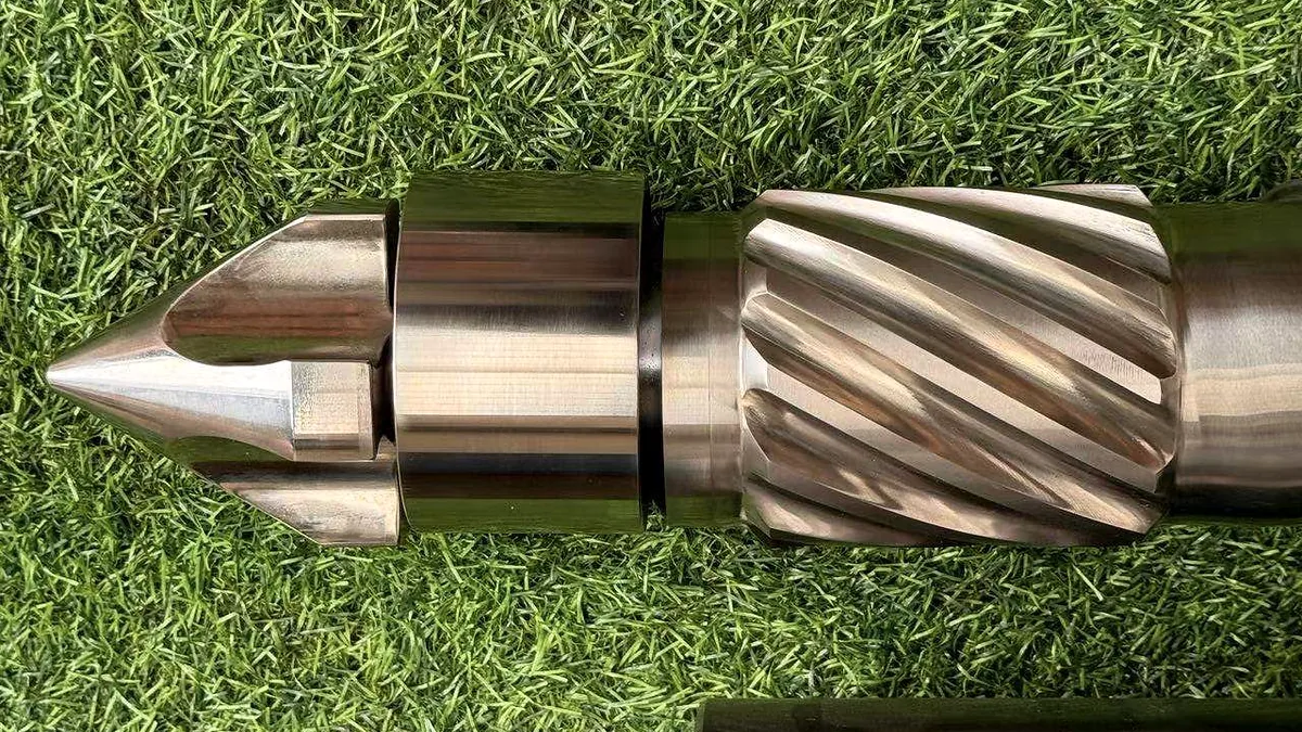
Stop Wasting Resin: How Mechanical Purging Compound Actually Works
Nov 5, 2026
Learn how mechanical purging compounds use shear force, high viscosity, and abrasive fillers to clean barrels. Covers dosage, procedures, resin matching, and maintenance tips.
Read ArticleLooking for something else?
Search by material, symptom or product and jump straight to the relevant page.
These are navigation suggestions based on keyword matching — not a quotation, not a delivery commitment, and not a substitute for engineering review. Final specification is confirmed by our engineers against your drawings and processed material.
Need help with screw barrel selection?
Share your machine model, processed material and application. Our team can help with pricing and technical support.