

What Purging Plastic Means and Why Every Processor Should Care
Black specks on a finished part. Color streaks that refuse to disappear. Scrap bins filling up during every changeover. If any of this sounds familiar, your purging process deserves more than a quick barrel flush and a shrug.
Defining Purging Plastic in Modern Processing
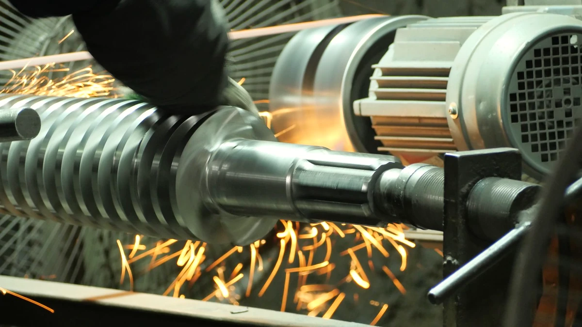
Purging plastic is the controlled displacement of residual resin, colorant, degraded polymer, or additive buildup from the barrel, screw, check ring, nozzle, and melt-delivery components of a plastics processing machine—performed before, during, or after a production run to restore a clean melt path.
That definition matters because it reframes what many plants treat as a reactive chore into what it actually is: a process-critical operation. Every time purging material moves through the plasticizing system, it is either recovering lost capacity or preventing the next wave of rejects.
So why does contamination build up in the first place? Three mechanisms drive most of the trouble. First, thermal degradation—heat slowly breaks polymer chains into carbonized residue, especially during shutdowns, startups, and extended idle periods. Second, pigment adhesion—colorants cling to screw flights, barrel walls, and check-ring surfaces where shear is low. Third, resin decomposition in dead spots—areas of stagnant flow inside the compression zone, behind worn non-return valves, or within hot-runner manifolds where material sits long enough to degrade. These residues do not flush out on their own; they require deliberate removal using purge compounds engineered for the task or, in severe cases, manual disassembly.
The Hidden Cost of Skipping or Rushing a Purge
Imagine tracking every minute a machine sits idle during a color change, every rejected part pulled off the line after startup, and every kilogram of purging compounds or virgin resin consumed without a clear procedure. The real expense of poor purging shows up across several dimensions:
- Changeover scrap rate — parts produced between the end of one run and the start of acceptable quality on the next.
- Hourly machine downtime cost — lost production capacity while the barrel is being cleaned.
- Labor time — operators manually cycling, inspecting slugs, and troubleshooting contamination.
- Quality rejects downstream — specks or streaks that slip past initial inspection and trigger customer returns.
When you add these factors together for your own operation, the picture shifts quickly. Purging stops looking like a maintenance expense and starts looking like an investment with a measurable return in uptime, yield, and consistency.
Who This Guide Serves
This guide is built for injection molding operators, extrusion technicians, process engineers, maintenance teams, and plant managers who want a vendor-neutral, engineering-focused resource. Whether you are evaluating purging compounds for the first time or trying to understand why your current approach still leaves carbon behind, the sections ahead cover the full picture—from the science of contamination removal to hardware conditions that silently undermine every purge cycle you run.
The Science Behind How Purging Compounds Remove Contamination
Knowing that contamination accumulates is one thing. Understanding exactly how purging agents strip it from metal surfaces is what separates a quick barrel flush from a genuinely effective cleaning cycle. Most processors pick a compound, run it through, and hope for the best. A sharper approach starts with the cleaning mechanism itself—because the way a compound removes residue determines whether it actually works against the specific contaminant you are fighting.
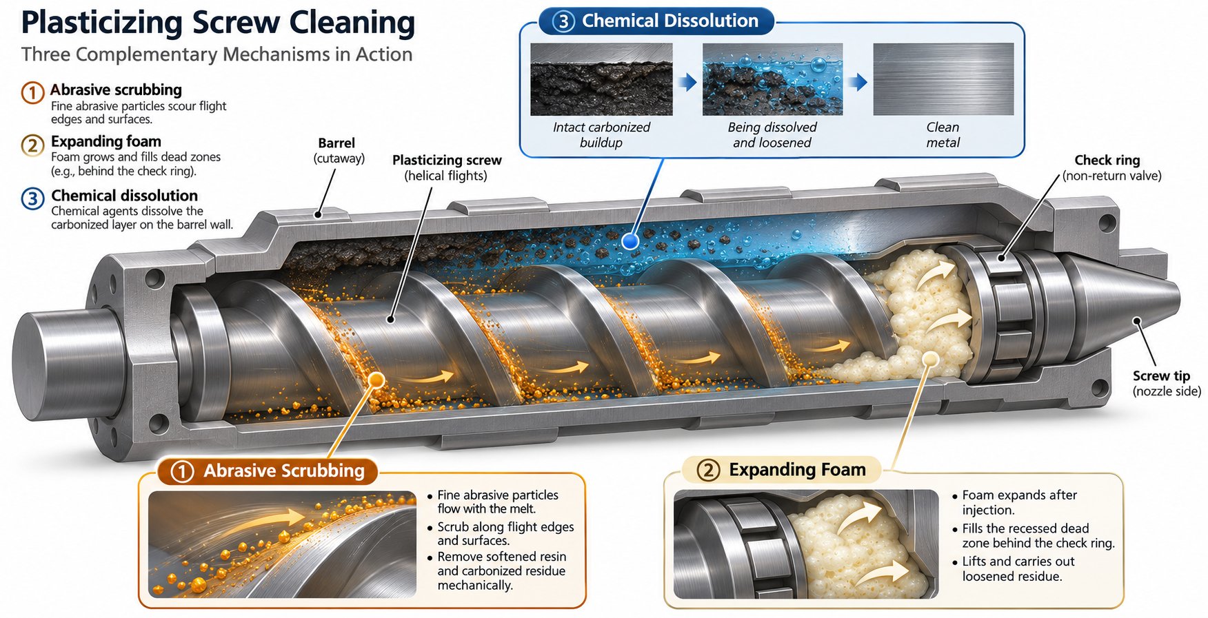
Three core mechanisms drive contamination removal in modern purge compounds: mechanical scrubbing, chemical reaction, and foaming expansion. Each one targets a different type of deposit, and each behaves differently inside the barrel, screw flights, and downstream melt-delivery components. When you match the mechanism to the problem, changeovers get faster and results become repeatable.
Mechanical Scrubbing Action Explained
Picture a high-viscosity carrier resin being forced through the tight clearance between your screw flights and the barrel wall. That is the basic principle behind mechanical purging. These compounds rely on shear, pressure, and physical agitation rather than any chemical reaction to dislodge contaminants.
Here is how it works at the metal surface. The carrier resin in a mechanical purge is formulated with a higher melt viscosity than typical processing resins. As the screw rotates, this thicker melt generates elevated shear stress against the barrel bore and flight edges—physically scraping and dragging deposits off the steel. Some formulations also incorporate abrasive or high-detergency additives that boost this scrubbing power, increasing the compound's ability to wet and lift residues rather than slide over them.
You'll notice the biggest impact during purge injection molding applications where active screw rotation provides consistent mechanical energy. The screw's compression zone, where flight depth decreases and melt pressure rises, becomes the primary cleaning area. Deposits trapped along the trailing edges of flights and in the metering section get sheared loose as the high-viscosity compound is driven forward under pressure.
The limitation? Mechanical compounds depend on direct contact. Any area the melt stream bypasses—narrow hot-runner channels, stagnant pockets behind worn check rings, or dead zones in manifold branches—may not receive enough shear force for a thorough clean. That is exactly where the next mechanism steps in.
Chemical Cleaning and Foaming Mechanisms
Chemical purging agents take a fundamentally different approach. Instead of relying solely on physical force, they use thermal chemical reactions to break molecular bonds in degraded residue. When these compounds reach processing temperature, active cleaning agents in the formulation react and generate gases that expand within the melt. This expansion creates internal pressure that pushes the compound into tight, low-flow areas conventional mechanical compounds simply cannot reach.
Imagine a thin film of carbonized resin baked onto the interior wall of a hot-runner manifold branch. A mechanical compound flowing through the main channel may never contact that film with enough force to remove it. A chemical purge, however, expands at temperature and presses outward against those walls, penetrating dead zones in check rings, metering sections, and nozzle tips where degraded material hides.
Foaming agents—often built into hybrid formulations—amplify this effect. As the compound heats up, controlled gas generation causes it to swell, filling voids and increasing contact area with contaminated surfaces. The combination of chemical bond-breaking and physical expansion makes these purging agents especially effective for purging extruders with long, complex flow paths, blown film dies with tight land lengths, and multi-zone hot-runner systems where flow stagnation is common.
There is a trade-off worth noting. Chemical and foaming compounds sometimes leave their own residue behind, which means a short follow-up displacement purge with virgin resin or a compatible mechanical compound may be necessary before starting production. They also require tighter temperature control—run them too cool and the reaction underperforms; run them too hot and the compound itself can degrade, creating new contamination rather than removing old deposits.
How Contaminant Type Dictates Mechanism Choice
Here is where the science becomes directly practical. The type of residue stuck inside your barrel should drive your choice of purging mechanism—not habit, not convenience, and not whatever compound happens to be sitting on the shelf. Each contaminant responds differently to mechanical force, chemical action, and foaming expansion.
| Contaminant Type | Recommended Mechanism | Why It Works |
|---|---|---|
| Carbon buildup (black specks) | Chemical or hybrid (foaming) | Carbonized deposits are baked-on residue with strong adhesion to metal. Chemical agents break molecular bonds in the degraded layer, while foaming expansion reaches stagnant zones where carbon accumulates most heavily. |
| Color pigment residue | Mechanical (high-viscosity scrubbing) | Pigments cling to screw flights and barrel walls through surface adhesion. High shear stress and strong wetting action from a viscous carrier physically shear pigment films off steel surfaces more efficiently than chemical reaction alone. |
| Degraded polymer film | Chemical or hybrid | Thin polymer films baked onto metal resist mechanical removal because they conform tightly to surface geometry. Chemical agents that react at processing temperature soften and lift these films by attacking the degraded polymer chains directly. |
| Flame-retardant residue | Hybrid (chemical + foaming) | Flame-retardant additives can plate out as tenacious films in low-flow areas. Hybrid compounds combine chemical deposit lift with foaming expansion, increasing contact in dead zones where these residues concentrate. |
A few guiding principles tie this table together. When contamination is surface-adhesion driven—like pigment clinging to metal—mechanical shear is your first tool. When contamination is thermally degraded and bonded at a molecular level—like carbon or decomposed polymer—chemical action is more effective. And when the contamination sits in areas the main melt stream does not reach, foaming expansion is often the only mechanism that makes meaningful contact.
Matching the mechanism to the contaminant is half the equation. The other half is matching your purging method to your specific process, resin family, and machine configuration—factors that vary widely between a simple commodity-resin color change and a full transition from an engineering-grade polymer down to polyethylene.
Every Purging Method Compared: Types of Purging Compounds and Beyond
Knowing which cleaning mechanism removes a given contaminant solves one piece of the puzzle. The next question is equally important: which purging method should you actually use? The answer depends on your resin, your contamination severity, your quality tolerance for the next run, and how much downtime your schedule can absorb. Processors typically choose from six distinct approaches—ranging from a basic resin flush that costs almost nothing up front to a full screw pull that eats an entire shift. Each method occupies a specific place in the toolbox, and understanding the types of purging compounds alongside non-compound methods helps you pick the right one every time.
Virgin Resin Flushing and Regrind Purging
These are the methods most processors try first, and for good reason—they require zero special materials. You simply feed virgin resin or regrind through the barrel and let volume do the work. For a minor color change between similar commodity resins, say switching from one shade of polypropylene to another, a virgin resin flush can get the job done.
The problems start when you ask it to do more than that. Commodity resins lack the viscosity, the scrubbing additives, and the chemical activity needed to remove anything bonded to the barrel wall or lodged in a low-flow zone. A Plastics Technology roundtable featuring purging specialists and machinery manufacturers reinforced this point directly: production resin, regrind, and additives are not a substitute for commercial purging compounds because they simply lack the cleaning power to drag stubborn colorants and carbon out of dead zones.
Think about it this way—flushing with virgin resin is like rinsing a greasy pan under cold water without soap. The surface looks cleaner, but a layer of residue stays behind, ready to contaminate the next run. You'll often waste hundreds of pounds of material and significant machine time only to find color streaks or specks still showing up in your startup parts. Regrind performs even worse because it may carry its own contaminants back into the barrel.
When do these low-cost approaches make sense? In two narrow scenarios: light-to-dark color transitions where minor carryover is acceptable, and quick displacement between chemically similar resins at similar processing temperatures. Outside those windows, you are spending more on wasted resin and lost production time than a dedicated purge compound would cost.
Mechanical, Chemical, and Hybrid Compounds Compared
Step beyond virgin resin and regrind and you enter the world of purpose-built purge compound formulations—mechanical, chemical, and hybrid. Each one is engineered to solve cleaning problems that production resin cannot touch, but they differ significantly in how they work, where they excel, and what they cost relative to one another.
A concentrated purging compound in the mechanical category relies on high-viscosity carriers and scrubbing agents that physically shear deposits off metal surfaces. A chemical purging formulation uses reactive agents that break molecular bonds in degraded residue at processing temperature. Hybrid and foaming compounds combine both principles, adding controlled gas generation to expand into dead zones that neither pure mechanical nor pure chemical compounds reach alone.
The table below lays out all six methods side by side so you can compare them on a level playing field. No brand names, no proprietary data—just the engineering principles behind each approach.
| Method | How It Works | Best Use Case | Limitations | Relative Cost | Typical Downtime Impact |
|---|---|---|---|---|---|
| Virgin Resin Flushing | Pushes fresh resin through the barrel to displace residual material by volume alone | Light-to-dark color changes between similar commodity resins | No scrubbing or chemical action; ineffective against carbon, degraded polymer, or tenacious pigments; high material waste | Low per pound, but high total cost due to volume needed | High — slow displacement extends changeover time significantly |
| Regrind Purging | Uses recycled production material to flush the barrel, relying on volume and abrasiveness of regrind particles | Non-critical transitions where minor contamination is acceptable | May reintroduce contaminants; inconsistent particle size reduces effectiveness; cannot remove bonded residue | Lowest (uses existing scrap) | High — similar to virgin flush with less predictable results |
| Mechanical Purge Compound | High-viscosity carrier with scrubbing agents generates elevated shear stress to physically remove deposits from barrel and screw surfaces | Pigment changes, routine changeovers, broad polymer compatibility | Requires direct melt contact; less effective in dead zones, narrow hot-runner channels, or behind worn check rings | Medium | Low to moderate — typically cleans faster than resin flush with less material |
| Chemical Purging Compound | Reactive agents activated at processing temperature break molecular bonds in degraded residue; some generate gas to increase pressure in low-flow zones | Carbon buildup, degraded polymer films, baked-on residue in stagnant areas | Requires precise temperature control; may leave own residue requiring follow-up flush; not compatible with all resins | Medium to high | Low — effective cleaning in fewer cycles when matched to the right contaminant |
| Hybrid / Foaming Compound | Combines mechanical scrubbing with chemical reaction and controlled foaming expansion to clean both high-flow and stagnant areas | Severe contamination; hot-runner manifolds; flame-retardant residue; dark-to-light transitions on complex tooling | Higher cost per pound; requires careful temperature management; follow-up displacement purge often needed | High | Low — addresses multiple contamination types in a single cycle |
| Manual Disassembly (Teardown) | Physical removal and hand-cleaning of barrel, screw, check ring, nozzle, and hot-runner components using brass tools and approved solvents | Severe carbon encrustation; worn or damaged hardware creating permanent dead zones; situations where compounds repeatedly fail | Labor-intensive; extended downtime; risk of damage during reassembly if procedures are not followed carefully | High (labor hours) | Very high — typically 2 to 8+ hours depending on machine size and severity |
A few patterns jump out of this comparison. Virgin resin and regrind cost the least per pound but often produce the longest changeovers and highest total waste. Dedicated purge compounds—whether mechanical, chemical, or hybrid—cost more per pound but dramatically reduce the volume needed and the time spent, which is exactly why purging specialists emphasize that machine downtime, not material cost per pound, is the primary driver of changeover expense. And manual teardown sits at the far end of the spectrum: highest cost in labor and downtime, but sometimes the only method that actually solves the problem.
When Manual Disassembly Is the Only Answer
No purge compound—no matter how advanced the formulation—can fix a problem that lives in the hardware itself. There is a decision threshold every processor eventually hits where running another purge cycle is just burning material and time without moving any closer to a clean barrel.
When does that threshold arrive? Experienced maintenance teams learn to spot the warning signs early. If you are seeing any of the following patterns, it is time to stop purging and start planning a teardown:
- Escalating compound consumption — you need noticeably more purge compound each cycle to achieve the same level of cleanliness you used to reach with less.
- Persistent specks after multiple purge cycles — black specks or color contamination keeps returning within minutes of restarting production, even after a thorough purge using the correct compound and technique.
- Rising scrap rates post-purge — your startup reject count trends upward over weeks or months despite consistent purging procedures.
- Visible wear on pulled screws — when screws are eventually removed for inspection, you see worn flight edges, scoring on the barrel bore, or check-ring components with obvious erosion or pitting.
- Carbon or residue returning from the same location — specks consistently originate from a specific zone, such as the check-ring area or a particular hot-runner drop, suggesting a permanent dead spot that compounds flow past rather than through.
- Purge compound exiting with metal particles — metallic flecks in the purge stream indicate screw or barrel wear has progressed to the point where the hardware is generating its own contamination.
A manual teardown carried out with proper technique—brass tools only, cleaning while the polymer is still in a melt state, and careful photographic documentation of element order before disassembly—resolves what compounds cannot. It gives your team direct visual access to the screw flights, barrel bore, check ring, end cap, and nozzle interior where hidden damage or carbon encrustation lives.
The critical takeaway here is knowing where the compound stops and the wrench starts. Processors who push past that threshold waste material, lose hours of production, and still end up pulling the screw anyway. Recognizing the warning signs early turns teardown from an emergency into a planned maintenance event—and that distinction alone saves significant downtime and frustration.
Choosing among these six methods is a strong starting point. Yet even the best method selection falls short if the purge compound you pick does not match the resin family you are running—or the resin you are transitioning into. Temperature compatibility, chemical interactions, and the gap between outgoing and incoming polymers all shape whether a purge cycle succeeds or fails before the first pellet ever enters the barrel.
Selecting the Right Purging Agent for Every Resin Transition
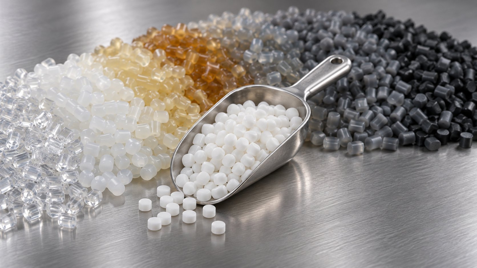
You have picked the right purging method. You understand whether mechanical scrubbing, chemical action, or a hybrid approach fits your contamination type. So why does the changeover still leave streaks in the first fifty shots? In most cases, the answer is not the mechanism—it is the match between the purging compound and the specific resins involved in the transition.
Resin-to-resin compatibility is the variable that separates a textbook color change from a frustrating hour of scrap and rework. Temperature processing windows, chemical interactions, filler content, and the gap between the outgoing and incoming polymer all influence whether a purging agent can do its job—or whether it creates new problems. This section maps those variables into a practical reference you can use the next time you stand at the hopper deciding what to run through the barrel first.
Matching Purging Compounds to Resin Families
Every purging compound has a stated processing temperature range. Step outside that range and performance drops fast—too cool and the compound does not develop enough viscosity or chemical activity to clean; too hot and the compound itself degrades inside the barrel. Your first compatibility check, then, is simple: does the compound's temperature window overlap with both the outgoing resin's melt temperature and the incoming resin's melt temperature?
Beyond temperature, chemical compatibility matters more than many processors realize. A cautionary example comes from injection molding safety expert John Bozzelli, who has documented cases where mixing acetal (POM) with PVC—even in small residual amounts left on screw flights after purging—triggers violent decomposition. The gases generated can blow endcaps through walls and hoppers through roofs. That is an extreme case, but it underscores a principle that applies across the board: certain resin families and certain chemical purging agents are simply incompatible, and no amount of careful technique fixes a bad pairing.
For optical-grade or medical-grade applications, compound selection narrows further. Packaging purging compounds suitable for food-contact or FDA-regulated environments must leave zero residue that could migrate into the final part. That typically rules out heavily loaded chemical formulations in favor of ultra-clean mechanical compounds specifically certified for sensitive applications.
The table below organizes the most common resin transition categories alongside general guidance on purging approach, temperature considerations, and risk factors. Use it as a starting framework, not as a substitute for your compound supplier's specific compatibility data.
| Resin Transition Category | Recommended Purging Approach | Key Temperature Considerations | Risk Factors |
|---|---|---|---|
| Engineering-to-commodity (e.g., PEEK, PEI, or PPS down to PP or PE) | Stepped purge: intermediate bridge resin at a mid-range temperature, followed by a mechanical or hybrid purging compound matched to the incoming commodity resin | Temperature delta can exceed 200 °F (110 °C). Dropping barrel temps too fast traps high-temp residue as solidified deposits. Stage temps downward gradually during the bridge step. | Residual engineering resin carbonizes rapidly at commodity processing temps if not fully displaced. Incomplete purging creates persistent black specks in subsequent runs. |
| Commodity-to-commodity (e.g., PP to PE, PS to ABS) | Mechanical purging compound; virgin resin flush may suffice for same-family transitions with minimal color delta | Temperature gap is typically small (under 50 °F / 28 °C). Match barrel setpoint to whichever resin has the higher processing temp during the purge cycle. | Low risk overall, but dark-to-light color changes within this category still require a dedicated compound rather than a simple resin flush. |
| Filled-to-unfilled (e.g., glass-filled nylon to unfilled nylon or PP) | Mechanical purging compound with strong displacement properties; avoid low-viscosity compounds that flow around trapped filler strands | Process at the filled material's temperature during the purge to keep residual filler mobile, then reduce temps for the incoming unfilled resin. | Glass fibers and mineral fillers embed in worn screw-flight edges and barrel scoring. If filler carryover persists after purging, hardware wear is likely the root cause. |
| Dark-to-light color change | High-viscosity mechanical compound or hybrid (foaming) compound for maximum pigment displacement | Maintain the outgoing resin's processing temp during initial purge cycles to keep pigment mobile and easier to displace. | Pigment trapped behind worn check rings or in hot-runner dead zones will reappear as streaks in the light-colored run. Multiple short purge shots with screw-speed variation outperform a single long flush. |
| Flame-retardant compound to standard resin | Hybrid or chemical compound to break down FR additive plate-out in stagnant zones, followed by mechanical displacement | FR compounds often process at elevated temps. Purge at or slightly above the FR material's processing temp to mobilize residue before transitioning downward. | FR additives plate out aggressively in low-flow areas. Residual FR chemistry can affect surface quality, adhesion, and regulatory compliance of the incoming resin. Mold purging after barrel purging is recommended. |
A pattern emerges across every row: the wider the gap between the outgoing and incoming resins—in temperature, viscosity, filler content, or additive chemistry—the more aggressive and deliberate your purging strategy needs to be.
High-Temperature and Specialty Resin Challenges
Imagine you have just finished a PEEK production run at 720 °F (382 °C) and your next job calls for polypropylene at 420 °F (216 °C). Dropping the barrel temperature by 300 °F and hoping the incoming PP flushes out the PEEK is a recipe for disaster. Residual PEEK solidifies into a hard shell on barrel walls and screw flights the moment temperatures drop below its crystallization point. That shell becomes a persistent contamination source—carbon specks, degraded flakes, and color contamination that no amount of PP will dislodge.
This is exactly why experienced processors use a stepped-purge strategy for large temperature deltas. The concept is straightforward:
- Step 1: While the barrel is still at the high-temperature resin's setpoint, run a purging compound rated for that temperature range to displace as much of the engineering resin as possible.
- Step 2: Introduce a bridge resin—a thermally stable, mid-range polymer like HDPE or a general-purpose purge grade—and begin staging barrel temperatures downward in increments of 25-50 °F (14-28 °C).
- Step 3: Once barrel temps reach the processing window for the incoming commodity resin, run a second purging cycle using a compound matched to the lower temperature range.
- Step 4: Introduce the production resin and verify part quality before committing to full-rate production.
The bridge step is the piece most plants skip—and the step that prevents the majority of post-changeover contamination events. Without it, you are asking a low-temperature purging compound to clean a barrel that still contains high-temperature residue it cannot soften, let alone remove.
Glass-filled and mineral-filled engineering resins add another layer of difficulty. Filler particles wedge into surface imperfections on the screw and barrel, and they resist displacement by purging compounds alone. If your facility frequently transitions between filled engineering grades and unfilled commodity materials, monitoring screw and barrel wear becomes essential. Abrasive fillers accelerate wear, wear creates dead zones, and dead zones undermine every purge cycle that follows.
Compound Selection Decision Framework
With so many variables in play—resin families, temperature gaps, filler content, additive chemistry, and quality requirements—a systematic approach beats guesswork every time. The following decision framework walks you through compound selection step by step, using the same logic a process engineer would apply on the floor:
- Identify the outgoing resin family and its processing temperature. This sets the upper boundary for your purging compound's temperature range. If the outgoing material is above 600 °F (315 °C), plan for a stepped purge with a bridge resin.
- Identify the incoming resin family and its processing temperature. Calculate the temperature delta. Transitions with a gap exceeding 100 °F (55 °C) almost always require staged temperature reduction and may need two different purging compounds.
- Assess filler and additive content. Glass-filled, mineral-filled, or flame-retardant-loaded outgoing resins demand higher-viscosity mechanical or hybrid compounds to displace embedded particles and plate-out residue. Standard resin flushes are not sufficient.
- Evaluate contamination severity. Is this a routine scheduled changeover with minimal residue, or are you dealing with carbon buildup from an extended run or an unplanned shutdown? Heavier contamination shifts the recommendation from mechanical toward chemical or hybrid compounds.
- Determine the quality tolerance of the next production run. Optical parts, medical devices, and light-colored packaging demand near-zero carryover. For these applications, select a compound certified for the end-use environment and plan for post-purge quality verification—visual inspection of slugs at minimum, spectrometer checks if available.
- Check for absolute chemical incompatibilities. Before any resin enters the barrel, confirm that the outgoing resin, the purging compound, and the incoming resin are chemically safe together. POM with PVC is the most dangerous pairing, but other combinations—such as certain chemical purging agents with moisture-sensitive resins—can cause degradation, off-gassing, or surface defects.
- Document the procedure and results. Record the compound used, temperatures at each stage, number of purge cycles, slug inspection results, and startup scrap count. This data builds the historical baseline that makes every future transition faster and more predictable.
Running through these seven steps takes less time than a single wasted purge cycle—and it removes the trial-and-error approach that turns a fifteen-minute changeover into a forty-five-minute headache.
Resin compatibility and compound selection lay the groundwork for an effective purge, yet the conversation has focused almost entirely on the barrel and screw so far. Many processors discover that their worst contamination problems originate not in the barrel at all, but in the hot-runner manifold, the extrusion die, or the accumulator head of a blow molding machine—equipment with its own unique dead zones and flow challenges that standard barrel-purging procedures barely touch.
Purging Across Injection Molding, Extrusion, and Blow Molding
Hot-runner manifolds, flat dies, accumulator heads, blown film air rings—every plastics process shapes the melt path differently, and every unique geometry creates its own hiding spots for degraded material. A purging procedure that works perfectly on a simple open-nozzle injection press may accomplish almost nothing on a twin-screw compounding extruder or a large accumulator-head blow molder. Purging compound selection and execution technique both need to flex around the machine in front of you, not the other way around.
This section walks through the process-specific challenges and step-by-step sequences for the three major process families—injection molding, extrusion (including blown film and compounding), and blow molding—so you can adapt your approach to whatever equipment is on your floor.
Purging in Injection Molding and Hot-Runner Systems
Injection molding is where most processors first encounter purging plastic, and for good reason. Frequent color changes, tight quality tolerances, and multi-cavity tooling with complex hot-runner manifolds make contamination a constant threat. The challenge is that the barrel is only one piece of the flow path. Between the hopper throat and the cavity gate, the melt passes through the screw's compression and metering zones, past the check ring, through the nozzle tip, into the manifold, down individual drops, and finally through valve gates or thermal gates into the mold. Contamination can stall at any point along that chain.
A structured purging sequence addresses each zone in order, starting upstream and working downstream:
- Barrel purge. Empty the hopper of production resin. Introduce the purging material for injection moulding at the correct processing temperature. Run a series of screw-recovery and injection cycles at moderate to high screw speed, varying the RPM between cycles to change the shear profile inside the barrel. This variation dislodges pigment and carbon from different flight surfaces rather than just sweeping the same central flow channel.
- Nozzle purge. Retract the injection unit from the mold. Perform several high-velocity free-air purge shots through the nozzle to clear residue from the nozzle bore and tip. Watch the extrudate color—when it transitions cleanly, the nozzle is clear.
- Hot-runner flush. Reconnect to the mold and inject the purging compound directly into the hot-runner system. Here is where technique matters most. Industry purging specialists recommend using short, high-velocity shots to promote turbulence inside the manifold rather than slow, steady fills that let the compound take the path of least resistance. If specific gates show persistent streaking, close off all other gates and shoot high-velocity short shots through each affected drop one at a time to concentrate cleaning force where it is needed.
A few critical details separate a clean hot-runner purge from a wasted one. Always confirm that the purging compound grade you are using is rated for hot-runner use—not all formulations clear narrow gate restrictions without plugging. Glass-filled mechanical compounds are generally not suitable for hot runners or highly polished molds. And if your system has low-flow zones created by poor manifold design, a chemical compound with foaming action can expand into those dead spots and pull away contamination that mechanical compounds flow right past.
One more point worth emphasizing: sealing the hot runner during extended shutdowns—weekends, holidays, planned maintenance—prevents oxygen from entering the manifold channels and accelerating carbonization. Processors who skip this step often face severe startup contamination that takes far more purging compound to resolve than the sealing step would have consumed.
Purging Extruders and Blown Film Lines
Move from injection molding to extrusion and the contamination profile changes significantly. Extruders run continuously, often for days or weeks at a stretch. There is no check ring and no hot-runner manifold. Instead, you have a long barrel with a deep feed zone, compression zone, and metering zone feeding into a die—flat, annular, or profile—with its own internal flow channels, land lengths, and potential dead spots.
Single-screw extruders accumulate contamination primarily in the compression zone, where flight depth decreases and melt pressure rises. Degraded polymer films build up on the trailing edges of flights and along the barrel wall in areas of low shear. Twin-screw extruders—especially co-rotating intermeshing designs used in compounding—present a more complex picture. Kneading blocks, mixing elements, and the tight clearances between the two screws create dozens of small zones where material can stagnate and degrade. As veteran twin-screw field technicians point out, carbon has a strong affinity for metal, so degraded polymer builds up in layers and then breaks free downstream, contaminating product long after the original material is gone.
Purging compounds for extrusion require a different approach than injection molding procedures. Here is the general sequence:
- Increase screw speed gradually as you introduce the purging compound. Higher RPM generates more shear at the barrel wall and flight surfaces, improving the mechanical scrubbing effect. On twin-screw systems, varying speed throughout the purge cycle—sometimes called a "disco purge"—changes the shear pattern and reaches areas a steady speed would miss.
- Stage temperatures deliberately. If you are transitioning from a high-temperature resin to a lower one, do not drop barrel temps all at once. Reduce zone by zone, starting at the die end and working back toward the feed throat. This keeps residual resin mobile long enough for the purging compound to displace it rather than letting it solidify in place.
- Dose the compound correctly. Overloading the barrel wastes material; underloading means the compound never generates enough melt pressure to scrub effectively. Most commercial purging compounds for extrusion include dosing guidelines based on barrel diameter and L/D ratio—follow them as a baseline, then adjust based on the color and consistency of the extrudate.
- Address the die and screen pack. The barrel is only half the system. Die lips, land channels, and screen packs trap residue that barrel-focused purging does not reach. After the barrel purge, inspect the screen pack for discoloration or embedded carbon. Replace it if contamination is visible. Run additional purging compound through the die at elevated back pressure to flush internal channels before introducing production resin.
Blown film lines add yet another layer of complexity. The annular die distributes melt in a spiral or coat-hanger pattern, and even small amounts of residual pigment or degraded polymer in one section of the spiral create visible streaks in the film bubble. Maintaining bubble stability during purging requires careful balance—too aggressive a screw-speed change and the bubble collapses; too gentle and the purge never cleans the die's internal distribution channels. Many operators find that running the purging compound at slightly higher output rates than normal production, while making small adjustments to the air ring, produces the best balance of cleaning effectiveness and bubble stability.
Blow Molding and Profile Extrusion Purging
Accumulator-head blow molding machines present some of the most difficult purging challenges in all of plastics processing. Unlike continuous extrusion or cyclic injection, accumulator-head systems store melt in a large chamber before pushing it out in a single shot to form the parison. That storage phase creates a low-pressure zone where resin sits with minimal flow—exactly the conditions that promote degradation and carbon buildup.
HDPE and PP compounds, the workhorses of large blow-molded containers and industrial drums, tend to layer inside the accumulator over time. When the machine cycles, degraded material breaks loose and contaminates the parison, producing die lines, burn streaks, and surface defects. Blow molding purging experts stress that the extruder barrel must be cleaned first—if the screw is still contaminated, you are simply feeding new residue into the accumulator head with every cycle.
Profile extrusion shares some of these difficulties. Complex die geometries with thin land sections and internal flow dividers create pockets where material hangs up. Color changes on profile lines often take far longer than processors expect because the die—not the barrel—is the contamination bottleneck.
Here are process-specific tips for each method:
- Accumulator blow molding: After cleaning the extruder barrel, fill the accumulator with purging compound at 25% capacity and push a shot. Increase to 50%, then 75%, then full capacity over successive cycles. This staged approach forces compound contact across the full interior surface of the accumulator chamber rather than just the central flow path. Vary screw speed during the fill phase to change shear conditions and improve scrubbing.
- Continuous extrusion blow molding: Purge the extruder using the speed-variation and temperature-staging method described above. Focus on the crosshead die by running the compound at higher-than-normal back pressure to push material through tight annular gaps. Inspect parison quality visually after each cycle—streaks in the parison mean the die still holds residue.
- Profile extrusion: Run the purging compound at the processing temperature of the outgoing resin. Use short, high-output bursts alternating with brief pauses (soak time) to let chemical or foaming compounds expand into the die's internal channels. After purging, remove and inspect the die plate and calibration tooling for embedded residue that barrel-side purging cannot reach.
- Blown film (annular die): Purge the extruder first, then continue running the compound through the die at a slightly elevated output rate. Watch the bubble for streak-free uniformity before switching to production resin. If persistent streaks appear in one section of the bubble, the die's spiral mandrel or distribution channel may need disassembly and manual cleaning.
- Shutdown sealing (all blow molding and extrusion): Before any extended downtime, seal the barrel, die, and accumulator (if present) with a shutdown-rated purging compound. This displaces heat-sensitive resin that would otherwise oxidize and carbonize during the idle period, dramatically reducing startup scrap.
Across every one of these processes, one truth remains constant: the purging compound can only clean surfaces it actually contacts. When contamination persists despite correct compound selection and thorough technique, the problem usually is not the compound—it is the hardware underneath. Worn screw flights, eroded barrel bores, and damaged check rings create permanent dead zones that no purging procedure, no matter how well executed, can fully resolve.
How Screw, Barrel, and Check-Ring Wear Undermines Purging Results
You have selected the right purging compound. You have matched the mechanism to the contaminant type. Your operator followed a documented procedure with correct temperatures, screw-speed variation, and soak times. And yet black specks keep coming back within thirty minutes of restarting production.
Sound familiar? Before blaming the compound or the technique, look deeper—literally. The physical condition of the plasticizing hardware sitting inside your barrel sets a hard ceiling on how effective any injection molding purging method can ever be. Worn screw flights, an eroded barrel bore, a damaged check ring, or a pitted end cap can silently turn a textbook purge cycle into an exercise in futility. This is the variable almost no one talks about, and it explains a huge share of the "we tried everything" contamination failures that frustrate process engineers and maintenance teams alike.
Why Worn Screws and Barrels Create Purging Dead Zones
Imagine the screw rotating inside the barrel as a tightly fitted piston in a cylinder. When both components are new, the clearance between the outer edge of the screw flight and the barrel wall is deliberately minimal—typically just a few thousandths of an inch. That tight gap is what forces the melt to travel forward along the flight channel under pressure, generating the shear stress that both processes the resin and, during a purge, scrubs contamination off metal surfaces.
As the flight edges wear down over thousands of processing hours, that clearance grows. The consequences cascade quickly:
- Melt leakage over the flights. Resin slips backward over the worn flight edges rather than being pushed forward. Some of that leaked material pools in low-pressure pockets along the barrel wall—areas the main melt stream no longer sweeps clean. These stagnant pools degrade thermally, carbonize, and eventually shed black specks into the flow.
- Reduced shear stress. A wider gap between flight and barrel means less mechanical work on the melt. Purging compounds—especially mechanical formulations that rely on high viscosity and shear to scrub surfaces—lose a significant portion of their cleaning power because the compound flows through the enlarged clearance instead of being forced against the barrel wall.
- Altered compression ratio. Screw wear does not happen uniformly. The compression zone and metering section experience the most abrasive contact, so they wear fastest. As flight depth changes unevenly, the compression ratio the screw was originally designed to deliver shifts. Lower effective compression means lower melt pressure in the metering zone, which further reduces the scrubbing force available during purging.
Barrel bore wear compounds the problem from the other side. Maintenance guidance from plastics equipment specialists emphasizes that worn barrels lead to uneven heat distribution, temperature fluctuations, and inconsistent material flow—all of which degrade both processing quality and purging effectiveness. Pitting, scoring, and erosion of the barrel liner create microscopic crevices where degraded resin lodges permanently. No purging compound can reach inside a pit that is smaller than the compound's particle or melt-film thickness. That residue stays put, slowly carbonizing and periodically releasing specks into your product stream.
The combined effect is a plasticizing system that looks functional from the outside—the screw turns, the machine cycles, parts come out—but harbors hidden contamination reservoirs that no injection mold purging compound can fully access.
Check-Ring and End-Cap Wear as Hidden Contamination Sources
If the screw and barrel create the most widespread dead zones, the check ring and end cap create the most stubborn ones. These components sit at the very front of the screw assembly, directly in the path of every shot. Their job is straightforward: allow melt to flow forward during screw recovery, then seal to prevent backflow during injection. When they do that job cleanly, material residence time in the check-ring area stays short and predictable.
When they wear? The story changes dramatically.
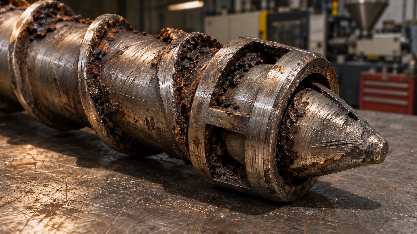
A worn check ring no longer seats flush against its mating surface. Small gaps open between the ring's sealing face and the end cap, creating backflow pockets where resin reverses direction and stagnates during injection. Contamination analysis from purging specialists confirms that these internal leaks—caused by worn screw and barrel assemblies, damaged check rings, and loose components—trap resin in locations isolated from normal material flow. Because fresh resin does not continuously sweep through these pockets, the trapped material degrades over hours and days, forming carbonized deposits that periodically break loose and enter the melt stream as intermittent black specks.
Here is what makes this so frustrating to diagnose: the contamination appears sporadically. You purge the barrel, start production, run clean for twenty or thirty minutes, and then specks reappear without warning. The purge did remove the loose carbon in the main flow path. But the worn check ring keeps generating new carbon in its backflow pocket, and no purging compound flowing through the barrel can reach that pocket effectively—the compound follows the main melt channel, while the stagnant pocket sits in a hydraulic shadow behind the worn seal.
End-cap erosion follows the same pattern. Pitted or scored end-cap surfaces create micro-cavities where resin hangs up and cooks. Operators may not even inspect these components unless they pull the screw for maintenance, which means the contamination source can persist for months—silently degrading product quality and driving up scrap rates while the team chases the problem with more compound, higher temperatures, and longer purge cycles that never quite solve it.
Recognizing When Hardware Replacement Outperforms Repeated Purging
There comes a point where spending more on purging compound is not just ineffective—it is actively wasteful. The contamination source has moved from "residue on a surface" to "residue generated by the surface itself." Recognizing that threshold early saves material, time, and a lot of frustration.
Use the following diagnostic checklist. If two or more of these signs are present, the root cause almost certainly lives in the hardware, not in your purging procedure:
- Escalating purge-compound consumption: Each successive changeover requires noticeably more compound to achieve the same cleanliness level you reached with less material six months ago.
- Persistent specks after multiple purge cycles: You run three, four, even five purge cycles using the correct compound at the correct temperature, and black specks or color contamination still returns within minutes of restarting production.
- Rising scrap rates post-purge: Startup reject counts trend upward over weeks or months, even though your purging procedures, compounds, and operators have not changed.
- Visible wear marks on pulled screws: When the screw is removed for inspection, flight edges show rounding, the metering section shows scoring, or the check ring shows erosion and pitting. Industry guidelines for barrel and screw replacement flag surface damage such as cracks, pitting, and uneven wear patterns as clear indicators that the components can no longer produce consistent results.
- Contamination returning from the same zone: Specks consistently originate from a specific location—the check-ring area, a particular barrel zone, or the transition between compression and metering sections—suggesting a fixed dead spot rather than random residue.
- Longer cycle times and inconsistent shots: Worn flight edges and check rings cause material slippage, which shows up as longer recovery times, shot-to-shot weight variation, and higher melt temperatures than setpoint. These processing symptoms often accompany persistent contamination because the same wear that creates dead zones also degrades process control.
- Metallic flecks in the purge stream: Finding metal particles mixed into your purge extrudate means the screw or barrel wear has progressed to the point where the hardware itself is shedding material into the melt.
When this diagnosis points to worn or mismatched plasticizing components, the next step is not another purge cycle—it is replacement. And not just any replacement. A screw and barrel engineered around your specific machine dimensions, the resins you actually process, and your typical shot-size requirements will restore the tight flight-to-barrel clearance, correct compression ratio, and proper check-ring sealing that make purging compounds effective again. Suppliers like NANHAIYA approach this through a technical review that evaluates screw geometry, wear patterns, melting and mixing performance, and material-retention concerns before manufacturing a replacement matched to the application. That level of specificity matters because a generic off-the-shelf replacement may restore basic function without addressing the geometry or metallurgy issues that caused the original wear—setting you up for the same dead-zone cycle all over again.
Think of it this way: purging compounds maintain a clean system, but they cannot rebuild a worn one. When the hardware crosses that threshold, replacing the components and then resuming a disciplined purging program gives you both the foundation and the maintenance strategy working together.
Hardware condition sets the floor for how clean your system can get. The ceiling, though, depends on something equally important—how consistently and proactively your team executes the purging program itself. Even perfect screws and barrels accumulate contamination over time if purging is reactive, undocumented, or left to individual operator judgment rather than a structured preventive schedule.
Building a Preventive Purging Program with Operator Training
A brand-new screw and barrel, the right purging compound sitting on the shelf, and a compatibility table taped to the machine panel—none of it matters if your plant only purges when defects are already showing up on the production floor. That reactive posture is the default in most facilities, and it quietly drives up scrap, compound consumption, and unplanned downtime week after week. The difference between plants that struggle with contamination and plants that rarely see a black speck often comes down to one thing: whether purging is treated as a scheduled, documented preventive activity or as a firefighting response triggered by customer complaints.
Proactive Versus Reactive Purging Strategies
Picture this scenario. Your second-shift operator notices dark specks in molded parts forty minutes into a production run. The line stops. Someone grabs a bag of purging compound, runs a few cycles, inspects some slugs, and restarts. Thirty minutes and several pounds of compound later, production resumes—but the root-cause carbon buildup that triggered those specks has only been partially addressed. Within a few days, the specks return, and the cycle repeats.
That is reactive purging in action. It waits for the symptom, treats the symptom, and never addresses the accumulation pattern underneath. Proactive purging flips the sequence. Instead of waiting for defects, a scheduled program cleans the system at defined intervals—before carbon deposits reach the threshold where they break loose into the melt stream. The benefits compound over time:
- Cumulative carbon buildup stays below the defect threshold. Regular cleaning removes thin, freshly formed deposits that are far easier to displace than baked-on carbonization that has been layering for weeks.
- Equipment life extends. Carbon and degraded resin accelerate wear on screw flights and barrel surfaces. Keeping these surfaces cleaner reduces the abrasive damage that eventually creates the dead zones discussed in the previous section.
- Part quality stabilizes. Consistent purging keeps contamination levels predictable, which means fewer surprise scrap events and fewer emergency changeovers that blow up your production schedule.
- Compound consumption actually decreases. It sounds counterintuitive—purging more often using less material per cycle. But preventive purges that remove light deposits require a fraction of the compound volume a heavy corrective purge demands. Over a month, total consumption drops.
The shift from reactive to proactive is not just a mindset change. It requires a structure—defined intervals, documented procedures, and trained operators who understand both the steps and the reasoning behind them.
Establishing Purging Intervals and Standard Operating Procedures
How often should you purge? There is no single universal answer, because the right interval depends on variables specific to your machines, resins, and production patterns. A press running glass-filled nylon at 560 °F for seventy-two-hour campaigns accumulates degraded material far faster than a press cycling unfilled polypropylene at 410 °F with daily color changes that include a purge each time.
The framework below helps you set a starting cadence and then refine it with real data. Think of it as the engineering backbone behind a plant-level purging SOP—the kind of document that ensures Tuesday night's second shift runs the same procedure as Wednesday morning's first shift.
- Define the triggers that initiate a purge. Common triggers include every material or color change, every planned shutdown exceeding a set idle duration (many plants use four hours as the threshold), every startup after an unplanned stoppage, and a fixed calendar interval for machines running continuous production without changeovers. List every trigger explicitly so operators do not have to guess whether a given situation calls for a purge.
- Document the procedure for each trigger type. A routine color change between similar commodity resins does not need the same compound, quantity, or temperature staging as a preventive purge after a seventy-two-hour engineering-resin campaign. Separating these into distinct procedures—each with its own compound grade, quantity baseline, temperature settings, screw-speed instructions, and endpoint criteria—prevents operators from applying a one-size-fits-all approach. As purging SOP development guidelines emphasize, the procedure should be written in the order the operator actually performs it, using numbered steps an operator can follow without interpretation.
- Establish a repeatable purge quantity for each procedure. "Add purge until clean" is not a quantity—it is a guess. Set a starting amount based on barrel capacity and the severity of the cleaning task. Document it. Track it. Adjust it only when data supports a change, not when an operator feels like using more or less.
- Define what "clean" means in measurable terms. This is the step most plants skip entirely. "Looks good" is subjective and varies by operator. Instead, specify an endpoint: consecutive purge slugs with no visible specks, no color streaking, consistent texture and viscosity across three or more shots, or—for critical applications—a passing spectrometer reading on the first production parts. A clear endpoint ensures two different operators make the same stop-or-continue decision.
- Assign responsibilities clearly. Who initiates the purge? Who selects the compound grade? Who inspects the slugs and makes the call that the machine is clean? Who logs the results? Ambiguity here is what allows procedures to drift between shifts.
- Log results after every purge cycle. At minimum, record the date, machine, operator, trigger type, compound grade and quantity used, changeover time, number of purge cycles to reach the endpoint, scrap count during startup, and any anomalies. This data does two things: it creates a baseline for measuring improvement, and it surfaces early warnings—like a machine that suddenly needs twice the compound it used to, hinting at hardware wear before defects become visible.
- Review and update the SOP on a defined schedule. Resins change. Machines age. New compounds enter the market. An SOP written two years ago may no longer reflect the process running today. Set a review cadence—quarterly is a reasonable starting point—and revise whenever equipment, materials, or quality requirements shift.
Building this structure takes a few hours of upfront effort. Maintaining it takes a few minutes per purge cycle. The return shows up in changeover times that stop creeping upward, compound budgets that stay predictable, and contamination events that drop from weekly firefights to rare exceptions.
Training Operators and Eliminating Common Technique Errors
Here is a truth that no chemical purge compound or aerospace purging compound formulation can overcome: if the operator running the procedure uses the wrong temperature, skips screw-speed variation, or pulls the purge short because the line is behind schedule, the result will be a dirty barrel no matter what compound is in the hopper. Technique is the human variable that amplifies or erases every advantage your SOP and compound selection provide.
Training does not need to be a week-long classroom event. Even a focused thirty-minute walkthrough of why each step in the SOP matters—not just what to do, but why it works—produces measurably better outcomes. When operators understand that varying screw RPM changes the shear profile inside the barrel and reaches pigment trapped on different flight surfaces, they are far less likely to skip that step under time pressure. When they understand that a polyethylene purging compound run at too low a temperature will not develop enough viscosity to scrub effectively, they stop guessing on setpoints.
The most common technique errors—and their consequences—follow a depressingly predictable pattern across plants of every size:
- Running the purge at the wrong barrel temperature. Too low, and the compound never develops the viscosity or chemical activity it needs to clean. Too high, and the compound itself degrades, potentially adding contamination rather than removing it. Consequence: extended purge cycles, wasted compound, and incomplete cleaning.
- Using a single constant screw speed throughout the purge. A steady RPM cleans one shear zone and misses others. Varying speed—alternating between high and low RPM—disrupts contamination across different flight surfaces and behind the check ring. Consequence: pigment and carbon remain lodged in areas a steady speed never reaches.
- Skipping or shortening the soak time for chemical compounds. Chemical and hybrid purging agents need time at temperature to react with degraded residue. Rushing through the soak phase means the chemistry never fully activates. Consequence: partial cleaning that leaves the most stubborn deposits untouched.
- Using an undefined or excessive amount of compound. Without a documented baseline quantity, one operator may use ten pounds while another uses thirty for the same machine and changeover type. Consequence: either incomplete purging or massive material waste with no improvement in cleanliness.
- Failing to inspect purge slugs before restarting production. Operators under schedule pressure sometimes skip slug inspection and go straight to production resin. Consequence: contamination that a thirty-second visual check would have caught instead shows up in finished parts—sometimes dozens or hundreds of parts later.
- Purging with the nozzle seated against the mold on injection machines. Running the initial barrel purge into the mold forces contaminated material through the hot runner, potentially contaminating channels that were already clean. Consequence: extended hot-runner purging and additional scrap.
- Applying the same procedure to every situation. A routine color change does not demand the same compound, quantity, or technique as a post-shutdown carbon-removal purge. Using one procedure for all scenarios either over-purges simple changeovers (wasting time and material) or under-purges severe contamination events (leaving defects in the system). Consequence: inconsistent results that erode trust in the purging program itself.
Experienced operators are one of your best resources when building or refining training. They know where real-world practice diverges from written procedures. Involving them in SOP development—rather than handing them a document created in isolation—produces procedures people actually follow and a team that understands the reasoning behind every step.
A preventive program with trained operators tackles the controllable side of contamination management. Yet even the best program hits situations where the standard procedure does not deliver the expected result—persistent specks that will not clear, color streaks that survive multiple purge cycles, or degraded material hiding in hot-runner manifolds that barrel-focused purging barely touches. Those scenarios call for a different kind of thinking: systematic troubleshooting that identifies where the contamination actually originates before escalating the cleaning intensity.
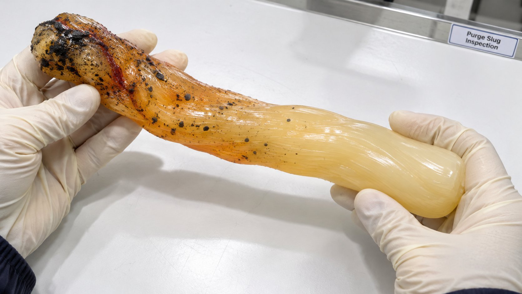
Troubleshooting Persistent Black Specks, Color Streaks, and Purging Failures
Your SOP is documented. Your operators are trained. Your compound matches the resin family. And yet the defects will not stop. Specks keep appearing twenty minutes into a run. Color streaks ghost back into parts long after the purge slugs looked clean. Or a hot-runner mold that ran perfectly last month suddenly produces contaminated parts from one specific gate.
These are the scenarios that make experienced processors question everything—and the ones where a systematic diagnostic approach saves hours of wasted purging. The instinct is always to escalate: more compound, higher temperature, another cycle. But escalation without diagnosis is just expensive guessing. The single most important rule in purging technology troubleshooting is deceptively simple:
Identify the contamination source before increasing purging intensity. Treating the wrong zone wastes compound, extends downtime, and leaves the actual problem untouched.
Every failure scenario below follows that principle—diagnose first, then act.
Persistent Black Specks and Carbonization That Will Not Clear
Black specks are the most common complaint in injection molding purging, and they are also the most misdiagnosed. Before running another purge cycle, you need to answer one question: where are the specks actually coming from?
That sounds obvious, but most operators skip the localization step entirely. They see specks in a molded part and immediately purge the barrel. If the real source is the hot-runner manifold, a worn check ring, or even mold surface contamination, barrel purging accomplishes nothing except burning through compound and production time.
Here is the diagnostic sequence that isolates the source:
- Retract the nozzle from the mold and perform a free-air purge. Inspect the extrudate carefully. If the free-air slugs are clean—no specks, no discoloration—the barrel and screw are not the problem. The contamination lives downstream in the nozzle tip, hot-runner manifold, or mold itself.
- If free-air slugs show specks, the barrel is the source. Increase barrel temperatures by 5-10 °C (10-20 °F) above normal processing setpoints. This softens carbonized deposits clinging to the screw flights and barrel wall, making them easier for the purging compound to dislodge. Plasticating specialists note that raising front-zone temperature and increasing backpressure during the purge cycle helps loosen degraded resin in the barrel and check-ring pockets.
- Switch from a mechanical compound to a chemical or hybrid formulation. If elevated temperatures and mechanical scrubbing do not clear the specks within two to three purge cycles, the carbon is likely baked onto surfaces in dead zones the mechanical compound cannot reach. A chemical purging liquid or hybrid with foaming action expands into those stagnant areas—behind the check ring, in the compression-to-metering transition, and along worn flight roots—and attacks degraded residue at the molecular level.
- Evaluate whether the carbon source is a permanent dead zone. If specks persist even after switching to a chemical compound and extending the soak time, the contamination is almost certainly being generated by worn hardware rather than simply residing on a cleanable surface. Contamination analysis from industry specialists confirms that worn screw and barrel assemblies, damaged check rings, and loose components create internal leaks where resin becomes trapped, isolated from normal flow, and eventually carbonizes—producing intermittent specks that return no matter how thoroughly you purge. At this stage, the solution is a screw pull and component inspection, not another purge cycle.
A useful mental model: think of black specks as existing in three tiers. Tier one is loose carbon floating in the melt stream—any decent purge removes it. Tier two is adhered carbon baked onto accessible barrel and screw surfaces—chemical or hybrid compounds remove it with correct technique. Tier three is carbon generated inside hardware dead zones created by wear—no compound removes it permanently because the source regenerates continuously.
Knowing which tier you are dealing with determines whether the answer is a better purge or a maintenance work order.
Color Streaking and Incomplete Color Changes After Purging
You ran the purge. The slugs looked clean. Production started, and the first dozen parts came out perfect. Then, ten or twenty shots later, a faint streak of the old color appears—and keeps appearing. What went wrong?
Color streaking after a seemingly successful purge almost always traces back to one of four root causes, and the fix is different for each:
- Insufficient purge volume. The compound displaced pigment from the main flow channel but did not generate enough total throughput to sweep secondary channels, flight roots, or the area behind the check ring. The remaining pigment slowly migrates back into the melt stream over subsequent shots. The fix: increase the number of short-shot purge cycles rather than running one long continuous purge. Short shots with brief hold pressure pack compound into dead spots more effectively than steady screw rotation alone.
- Wrong compound viscosity for the pigment type. Certain pigments—metallics, fluorescents, and highly loaded masterbatches—cling to metal surfaces with exceptional tenacity. A low-viscosity purge slides right over them. Color-change troubleshooting data shows that purge material must be more viscous than the outgoing resin to generate the shear forces needed to scrub pigment off flights and barrel walls. If your compound is not achieving that viscosity advantage at your processing temperature, switching to a higher-viscosity mechanical grade often resolves the streaking immediately.
- Inadequate screw-speed variation. Running the purge at a single constant RPM cleans one shear zone and leaves others untouched. Pigment trapped in the flight roots at low-shear positions never gets dislodged. Alternating between high and low RPM during the purge—creating changing shear profiles across the full flight surface—dramatically improves pigment displacement.
- Residual pigment trapped in check-ring gaps. A worn non-return valve that no longer seals properly allows contaminated melt to backflow into the screw channel during injection, instantly re-introducing old color into the new resin. If you notice that the screw recovers inconsistently or that backpressure fluctuates unpredictably during purging, the check ring is likely compromised. Temporarily increasing backpressure can partially compensate, but the real fix is inspection and replacement of the worn valve.
When color streaking persists after addressing all four factors, apply this escalation protocol:
- Increase purge volume by 25% and run additional short-shot cycles with 1-2 seconds of hold pressure per cycle.
- Switch to a higher-viscosity mechanical compound or a hybrid formulation.
- Raise barrel temperatures 5-10 °C above the outgoing resin's normal setpoint to keep residual pigment mobile and easier to displace.
- If the machine uses a hot-runner mold, move the investigation downstream—the barrel may already be clean while the manifold is still holding color (covered in the next subsection).
- If all purging adjustments fail, pull the screw and inspect the check ring, flight surfaces, and barrel bore for wear that creates permanent pigment traps.
Degraded Material Trapped in Hot-Runner Manifolds
Here is a pattern that frustrates even veteran injection molding purging teams: the barrel is verified clean through free-air purge shots, yet molded parts still show contamination—specks, streaks, or discoloration appearing from one or more gates. The barrel is not the problem. The hot runner is.
Standard barrel purging often fails to clear hot-runner contamination for a simple geometric reason. The manifold contains multiple branches, bends, nozzle drops, valve stems, and gate pockets—each one a potential dead zone where material stagnates and degrades. When the barrel purge pushes compound into the manifold, the compound takes the path of least resistance through the largest, warmest channels. Smaller branches, cooler nozzle tips, and stagnant pockets behind valve stems receive minimal flow and minimal cleaning force.
Manifold-specific purging demands a different technique than barrel cleaning. Hot-runner purging specialists recommend several targeted approaches:
- Zone-by-zone sequential purging. If color or contamination appears from specific gates, close off all other gates and inject high-velocity short shots through each affected drop individually. This concentrates the full injection pressure and compound volume through a single channel, generating far more cleaning force than spreading the same compound across all gates simultaneously.
- Balanced manifold temperatures before purging begins. Temperature imbalances as small as 10-20 °F between nozzle zones are enough to trap pigment in cooler areas. Color hides in the coldest sections of the manifold and releases later as streaks once production stabilizes. Verify that all zones are balanced before starting the purge—this single check eliminates a major source of "ghost" contamination that reappears mid-run.
- Valve-gate cycling during the purge. Open and close valve gates repeatedly while the purging compound is flowing. This sweeps compound behind valve stems and into seat pockets—areas that remain stagnant when gates are held in a fixed position.
- Steady, continuous flow rather than hesitation. Manifolds need constant melt velocity to displace trapped material. Pausing between shots or allowing long idle periods during the purge lets compound cool and stagnate in the same zones where the contamination lives. Keep cycles short and continuous.
- Chemical or foaming compounds for severe manifold contamination. When mechanical displacement alone cannot reach low-flow areas, a chemical compound that expands at processing temperature presses outward into dead spots that conventional flow never contacts. Follow with a brief mechanical or virgin-resin displacement purge to clear any residual chemical compound before production.
One additional consideration that often gets overlooked: avoid aggressive mold cooling during the purge. Cold steel increases pigment retention. Keep the mold at or near normal operating temperature so the compound flows freely through every channel.
Across all three failure scenarios—persistent black specks, returning color streaks, and manifold contamination—the diagnostic logic stays consistent. Localize the contamination source first. Match the corrective action to the specific zone and mechanism involved. And recognize the boundary between what purging can solve and what requires hardware intervention. That boundary is exactly where troubleshooting becomes strategy—connecting individual fixes into a holistic program that ties purging execution, hardware health, operator skill, and performance measurement into a single, trackable system.
Building a Complete Purging and Plasticizing Health Strategy
Individual fixes solve individual problems. A plant that troubleshoots one black-speck event, upgrades one compound grade, or retrains one operator will see a temporary improvement—and then drift right back to the same scrap rates within a few weeks. Lasting contamination control requires connecting every dimension covered in this guide—purging science, method selection, resin compatibility, hardware condition, preventive scheduling, and operator technique—into a single, coordinated system. Think of it less as a purging program and more as a plasticizing-system health program, where every plastic purge cycle is one data point in a much larger picture.
The Complete Purging Lifecycle from Prevention to Verification
Contamination management does not begin when the operator opens a bag of purging compound. It begins upstream, before resin ever enters the hopper, and it does not end until the results are documented and fed back into the next cycle. The lifecycle below captures every stage in sequence. When all seven steps operate consistently, changeover scrap drops, compound consumption stabilizes, and contamination events become the exception rather than the weekly norm.
- Upstream contamination prevention. Proper resin drying, sealed material handling, clean hopper loaders, and first-in-first-out inventory rotation eliminate contamination sources before they reach the barrel. Contamination prevention research confirms that material degradation, moisture absorption, and cross-contamination from poor storage are among the leading contributors to downstream defects—problems no purging compound should have to fix.
- Compound and method selection. Match the purging mechanism (mechanical, chemical, hybrid) to the contaminant type, and match the compound grade to both the outgoing and incoming resin families. Use the decision framework and resin-transition table from earlier sections as your selection tool—not habit, not whatever is left on the shelf.
- Purging execution with correct technique. Follow the documented SOP for the specific trigger type. Vary screw speed, maintain correct barrel temperatures, respect soak times for chemical compounds, and use the right sequence for the equipment involved—barrel first, then nozzle, then hot runner or die.
- Post-purge quality verification. Inspect purge slugs against defined cleanliness criteria before introducing production resin. For critical runs—automotive purging compounds applications, medical parts, optical components—verify the first production parts with a spectrometer check or magnified visual inspection. Never skip this step under schedule pressure.
- Documentation and trend tracking. Record the compound grade, quantity, number of cycles, changeover time, startup scrap, and any anomalies. This data is the early warning system that reveals hardware wear, procedural drift, and compound performance changes before they become visible defects.
- Periodic hardware audit. On a defined schedule—quarterly, semi-annually, or based on running hours—pull the screw and inspect flight edges, barrel bore, check ring, and end cap for wear indicators. Compare findings against previous audits to track degradation trends.
- Program review and SOP update. Use accumulated data to refine purge intervals, adjust compound quantities, update procedures for new resins, and recalibrate quality endpoints. A living program outperforms a static document every time.
Auto purging systems and automated compound dosing equipment can streamline steps two through five on high-volume lines, but the strategic framework remains the same whether the operator feeds compound by hand or a dosing system meters it automatically. The value lives in the consistency of execution, not in the sophistication of the delivery method.
Integrating Hardware Health into Your Purging Strategy
Every discussion about purging effectiveness eventually circles back to the same physical reality: the condition of the screw, barrel, check ring, and end cap sets a hard ceiling on how clean any purge cycle can get. A perfectly executed procedure with a perfectly matched compound still fails if the plasticizing components harbor dead zones created by wear.
The diagnostic indicators covered earlier—escalating compound consumption, persistent specks after multiple cycles, rising post-purge scrap rates, visible scoring on pulled screws, and metallic flecks in the purge stream—are not just troubleshooting signals. They are maintenance triggers. Integrating these checks into your periodic hardware audit turns them from reactive clues into proactive decision points.
When audit results confirm worn or mismatched plasticizing components, the path forward is replacement with hardware engineered for your specific machine, resin demands, and shot-size requirements. Generic replacements restore basic function but may not address the geometry or metallurgy issues that accelerated the original wear. NANHAIYA's custom injection molding screw barrels illustrate the tailored approach—their technical review evaluates screw geometry, wear patterns, melting and mixing performance, and material-retention concerns before manufacturing a replacement matched to the application. That specificity restores the tight flight-to-barrel clearance, correct compression ratio, and proper check-ring sealing that make every subsequent purge cycle effective again.
The relationship is symbiotic. Sound hardware makes purging compounds work as designed. Disciplined purging extends the life of sound hardware by preventing the abrasive carbon buildup that accelerates wear. Remove either half and the system degrades faster than it should.
Measuring Purging Program ROI
You cannot improve what you do not measure—a principle that applies to purging programs as directly as it applies to any other manufacturing process. Yet surprisingly few plants track purging performance with any rigor. They know they spend money on compounds and they know changeovers take time, but the connection between a structured program and bottom-line improvement stays anecdotal rather than quantified.
The framework below gives you a simple, practical template for measuring ROI. Compare baseline metrics captured before implementing a preventive purging program against the same metrics measured after the program has been running for a defined period—typically sixty to ninety days. Scrap-reduction methodology from purging specialists reinforces this approach: establish baseline data first, set measurable targets, then track results against those targets cycle by cycle.
| Metric | Baseline Measurement | Post-Program Measurement | Improvement (%) |
|---|---|---|---|
| Average changeover time (minutes) | ________ | ________ | ________ |
| Changeover scrap rate (parts or kg) | ________ | ________ | ________ |
| Purge-compound consumption per changeover (kg) | ________ | ________ | ________ |
| Startup reject count (parts to acceptable quality) | ________ | ________ | ________ |
| Unplanned downtime incidents per month (contamination-related) | ________ | ________ | ________ |
| Screw-pull frequency (per quarter) | ________ | ________ | ________ |
| Customer quality complaints (contamination-related) | ________ | ________ | ________ |
Fill in your own numbers and the story tells itself. Most plants that move from reactive to preventive purging see meaningful improvements across every row—often within the first quarter.
One dimension that deserves a line in any ROI conversation: environmental sustainability. Every kilogram of changeover scrap that does not get produced is a kilogram that does not go to landfill or consume energy in recycling. Every avoided screw pull reduces solvent use and waste disposal. Every shortened changeover lowers energy consumption per good part produced. These benefits align directly with lean manufacturing goals and with the broader sustainability commitments that customers in automotive, packaging, and consumer products increasingly require from their supply chains.
Purging plastic is not a single task. It is a system—one that spans chemistry, equipment, procedures, people, and measurement. The plants that treat it as a system stop chasing black specks. They prevent them.
Frequently Asked Questions About Purging Plastic
1. What is purging plastic and why is it important?
Purging plastic is the controlled process of displacing residual resin, colorant, degraded polymer, or additive buildup from a plastics processing machine's barrel, screw, check ring, nozzle, and melt-delivery components. It is performed before, during, or after production runs to restore a clean melt path. Effective purging matters because contamination from thermal degradation, pigment adhesion, and resin decomposition in dead spots leads to black specks, color streaks, and elevated scrap rates. Treating purging as a scheduled, process-critical operation rather than a reactive chore directly reduces changeover downtime, material waste, startup reject counts, and customer quality complaints across injection molding, extrusion, and blow molding operations.
2. What is the difference between mechanical, chemical, and hybrid purging compounds?
Mechanical purging compounds use a high-viscosity carrier resin that generates elevated shear stress as the screw rotates, physically scraping pigment and residue off barrel walls and flight surfaces. They work best for routine color changes and pigment removal but depend on direct melt contact, so they may underperform in dead zones. Chemical purging compounds contain reactive agents that break molecular bonds in degraded residue at processing temperature, often generating gas that expands into low-flow areas like check-ring pockets and hot-runner branches. Hybrid or foaming compounds combine both mechanical scrubbing and chemical reaction with controlled gas expansion, making them the most versatile option for severe contamination, flame-retardant residue, and complex tooling with multiple dead zones. Each type carries different cost, temperature sensitivity, and follow-up requirements.
3. How do you purge a hot-runner injection mold effectively?
Hot-runner purging requires a sequential approach that goes beyond standard barrel cleaning. Start by purging the barrel with the nozzle retracted from the mold, then perform free-air purge shots through the nozzle to clear the nozzle bore. Next, reconnect to the mold and inject the purging compound into the hot runner using short, high-velocity shots to create turbulence inside the manifold. For gates showing persistent contamination, close off all other gates and concentrate purging force through each affected drop individually. Cycle valve gates open and closed during the purge to sweep compound behind valve stems. Verify that all manifold zone temperatures are balanced before starting, since even small temperature imbalances trap pigment in cooler sections. Use a compound rated for hot-runner use to avoid plugging narrow gate restrictions.
4. Why do black specks keep coming back after purging?
Persistent black specks that return shortly after purging typically originate from one of three sources. First, carbon deposits may be lodged in dead zones that standard mechanical compounds cannot reach, requiring a switch to a chemical or hybrid formulation with foaming action. Second, the contamination source may not be in the barrel at all but rather in the hot-runner manifold, nozzle tip, or mold—so a free-air purge test should be performed to isolate the source. Third, and most commonly overlooked, worn plasticizing hardware such as eroded screw flights, scored barrel bores, or damaged check rings creates permanent stagnant pockets where resin degrades continuously and regenerates carbon between purge cycles. When specks persist after multiple correctly executed purge cycles with the right compound, the root cause is almost always hardware wear that requires component inspection and replacement rather than additional purging.
5. How often should you purge a plastics processing machine?
Purge frequency depends on several variables specific to your operation, including the resin type, processing temperature, run length, and historical contamination data. Common triggers that should initiate a purge include every material or color change, every planned shutdown exceeding four hours, every startup after an unplanned stoppage, and a fixed calendar interval for machines running continuous production without changeovers. Proactive preventive purging at defined intervals removes thin, freshly formed deposits that are far easier to displace than baked-on carbonization, ultimately reducing total compound consumption over time. The best practice is to establish a documented SOP with specific triggers, compound grades, quantities, temperature settings, and measurable cleanliness endpoints for each scenario, then refine intervals based on logged results over sixty to ninety days.
Written by
Nanhaiya Technical Team
Zhoushan Nanhaiya Plastic Machinery Co., Ltd.
The Nanhaiya technical team supports screw and barrel manufacturing projects through application review, technical communication, custom manufacturing coordination, and production and quality control.
Discuss Your Application
Related Articles
More insights on screw barrel technology and plastics processing.
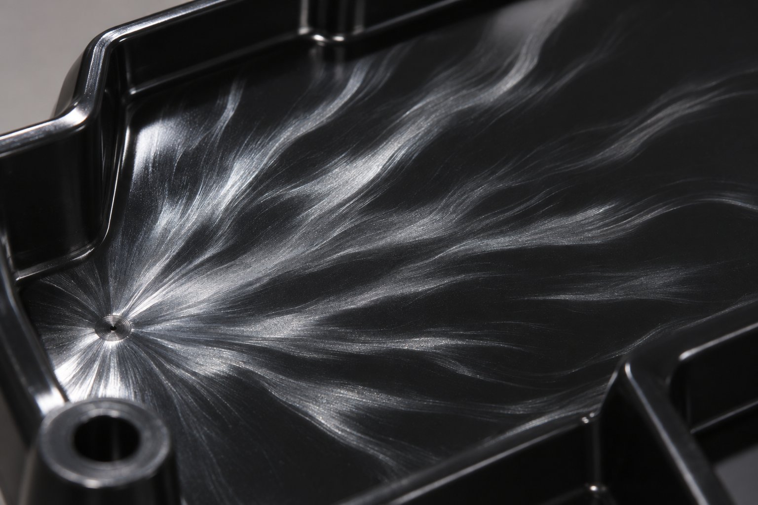
Stop Chasing Symptoms: Fix Injection Molding Splay at the Source
Nov 6, 2026
Learn what causes injection molding splay, how to diagnose moisture, shear, and degradation splay by location, and fix silver streaks at the root cause.
Read Article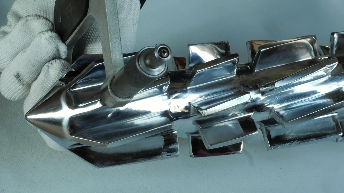
Purging Compound Decoded: Barrel Chemistry To Bottom-Line Savings
Nov 5, 2026
Learn how purging compounds clean barrels, screws, and hot runners. Compare chemical vs mechanical types, step-by-step procedures, selection tips, and cost savings.
Read Article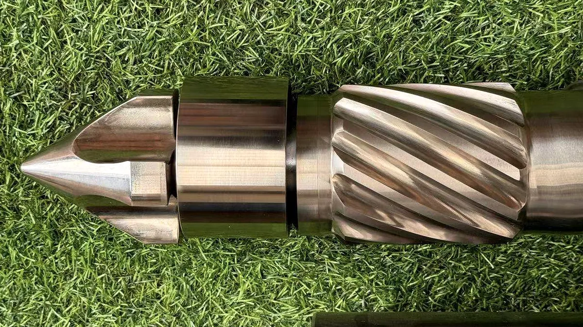
Stop Wasting Resin: How Mechanical Purging Compound Actually Works
Nov 5, 2026
Learn how mechanical purging compounds use shear force, high viscosity, and abrasive fillers to clean barrels. Covers dosage, procedures, resin matching, and maintenance tips.
Read ArticleLooking for something else?
Search by material, symptom or product and jump straight to the relevant page.
These are navigation suggestions based on keyword matching — not a quotation, not a delivery commitment, and not a substitute for engineering review. Final specification is confirmed by our engineers against your drawings and processed material.
Need help with screw barrel selection?
Share your machine model, processed material and application. Our team can help with pricing and technical support.