

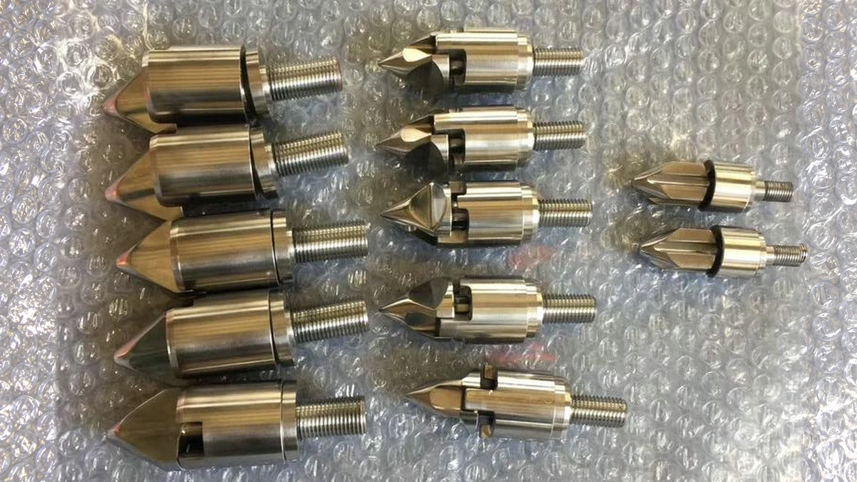
What the Screw Tip Does and Why It Matters
Imagine a component smaller than your fist quietly controlling the consistency of every single part your injection molding machine produces. That component is the injection molding screw tip — the pointed or radiused piece that threads onto the front end of the reciprocating screw and seats inside the check ring (non-return valve) assembly. Despite its modest size, it acts as the gatekeeper between molten plastic ready for injection and the feed section behind it. When it works correctly, you barely notice it. When it doesn't, defects pile up fast.
What Is an Injection Molding Screw Tip
The screw tip is the forward-most component of the plasticizing assembly. It threads directly onto the screw's nose, and together with the check ring and rear seat, it forms what's known as the injection molding screw tip assembly. This three-piece assembly functions as a non-return valve — the mechanical barrier that prevents molten resin from flowing backward during the injection and hold phases of each cycle.
During screw recovery, molten plastic flows forward around the tip and accumulates in front of it. The moment injection begins, the check ring slides rearward and seats against the retainer, sealing the melt path so hydraulic or electric pressure can push the entire shot into the mold. This seal must be tight and repeatable — every single cycle.
The screw tip assembly is the only mechanical seal between the melt cushion and the feed section, making it the single most critical wear point for shot-to-shot consistency.
That distinction matters more than most processors realize. A worn or poorly matched assembly allows melt to leak backward during injection and pack-hold. Even minor backflow introduces variation in cushion position, effective shot volume, and packing pressure — the very metrics that determine whether parts meet specification or end up in the scrap bin.
Why This Component Deserves Dedicated Attention
Here's a scenario you'll recognize if you've spent any time on the production floor: a machine arrives — purchased used or inherited from a different product line — and the screw tip assembly inside it is whatever the previous owner or OEM selected for general-purpose use. Nobody questions it. The machine runs, parts come out, and the tip becomes invisible until something goes wrong.
The problem? Tip geometry, material of construction, and physical condition directly affect cushion stability, recovery time, and defect rates. A tip designed for commodity resins won't hold up against glass-filled nylon. A worn check ring that's lost a few thousandths of an inch on its outer diameter can silently bleed melt backward, causing the kind of gradual cushion drift and part-weight variation that drives process engineers to chase phantom issues elsewhere in the system.
Yet most available resources on injection molding screw tips cover only a narrow slice of the subject — a product listing here, a brief mention in a troubleshooting guide there. What's missing is a single, practical technical reference that follows the real workflow of process engineers and maintenance technicians: understanding how the assembly functions cycle by cycle, selecting the right design and material for the application, installing it correctly, and recognizing when wear has crossed the line from acceptable to costly.
That's exactly what this article delivers. Each section ahead maps to a specific decision or task you'll face when working with injection molding screw tip assemblies — from the physics of melt flow around the tip, through design tradeoffs between different valve styles, all the way to diagnosing the production-floor symptoms that signal it's time for a replacement. The goal is straightforward: give you the depth and clarity to make better decisions about the small component with outsized influence on everything your machine produces.
How the Screw Tip Assembly Functions in Each Cycle Phase
Every injection molding cycle asks the screw tip assembly to do two opposing jobs in rapid succession: first, let molten plastic flow freely past it, and then, fractions of a second later, slam shut and hold back pressures that can exceed 20,000 psi. Understanding exactly how this transition happens — and where it can go wrong — is essential for anyone troubleshooting cushion variation, short shots, or inconsistent part weight. Let's walk through the mechanism phase by phase.
Screw Tip Behavior During Plasticating Recovery
During recovery, the screw rotates and conveys resin forward through the metering section. As melt pressure builds ahead of the screw tip, that pressure pushes the check ring forward along the tip body, opening annular flow channels between the ring's inner bore and the tip's outer surface. Molten resin flows through these channels and accumulates in the space between the tip and the nozzle, building the shot.
Think of it like a one-way turnstile — during this phase, the gate is wide open and traffic moves in only one direction. The back pressure set on the machine determines how much resistance the melt encounters as it passes through, and that resistance directly influences melt uniformity and recovery time.
Here's where tip geometry starts to matter. The taper angle of the screw tip, the number and width of flow channels, and the overall length of the flow path all affect three critical variables:
- Pressure drop — A steep taper angle or narrow channels force the melt through a tighter restriction, increasing pressure loss and requiring higher back pressure to maintain shot size.
- Shear rate — Narrower passages raise shear on the melt, which can help with mixing but risks overheating shear-sensitive resins like PVC or POM.
- Dead spots — Any stagnant zone where resin can hang up becomes a degradation site. Over time, trapped material carbonizes and flushes into the melt stream as black specks or contamination.
A well-designed screw tip injection molding assembly balances these tradeoffs: it provides enough open flow area to minimize pressure drop and dead spots while still maintaining the structural geometry needed for a reliable seal when the valve closes.
Sealing Function During Injection and Hold
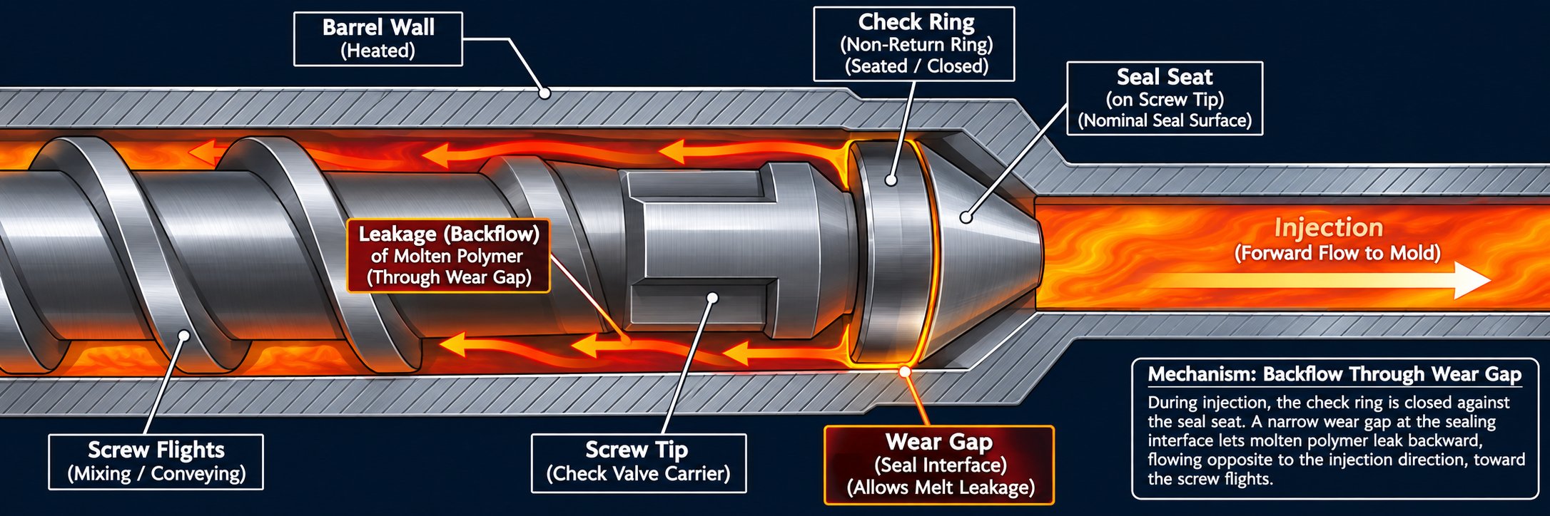
The moment injection begins, everything reverses. Hydraulic or electric drive pushes the screw forward, and the sudden forward acceleration of the melt in front of the tip creates a pressure differential that forces the check ring rearward. The ring slides back along the tip body until its angled sealing surface contacts the rear seat (retainer), closing the valve. Two seals form simultaneously: one between the ring and the rear seat, and another between the ring's outer diameter and the barrel bore.
The quality of these seals determines how much melt leaks backward past the assembly during injection and pack-hold — a phenomenon engineers call "leakage flow." Even seemingly insignificant backflow has measurable consequences. As injection molding process experts emphasize, how well the check ring functions to prevent backflow determines the consistency of shot size and cushion position.
Consider what happens when leakage flow increases by even a small amount. Some portion of the melt that was supposed to fill and pack the cavity instead slips backward over the screw flights. The effective shot volume drops, packing pressure falls off, and the cushion position at the end of hold drifts forward. On a part-by-part basis, you'll notice rising variation in part weight, fill patterns, and dimensional accuracy — exactly the kind of creeping inconsistency that's difficult to pin down without pulling the screw for inspection.
Velocity also plays a role in how well the ring seats. At high injection speeds, the ring snaps rearward quickly and seats with greater force, producing a tighter seal. At lower velocities, the separating force created by resin leaking upstream can resist complete closure, causing erratic cushion behavior or, in worst cases, partial non-closure of the valve. This is why injection molding machine screw tips that perform perfectly on fast-cycling packaging molds may show cushion instability when moved to a slower, thick-walled application.
The Three-Phase Cycle at a Glance
To tie it all together, the complete operating sequence of the screw tip assembly breaks down into three distinct phases:
- Recovery — The screw rotates, the check ring slides forward, annular flow channels open, and molten resin passes around the tip to build the shot ahead of the screw.
- Injection — The screw drives forward, the check ring seats rearward against the retainer, flow channels close, and the melt is sealed for delivery into the mold cavity.
- Hold (Pack) — The ring remains seated, maintaining pack pressure on the cavity to compensate for volumetric shrinkage as the part cools and solidifies.
Each transition between phases demands precision. A ring that's slow to open restricts melt flow and extends recovery time. A ring that's slow to close lets melt bleed backward during the critical first moments of injection, robbing the cavity of volume. And a ring that can't maintain its seal through the entire hold phase allows cushion drift that compounds with every shot.
This cycle-by-cycle mechanical reality is exactly why the design of the tip assembly — its geometry, sealing surfaces, and material of construction — has such a direct impact on the defects and process instabilities that injection molding press screw tips are often the last place people look. The next logical question, then, is which tip design best handles these competing demands for your specific application.
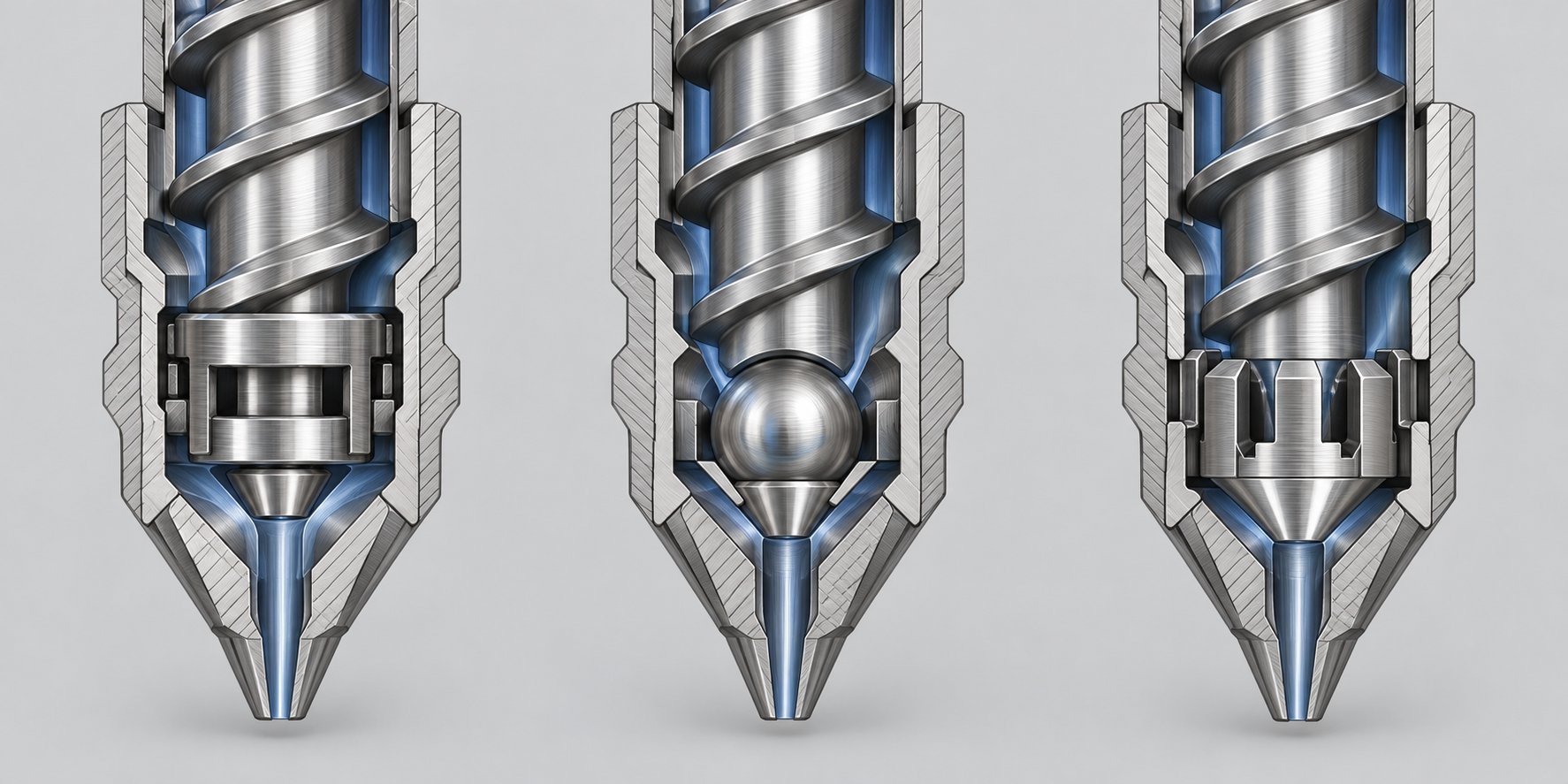
Common Screw Tip Types and Their Design Tradeoffs
Not every non-return valve handles those competing demands — fast, clean flow during recovery and an airtight seal during injection — in the same way. The injection molding screw tip design you choose determines which tradeoff you're making: sealing speed versus pressure drop, ease of cleaning versus shot-to-shot precision, upfront cost versus long-term barrel health. Understanding the why behind each design family puts you in a much stronger position than simply defaulting to whatever the OEM shipped with your machine.
Broadly, tip designs fall into a few major categories: sliding check ring, ball check and poppet, and locking ring or controlled-closure configurations. Each has a distinct mechanical philosophy, and each excels — or struggles — in specific processing environments.
Sliding Ring Check Valve Assemblies
The sliding check ring is the workhorse of the injection molding industry, and for good reason. In its most common form, it's a three-piece assembly: a retainer (the tip body that threads onto the screw nose), a check ring that slides freely along it, and a rear seat against which the ring seals during injection. Some manufacturers also offer a four-piece variant where the front seat is a separate component made from a harder, more wear-resistant material than the retainer itself.
During recovery, the ring slides forward, opening annular channels for melt to pass around the tip. During injection, it reverses direction and mates against the rear seat. Critically, the ring does not rotate with the screw — it only moves axially, forward and backward. This distinction has significant implications for barrel life, which we'll revisit in a moment.
Pros
- Simplicity and low cost — Fewer components and straightforward geometry make sliding ring assemblies the most affordable option to purchase, stock, and replace.
- Ease of cleaning — The open annular flow path has fewer dead spots than enclosed ball or poppet housings, which speeds up color and material changes.
- Barrel-friendly operation — Because the ring doesn't rotate, it produces significantly less abrasive contact with the barrel bore, extending barrel service life.
- Versatility — Suitable for most commodity resins (PP, PE, PS, ABS) and many engineering resins, making it the default starting point for the majority of applications.
Cons
- Slower ring closure — The ring relies entirely on injection-phase melt pressure to push it rearward and seat it. At very high injection speeds or with low-viscosity resins, there can be a brief lag in closure that allows more backflow variation compared to mechanically actuated designs.
- Wear-driven leakage — As the check ring's outer diameter erodes over time, the annular gap between the ring and the barrel bore widens. This progressively increases leakage past the OD seal, degrading cushion consistency long before the ring-to-seat seal shows visible damage.
- Front seat wear at high RPM — Excessive screw recovery speeds can cause the ring to repeatedly slam against the front seat, carving a notch that increases ring travel distance and delays closure.
Despite these limitations, industry specialists consistently recommend sliding check ring assemblies as the most versatile and durable option with the fewest drawbacks across general processing conditions. The four-piece variant, in particular, addresses front seat durability by allowing a harder material insert that outlasts a one-piece retainer — and provides an easier recovery path if a stud ever breaks in the screw nose.
Ball Check and Poppet Style Tips
Imagine replacing the sliding ring entirely with a single ball or a tapered poppet that sits inside a housing bored into the tip body. During recovery, melt pressure lifts the ball or poppet off its seat, opening the flow path. During injection, the ball drops back (or is spring-loaded back) into its seat, plugging the flow hole and sealing the assembly.
This approach changes the sealing dynamic in meaningful ways. Because the ball or poppet contacts a small, precisely machined seat rather than a wide annular surface, the closure event can be faster and more positive — especially with low-viscosity resins or very small shot sizes where a sliding ring might not generate enough differential pressure to seat reliably. Mechanically actuated poppet designs using embedded springs take this further, forcing instantaneous shutoff independent of screw motion to minimize part-weight deviations.
The tradeoffs, however, are real:
- Higher pressure drop — The melt must flow through a more restrictive internal geometry, which increases pressure loss during recovery and can extend cycle times on larger shot sizes.
- Greater dead-spot risk — The internal housing that cradles the ball or poppet creates pockets where resin can stagnate, degrade, and eventually flush downstream as black specks or carbonized particles. This makes ball check designs less forgiving with heat-sensitive materials despite their simplified geometry being sometimes marketed as better for sensitive resins.
- Difficult color and material changes — Those same internal recesses trap pigment and prior-run material, requiring longer purge cycles to achieve a clean changeover.
- Barrel wear from rotation — In most ball check and poppet configurations, the sealing OD of the housing rotates with the screw. This constant rotational contact against the barrel bore accelerates barrel ID wear, a concern that experienced screw and barrel suppliers flag repeatedly.
Ball checks and poppets earn their place in specific niches — very small shot sizes, ultra-low-viscosity resins, or applications where shutoff consistency matters more than anything else. For general-purpose molding, though, their drawbacks usually outweigh the sealing advantage.
Locking Ring and Controlled-Closure Designs
Locking ring tips — sometimes called castle tips because of their keyed or tabbed geometry — are a variant of the check ring concept. Instead of floating freely, the ring keys into slots on the retainer, which means it rotates with the screw during recovery rather than staying stationary. Popular with several Japanese OEMs, the locking ring gained a reputation for producing a tighter seal because the keyed engagement eliminates some of the random positioning variability of a free-floating ring.
But that reputation deserves scrutiny. As injection molding process specialist John Bozzelli has documented, a locking ring that has been in service for roughly 2,000 hours can show dramatic scoring and scratching — both circumferentially from rotation and horizontally from axial travel. Because the ring rotates against the barrel bore, it introduces the same accelerated barrel wear issue seen with ball check and poppet designs. The cost of a barrel replacement dwarfs the price of any tip assembly, making this a tradeoff that deserves careful accounting.
Beyond locking rings, a separate category of premium controlled-closure designs uses mechanical features — pins, deceleration ramps, or spring-loaded elements — to reduce the variability in exactly when and how the ring seats during injection. These injection molding screw tip assemblies are engineered to close at the same point in the injection stroke every cycle, regardless of melt viscosity or injection speed fluctuations. The payoff is tighter shot-to-shot repeatability, which matters most in applications like:
- Tight-tolerance medical components where part-weight deviation must stay within fractions of a percent
- Optical parts where packing consistency directly affects surface finish and dimensional accuracy
- Micro-molding applications where even tiny absolute backflow volumes represent a large percentage of the total shot
The cost premium is significant — both for the components themselves and for the maintenance complexity of multi-piece assemblies with springs and precision-fit parts. For high-value, low-tolerance production, that premium pays for itself. For general commercial work, a well-maintained sliding ring will deliver comparable results at a fraction of the investment.
Comparing Injection Molding Screw Tip Design Options
Choosing between these design families becomes much easier when you line up the criteria that actually matter on the production floor. The table below maps each tip type against the performance dimensions that drive real-world selection decisions:
| Criteria | Sliding Ring (Free-Flow) | Ball Check / Poppet | Locking Ring (Castle) | Controlled-Closure / Premium |
|---|---|---|---|---|
| Sealing Speed | Moderate — dependent on melt pressure differential | Fast — positive shutoff, especially with spring assist | Moderate — similar to sliding ring but with rotational dynamics | Very fast — mechanically timed closure, independent of melt pressure |
| Pressure Drop | Low — open annular flow path | Higher — restrictive internal geometry | Low to moderate — similar flow area to sliding ring | Varies by design — optimized for specific applications |
| Dead-Spot Risk | Low — streamlined flow channels | Higher — internal housing traps resin | Low to moderate — keyed features can create minor hang-up zones | Low — precision-engineered internal geometry |
| Ease of Color Change | Good — minimal internal recesses | Poor — internal pockets retain pigment | Good — similar to sliding ring | Moderate — more components to purge through |
| Barrel Wear Impact | Minimal — ring does not rotate | Higher — sealing OD rotates with screw | Higher — ring rotates with screw, documented scoring after ~2,000 hr | Varies — depends on whether sealing OD is fixed or rotating |
| Relative Cost | Low | Moderate | Moderate | High |
| Best-Fit Applications | General-purpose commodity and engineering resins; frequent changeovers | Small shot sizes; low-viscosity resins; specialized shutoff-critical work | OEM-specified machines (common in Japanese presses) | Tight-tolerance medical, optical, and micro-molding applications |
Notice a pattern? The sliding ring occupies the broadest sweet spot — acceptable performance across nearly every criterion, with no single catastrophic weakness. Ball checks and poppets solve specific sealing challenges but introduce penalties elsewhere. Locking rings offer marginal sealing improvements that may come at the expense of barrel longevity. And controlled-closure designs deliver the ultimate in repeatability for those applications where nothing less will do.
Selecting the right design family is only half the equation, though. Even the best-engineered tip geometry will fail prematurely if it's built from the wrong material for the resin being processed. A sliding ring running glass-filled nylon, for instance, faces abrasive wear rates that can erase its sealing surfaces in a fraction of the time it would last on unfilled polypropylene — which raises a critical question about what these components should actually be made of.
Screw Tip Materials of Construction and Resin Compatibility
A perfectly designed valve geometry means nothing if the metal it's made from can't survive the resin flowing through it. Glass fibers will sandblast a soft steel seat flat in weeks. Corrosive off-gases from PVC will pit and crater an unprotected tool steel surface until the seal barely functions. Yet material selection for injection molding screw tip components is one of the most overlooked decisions in the entire plasticizing assembly — often defaulted to whatever the OEM shipped or whatever is cheapest on the quote sheet.
The consequences show up slowly, then all at once. A tip that wears prematurely compromises seal quality cycle by cycle, gradually widening leakage paths until cushion variation, short shots, and part-weight drift force an unplanned production stop. Understanding which construction materials match which resin families is the most direct way to prevent that scenario.
Tool Steel and Nitride-Hardened Components
Standard tool steels form the baseline for most injection molding screw tip assemblies, and for good reason — they offer a strong combination of toughness, machinability, and cost-effectiveness when processing non-abrasive, non-corrosive resins. You'll encounter several common grades in this category:
- D-2 tool steel — A high-carbon, high-chromium grade valued for its excellent abrasion resistance and dimensional stability after heat treatment. It performs well in moderate-wear applications but lacks the corrosion resistance needed for chemically aggressive melts.
- H-13 tool steel — A hot-work steel designed to maintain hardness at elevated temperatures. Its toughness and resistance to thermal fatigue make it a popular choice for tip bodies and retainers exposed to repeated heating and cooling cycles.
- CPM grades (e.g., CPM 9V, CPM 10V) — Particle metallurgy steels with a uniform carbide distribution that delivers superior wear resistance compared to conventionally melted tool steels. Hardened tool steels like CPM 9V are specifically recommended for applications where abrasive wear demands more than standard alloys can provide.
For shops running unfilled commodity resins — polypropylene, polystyrene, ABS, polyethylene — a properly hardened tool steel tip assembly will deliver excellent service life at moderate cost. Surface treatments like nitriding push performance further by diffusing nitrogen into the steel's surface layer, creating a hard case (typically 60-70 HRC) that resists adhesive and mild abrasive wear without altering core toughness. Through-hardening achieves similar surface hardness across the full cross-section, making it preferable for components subjected to high compressive seating forces during injection.
The key limitation? Standard tool steels have a high iron matrix, which makes them vulnerable to chemical attack from corrosive melt byproducts. And while nitriding and hardening improve surface wear resistance, they don't add enough protection to survive heavily glass-filled or mineral-filled compounds over extended production runs. When those resins enter the picture, you need to step up to a different class of materials entirely.
Stainless Steel, Bimetallic, and Coated Options for Demanding Resins
Imagine processing PVC for thousands of hours. As the resin melts and flows through the screw tip assembly, hydrochloric acid off-gases quietly attack every iron-rich surface they contact. The same corrosive mechanism applies to acetals (which release formaldehyde), fluoropolymers like PTFE and FEP, and certain flame-retardant additives. As industry experts at Glycon Corp. explain, corrosion gradually destroys the metal surface, making it vulnerable to accelerated mechanical wear — a compounding failure mode where chemical and physical degradation reinforce each other.
For these corrosive environments, stainless steel or nickel-based alloy tip components replace the standard tool steel construction. Grades with high nickel and chromium content resist the chemical attack that would quickly degrade a D-2 or H-13 surface. The tradeoff is that many corrosion-resistant alloys are softer than hardened tool steels, so they may wear faster from purely mechanical abrasion. Selecting the right alloy means balancing corrosion resistance against the physical demands of the specific application.
Abrasive resins present the opposite challenge. Glass-filled nylon, mineral-filled polypropylene, and ceramic-loaded compounds don't corrode metal — they erode it. Every fiber or particle dragged across the check ring seat, the tip taper, and the ring OD acts like fine sandpaper, steadily grinding away the sealing surfaces that keep melt from leaking backward. Some of the most aggressive fillers can reduce useful component life by 50% or more compared to unfilled resins.
For these applications, bimetallic constructions and carbide-lined inserts offer the durability that solid tool steels simply can't match. Bimetallic tip components feature a wear-resistant alloy liner — often tungsten carbide or a nickel-tungsten composite — metallurgically bonded to a tougher steel substrate. The hard liner handles the abrasion while the substrate absorbs impact and thermal stress. Carbide inserts at critical sealing surfaces accomplish the same goal in a more targeted way, protecting only the high-wear zones.
Between the extremes of standard tool steel and full bimetallic construction, coatings offer a practical middle ground. Chrome plating, nickel-boron, and PVD (physical vapor deposition) treatments add a thin but hard protective layer to existing steel components. These coatings are particularly useful for operations running a mix of resin types — some mildly abrasive, some moderately corrosive — where full bimetallic construction would be overkill but unprotected tool steel would wear too quickly.
Matching Resin Characteristics to Tip Material
The decision tree for injection molding screw tip material selection really comes down to one question: what is the resin doing to the metal? Here's a practical summary of the most common pairings:
- Unfilled commodity resins (PP, PE, PS, ABS) → Standard tool steel (D-2, H-13) with nitriding or through-hardening. Cost-effective, durable, and widely available from OEM injection molding screw tip assemblies and aftermarket suppliers alike.
- Corrosive resins (PVC, acetal, fluoropolymers, flame-retardant compounds) → Stainless steel or nickel-based alloys. Prioritize chemical resistance over maximum hardness.
- Glass-filled, mineral-filled, or ceramic-loaded resins → Bimetallic constructions or carbide inserts at sealing surfaces. A screw tip for glass filled resin must withstand continuous abrasive contact without losing the dimensional precision that keeps the check ring sealing properly.
- High-volume production with mixed or rotating resin families → Coated tool steel (chrome, nickel-boron, or PVD) as a versatile option that handles moderate abrasion and mild corrosion without the cost of full bimetallic construction.
Choosing the wrong material of construction is one of the most common — and most expensive — mistakes in screw tip selection. The failure mode is deceptive: the tip doesn't break catastrophically. Instead, it wears gradually, widening seal clearances a few tenths of a thousandth at a time until one day the process window that used to be comfortable is suddenly razor-thin. By the time a process engineer recognizes the pattern, the production floor has already absorbed weeks or months of elevated scrap, inconsistent part weights, and the hidden cost of operators chasing settings to compensate for a seal that no longer holds.
Material compatibility, then, isn't just a line item on a purchase order — it's a direct predictor of how long your screw tip assembly will maintain the sealing performance your process depends on. And that material decision doesn't exist in isolation. It works in tandem with the tip's design type, the part-quality requirements of the application, and the dimensional fit to the specific machine — all of which factor into a structured selection process.
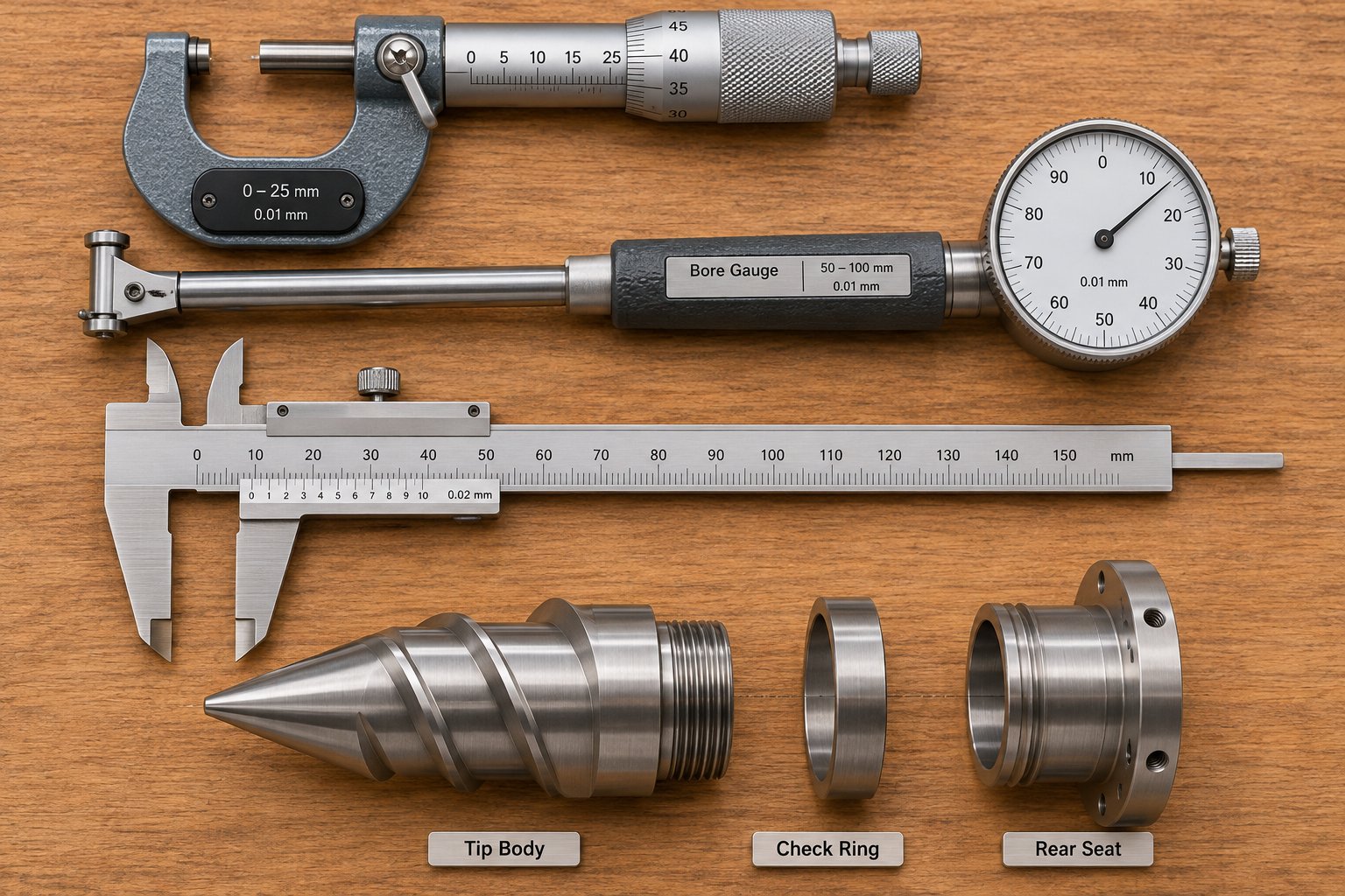
How to Select the Right Screw Tip Assembly
You know the design families. You understand the material options. But how do you actually narrow those choices down to the one assembly that belongs in your machine? Too often, this decision gets made by default — someone orders the same part number that was on the last purchase order, or grabs whatever is sitting on the maintenance shelf. That approach works until it doesn't, and when it fails, the cost shows up as cushion instability, elevated scrap rates, or premature wear that forces another unplanned replacement far too soon.
A structured injection molding screw tip selection guide doesn't have to be complicated. It follows a logical sequence: start with the resin, then layer in part-quality demands, factor in production realities, and finally verify that everything fits the machine. Each step eliminates options until you're left with a short list that actually makes engineering sense.
Matching Tip Style to Resin and Application Requirements
The resin family is always the first filter. Ask yourself three questions about the material you're processing:
- Is it abrasive? Glass-filled, mineral-filled, or ceramic-loaded compounds demand wear-resistant materials — bimetallic construction or carbide inserts — and favor sliding ring designs whose non-rotating check ring minimizes barrel bore erosion.
- Is it corrosive? PVC, acetal, fluoropolymers, and heavily flame-retarded resins require stainless steel or nickel alloy components. Tip geometry should also minimize dead spots where corrosive off-gases concentrate and attack metal surfaces.
- Is it heat-sensitive or low-viscosity? Materials that degrade quickly at elevated temperatures — or that flow so easily they slip past conventional seals — may benefit from ball check or controlled-closure designs offering faster, more positive shutoff.
If the resin is a standard, unfilled commodity polymer like PP, PE, or ABS, a sliding ring assembly in hardened tool steel covers your needs at the lowest cost and broadest versatility. That's the default starting point, and you only move away from it when the resin demands otherwise.
Part-quality requirements form the second filter. A general commercial-tolerance consumer product doesn't need the same shot-to-shot repeatability as a tight-tolerance medical connector or an optical lens. For applications where part-weight variation must stay within fractions of a percent, controlled-closure or premium locking designs justify their higher cost by reducing ring-closure variability to near zero. For everything else, a well-maintained sliding ring delivers more than adequate consistency.
Production priorities add the final practical layer. Frequent color changes and short runs favor sliding ring assemblies with open flow paths and minimal internal recesses — they purge faster and get you back into production sooner. Dedicated long runs on a single resin open the door to ball check or poppet designs if shutoff performance is the priority, since the downside of slow color changes becomes irrelevant. High-volume operations running rotating resin families benefit from coated tool steel tips that handle moderate abrasion and mild corrosion without requiring a dedicated assembly for each material.
Walk through these three filters in order — resin, quality requirements, production priorities — and you'll arrive at a clear answer for how to select an injection molding screw tip that's genuinely matched to your process rather than inherited by accident.
Dimensional Fit and Machine Compatibility Considerations
Here's where even a perfect design-and-material decision falls apart if the details are wrong. Every screw tip assembly must physically mate with the screw, barrel, and OEM specifications of the machine it's going into. A tip designed for a 40 mm screw won't thread onto a 45 mm nose. A check ring ground to the wrong OD will either jam in the barrel or leave a gap wide enough to bleed melt backward on every shot.
Before ordering any replacement or aftermarket assembly, verify these critical specification checkpoints:
- Screw diameter — The nominal bore size that defines the entire plasticizing system and determines the scale of all mating components.
- Thread type and pitch — Screw nose threads vary by OEM and machine model. Metric, unified, and proprietary thread forms all exist in the field, and a mismatch means the tip either won't install or won't seat properly.
- Tip overall length — An assembly that's too long can bottom out and prevent proper nozzle seating; one that's too short may leave excessive dead volume ahead of the screw.
- Check ring outer diameter and barrel bore clearance — This is the specification that most directly controls leakage past the OD seal. Wear to the check ring OD from processing abrasive resins results in excessive clearance with the barrel wall, inhibiting a strong cushion. A new ring must be sized to the actual barrel bore — not the nominal bore — especially on machines with worn barrels.
- Rear seat angle and diameter — The contact geometry between the check ring and retainer seat determines how cleanly and completely the valve closes. Mismatched angles produce a line contact instead of a full-face seal, allowing melt to wash past and erode the surfaces even faster.
Dimensional mismatch — even a few thousandths of an inch on the ring OD — can introduce excessive backflow that undermines shot consistency regardless of how well the tip was designed or what premium alloy it's made from. This is why screw tip assembly machine compatibility isn't just a procurement detail; it's a process-critical specification that directly affects part quality.
Aftermarket and replacement tips must meet or exceed OEM dimensional tolerances to maintain proper seal function. Reputable suppliers will ask for your machine make, model, screw diameter, and existing assembly dimensions before confirming compatibility — and that verification step is worth insisting on, even if it adds a day to the quoting cycle. The alternative is installing a tip that looks right, threads on without complaint, and quietly leaks just enough melt backward to keep your process engineers chasing phantom problems for weeks.
With the right design, material, and dimensional fit locked in, the next variable that separates a reliable assembly from a premature failure is how it gets installed — a step where seemingly small procedural details like torque values and anti-seize practices carry surprisingly high consequences.
Installation and Torque Best Practices for Screw Tip Assemblies
You've selected the right design, matched the material to your resin, and verified every critical dimension. The assembly arrives, it threads onto the screw nose — and this is exactly where a surprising number of processors undermine everything they just got right. A screw tip installed at room temperature, torqued without anti-seize, or tightened to the wrong specification can gall its threads on the first heat cycle, loosen mid-production, or crack under injection pressure. The installation procedure itself is a make-or-break step, yet it's one of the least documented aspects of injection molding screw tip maintenance.
Getting it right isn't complicated. It does, however, require following a specific sequence — and resisting a few shortcuts that seem harmless but carry real consequences.
Proper Removal and Inspection Before Installation
Before a new assembly goes on, the old one has to come off — and how you remove it matters just as much as how you install the replacement. The correct procedure starts well before anyone picks up a wrench:
- Heat the barrel to processing temperature. The screw tip was tightened at elevated temperature, and thermal expansion locked the threads into place. Attempting removal on a cold barrel risks galling the threads, stripping them, or snapping the tip body entirely. Let the barrel soak at its normal setpoint until temperatures have fully stabilized.
- Purge residual resin. Run a heat-stable, unfilled purge compound or general-purpose resin like natural polypropylene through the system. As Services for Plastics advises, never attempt to rotate or retract a screw without resin present — doing so risks scoring the barrel bore and damaging flight lands.
- Retract and remove the screw. Pull the screw from the barrel following your machine's standard screw-pull procedure. With the screw accessible, use the correct wrench or fixture to unthread the tip while the assembly is still hot. Pipe wrenches, vise grips, and improvised tools invite rounded flats, cracked bodies, and hand injuries. Purpose-built screw tip wrenches matched to the hex or spanner configuration of the specific assembly are the only appropriate option.
- Inspect before installing anything new. With the old tip removed, examine the screw nose threads for signs of galling, cross-threading, or material buildup. Check the thread root for cracks or deformation. Inspect the seat surface on the screw nose — the register where the retainer mates — for washout, scoring, or uneven wear. A new tip assembly threaded onto a damaged screw nose will never seal properly, no matter how precisely it was manufactured.
Don't skip the barrel bore, either. While the screw is out, visually inspect the forward bore area for scoring, embedded material, or dimensional wear. If the barrel ID has worn significantly, a new check ring ground to the original nominal bore will still have excessive clearance — a detail that connects directly back to the dimensional fit discussion in the previous section.
Tightening Procedures and Anti-Seize Compound Use
Threading on a new injection molding screw tip assembly starts with one non-negotiable step: apply high-temperature anti-seize compound to all threaded surfaces before assembly. This single practice solves two problems at once. First, the metallic or mineral solids suspended in the anti-seize create a barrier film between mating thread surfaces, preventing the metal-to-metal contact that causes galling under heat and pressure. Second, it ensures future removability — without anti-seize, repeated thermal cycling can effectively bond the threads together, turning a routine maintenance task into an extraction nightmare that risks damaging the screw nose.
Use a nickel-based or copper-based anti-seize rated for the operating temperatures your barrel runs. General-purpose zinc or aluminum compounds rated only for ambient or moderate heat are not appropriate for injection molding applications where barrel temperatures routinely reach 400-700°F or higher. Nickel-based formulations are rated to approximately 2,400°F, making them the safest all-around choice for plasticizing equipment.
With anti-seize applied, hand-thread the tip onto the screw nose until snug, verifying that the register of the screw matches perfectly with the seat of the retainer. Then reassemble the screw into the barrel and bring the system back up to processing temperature before applying final torque. This sequence is critical — the tip must reach its operating temperature so that thermal expansion brings all components to their service dimensions before you lock them in place.
Never attempt to tighten or loosen a screw tip assembly at room temperature. Differential thermal expansion makes proper torque impossible and dramatically increases the risk of thread galling and damage.
Final torque must match the machine manufacturer's specification for the screw diameter and assembly type. These values scale with screw size — a 30 mm screw tip requires significantly less torque than a 90 mm assembly, and applying large-machine torque to a small-machine tip will stretch or crack the body. Consult the OEM manual or contact the component supplier for machine-specific recommendations if the original documentation isn't available.
Two mistakes dominate this step, and both are expensive:
- Under-torquing — A tip that isn't tight enough can loosen during production as repeated injection pressure pulses and thermal cycling work the threads. A loose tip can unscrew into the barrel, causing catastrophic damage to the barrel bore, nozzle, and end cap — repairs that cost orders of magnitude more than the tip assembly itself.
- Over-torquing — Excessive force stretches the tip body beyond its elastic limit or cracks it at stress concentration points like thread roots. This is especially dangerous when anti-seize is present, because the lubricant reduces thread friction by roughly 20-30%. The same wrench effort that produced correct clamp load on a dry thread now delivers significantly more — enough to exceed the material's proof load. If you're using anti-seize (and you should be), reduce torque accordingly per the anti-seize manufacturer's K-factor guidance.
That last point deserves emphasis because it's the detail most technicians get wrong. Anti-seize is a lubricant, and lubricants change the relationship between applied torque and actual clamping force. A dry torque specification applied to lubricated threads will overtighten the assembly every time.
Once the tip is torqued at temperature, run a few shots of purge material to verify that the assembly seats properly and no resin leaks past the threads. Check cushion behavior during the first production run — a stable, repeatable cushion position confirms that the check ring is seating correctly and the entire assembly is functioning as designed.
Proper installation protects the investment you've made in selecting the right design, material, and dimensional fit. But even a perfectly installed assembly won't last forever. The forces, temperatures, and abrasive or corrosive resins it encounters every cycle are constantly working to degrade its sealing surfaces — which raises the practical question of how to recognize when that degradation has crossed the threshold from normal service wear into a production-quality problem.
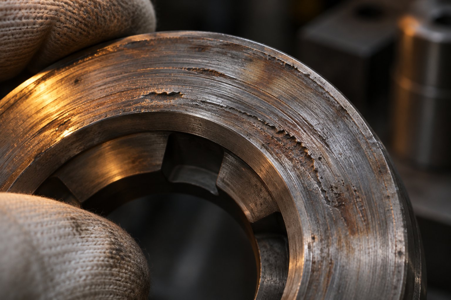
Diagnosing Screw Tip Wear and Knowing When to Replace
Here's the frustrating reality of screw tip wear: it doesn't announce itself. There's no alarm code, no flashing light on the controller, and no convenient pop-up telling you the check ring OD has lost three thousandths of an inch. Instead, degradation creeps in gradually — a slightly wider cushion spread this week, a few more light parts than last month, a vague sense that the process window that used to be comfortable is slowly shrinking. By the time the symptoms become obvious enough to trigger an investigation, the assembly has often been underperforming for weeks or months, silently bleeding quality and consistency from every shot.
Catching injection molding screw tip wear indicators early — before they compound into reject bins and emergency downtime — requires two things: knowing exactly what to look for on the physical components, and recognizing the production-floor signals that point back to the tip assembly as the root cause.
Visual and Dimensional Indicators of Screw Tip Wear
Every screw tip assembly follows a predictable wear progression. Understanding that progression turns a preventive maintenance inspection from a vague "looks okay" judgment into a structured evaluation that catches problems before they reach the parts.
The wear pattern typically develops in three areas simultaneously, each undermining a different aspect of seal integrity:
- Check ring OD erosion — The outer diameter of the check ring is the primary barrel-bore seal. Every cycle, this surface rides against the barrel wall under injection-phase pressures that can reach 20,000 to 45,000 psi. Over hundreds of thousands of cycles — especially with glass-filled or mineral-filled resins — the ring OD wears down, widening the annular gap between the ring and the barrel bore. That growing gap allows progressively more melt to leak past the outer seal during injection, even if the ring-to-seat seal is still in good condition.
- Seat surface washout — The contact surface where the check ring seats against the rear retainer takes the full force of every injection stroke. Over time, scoring, grooving, and localized washout develop along this mating face. Wear to the check ring or rear seat sealing surfaces, especially from exposure to unmelted material, compromises the metal-to-metal contact required for a positive shutoff. You'll often see a circumferential groove worn into the seat — a telltale sign that melt has been repeatedly washing past a seal that no longer closes cleanly.
- Tip body degradation — The screw tip's taper and flow-channel surfaces can round off, pit, or develop erosion patterns — particularly when processing abrasive compounds. As the tip body geometry deteriorates, the flow path during recovery becomes less predictable, increasing dead spots where resin stagnates and degrades.
During a scheduled screw pull, your visual inspection should focus on specific telltale signs: circumferential scoring on the ring and seat faces, galling marks from metal-to-metal contact under pressure, material buildup in dead zones around the tip body, and discoloration or blue-tinged areas that indicate localized overheating. Each of these visible clues maps to a specific failure mechanism that's actively degrading seal performance.
But here's the critical point many maintenance teams miss: visual inspection alone is not enough. Early-stage wear that's already affecting seal performance may be invisible to the naked eye. A check ring that looks clean and undamaged can still be several thousandths of an inch undersize on its OD — enough to allow significant leakage that shows up as cushion variation on the production floor.
Dimensional measurement with calibrated micrometers and bore gauges is essential. Measure the check ring OD at multiple points around its circumference and compare the readings to the original specification. Check the ring ID for ovality that would cause it to wobble on the tip body instead of sliding concentrically. Measure the seat diameters and use a protractor or optical comparator to verify the seat angle hasn't worn off its original geometry. If your facility runs abrasive resins, also gauge the barrel bore at the tip's operating position — a new ring ground to the original barrel spec won't restore sealing performance if the barrel itself has worn oversize.
This kind of quantitative screw tip check ring wear diagnosis transforms maintenance from reactive guesswork into data-driven decision-making. Record measurements at every inspection. Track trends over time. When dimensional wear approaches the threshold where seal function degrades — typically a few thousandths of an inch of diametral clearance beyond specification — you can schedule a replacement proactively rather than reacting to a quality crisis on the production floor.
Production Symptoms That Signal Replacement Is Needed
Even with the best inspection discipline, there will be times when production symptoms are the first indication that the tip assembly has crossed from acceptable wear into active process degradation. The challenge is that many of these symptoms overlap with other machine or process issues — which is why experienced technicians learn to recognize the pattern rather than chasing individual symptoms in isolation.
Watch for this cluster of warning signs, especially when they appear together or worsen progressively over a production run:
- Increasing cushion variation shot to shot — A healthy tip assembly produces a stable, repeatable cushion position at the end of each pack-hold phase. When the seal degrades, differing amounts of melt leak backward each cycle, causing the screw's final position to drift unpredictably. If your cushion readings swing by more than a few thousandths of an inch without any deliberate process change, the non-return valve assembly belongs at the top of your diagnostic checklist.
- Gradual rise in short shots or flash at previously stable settings — A process that ran clean for weeks or months and starts producing intermittent short shots is losing effective shot volume somewhere. Flash showing up at the same time — particularly on a different part of the mold than where the shorts occur — can signal that operators have compensated by raising injection pressure or shot size to overcome backflow losses, pushing material past the parting line elsewhere.
- Black specks or degraded material appearing in parts — Dead spots around a worn or pitted tip body trap resin that degrades over time. These carbonized particles periodically flush into the melt stream and show up as cosmetic defects in finished parts. If purging doesn't eliminate the problem, the contamination source is likely a physical hangup point in the tip geometry rather than a barrel or nozzle issue.
- Splay marks suggesting trapped gas or degraded resin — Silver streaks on part surfaces can indicate that volatiles released from degraded material in the tip assembly are being carried into the mold cavity with the melt stream. When splay appears inconsistently and doesn't respond to drying adjustments or vent cleaning, a worn tip with degradation-prone dead zones is a strong suspect.
- Longer recovery times — A tip body with eroded flow channels or a ring that doesn't slide freely creates additional restriction during recovery, slowing the rate at which melt can pass forward and build the next shot. If recovery time has crept up without any change to screw speed, back pressure, or material, the flow path through the tip assembly may be compromised.
- Inability to maintain consistent part weight — This is the downstream summary of all the above symptoms. A cushion that slowly decreases or fluctuates during production should not simply be corrected by repeatedly adding more shot size — that approach masks the root cause while the leaking assembly continues to deteriorate.
When multiple symptoms from this list appear simultaneously, the probability that the screw tip assembly is the root cause rises sharply. However, confirming the diagnosis still requires pulling the screw for physical inspection. Process data alone can suggest the problem — dimensional measurement confirms it.
A practical diagnostic approach: before committing to a full screw pull, run a dynamic check ring test — a procedure that evaluates how well the non-return valve holds pressure under actual injection conditions. Inconsistent pressure-hold results point directly to a compromised seal and justify the downtime required to extract and inspect the screw assembly.
Replace Versus Repair Decisions
You've pulled the screw, measured the components, and confirmed that the tip assembly has worn past its functional limits. The next question is practical: replace or rebuild?
Rebuilding — re-chroming a worn check ring OD, welding and regrinding seat surfaces, or re-hardening a tip body — is sometimes viable, particularly for large-diameter assemblies where replacement components carry significant cost. Re-chroming can restore the ring OD to specification if the base metal underneath is still structurally sound and dimensionally stable. Weld repair of seat surfaces works when the washout is shallow and the retainer body retains enough material to support a regrind to the correct angle.
Full replacement makes more sense when:
- Wear has progressed past the point where rebuilding would leave adequate material thickness for reliable service
- The base metal shows pitting, corrosion, or cracking that compromises structural integrity
- Multiple components in the assembly — ring, seat, and tip body — have all worn beyond tolerance simultaneously, making a matched replacement set more cost-effective than rebuilding each piece individually
- The original material of construction was wrong for the resin being processed, and the replacement is an opportunity to upgrade to a more appropriate alloy or surface treatment
In practice, for small- and medium-diameter screw assemblies, replacement is almost always the faster and more economical path. The labor cost of disassembly, shipping to a rebuilder, waiting for turnaround, and reinstallation often exceeds the price of a new matched component set — especially when you factor in the production downtime during the rebuild cycle.
Whichever path you choose, speed and accuracy in the sourcing process depend on having the right information ready. Maintenance teams that keep dimensional records, original drawings, and photos of worn assemblies on file can move from diagnosis to replacement with minimal delay. When drawings or part numbers aren't available — which is common on older machines or equipment purchased secondhand — a worn sample paired with measured dimensions gives a qualified manufacturer everything needed to produce an accurate replacement.
Suppliers like NANHAIYA follow exactly this workflow: they review machine details, drawings, worn samples, photos, and measured dimensions to assess part compatibility and manufacturing feasibility before quoting. Their spare parts catalog includes screw tips, check rings, and non-return valves — the core components of the tip assembly — which streamlines the process of sourcing a matched replacement set from a single source rather than coordinating across multiple vendors.
Regardless of supplier, always request material certifications and dimensional inspection reports for finished components. Verify hardness testing results against the specification for your resin application. And before the new assembly goes into production, perform the bench-level fit check described in the installation section: confirm the ring slides freely on the tip body, verify OD clearance against the actual barrel bore, and check seat-angle contact with marking compound. Five minutes of verification at the workbench prevents discovery of a mismatch during startup — when the cost of getting it wrong multiplies by the hour.
Recognizing wear and acting on it promptly keeps the tip assembly functioning as the precision seal it's designed to be. But understanding what happens downstream when that seal degrades — the specific molding defects that trace directly back to a worn or mismatched screw tip — gives process engineers the diagnostic framework to connect production-floor symptoms to their mechanical root cause before those symptoms escalate into systemic quality problems.
How Screw Tip Condition Drives Molding Defects
Picture this: a mold that ran flawlessly for months suddenly starts producing intermittent short shots. The process engineer checks temperatures, adjusts transfer positions, bumps up pack pressure — and the problem seems to improve for a shift, then returns. A second engineer suspects the hot runner and spends half a day pulling tips and cleaning gates. Still no lasting fix. Three weeks and thousands of dollars in scrap later, someone finally pulls the screw and finds a check ring that's lost four thousandths on its OD. The culprit was never the process or the mold. It was the seal.
That scenario plays out in molding shops constantly, because the connection between injection molding defects and screw tip wear isn't intuitive. The defect shows up at the part. The root cause lives inside the barrel, invisible and unmeasured. Bridging that gap — linking specific defect types to their mechanical origin in the tip assembly — is the diagnostic shortcut that saves process engineers from chasing symptoms instead of solving problems.
Short Shots, Cushion Drift, and Inconsistent Part Weight
The mechanism here is direct and mechanical. A worn check ring or eroded seat surface allows molten resin to leak backward past the assembly during injection and pack-hold. That backflow reduces the effective volume of plastic delivered to the cavity and diminishes the packing pressure that compensates for volumetric shrinkage as the part cools. The result? The mold doesn't receive enough material to fill completely, or it fills but doesn't pack adequately — producing parts that are dimensionally off, visually incomplete, or underweight.
What makes this defect particularly deceptive is its progressive nature. A screw tip causing short shots in injection molding rarely fails all at once. Instead, the leakage increases gradually as wear accumulates. Early on, the process window is wide enough to absorb the loss — the cushion shifts slightly, but parts still pass inspection. Over a production run, as the assembly heats up and thermal expansion widens clearances further, the leakage rate climbs. You'll notice cushion readings drifting forward shot to shot, part weights trending downward, and eventually intermittent short shots appearing on the thinnest wall sections or at the end of the flow path.
A common troubleshooting mistake is to compensate by increasing shot size or injection pressure. That temporarily masks the symptom — but it also raises clamp-force demands, increases the risk of flash on other areas of the part, and accelerates wear on the already-degraded seal surfaces. The compensation creates a feedback loop: more pressure forces more melt past the worn seal, which requires even more compensation, which drives even faster wear. Meanwhile, the process window that was once comfortable shrinks to a razor-thin band where any minor variation in material viscosity or ambient temperature tips the balance toward rejects.
Flash appearing simultaneously with short shots is a strong diagnostic signal. When operators add pack pressure to overcome backflow losses, that extra pressure may exceed what the mold clamp can contain at thin parting-line areas — producing flash on some cavities while others still run short. If you're seeing both defects on the same run without a clear process explanation, the non-return valve assembly deserves immediate investigation.
Black Specks, Splay, and Degraded Material Defects
Not every defect tied to the tip assembly involves backflow. Some originate from the geometry of the tip itself — specifically, from dead spots where resin stagnates, overheats, and degrades.
Every screw tip design creates some internal flow path that resin must navigate during recovery. In a well-engineered sliding ring assembly with streamlined channels, melt sweeps cleanly around the tip body with minimal hang-up. But in ball check and poorly designed poppet valves, the internal housing that cradles the ball or poppet creates recessed pockets. Resin trapped in these pockets doesn't participate in the normal flow cycle. Instead, it sits at barrel temperature — or higher, thanks to shear heating — for extended periods, slowly degrading.
Over time, that trapped material carbonizes. Periodically, a shift in flow dynamics during recovery or a change in back pressure dislodges a fragment of this carbonized residue, flushing it into the melt stream. It shows up in the finished part as a black speck — a dark, brittle inclusion embedded in or streaked across the surface. As one detailed diagnostic guide explains, these specks from a worn screw tip assembly tend to appear as brownish-black streaks that are smeared and fused with the base plastic, distinguishing them from foreign contamination particles that have sharp, defined edges.
A worn tip body compounds the problem. Pitting, erosion grooves, and rounded flow channels create new stagnation zones that didn't exist when the component was new. Even a sliding ring design — normally the cleanest flow path of any tip type — can develop dead spots as its surfaces degrade. If purging eliminates black specks temporarily but they return within a few hundred shots, the source is almost certainly a physical hang-up point inside the tip geometry rather than a barrel, nozzle, or material-handling issue.
Splay — those silver streaks or splash marks on part surfaces — follows a related but distinct mechanism. When melt passes through narrow or misaligned flow channels around a damaged tip, localized shear rates spike. That excessive shear generates heat in the resin itself, not from the barrel heaters but from internal friction within the polymer. Heat-sensitive resins respond by releasing volatiles — moisture, monomers, or decomposition byproducts — that become trapped as gas bubbles in the melt front. When that gas-laden material enters the cavity and flows across the part surface, it produces the characteristic silver streaking pattern.
The diagnostic clue? Splay caused by tip-related shear degradation typically appears inconsistently and doesn't respond to the usual fixes — increasing drying time, lowering melt temperature, or cleaning mold vents. If those standard interventions fail to resolve the issue, the flow path through the screw tip assembly is a strong suspect.
Burn Marks and Stringing Connected to Tip Condition
Burn marks — dark or charred areas on part surfaces — are usually associated with trapped air in the mold or excessive melt temperatures. But a damaged screw tip can create burn conditions entirely within the barrel, before the melt ever reaches the nozzle.
The mechanism involves obstructed flow. When erosion, pitting, or material buildup partially blocks the flow channels around the tip, the melt is forced through a tighter effective cross-section. The resulting pressure spike generates adiabatic heating — a rapid temperature rise caused by compression rather than conduction from the barrel heaters. In severe cases, this localized overheating exceeds the resin's thermal stability limit, producing degraded or charred material that enters the mold as visible burn marks on the part surface. Increased shear heat from excessive screw wear and material degradation from prolonged residence time in a worn assembly are both well-documented contributors to burn defects that can't be corrected through machine settings alone.
Stringing — thin filaments of plastic that trail from the sprue or gate when the mold opens — traces back to the opposite end of the seal problem. A tip assembly with excessive leakage can't maintain a clean pressure shutoff at the end of hold. Residual pressure in the melt channel ahead of the tip pushes material forward through the nozzle even after the hold phase ends, creating nozzle drool. When the mold opens and the part ejects, that drooled material stretches into strings that cling to the mold surface. As injection molding tooling experts have documented, strings tend to be static charged and stick to the mold — and if they hang over the parting line, they can hob even heat-treated steel tooling, eventually causing flash that requires an expensive mold rebuild.
A tip assembly that seals properly eliminates one of the key upstream contributors to drool-driven stringing. If stringing appears or worsens on a machine that previously ran clean, and nozzle temperature adjustments don't resolve it, the check ring's ability to hold back-pressure during the decompression and mold-open phases may have degraded past its functional limit.
Defect-to-Root-Cause Diagnostic Reference
The table below maps common molding defects to their screw-tip-related mechanisms and the recommended diagnostic actions. Use it as a quick-reference tool on the production floor to determine whether the tip assembly should be investigated before — or alongside — other process and tooling variables.
| Defect | Screw Tip Root Cause | Mechanism | Recommended Action |
|---|---|---|---|
| Short shots | Worn check ring OD or eroded seat surfaces | Backflow during injection reduces effective shot volume | Run dynamic check ring test; pull screw and measure ring OD and seat surfaces against specification |
| Cushion drift / part-weight variation | Progressive seal degradation across check ring and seat | Variable leakage flow shifts cushion position shot to shot | Monitor cushion trend data; compare to historical baseline; inspect assembly if variation exceeds acceptable range |
| Flash at stable settings | Operators compensating for backflow losses by raising pressure | Increased injection or pack pressure exceeds clamp force at thin parting-line areas | Check whether pressure settings have been gradually increased; correlate with cushion position changes |
| Black specks | Dead spots in tip geometry trapping and degrading resin | Carbonized material periodically flushes into melt stream | Purge and observe if specks return within a few hundred shots; if yes, pull screw and inspect tip for pitting, buildup, or stagnation zones |
| Splay (silver streaks) | Narrow or misaligned flow channels around damaged tip | Excessive localized shear generates volatiles from polymer degradation | Rule out moisture and vent issues first; if splay persists, inspect tip flow-channel geometry for erosion or restriction |
| Burn marks | Obstructed flow paths from erosion or material buildup | Pressure spikes create adiabatic heating beyond resin stability limit | Inspect tip for partially blocked channels, embedded material, or severe surface erosion |
| Stringing / nozzle drool | Excessive leakage preventing clean pressure shutoff | Residual melt pressure pushes material through nozzle after hold phase ends | Evaluate decompression settings; if stringing persists, test check ring sealing integrity |
| Longer recovery time | Eroded tip flow channels or restricted ring travel | Increased restriction during recovery slows melt passage past tip | Compare current recovery time to historical baseline; inspect ring travel and channel geometry if degraded |
Notice how many of these defects can coexist on the same machine running the same mold. A single worn assembly can simultaneously produce cushion drift, intermittent shorts, occasional black specks, and a gradual uptick in recovery time — a constellation of symptoms that, taken individually, each point to different process variables. It's only when you step back and see the pattern — multiple symptoms trending worse together, unresponsive to process adjustments — that the tip assembly emerges as the common thread connecting them all.
That diagnostic clarity is valuable, but it still leaves a practical question: once you've confirmed the assembly needs replacement, how do you source the right one quickly and confidently — especially when original drawings may be missing and the machine is sitting idle, burning downtime by the hour?
Sourcing Replacement Screw Tip Assemblies with Confidence
The machine is down, the worn assembly is on the bench, and the clock is running. Every hour spent chasing compatibility questions, waiting for clarification from suppliers, or discovering a dimensional mismatch after delivery is an hour of lost production. The difference between a smooth replacement cycle and a drawn-out procurement headache almost always comes down to preparation — specifically, how much usable information you have ready before you ever pick up the phone or submit a quote request.
What Information to Gather Before Requesting a Quote
Think of the quoting process like handing a machinist a blueprint. The more complete and precise that blueprint is, the faster and more accurate the result. Missing details force back-and-forth exchanges that stretch lead times and increase the risk of receiving a part that doesn't fit. Before contacting any supplier for a replacement injection molding screw tip assembly, work through this preparation checklist:
- Record the machine make, model, and screw diameter. This gives the supplier an immediate reference point for thread specifications, barrel bore dimensions, and any OEM-specific design features that affect compatibility.
- Obtain original OEM drawings or part numbers if available. Even partial documentation — a faded drawing from the machine manual or a part number stamped on the old retainer — can save days of reverse-engineering effort.
- Measure critical dimensions of the existing assembly. Use calibrated instruments to capture thread size and pitch, tip overall length, check ring outer diameter, inner bore diameter, and rear seat angle and diameter. These measurements are your ground truth, especially when OEM documentation is missing.
- Photograph the worn assembly from multiple angles showing wear patterns. Close-up images of seat washout, ring OD erosion, thread condition, and any pitting or buildup give the supplier visual context that raw dimensions alone can't convey. Include a scale reference — even a ruler laid next to the part — for size confirmation.
- Note the resin types being processed and any abrasive or corrosive fillers. This information drives the material-of-construction recommendation. A supplier who knows you're running 30% glass-filled nylon will quote a different alloy than one who assumes you're processing unfilled ABS.
Thorough documentation prevents compatibility errors, eliminates unnecessary back-and-forth, and compresses the quoting cycle from days down to hours. It also protects you — when every critical dimension is recorded and shared upfront, responsibility for a mismatch shifts clearly to the manufacturing side rather than falling into a gray zone of incomplete specifications.
Evaluating Aftermarket and OEM Replacement Options
When it's time to source the actual components, you'll face a familiar tradeoff. OEM replacement parts offer a guaranteed dimensional match to the original assembly — the part number is in their system, the drawings are on file, and compatibility is essentially a given. The downside? OEM parts often carry premium pricing and longer lead times, particularly for older machine models where inventory isn't stocked and production runs are made to order.
Aftermarket manufacturers who specialize in injection molding machine components can frequently match or improve on OEM specifications — sometimes with shorter lead times and lower cost — but the burden of verifying compatibility shifts to the buyer-supplier relationship. This is where the preparation work pays off. A reputable aftermarket screw tip injection molding machine supplier won't simply take your order and ship a part. They'll request your machine details, review your drawings or worn samples, and confirm dimensional compatibility and material suitability before committing to manufacture.
NANHAIYA, for example, follows exactly this workflow. Their catalog of injection molding spare parts — including screw tips, check rings, non-return valves, injection nozzles, and thermocouples — gives maintenance teams and equipment rebuilders a starting point for identifying where to buy injection molding screw tips and related components. Before quoting, their team reviews the machine details, drawings, worn samples, photos, and dimensions you provide, assessing part compatibility and manufacturing feasibility rather than simply matching a generic part number. That verification step mirrors the best-practice sourcing process outlined throughout this article.
Regardless of whether you go OEM or aftermarket, apply the same quality-verification discipline to every supplier:
- Request material certifications that confirm the alloy grade and heat-treatment condition match what was specified for your resin application.
- Review dimensional inspection reports for finished components — particularly check ring OD, seat angle, and thread dimensions — to verify they fall within the tolerances required for proper seal function.
- Verify hardness testing results against the specification appropriate for your operating conditions. A tip rated for unfilled commodity resins won't survive long in a glass-filled environment, no matter how precisely it was machined.
One final practical note: whenever possible, source the complete assembly — tip body, check ring, and rear seat — as a matched set from a single supplier. Mixing components from different manufacturers introduces the risk of subtle dimensional mismatches between the ring and seat or the ring and tip body that compromise sealing performance even though each individual piece meets its own print. A matched set, built and inspected as a unit, eliminates that variable entirely.
The injection molding screw tip sits at the intersection of material science, precision machining, and real-world process demands. It's small enough to hold in one hand and consequential enough to determine whether your machine produces consistent, profitable parts or bleeds quality on every shot. Armed with the diagnostic, selection, installation, and sourcing knowledge covered throughout this guide, you're equipped to treat this critical component with the attention it deserves — and to catch the hidden wear that triggers costly defects long before those defects reach your customers.
Frequently Asked Questions About Injection Molding Screw Tips
1. How often should an injection molding screw tip assembly be inspected?
Inspection frequency depends on the resin being processed and production volume. For abrasive glass-filled or mineral-filled resins, inspect the screw tip assembly during every scheduled screw pull — typically every 500 to 2,000 operating hours. Unfilled commodity resins like polypropylene or ABS are less demanding, so inspections every 3,000 to 5,000 hours are often sufficient. Between screw pulls, monitor cushion stability, part weight consistency, and recovery time as indirect indicators of seal condition. If cushion variation exceeds your historical baseline or multiple defect symptoms appear together, an early inspection is warranted regardless of the scheduled interval.
2. What is the difference between a sliding ring and a ball check screw tip?
A sliding ring (free-flow) screw tip uses a three-piece assembly where a check ring slides axially along the tip body to open and close the melt path. It offers low pressure drop, minimal dead spots, and does not rotate against the barrel bore, which protects barrel life. A ball check tip replaces the ring with a spring-loaded or gravity-seated ball inside an internal housing. Ball checks can seal faster, which benefits very small shot sizes or low-viscosity resins, but they create higher pressure drop, more stagnation zones prone to resin degradation, and their housing rotates with the screw — accelerating barrel wear. For general-purpose molding, sliding ring assemblies remain the most versatile and cost-effective choice.
3. Can a worn screw tip cause black specks in injection molded parts?
Yes. A worn or pitted screw tip creates dead spots where molten resin stagnates and eventually carbonizes from prolonged exposure to barrel temperatures. These carbonized particles periodically dislodge and flush into the melt stream, appearing as dark specks or brownish-black streaks in finished parts. Ball check and poppet-style tips are especially prone to this issue because their internal housings trap resin more readily. If purging temporarily eliminates black specks but they return within a few hundred shots, the contamination source is likely a physical hang-up point in the tip geometry rather than a barrel or material-handling problem.
4. What anti-seize compound should be used when installing a screw tip?
Use a high-temperature nickel-based or copper-based anti-seize compound rated for the barrel's operating temperature range. Nickel-based formulations are rated to approximately 2,400 degrees Fahrenheit, making them the safest all-around choice for injection molding barrels that routinely reach 400 to 700 degrees Fahrenheit or higher. Avoid general-purpose zinc or aluminum compounds rated only for ambient or moderate temperatures. Keep in mind that anti-seize acts as a lubricant and reduces thread friction by roughly 20 to 30 percent, so you must reduce the applied torque accordingly using the anti-seize manufacturer's K-factor guidance to avoid overtightening the assembly.
5. How do I source a replacement screw tip if I don't have the original drawings?
When original OEM drawings or part numbers are unavailable, gather five key pieces of information: the machine make, model, and screw diameter; measured dimensions of the existing assembly including thread size, tip length, check ring OD, and seat angle; photographs of the worn components from multiple angles with a scale reference; and the resin types being processed. Reputable suppliers like NANHAIYA review these machine details, worn samples, photos, and measured dimensions to assess part compatibility and manufacturing feasibility before quoting. Providing a complete worn sample alongside your measurements gives the manufacturer everything needed to reverse-engineer an accurate replacement without original documentation.
Written by
Nanhaiya Technical Team
Zhoushan Nanhaiya Plastic Machinery Co., Ltd.
The Nanhaiya technical team supports screw and barrel manufacturing projects through application review, technical communication, custom manufacturing coordination, and production and quality control.
Discuss Your Application
Related Articles
More insights on screw barrel technology and plastics processing.
Still Chasing Black Specks? Purging Plastic Needs a Full Rethink
Nov 6, 2026
Learn how purging plastic cuts scrap, downtime, and rejects. Compare all purging methods, match compounds to resins, and build a preventive program that works.
Read Article
Stop Chasing Symptoms: Fix Injection Molding Splay at the Source
Nov 6, 2026
Learn what causes injection molding splay, how to diagnose moisture, shear, and degradation splay by location, and fix silver streaks at the root cause.
Read Article
Your Injection Molding Cushion Is Drifting — Here's Why
Nov 6, 2026
Injection molding cushion drifting? Learn what causes it, how to set the right cushion size by resin and machine, and a root-cause framework to fix it fast.
Read ArticleLooking for something else?
Search by material, symptom or product and jump straight to the relevant page.
These are navigation suggestions based on keyword matching — not a quotation, not a delivery commitment, and not a substitute for engineering review. Final specification is confirmed by our engineers against your drawings and processed material.
Need help with screw barrel selection?
Share your machine model, processed material and application. Our team can help with pricing and technical support.