

What Exactly Is Cushion in Injection Molding
Ask five molding professionals to define cushion in injection molding and you may get three different answers. The confusion is real, and it starts with how different machine manufacturers display screw position data on their controllers. Before you can diagnose cushion variation in injection molding, you need a rock-solid understanding of what cushion actually means — and where the competing definitions come from.
Resolving the Two Definitions of Cushion
Here is where the terminology splits. Some machine manufacturers report cushion as the screw's most forward position during the entire injection cycle — typically reached at the end of the fill stage. Others define it as the screw position at the end of the pack-and-hold phase. These two values can differ significantly. When a machine transfers from high-speed fill to a lower hold pressure, the screw can drift backward if cavity pressure pushes against it. That drift creates a measurable gap between the "farthest forward" reading and the "end of hold" reading.
As injection molding expert Robert Gattshall explains in Plastics Technology, machine manufacturers do not all measure cushion the same way — some use terms like "screw end position" or "screw forward position" instead. Some controllers provide only the most forward position, while others show both the most forward position and the end-of-hold position. The preferred approach for process control is monitoring the screw position at the end of the hold stage, because that value reflects the actual melt pad available throughout the packing phase.
Cushion is the distance of molten plastic remaining in front of the screw tip at the end of the hold/pack phase, measured as a linear value (typically in millimeters or inches). It represents the melt reservoir that transmits packing pressure into the mold cavity.
How Screw Position Determines Cushion Distance
To make sense of this measurement, imagine what the screw does during a single molding cycle. During recovery, it rotates like a conveyor, pulling resin pellets forward through the heated barrel. Molten plastic accumulates in front of the screw tip, pushing the screw backward. Once enough material has been metered — your shot size — the screw stops rotating. During injection, the screw reverses its role entirely. It stops turning and drives forward like a plunger, forcing that accumulated melt through the nozzle, runner system, and into the mold cavity.
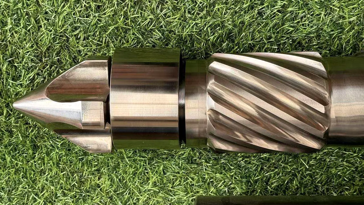
The non-return valve (check ring) seated at the screw tip prevents melt from leaking backward past the screw flights during this forward plunger stroke. When the cavity is nearly full and the machine transitions to hold pressure, the screw continues pressing forward at a controlled pressure to pack the part. The small column of melt still sitting in front of the screw tip at the end of this packing stage is your cushion. It acts as a hydraulic bridge — connecting the screw's pressure to the melt inside the mold. Without it, the screw bottoms out and can no longer transmit pressure into the cavity.
Melt Cushion vs. Cushion — Are They the Same
You will encounter both "melt cushion" and "cushion" in technical literature, on machine screens, and in training courses. They refer to the same thing. The term "melt cushion" simply emphasizes that this remaining pad is molten plastic, not solid pellets. RJG consultant Jim Clifford defines it clearly: the material left at the front of the screw when the screw is in the forward position is the melt cushion, and for conventional injection molding, it must never reach zero.
Why does zero matter? Because the cushion is what enables you to build cavity pressure during the hold phase. Once the screw hits bottom with nothing left to push on, hold pressure becomes meaningless — it cannot reach the part. The result is erratic cavity pressure from shot to shot, which translates directly into dimensional scatter, weight inconsistency, and surface defects. This is precisely why cushion variation in injection molding deserves closer attention than cushion size alone. A process can have the "right" cushion target and still produce scrap if that target drifts from cycle to cycle.
The real question, then, is not just whether you have a cushion — it is whether that cushion stays consistent enough to deliver repeatable packing pressure into every shot. That consistency depends on factors ranging from the material you are running to the mechanical condition of the screw and barrel assembly.
Why Cushion Size and Stability Drive Part Quality
Knowing what cushion is only gets you halfway. The deeper question is this: how does that small pad of molten plastic sitting in front of your screw actually shape the quality of every part leaving your mold? The answer lies in pressure transfer — and more importantly, in how consistently that pressure reaches the cavity from one shot to the next.
How Cushion Controls Packing Pressure Transfer
Plastic shrinks as it cools inside the mold. During the hold phase, the screw continues pressing forward against the melt cushion, forcing additional material through the gate to compensate for that volumetric shrinkage. Think of the cushion as a hydraulic link between the screw tip and the melt inside the cavity. Remove that link — let the screw bottom out — and the hold pressure displayed on your controller becomes a phantom number. The machine may show 800 psi, but none of it is reaching the part.
This relationship governs several critical quality attributes at once. Consistent packing pressure fills out thick sections around ribs and bosses, preventing sink marks. It stabilizes part weight by delivering the same volume of material into the cavity every cycle. It controls dimensional accuracy by ensuring uniform density and shrinkage. And it influences surface finish, because underpacked areas often show gloss differences or witness lines where the skin layer did not replicate the mold texture fully.
As Suhas Kulkarni of Fimmtech illustrates, the concept is similar to a piston-and-chamber system: fluid must exist in the upper chamber for force to transfer through the connector to the lower chamber. No fluid, no pressure — regardless of how hard you push the piston. In injection molding terms, no cushion means no effective packing, even if the machine is commanding full hold pressure.
There is also a compressibility factor worth noting. Molten plastic behaves somewhat like a ball of compressed rubber bands. A cushion that is excessively large absorbs part of the applied hold pressure simply compressing the melt in front of the screw, rather than transmitting it into the cavity. This is especially significant with high-viscosity or highly filled materials, where a bloated cushion can quietly steal packing force and introduce injection molding cushion variation from shot to shot.
Starting Cushion Size Guidelines and When to Adjust Them
When you are setting up a new process, you need a starting point. The commonly cited injection molding cushion size guideline is approximately 3-6 mm (roughly 0.12-0.24 in.) for screw diameters in the 25-60 mm range. This range appears frequently in industry training and process development references as a practical starting target.
But here is the nuance many guides skip: a 4 mm cushion on a 25 mm screw contains far less melt volume than 4 mm on a 60 mm screw. The same linear distance does not represent the same material reservoir across different machines. That is why machine manufacturer recommendations should always take priority over generic rules of thumb. Some experienced molders also use a percentage-of-shot-size approach, but Kulkarni cautions that there is no real basis for percentage-based rules once you understand the fundamental purpose of the cushion.
The right cushion size also depends heavily on the specific molding scenario. The table below outlines common application contexts and the factors that push your starting value up or down:
| Application Context | Typical Starting Cushion Range | Key Adjustment Factors |
|---|---|---|
| Thin-wall packaging or consumer goods | 2-4 mm (some processes run with zero cushion intentionally) | High fill speeds, high cavity pressures, and warpage sensitivity may favor minimal or no cushion to reduce molded-in stress |
| Standard injection molded parts (mid-wall) | 3-6 mm | Adjust based on screw diameter, part weight relative to barrel capacity, and gate size |
| Thick-walled or precision-dimension parts | 5-8 mm | Extended hold times require a reliable melt reservoir; larger cushion prevents screw from bottoming out during long packing stages |
| Multi-cavity or family molds | 4-7 mm | Cavity-to-cavity fill balance and runner volume affect how much melt is consumed during hold; unbalanced molds need more cushion margin |
| Heat-sensitive resins (PVC, POM) | 3-5 mm (keep small) | Excess cushion increases residence time in the hottest barrel zones, risking degradation — the nozzle area plastic forms the skin of the runner and potentially the part |
Notice that thin-wall parts sometimes run with no cushion at all. As Robert Gattshall explains, running without a cushion significantly reduces molded-in stress, which is critical for parts prone to warping or long-term cracking. Plunger-style machines designed to bottom out every shot are purpose-built for this approach. The point is that the 3-6 mm guideline is a starting framework, not a universal mandate.
The Shift from Cushion Size to Cushion Stability
Here is where many molding operations miss the bigger picture. You can spend hours dialing in the perfect injection molding cushion size, but if that value wanders by a millimeter or more from shot to shot, your parts will still vary. A stable 4 mm cushion is far more useful than a reading that jumps between 2 mm and 6 mm across consecutive cycles.
Why? Because an inconsistent cushion means an inconsistent volume of plastic is being delivered to the cavity each cycle. When the cushion changes, the effective packing pressure reaching the part changes with it. That translates to weight scatter, dimensional drift, and cosmetic inconsistency — sometimes subtly enough that you do not catch it until a downstream assembly fails or a customer inspection report arrives.
Kulkarni recommends setting alarm limits around the cushion value, with typical tolerances of roughly +/-0.05 in. (about 1.3 mm), though these should be established based on the specific part's dimensional requirements — ideally through a design of experiments (DOE) study rather than arbitrary defaults. Monitoring that variation over time reveals far more about your process health than a single snapshot reading ever could.
This distinction — between having a cushion and having a stable cushion — is the pivot point for everything that follows. Injection molding cushion variation is not just a number on a screen. It is a leading indicator of developing problems, from worn check rings to shifting material properties, that quietly erode part quality before a single reject ever hits your sorting bin.
Acceptable vs Unacceptable Cushion Variation by Application
So your cushion drifts by half a millimeter from shot to shot. Is that a crisis or a non-issue? The honest answer is: it depends entirely on what you are molding. A storage bin lid and a surgical catheter housing may both run on the same tonnage machine, but they live in completely different worlds when it comes to how much melt cushion injection molding variation the process can tolerate before parts fail inspection.
How Application Criticality Sets Variation Thresholds
Tighter part tolerances demand tighter cushion repeatability — that principle is straightforward. What trips up many processors is quantifying what "tight enough" actually looks like for their specific application. A medical device manufacturer working under ISO 13485 requirements faces dimensional tolerances measured in hundredths of a millimeter. Even a small swing in the material cushion injection molding process introduces enough packing variation to push critical dimensions outside their control limits. Optical components — lenses, light guides, display covers — are similarly unforgiving, because density gradients from inconsistent packing show up as refractive distortion or birefringence.
Automotive structural parts occupy a middle tier. They carry meaningful safety requirements and dimensional specifications, but their wall sections are often thicker and more forgiving of minor packing fluctuations. General consumer goods sit at the other end of the spectrum. A plastic hangar or food container can typically absorb more shot-to-shot cushion swing before the variation becomes visible or functionally relevant.
The table below maps these application tiers against practical variation guidelines. Where tighter numerical thresholds exist in published process development literature, those values are reflected. For less-documented categories, the principle holds: the higher the consequence of a nonconforming part, the narrower the acceptable cushion window.
| Application Tier | Typical Acceptable Cushion Variation Range | Primary Quality Concern | Monitoring Frequency |
|---|---|---|---|
| Medical / Precision Optics | +/- 0.02 in. (approx. +/- 0.5 mm) or tighter, validated through DOE | Dimensional accuracy, density uniformity, regulatory compliance | Every shot — continuous SPC with automatic alarm limits |
| Automotive Structural / Safety | +/- 0.03-0.04 in. (approx. +/- 0.8-1.0 mm) | Mechanical strength, weight consistency, assembly fit | Every shot monitored; periodic SPC review per shift |
| General Consumer / Non-Critical | +/- 0.05 in. (approx. +/- 1.3 mm) — the commonly cited default tolerance | Cosmetic appearance, basic dimensional fit, sink marks | Periodic spot checks; alarm-based monitoring acceptable |
The +/- 0.05 in. tolerance referenced in industry training by Suhas Kulkarni is a reasonable default, but he emphasizes that it must be set based on the specific part's dimensional requirements — ideally through a design of experiments (DOE) study. For medical and precision applications, that default is often far too loose.
Linking Cushion Variation to Part Weight Scatter
Imagine your cushion reading jumps from 4.5 mm on one shot to 3.0 mm on the next. That 1.5 mm difference means the screw traveled further forward on the second shot, pushing more material into the cavity. The result? A heavier part with different dimensions, different shrinkage behavior, and potentially different mechanical properties. Scale that across a multi-cavity mold and the scatter compounds.
This is exactly why part weight changes alongside cushion — the two are directly linked. When cushion varies, the effective volume of melt packed into the cavity changes. Weight variation becomes the measurable fingerprint of inconsistent cushion. For processors wondering how to increase cushion injection molding stability, the first step is recognizing that weight scatter on your scale often traces back to what the screw position was doing during hold.
When Variation Signals a Developing Problem
A stable process does not suddenly start producing erratic cushion readings for no reason. When your trend chart shows the variation band widening — even if individual shots still fall within alarm limits — something in the system is changing. Maybe a check ring is beginning to seat inconsistently. Maybe a heater band is starting to fail, creating viscosity swings. Maybe a new resin lot arrived with a slightly different melt flow index.
The pattern of the variation matters as much as its magnitude. A gradual widening of the shot-to-shot spread over days or weeks points toward progressive mechanical wear. A sudden jump to wider scatter after a material change suggests a viscosity mismatch. Erratic, random variation that appears and disappears hints at intermittent problems — a check ring that seats properly on some shots but not others, or moisture levels that fluctuate with dryer performance.
Recognizing these patterns early — before parts actually fail inspection — is what separates reactive troubleshooting from proactive process control. But pattern recognition requires a framework: a systematic way to trace cushion drift back to its root cause rather than chasing symptoms at random.
A Root Cause Framework for Diagnosing Cushion Drift
Most troubleshooting guides hand you a flat list of possible causes and tell you to start checking. The problem? That list might contain fifteen items spread across completely different systems — worn check rings sitting next to incorrect back pressure settings sitting next to moisture content issues. Without a map, you end up guessing where to look first. And guessing, in a production environment, means wasted machine time, wasted material, and parts that keep drifting while you chase the wrong lead.
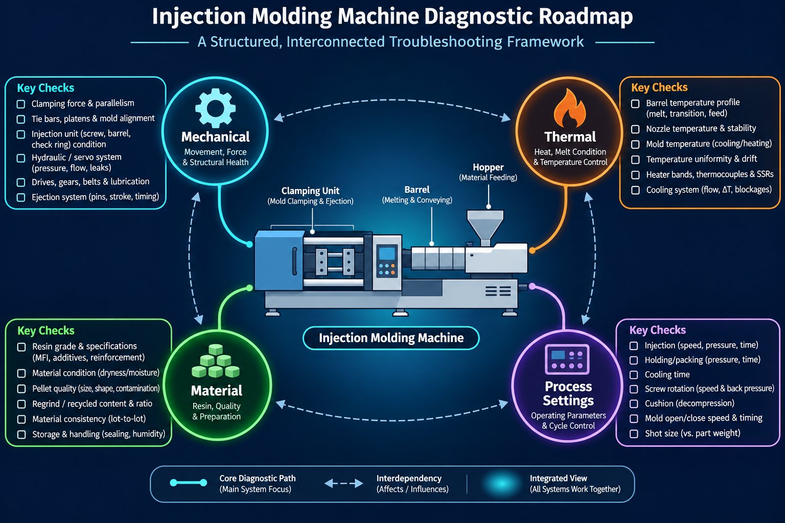
A more effective approach organizes every cause of injection molding cushion variation into distinct categories based on the system they belong to. When you understand what is cushion in injection molding — a melt pad whose stability depends on mechanical sealing, thermal consistency, material uniformity, and process settings working together — you can see that a problem in any one of those four systems will show up as cushion drift. The key is figuring out which system to investigate first.
Four Root Cause Categories for Cushion Variation
Every source of cushion instability falls into one of four categories: Mechanical, Thermal, Material, or Process Settings. Think of these as four branches of a diagnostic tree. Each branch has its own failure modes, its own symptoms, and its own verification methods. The table below lays out this framework at a glance — a reference you can bring to the press floor and use as a starting checklist before touching a single parameter.
| Category | Common Causes | Primary Diagnostic Method |
|---|---|---|
| Mechanical | Check ring (non-return valve) wear, barrel bore wear, screw flight wear, nozzle tip and seat leakage | Cushion position trending over time; shut-off nozzle leak test; physical inspection of screw assembly and barrel bore measurements |
| Thermal | Barrel temperature zone deviations, heater band degradation or failure, thermocouple drift, inadequate soak time after startup | Compare actual zone temperatures against setpoints; heater band resistance checks; thermocouple calibration verification |
| Material | Lot-to-lot viscosity variation, inconsistent moisture content, regrind ratio changes, amorphous vs. semi-crystalline behavior differences, filler loading shifts | Incoming material verification (melt flow index, moisture analysis); regrind ratio audits; lot-change documentation review |
| Process Settings | Back pressure drift or instability, shot size errors, excessive or inconsistent decompression (suck-back), injection speed profile changes | Compare current machine settings against validated process sheet; back pressure verification at the gauge; shot size audits |
Notice how the categories move from the physical machine outward. Mechanical issues involve the hardware that seals and moves the melt. Thermal issues involve the energy input that keeps the melt at the right viscosity. Material issues involve the feedstock itself. Process settings involve the parameters that a technician or robot sets on the controller. Each layer interacts with the others — a thermal shift changes viscosity, which changes how well a worn check ring seals — but starting with the right category dramatically shortens your diagnostic path.
Why a Systematic Framework Beats Random Troubleshooting
Imagine a technician notices the injection molding cushion drifting upward over a shift. Without a framework, the instinct might be to bump up back pressure, reduce shot size, or tweak hold time. Any of those changes could mask the symptom temporarily. But if the actual cause is a degrading check ring that allows melt to leak backward past the screw during hold, no amount of process adjustment will fix the underlying problem. The drift will return — usually worse — the next day.
A structured root-cause troubleshooting approach prevents this cycle. It asks you to gather evidence before making changes: Is the drift gradual or sudden? Does it correlate with a material lot change? Are barrel temperatures actually hitting their setpoints? Did anyone adjust decompression or back pressure recently? These questions naturally steer you toward the correct category. As one practical guideline puts it, change one controlled variable at a time unless safety requires immediate action — and confirm the correction over a stable run before declaring the problem solved.
The Avient troubleshooting guide reinforces this principle for quality control issues specifically: if parts have been running successfully and something changes, the first job is determining what changed and restoring the process to its proper balance. Random adjustments rarely accomplish that. They just add more variables to untangle later.
Mapping Symptoms to the Right Category First
Here is a practical shortcut. The pattern of your cushion variation often points you toward the right category before you even open a maintenance panel or pull a process sheet.
- Gradual, progressive drift (cushion slowly creeping upward or range widening over days or weeks) — suspect Mechanical wear. Check ring surfaces erode incrementally, allowing slightly more backflow each shift.
- Sudden step change (cushion jumps to a new baseline and stays there) — suspect Material or Process Settings. A new resin lot with a different melt flow index, or someone adjusted shot size or back pressure during a shift change.
- Erratic, shot-to-shot scatter (no clear trend, just wide random variation) — suspect Mechanical intermittent failures or Material moisture issues. A check ring that seats properly on some cycles but not others produces exactly this pattern. So does a dryer that cycles inconsistently.
- Drift tied to startup or time of day (cushion unstable for the first 20-30 minutes, then settles) — suspect Thermal causes. Insufficient barrel soak time, oil temperature warming on hydraulic machines, or heater bands that take longer to stabilize than the controller indicates.
None of these patterns is a definitive diagnosis on its own. As the Molding the Future analysis cautions, a cushion trend alone does not name a failed component — it provides a lead that requires verification through matched cycle data and physical inspection. But categorizing the symptom pattern correctly means you start your investigation in the right branch of the tree instead of wandering through all four.
Each of these four categories carries its own set of deeper failure modes, diagnostic techniques, and resolution paths. Mechanical wear — the most common and most frequently misdiagnosed source — deserves a closer look first, because it quietly undermines cushion stability long before it triggers a machine alarm.
Mechanical Wear as the Leading Cause of Cushion Variation
Picture this: your process ran flawlessly for months. Same resin, same mold, same parameters. Then the cushion alarm on your injection molding machine starts triggering once or twice a shift. A week later, it fires every few cycles. You tweak hold pressure, bump up shot size, and the alarm quiets down — temporarily. Two weeks later the problem is back, worse than before, and now parts are showing sink marks. What changed?
More often than not, nothing changed in your settings, your material, or your temperatures. Something wore out. Mechanical degradation inside the barrel assembly is the single most common — and most under-investigated — driver of cushion drift. The reason it flies under the radar is simple: it happens slowly. Metal-on-metal wear inside a sealed barrel is invisible from the outside, and its early symptoms mimic process instability that technicians instinctively try to correct with parameter adjustments. By the time the root cause becomes obvious, weeks of marginal parts may have already shipped.
The mechanical components that influence cushion stability in an injection molding machine share one critical job: they must seal the melt path during injection and hold so that pressure transfers forward into the mold, not backward along the screw. When any component in that sealing chain degrades, melt leaks in the wrong direction — and cushion pays the price. Here are the key wear points ranked by how frequently they cause problems:
- Check ring (non-return valve) — the leading mechanical failure point for cushion variation
- Barrel liner (bore surface) — enlarges the radial clearance that allows melt bypass
- Screw flights — reduced outer diameter increases the gap between flight and barrel wall
- Nozzle tip and seat — worn sealing surfaces permit drool and backflow at the front end
Check Ring Wear and Backflow Leakage
The check ring — also called the non-return valve — sits at the tip of the screw and has one fundamental purpose: let molten plastic flow forward during screw recovery, then seal shut during injection to prevent backflow. When the screw drives forward as a plunger, the check ring slides rearward against a thrust seat, closing off the flow channels. That seal is what keeps the entire melt charge in front of the screw, pressurized and pushing into the mold.
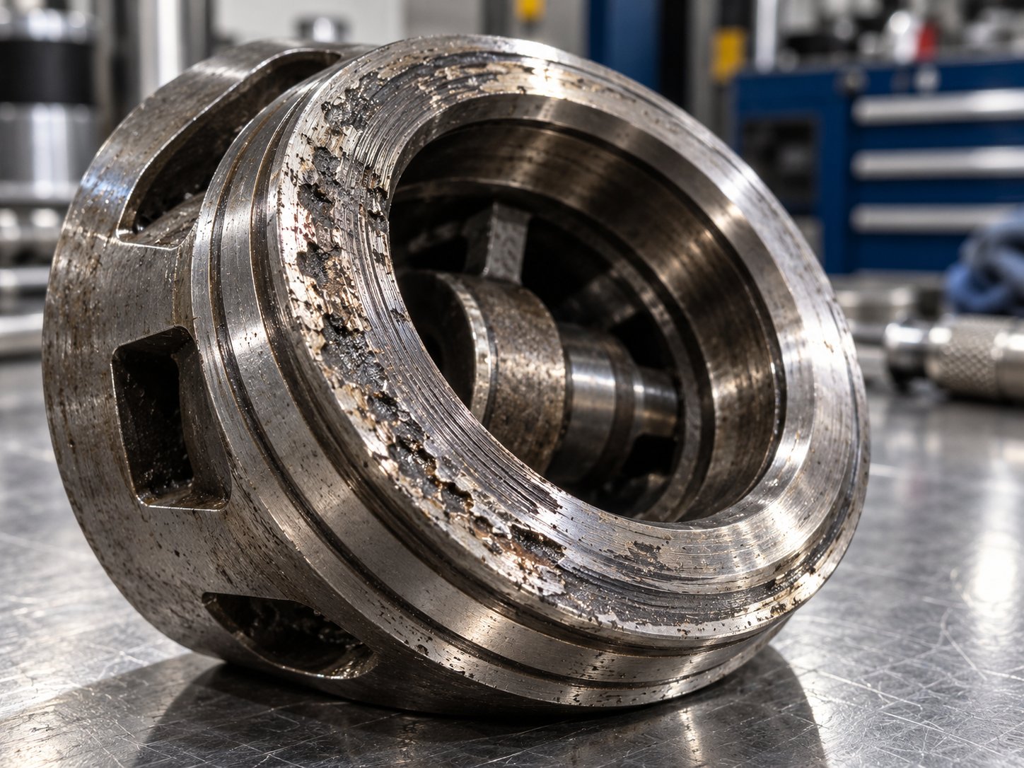
A worn check ring cannot close cleanly. As the seating surfaces erode — through abrasion from filled resins, corrosion from aggressive polymers, or simple metal fatigue over thousands of cycles — a gap develops between the ring and its mating seat. Melt slips backward through that gap during injection and hold. The result is twofold: the screw creeps further forward than it should because the melt pad in front of it is shrinking, and the volume of plastic actually delivered to the cavity drops.
This is where injection molding cushion definition meets real-world screw position and nozzle distance behavior. If you are trending cushion shot-to-shot and notice a gradual downward drift — the screw reaching a smaller residual distance from the nozzle over successive cycles — a leaking check ring is the prime suspect. The Asaclean troubleshooting guide identifies this pattern clearly: an improperly functioning non-return valve allows material to slip past it, causing the screw to encroach forward and limiting control over consistent cavity packing.
The progression is predictable. Early-stage check ring wear shows up as a slight widening of the shot-to-shot cushion scatter band — maybe an extra 0.2 mm of variation that would not trigger a cushion alarm injection molding controller is set to detect. Intermediate wear produces noticeable cushion drift across a shift, often accompanied by subtle part weight changes. Advanced wear makes the cushion erratic from cycle to cycle, because the ring seats properly on some shots (when melt pressure happens to press it flat) but fails to seat on others. At this stage, short shots and visible sink marks typically appear, and shot-weight variation becomes one of the most common symptoms flagged during quality checks.
A check-ring repeatability test is the definitive diagnostic. The procedure involves injecting against a blocked or closed mold and observing whether the screw holds its position or drifts forward under held pressure — forward drift confirms melt is leaking past the valve. This test should be performed by an experienced technician under safe conditions, as it involves hot plastic and high hydraulic pressures.
Barrel and Screw Wear Patterns That Affect Cushion
The check ring gets most of the attention, but it does not work in isolation. The barrel bore and screw flights form the second line of defense against melt leakage. During recovery, the screw's rotating flights convey plastic forward through the heated barrel. The clearance between the outer edge of the flight and the inner wall of the barrel is intentionally tight — typically a few hundredths of a millimeter on a new assembly. That tight fit ensures efficient forward conveyance and prevents excessive melt from leaking backward over the flights.
As both surfaces wear, that radial clearance grows. More melt can flow backward across the flights during injection, effectively bypassing the check ring entirely. Even a perfectly functioning non-return valve cannot compensate for a barrel bore that has enlarged beyond specification — the leakage path is upstream of the valve. The Daya Machinery replacement guide highlights a critical maintenance principle here: replacing only the check ring while continuing to use a severely worn barrel can quickly damage the new ring and fail to restore production performance.
Screw flight wear typically concentrates in the metering section and other high-pressure zones where the melt exerts the greatest outward force against the flights. Glass-fiber-reinforced resins, mineral-filled compounds, and recycled materials containing contaminants accelerate this wear dramatically. Visible signs include reduced flight outer diameter, uneven wear across the screw length, pitting, and coating separation. But here is the catch — you cannot see these signs without pulling the screw. That is why cushion trending serves as a surrogate indicator. A gradually widening cushion variation band, combined with increasing plasticizing time, often points to progressive screw-to-barrel clearance growth long before anyone schedules a screw pull.
Barrel bore wear is measured with internal gauges at multiple positions along the barrel length. Comparing the measured bore diameter against the original specification — and against the current screw flight diameter — reveals the actual operating clearance. There is no single universal replacement limit; the acceptable clearance depends on screw diameter, machine design, processed material, and application tolerance requirements. What matters for cushion stability is whether the clearance has grown enough to create a meaningful backflow path during injection.
Nozzle Seal Integrity and Its Overlooked Role
The nozzle tip sits at the very front of the barrel assembly, forming the final seal between the injection unit and the mold's sprue bushing. A worn nozzle tip or damaged seat allows melt to leak forward — drooling between shots — and can also permit backflow if the nozzle does not seat firmly against the sprue bushing during injection. Either scenario destabilizes the melt volume available for packing.
Nozzle drooling is sometimes dismissed as a cosmetic nuisance — a string of plastic hanging from the tip between cycles. But that drooled material represents volume lost from the shot. As the Wanplas nozzle drooling analysis explains, a drooling nozzle loses a small amount of material between shots, so the actual injected weight varies cycle to cycle, defeating weight-based process monitoring and pushing fill, pack, and dimensions out of tolerance. That weight variation feeds directly into cushion instability, because the effective melt charge available at the start of each injection stroke is no longer consistent.
A mismatched nozzle radius — where the nozzle tip radius is larger than the sprue bushing entry radius — creates an incomplete seal that no temperature adjustment can fix. This geometric cause requires physically matching the nozzle and bushing radii. Worn nozzle orifices that have enlarged through erosion similarly reduce the resistance to melt flow, making the front end more prone to leakage under residual pressure.
When mechanical inspection confirms that a check ring, screw tip, nozzle, or other wear component has degraded beyond serviceable limits, the resolution is straightforward: replace the worn part. The practical challenge for many maintenance teams is sourcing compatible replacement components — especially for older machines or non-standard configurations where original manufacturer parts may be expensive or have long lead times. Suppliers like NANHAIYA offer replacement check rings, non-return valves, screw tips, injection nozzles, and thermocouples for a range of injection molding machines, and can assess part compatibility by reviewing machine details, drawings, worn samples, photos, and dimensions before quoting. Building a relationship with a reliable spare parts source before an emergency failure hits is far less costly than scrambling for components while a press sits idle and cushion variation turns into scrap.
Mechanical wear, though, is only one branch of the diagnostic tree. A perfectly sealed barrel assembly can still produce unstable cushion readings if the thermal environment or the feedstock itself is shifting — forces that act on melt viscosity rather than melt containment, and that demand an entirely different set of investigative tools.
How Thermal Shifts and Material Changes Destabilize Cushion
A barrel assembly in perfect mechanical condition — tight check ring, clean bore, pristine screw flights — can still produce erratic cushion readings. How? Because the definition of cushion in injection molding depends not only on where the melt is sealed, but on how that melt behaves under pressure. Change its viscosity even slightly, and you change how far the screw pushes forward, how much melt slips past the check ring, and how effectively packing pressure reaches the cavity. Thermal and material factors are the invisible hands that move viscosity around without anyone touching a parameter on the controller.
Barrel Temperature Profile and Cushion Stability
Your barrel is not a single-temperature oven. It is divided into multiple heating zones — typically rear, center, and front — each with its own heater band, thermocouple, and temperature controller. The purpose of that zoned arrangement is to create a deliberate thermal gradient that progressively melts the resin as the screw conveys it forward. When every zone holds its setpoint accurately, the melt arriving at the front of the screw has a predictable viscosity, and the screw pushes against a consistent resistance every shot. Cushion position in injection molding stays where you expect it.
Disrupt that gradient, and the dominoes start falling. Imagine the center zone drifts 10 degrees below its setpoint because a heater band is partially failing. The resin passing through that zone absorbs less heat, arrives at the metering section slightly more viscous than normal, and requires more screw torque and pressure to push forward. The screw may not reach its full recovery position in the allotted time, or the higher-viscosity melt may resist compression during injection differently than a properly heated charge. Either way, the cushion reading shifts — sometimes gradually enough that no alarm fires, but consistently enough that part weight and dimensions start to wander.
The reverse scenario is equally problematic. An overheating zone — caused by a stuck relay, a controller fault, or a thermocouple reading artificially low — delivers a thinner, less viscous melt. That lower-viscosity melt leaks more easily past the check ring during injection, compounding any existing mechanical clearance. As CKMOLD's temperature profile guide emphasizes, barrel zone setpoints alone are not the melt temperature — screw speed, back pressure, residence time, and shear all contribute additional heat that the controller does not directly measure. This means the actual melt condition can deviate from what the screen displays, especially when supporting thermal hardware degrades.
Three specific thermal failure modes deserve attention:
- Heater band degradation: Heater bands do not always fail in a dramatic, total-loss fashion. More commonly, a band develops a partial short or a high-resistance section. It still produces heat, but less than the controller expects. The PID loop compensates by keeping the heater on longer, which can overshoot during low-demand periods and undershoot during high-demand periods (such as fast recovery). The result is temperature oscillation within the zone — not a flat deviation, but a cycling instability that creates shot-to-shot viscosity fluctuation.
- Thermocouple drift: Thermocouples age. Their output can drift over thousands of hours of operation, reporting a temperature that is slightly higher or lower than reality. A thermocouple reading 5 degrees high tells the controller the zone is hotter than it actually is, causing the controller to reduce heater output. The zone runs cold, viscosity rises, and cushion position shifts — all while the controller display shows the "correct" setpoint. Periodic calibration verification catches this before it silently erodes process stability.
- Inadequate soak time: After startup or an extended pause, the barrel zones may reach their setpoint temperatures well before the entire mass of steel — and the resin inside it — reaches thermal equilibrium. A controller display showing all zones at setpoint does not guarantee the melt is at a uniform, stable temperature throughout the barrel. Injecting before the system has truly soaked through produces the first several shots with inconsistent viscosity, and the cushion time in injection molding during those early cycles can look dramatically different from steady-state production. As industry guidance recommends, startup soak time, first-good-part rules, and pause/restart procedures should be defined for each specific grade rather than assumed from generic timelines.
The takeaway for cushion stability is direct: thermal hardware verification — resistance testing on heater bands, calibration checks on thermocouples, and disciplined soak time protocols — belongs on every preventive maintenance schedule. A perfectly tuned process sheet means nothing if the hardware delivering that thermal profile is quietly drifting out of specification.
Amorphous vs Semi-Crystalline Resin Behavior
Not all plastics respond to temperature the same way, and that difference has a meaningful impact on how sensitive your cushion is to thermal and processing fluctuations. The distinction comes down to molecular structure — specifically, whether the resin is amorphous or semi-crystalline.
Amorphous polymers like ABS, polycarbonate (PC), and polystyrene have a random, jumbled molecular arrangement. They soften gradually over a broad temperature range, transitioning from solid to rubbery to flowable without a distinct melting point. This gradual transition means their viscosity changes relatively smoothly with temperature. From a cushion perspective, amorphous resins are somewhat more forgiving — a few degrees of barrel temperature variation produces a proportional, predictable viscosity shift rather than a dramatic one.
Semi-crystalline polymers — polypropylene (PP), nylon (PA), POM, PBT, PET — behave very differently. Their ordered crystalline molecular structure gives them a sharp melting point. Below that point they remain solid; above it they transition rapidly into a low-viscosity liquid. This sharp transition means that small temperature changes near the melting point can produce large viscosity swings. If your barrel temperature drifts even modestly in a zone processing a semi-crystalline resin, the melt viscosity can shift enough to noticeably alter screw dynamics and cushion position.
The practical implication? Semi-crystalline resins demand tighter thermal control to maintain stable cushion readings. Their sensitivity to temperature makes them less tolerant of heater band degradation, thermocouple drift, and insufficient soak time. Amorphous resins are more forgiving of thermal noise but are not immune — especially when running near the lower or upper edge of their processing window, where viscosity sensitivity increases.
This difference also shows up during the hold phase. Semi-crystalline materials shrink significantly more than amorphous ones as they crystallize in the mold, which means they draw more material through the gate during packing. Any viscosity inconsistency in the cushion affects how efficiently that packing flow occurs, amplifying the downstream quality impact for semi-crystalline parts compared to amorphous ones.
Moisture Content and Regrind Ratio Effects
Thermal hardware is only half of the viscosity equation. The material itself can introduce variation that no barrel profile can compensate for — and these material-side causes are among the most overlooked contributors to injection molding cushion variation.
Hygroscopic resins — nylon, PET, polycarbonate, ABS, and many engineering grades — absorb moisture from the air. That absorbed water acts as a plasticizer during processing, lowering melt viscosity and altering flow behavior. If your drying process is inconsistent — dryer cycling on and off, desiccant not regenerated on schedule, hopper lids left open during material changes — the moisture content of the resin entering the barrel fluctuates from one batch of pellets to the next. The screw sees a melt that is thinner on some shots and thicker on others, and the cushion reading reflects that inconsistency directly.
Moisture also triggers hydrolysis in condensation polymers like nylon and PET, breaking polymer chains and permanently reducing molecular weight. That degraded material has a lower viscosity than properly dried resin, meaning the screw pushes it forward more easily and the check ring has a harder time containing it during hold. The cushion drops, the packing suffers, and part weight falls — all from a dryer that was not doing its job consistently. As Hunter Plastics notes, if you are running moisture-sensitive materials, your dryer's performance matters just as much as your barrel settings when investigating weight and cushion drift.
Beyond moisture, several other material-side variables create the same type of viscosity instability that shows up as cushion variation:
- Lot-to-lot viscosity variation: Resin manufacturers produce material within a specified melt flow index (MFI) range, not at a single exact value. A lot at the low end of that range flows differently than one at the high end. When a new lot enters production, cushion may shift to a new baseline without any process change.
- Regrind percentage changes: Regrind has different bulk density, particle size distribution, and thermal history than virgin pellets. Increasing the regrind ratio alters how efficiently the screw conveys and melts material, changes the effective melt viscosity, and shifts cushion position. Even small, undocumented changes — an operator adding a handful more regrind than the recipe specifies — can produce measurable effects.
- Filler loading shifts: Glass fiber, mineral fillers, and carbon fiber significantly increase melt viscosity and abrasiveness. A batch with slightly higher filler content creates more resistance during injection, changes screw dynamics, and accelerates wear on the check ring, barrel, and screw flights. The cushion impact is both immediate (viscosity change) and cumulative (accelerated mechanical degradation).
- Additive package changes: Colorants, UV stabilizers, flame retardants, and processing aids all modify melt behavior. A color change that introduces a different pigment carrier can shift viscosity enough to move cushion — even when the base resin is identical.
The common thread across all of these material variables is that they change what the screw "sees" without changing what the controller displays. Your setpoints stay the same, your cycle parameters stay the same, but the melt responds differently because its fundamental properties have shifted. That is precisely why process troubleshooting guidance consistently recommends checking resin lot, moisture, regrind, and material feeding as a standard early step when cushion or part weight begins to drift.
Thermal and material causes share an important characteristic: they both act on viscosity. But they reach the cushion through different paths — one through hardware degradation, the other through feedstock inconsistency. The machine itself adds yet another layer to this picture. How different drive types — hydraulic, electric, and hybrid — handle screw positioning under pressure has a direct bearing on how tightly cushion can be controlled, even when thermal and material conditions are perfectly stable.
Machine Type and Back Pressure Effects on Cushion Consistency
You could have a perfectly sealed check ring, flawless barrel temperatures, and bone-dry resin — and still watch your cushion readings bounce around if the machine itself cannot position the screw accurately. The importance of cushion in injection molding ultimately rests on how repeatably the screw reaches and holds its end-of-hold position, and that repeatability is governed by the drive system pushing the screw forward. Hydraulic, all-electric, and hybrid machines handle this job in fundamentally different ways, with measurable consequences for cushion stability.
Hydraulic vs Electric vs Hybrid Cushion Repeatability
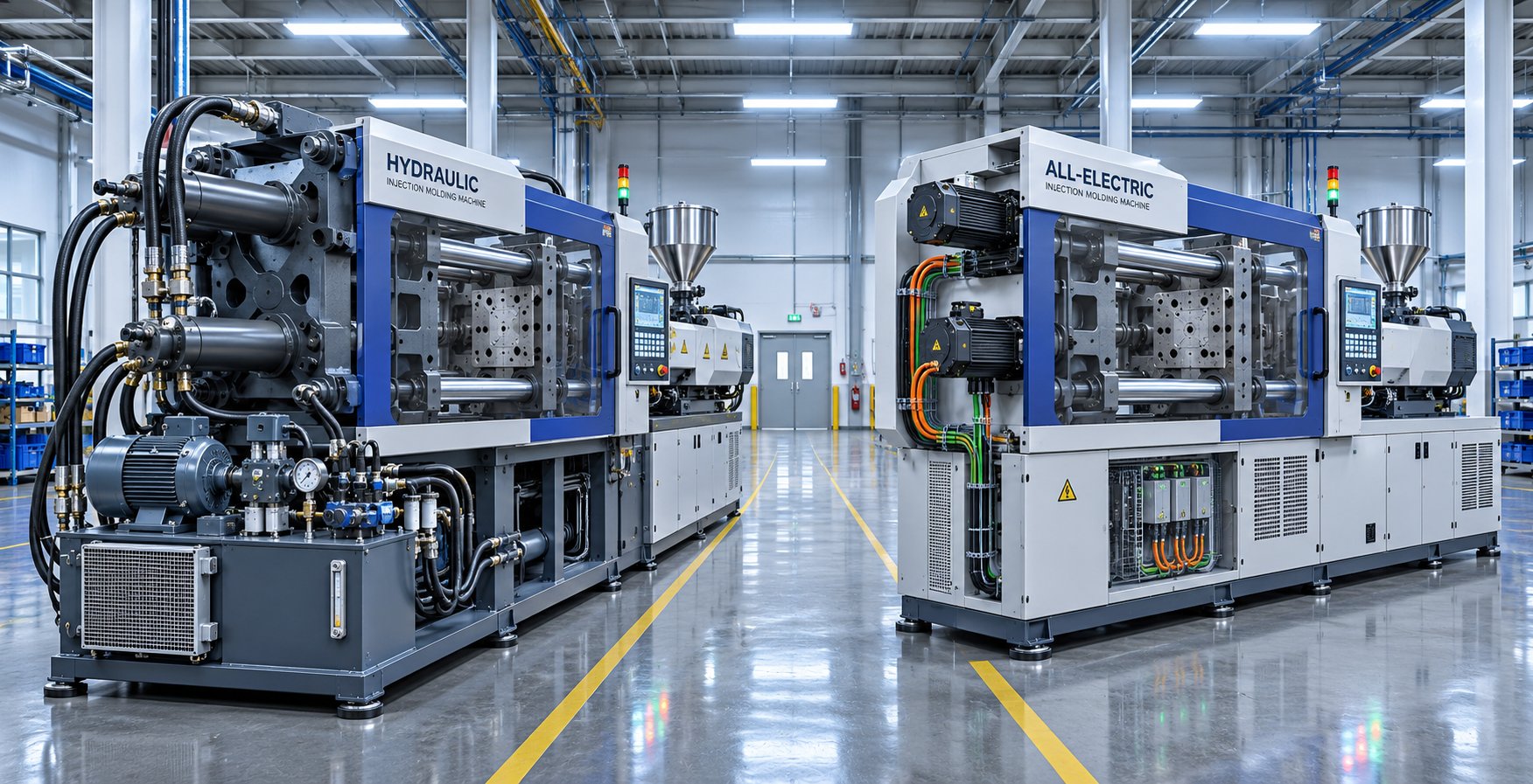
Hydraulic injection molding machines use pressurized oil acting on a piston to drive the screw forward during injection and hold. Sounds simple enough, but several variables introduce positional uncertainty. Oil viscosity changes with temperature — cold oil at startup behaves differently from oil that has been circulating for six hours. Proportional valves that regulate flow to the injection cylinder have finite response times, meaning the screw does not stop instantaneously when the controller commands a position change. And the compressibility of hydraulic fluid itself creates a "springiness" in the system that all-electric drives simply do not have.
A study comparing machine-specific behavior across two hydraulic and one electric Arburg injection molding machines demonstrated these differences quantitatively. The researchers found that a basic hydraulic machine (single-chamber injection control with a speed-controlled radial piston pump) showed the highest overrun of the switchover point — meaning the screw consistently traveled past its intended stop position. That overrun varied with injection speed and barrel temperature settings, making its effect on cushion position unpredictable across different operating points.
The second hydraulic machine in the study used a more advanced dual-chamber positioning system with servo-control valves and a hydraulic accumulator. This clamped hydraulic design delivered significantly better screw position accuracy — approaching the switchover volume with far less overrun and showing much higher robustness against disturbance variables like material changes and temperature shifts. The takeaway? Not all hydraulic machines behave the same. Drive architecture and control strategy matter enormously for cushion repeatability, even within the same drive category.
The all-electric machine used servo motors for screw drive and ring membrane sensors for position measurement. It metered the set dosing volume with near-perfect precision — a clear advantage during screw recovery. However, the servo motor exhibited limited deceleration during braking at the end of injection, causing some overrun of the switchover point at higher flow rates. In other words, electric machines excel at positioning accuracy during recovery but can still show lag-related variability during fast injection transitions.
Hybrid machines combine electric screw rotation with hydraulic injection, or vice versa. They typically fall between pure hydraulic and pure electric systems in positional accuracy. The injection molding cushion definition — screw position at end of hold relative to nozzle distance — depends on whichever drive system controls the injection and hold phases, so a hybrid with electric injection benefits from servo precision during the critical packing stage.
The table below summarizes these differences as a practical reference for processors evaluating how their machine type influences cushion behavior:
| Drive Type | Screw Position Accuracy | Cushion Repeatability Advantage | Typical Application Fit |
|---|---|---|---|
| Hydraulic (basic single-chamber) | Lower — influenced by oil temperature, valve response lag, and single-direction pressure control | Least repeatable; overrun varies with flow rate and temperature settings | General-purpose molding; non-critical cushion tolerance applications |
| Hydraulic (advanced position-controlled) | Moderate to high — dual-chamber servo-valve systems achieve tight positional control | Good repeatability; robust against material and temperature disturbances | Mid-precision parts; automotive and industrial applications |
| All-Electric (servo-driven) | Highest during recovery/metering; some braking lag at high injection speeds | Excellent shot-to-shot consistency; minimal environmental sensitivity | Medical, optical, and precision applications requiring tight cushion windows |
| Hybrid (mixed drive) | Depends on which drive handles injection/hold — electric injection offers better precision | Intermediate; benefits of electric precision where applied to injection axis | Versatile — balances precision with hydraulic clamping force for larger molds |
If you are running a high cushion position in plastic injection molding and struggling with shot-to-shot scatter, your machine's drive type may be contributing more to the problem than you realize — especially on an older hydraulic press with worn proportional valves and aging hydraulic seals. The same process sheet transferred from an electric machine to a basic hydraulic press can yield visibly different cushion behavior without a single parameter change.
Back Pressure Influence on Melt Homogeneity and Cushion
Back pressure acts during a completely different phase of the cycle — screw recovery — but its fingerprints show up in cushion stability on the very next shot. When the screw rotates to meter new material, back pressure is the hydraulic or servo-controlled resistance applied against the screw's rearward movement. It forces the melt to compress as it accumulates in front of the screw tip, squeezing out trapped air and producing a denser, more uniform melt charge.
Why does this matter for cushion? Because melt density directly determines how the screw behaves during injection and hold. A well-compacted melt charge compresses predictably under injection pressure, transmitting force efficiently through the nozzle and into the mold. A loosely compacted charge — one metered with insufficient back pressure — contains micro-voids and density gradients. When the screw pushes forward against that inconsistent melt, the compression behavior changes from shot to shot. Some shots pack tightly, others absorb more of the injection energy just compressing trapped gas, and the cushion reading at end of hold reflects that inconsistency.
As Suhas Kulkarni of Fimmtech explains, back pressure helps compress the softened, semi-molten pellets and squeeze off all the air or gases from between them. More importantly, it compresses the melt to the same consistency — the same melt density — every single shot. Consistent melt density means consistent fill, which improves shot-to-shot repeatability and overall process capability.
There is an optimum, though. Kulkarni's data-driven optimization procedure reveals that as back pressure increases from a low starting value, the shot-to-shot weight range narrows — confirming better melt homogeneity. But beyond a certain point, the range increases again. The explanation? Excessively high back pressure causes the melt to slip on the screw flights rather than conveying forward smoothly. That slippage introduces the very inconsistency you were trying to eliminate. The optimal back pressure is the value where the shot-to-shot weight range reaches its minimum — a point that varies by material, screw design, and machine type.
Back pressure drift or instability during production is a subtler but equally damaging issue. On hydraulic machines, back pressure is controlled through pressure-relief valves or proportional valves that regulate hydraulic flow during screw rotation. If those valves are sticking, worn, or responding sluggishly, the actual back pressure during recovery fluctuates even though the setpoint has not changed. Each shot meters under slightly different compaction conditions, and the resulting cushion variation appears random — mimicking the erratic scatter pattern that might otherwise point you toward a check ring problem. On electric machines, servo control of back pressure is typically more precise and less susceptible to drift, adding yet another repeatability advantage to the electric drive column.
Decompression Settings and Their Hidden Impact
Decompression — also called suck-back — is the brief rearward linear movement of the screw after recovery completes (post-rotation decompression) or before recovery begins (pre-rotation decompression). Its primary purpose is to relieve residual melt pressure at the nozzle tip, reducing drool between shots and easing stress on valve gate components. Most modern controllers let you set both pre-rotate and post-rotate decompression independently. Used correctly, decompression stabilizes your process. Used incorrectly, it becomes a hidden source of cushion instability.
Here is the mechanism. When the screw pulls back after rotation without turning, it creates a low-pressure zone in front of the screw tip. That decompression does not add more plastic to the shot — the screw is not rotating, so no material is being conveyed forward. But it does increase the total distance the screw must travel during the next injection stroke to reach the transfer point. If your decompression setting is inconsistent — the screw retracts a different amount each cycle due to valve lag on a hydraulic machine or a poorly tuned servo profile — the effective starting position of the screw varies, and your injection molding machine may show no cushion or erratic cushion even though shot size has not changed.
As Robert Gattshall details in Plastics Technology, post-rotation decompression can also introduce air into the barrel. If that air does not escape before the next injection stroke, it essentially helps push more of the shot volume into the mold — altering the effective pack even though the volume of plastic has not changed. The cushion may appear stable on the position readout while actual packing conditions fluctuate because of trapped air compressing and expanding unpredictably.
Pre-rotation decompression carries a different risk. By creating space between the screw tip and the cushion before recovery begins, it delays the build-up of plastic pressure during the early portion of screw rotation. The screw effectively works as an extruder — pushing material forward without retracting — until that space fills. This can increase the actual volume of material in the shot, shifting cushion downward and potentially overpacking the part.
Gattshall also highlights a practical benefit of controlled decompression: setting post-rotation suck-back slightly higher than the throw of the check ring helps the non-return valve seat consistently before injection begins. Many experienced processors adopt this technique specifically to improve cushion repeatability by ensuring the check ring closes cleanly every cycle. The key word, however, is "controlled." Excessive or erratic decompression — especially on hydraulic machines where the linear retraction speed and distance may vary with oil temperature — introduces more variation than it solves.
Machine type, back pressure optimization, and decompression tuning all shape how consistently the screw positions itself cycle after cycle. These are the controllable inputs. The real power, though, comes from monitoring what actually happens — trending cushion over time and reading the patterns it reveals — to catch developing problems before they turn into scrap bins full of rejected parts.
Using Cushion Variation as an Early Warning Diagnostic Tool
Up to this point, the discussion has focused on what causes an unstable cushion in injection molding — worn components, thermal drift, material shifts, and machine-level positioning differences. All of those factors matter. But there is a perspective shift worth making: cushion variation is not just a problem to solve. It is one of the most sensitive, real-time diagnostic signals your injection molding machine already generates. The question is whether you are reading it.
Every cycle, the machine records where the screw sits at the end of hold. That single data point, tracked over hundreds or thousands of shots, becomes a living health report for the process. It reflects the combined state of every system — mechanical, thermal, material, and process settings — compressed into one measurable value. Learning to read the patterns in that data turns a reactive troubleshooting exercise into a proactive early-warning system that catches developing issues before they ever reach the sorting bin.
What Screw Position Trending Reveals Over Time
Imagine plotting your end-of-hold screw position on a simple time-series chart — one dot per shot, running left to right across a shift, a day, a week. When the process is stable, those dots cluster tightly around a center line with only minor scatter. That tight band is what a healthy process looks like. The moment something changes in the system, the pattern shifts — and the shape of that shift tells you where to look.
Real-time trending of cushion position at the end of the pack/hold phase is among the earliest indicators of process degradation. Statistical process control (SPC) applied to cushion data can reveal check ring problems two to four weeks before they begin affecting part quality. That is not a small window — it is the difference between a planned maintenance pull during a scheduled downtime and an emergency screw extraction while production waits.
The reason for cushion variation in injection molding almost always leaves a signature in the trend data. Here are the four most common patterns and what each one points toward:
- Gradual drift in one direction — The cushion value slowly creeps lower (screw advancing further forward) or the shot-to-shot scatter band widens progressively over days or weeks. This is the hallmark of mechanical wear. Check ring sealing surfaces erode incrementally, allowing slightly more backflow each shift. Barrel bore enlargement follows the same slow trajectory. If you are watching the trend, you will see this pattern develop long before part quality visibly suffers.
- Sudden step change — The cushion jumps to a distinctly new baseline and stays there. Something discrete changed: a new resin lot with a different melt flow index entered the hopper, an operator adjusted shot size or back pressure during a shift handoff, or a heater band failed completely in one zone. Step changes are usually the easiest to diagnose because the timing correlates with a specific, identifiable event.
- Erratic, random scatter — No clear trend or direction, just wide, unpredictable shot-to-shot swings. This is the most frustrating pattern to troubleshoot because it mimics randomness. The usual culprits are intermittent mechanical failures — a check ring that seats cleanly on some cycles but cocks or hangs open on others — or moisture content that fluctuates as a dryer cycles inconsistently. Both produce variation that appears and disappears without warning.
- Startup-related instability that settles over time — Cushion readings are erratic or offset for the first 15 to 30 minutes of a run, then gradually converge to a stable value. This points directly to thermal causes: insufficient barrel soak time, hydraulic oil warming up and changing viscosity on a hydraulic press, or heater bands that overshoot and oscillate before PID control stabilizes them.
None of these patterns by themselves name a specific failed component. They narrow the search. A gradual drift sends you to the mechanical branch of the diagnostic framework. A step change sends you to material records and process logs. Erratic scatter triggers a check ring repeatability test and a dryer performance audit. Startup instability prompts a review of soak time protocols and thermal hardware health. The trend is the compass — verification follows.
Reading the Injection Cycle Screw Position Curve
Trending cushion across many shots reveals long-term process behavior. But zooming in on a single cycle — plotting screw position against time for one injection stroke — reveals the mechanics of how that cushion value is created. Understanding this curve is essential for anyone trying to figure out how to fix minimum cushion in an injection mold or diagnose why cushion is disappearing mid-run.
Here is what you would see on a typical position-versus-time trace. The screw starts at its retracted position — the shot size setpoint. When injection begins, the screw drives forward rapidly under velocity control, pushing the melt charge through the nozzle, runner, and into the cavity. The position drops steeply on the chart as the screw moves toward the nozzle. This is the fill phase, and speed is the controlled variable.
At the switchover point, the machine transitions from velocity control to pressure control. The screw's forward motion decelerates sharply — you will see the steep drop flatten into a much gentler slope. This is the pack-and-hold phase. The screw continues pressing forward, but now at a controlled pressure rather than a controlled speed, compensating for the volumetric shrinkage of cooling plastic inside the cavity. The rate of forward movement slows progressively as the gate freezes and less material can flow into the mold.
When hold time expires, the pressure command drops to zero (or to back pressure level as recovery begins). The screw position at that exact moment — the point where the hold-phase curve terminates — is your cushion reading. Everything on the curve before it shapes what that final value will be. An unusually steep fill slope might indicate lower melt viscosity (hotter melt or wetter material). An extended, slow creep during hold might suggest the gate is staying open longer than expected (hotter mold, larger gate). A screw that reaches the same position during fill but then drifts further forward during hold — compared to previous cycles — is showing you backflow past the check ring in real time.
Process engineers who overlay multiple cycles on the same chart can spot these subtle shifts visually. When the hold-phase portion of the curve starts spreading out — some cycles showing the screw drifting further, others holding steady — you are looking at the injection cycle's fingerprint telling you that sealing consistency is deteriorating.
Setting Meaningful Cushion Alarm Limits
Most machine controllers allow you to set high and low alarm thresholds for cushion position. The temptation is to pick round numbers — say, 2 mm and 8 mm — based on general guidelines or gut feel. The problem with arbitrary limits is that they are either too loose to catch real problems or too tight to avoid nuisance alarms. Either way, the alarm loses credibility with operators, and meaningful signals get ignored alongside false ones.
A far more effective approach ties alarm limits to your own validated process data. As Aprios details in their process control methodology, control limits are calculated from the process average and standard deviation — typically set at three standard deviations above and below the mean. This range captures nearly all normal variation. A value falling outside it signals that something in the process has genuinely changed, not just fluctuated within its normal band.
The distinction between control limits and specification limits matters here. Specification limits define what is acceptable for the customer — the part drawing tolerance. Control limits describe how your specific process actually behaves when it is stable. When the process stays within its control limits, it naturally stays within specification. But when a cushion reading crosses a control limit — even if parts still look acceptable — the process is no longer behaving as validated. That early signal is the entire point.
Many operations benefit from a two-tier alarm structure. A pre-alarm triggers at an early warning level — often around two standard deviations from the mean. This gives the operator or technician a heads-up to check conditions: Has the material lot changed? Is a barrel zone drifting? Is recovery time creeping up? A hard alarm triggers at the full three-sigma control limit. At that point, parts should be contained or segregated until the root cause is identified and corrected.
This two-level approach balances responsiveness with stability. The pre-alarm prevents overreaction to normal process noise while still flagging meaningful drift early. The hard alarm provides a clear stop-and-investigate boundary that keeps suspect parts from reaching the customer. Both levels should be established during process validation — using data from a stable, qualified run — and embedded directly into the machine controller or monitoring system so they function automatically, every cycle, every shift.
The value of this approach compounds over time. Alarm events become data points themselves. A machine that triggers pre-alarms every Tuesday afternoon might be telling you something about ambient temperature shifts or material delivery schedules. A press that consistently hits hard alarms after a specific number of cycles is mapping its own mechanical wear curve. That historical record transforms cushion monitoring from a cycle-by-cycle check into a long-term predictive maintenance tool — one that tells you not just what is happening now, but what is likely to happen next.
Of course, monitoring and alarms only catch problems. They do not prevent them. The real payoff comes from combining diagnostic trending with a structured preventive maintenance program — one that systematically addresses each root cause category before it ever triggers an alarm in the first place.
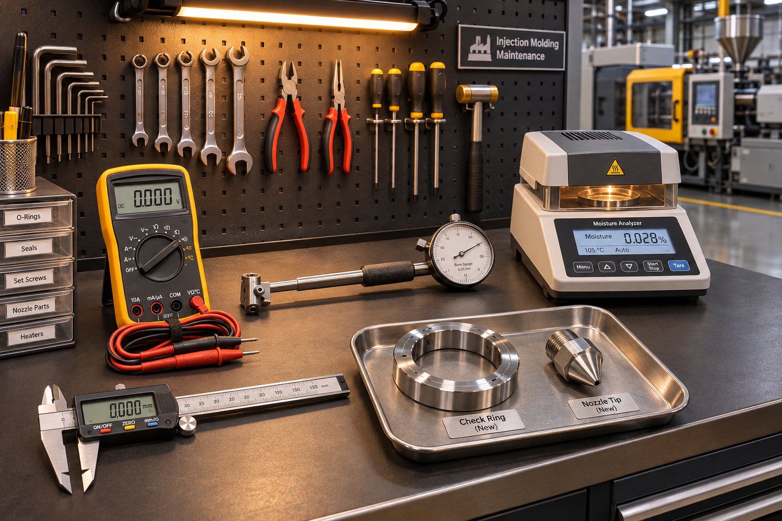
Preventive Maintenance Strategies That Stabilize Cushion
Alarms tell you something has already changed. Trend charts show you something is changing. But neither one prevents the change from happening in the first place. The most effective way to keep injection molding cushion variation within acceptable limits is to systematically maintain the four systems that control it — mechanical, thermal, material, and process — before any single component degrades enough to push cushion outside its validated window.
The root cause framework introduced earlier in this article is not just a troubleshooting map. It is also a preventive maintenance blueprint. Each category has its own set of inspectable, measurable, and replaceable elements. Addressing them on a disciplined schedule — prioritized by their impact on cushion stability — converts cushion monitoring from a reactive alarm system into a proactive quality assurance strategy. Here is an injection molding cushion maintenance schedule organized by impact and urgency.
- Perform a check ring repeatability test at a defined cycle interval (many operations use every 50,000 to 100,000 shots, adjusted for resin abrasiveness). This single test is the fastest way to confirm or rule out the leading mechanical cause of cushion drift.
- Measure and record cushion position statistics weekly. Compare the current shot-to-shot mean and range against your validated baseline. A widening range — even within alarm limits — is your earliest warning signal.
- Verify barrel zone temperatures against setpoints at the start of every shift. Look for zones that overshoot, oscillate, or take longer than expected to reach setpoint. These patterns indicate thermal hardware degradation.
- Confirm incoming material moisture levels before each new lot enters the hopper. For hygroscopic resins, a handheld or inline moisture analyzer provides a direct, real-time check that the dryer is performing correctly.
- Audit back pressure and decompression settings against the validated process sheet at least once per shift. Verify that the actual gauge reading matches the setpoint — not just that the controller displays the right number.
- Inspect the nozzle tip and seat during every mold change or at a defined cycle count. Look for erosion, drool marks, and fit against the sprue bushing.
- Pull and inspect the screw assembly annually (or more frequently for abrasive or filled resins). Measure check ring seating surfaces, screw flight outer diameter, and barrel bore inner diameter against original specifications.
- Test heater band resistance and thermocouple calibration on a semi-annual schedule or whenever a zone shows temperature instability.
- Review regrind ratio controls and lot-change documentation quarterly. Confirm that material blending procedures match validated recipes and that lot transitions are logged with timestamps.
This sequence moves from the highest-frequency, highest-impact checks (check ring function, cushion trending) through thermal and material verification, down to the longer-interval mechanical inspections that require pulling the screw. The logic is simple: catch fast-developing problems with frequent checks, and catch slow-developing problems with periodic deeper inspections.
Mechanical Inspection and Replacement Schedules
Mechanical wear is gradual, invisible from the outside, and responsible for the majority of progressive cushion drift. That makes it the most important — and most frequently neglected — maintenance category. A structured inspection schedule prevents the slow creep of check ring erosion and barrel clearance growth from turning into emergency downtime.
The check ring repeatability test, described earlier in the troubleshooting section, belongs on a recurring schedule — not just as a diagnostic response to an existing problem. Many experienced molders tie this test to a cycle count threshold. Operations running unfilled commodity resins on standard tooling may test every 100,000 shots. Operations running glass-filled nylon or mineral-filled PBT — materials that aggressively abrade sealing surfaces — may test every 25,000 to 50,000 shots. The test itself takes only a few minutes and provides a definitive pass-or-fail answer on check ring sealing integrity.
The annual screw pull is the deeper inspection event. As Plastics Technology's preventive maintenance guide recommends, the screw should be pulled once a year to inspect the shank, flights, and barrel inner diameter against the screw manufacturer's recommended dimensional requirements. During this inspection, measure the check ring seating surfaces for wear grooves, pitting, and roundness. Measure screw flight outer diameter at multiple points along the length — especially in the metering section where wear concentrates. Use a bore gauge to measure the barrel inner diameter at several positions and compare against the original specification. Document every measurement so you can track the rate of wear over successive inspections and predict when replacement will be needed.
When measurements show components have crossed their serviceable limits, replacement becomes the only path to restoring cushion stability. The practical challenge is having the right parts available when you need them — not scrambling to source a check ring or screw tip while a press sits idle. Building a spare parts inventory for high-wear items like check rings, non-return valves, screw tips, and nozzle assemblies is a core element of preventing cushion drift in injection molding operations. Suppliers such as NANHAIYA supply replacement check rings, non-return valves, screw tips, injection nozzles, and thermocouples, and evaluate part compatibility by reviewing machine details, worn samples, drawings, and dimensional data before quoting — a process that fits naturally into a planned maintenance workflow where you send worn parts for assessment well before the next scheduled replacement date.
Nozzle tips deserve their own line item on the inspection checklist. Unlike the screw and barrel, nozzle tips can be inspected and replaced during mold changes without a full screw pull. Check the orifice for enlargement, the seating surface for erosion, and the radius for damage that could prevent a proper seal against the sprue bushing. A five-minute nozzle inspection during every mold swap costs almost nothing and catches a wear point that can quietly destabilize cushion for weeks before anyone connects the drool on the platen to the weight scatter on the scale.
Thermal System Verification Protocols
Thermal hardware fails in subtle ways. A heater band that is partially degraded still produces heat — just not enough, or not evenly. A drifting thermocouple still reports a temperature — just not the right one. These partial failures are harder to detect than a dead component, and they create exactly the kind of slow viscosity drift that shows up as gradually widening cushion scatter.
Heater band performance should be verified through resistance testing rather than simply checking whether the zone reaches setpoint. As the Daya Machinery heater band guide explains, measuring continuity of a band does not always reveal a poorly performing unit — a band can show continuity while delivering insufficient or uneven heat output. Use the formula R = V squared / P to calculate the expected cold resistance from the heater's rated voltage and wattage, then compare that to the measured value. A significant deviation indicates element degradation. For example, a 230 V, 1,000 W heater should measure approximately 52.9 ohms when cold. If your meter reads substantially higher, the element has developed a high-resistance section that reduces heat output.
Beyond resistance checks, Plastics Technology recommends removing the barrel guard and using a meter with a steel temperature probe to monitor temperature fluctuations and average steel temperature across all bands. This surface-level check catches bands that read correctly on the controller but deliver uneven heat to the barrel — a condition that creates localized viscosity inconsistencies the controller cannot compensate for.
Thermocouple verification is the other half of thermal maintenance. A thermocouple that has drifted even a few degrees feeds incorrect data to the temperature controller, which then adjusts heater output based on false information. The entire zone runs at the wrong temperature while the display shows everything is fine. Calibration verification — comparing each thermocouple's reading against a reference instrument inserted into the same zone — should be performed semi-annually or whenever a zone exhibits unexplained temperature oscillation or cushion instability. Replacing aged thermocouples preemptively during scheduled maintenance is far less disruptive than diagnosing a mysterious cushion shift that traces back to a sensor reading five degrees high.
Temperature controller validation rounds out the thermal maintenance picture. Controllers themselves can develop faults — failed auto-tune parameters, degraded output relays, or firmware issues after power interruptions. A quick functional check during each heater band inspection — verifying that the controller accurately responds to setpoint changes and that its output matches the expected on-off or proportional pattern — catches controller-side problems before they compound with hardware-side degradation.
Building a Cushion Stability Maintenance Checklist
Material and process verification complete the four-category maintenance program. These checks require less wrench-turning and more procedural discipline, but they are equally critical for preventing cushion drift in injection molding operations.
On the material side, incoming moisture testing is the single highest-impact check. For hygroscopic resins like nylon, PC, PET, and ABS, a moisture reading taken before material enters the barrel confirms that the dryer is performing to specification. Many operations skip this step when the dryer "seems to be working," but dryer performance degrades gradually — desiccant loses capacity, heaters weaken, airflow paths restrict — and the first sign of trouble is often a cushion shift or part weight drift rather than a dryer alarm. A handheld moisture analyzer at the hopper throat adds a two-minute verification step that can prevent hours of troubleshooting.
Regrind ratio controls belong on the checklist as well. If your process runs with regrind, the blending recipe should be documented, and the actual ratio should be audited periodically — not assumed. Small deviations in regrind percentage change bulk density and melt behavior enough to shift cushion position. When a lot change occurs, log the new lot number, the date and time of introduction, and any observed process shifts in a centralized record. That documentation turns a future cushion investigation from a guessing game into a straightforward timeline review.
Process settings verification is the final layer. Back pressure should be confirmed with an independent gauge — not just trusted from the controller display — at least once per shift. On hydraulic machines, the actual back pressure delivered by worn proportional valves can deviate from the commanded value, and that deviation changes melt density and cushion behavior on every subsequent shot. Shot size, decompression distance, and injection speed profiles should all be audited against the validated process sheet whenever a mold is set up and periodically during long production runs.
The table below consolidates all four categories into a single reference checklist, organized by how to set cushion-related maintenance priorities based on inspection frequency:
| Maintenance Category | Action Item | Recommended Frequency | Purpose |
|---|---|---|---|
| Mechanical | Check ring repeatability test | Every 25,000-100,000 shots (adjust for resin abrasiveness) | Confirm non-return valve sealing integrity |
| Mechanical | Nozzle tip and seat inspection | Every mold change | Detect erosion, drool paths, and sealing failures |
| Mechanical | Screw pull: flight diameter, barrel bore, check ring surfaces | Annually (more often for filled resins) | Measure cumulative wear and plan replacements |
| Thermal | Barrel zone temperature verification vs. setpoint | Every shift startup | Catch zone deviations before they affect melt viscosity |
| Thermal | Heater band resistance testing | Semi-annually or upon zone instability | Identify degraded elements before total failure |
| Thermal | Thermocouple calibration verification | Semi-annually | Prevent false temperature readings from drifting sensors |
| Material | Incoming moisture content testing | Every new lot or hopper refill (hygroscopic resins) | Confirm dryer performance and prevent viscosity swings |
| Material | Regrind ratio audit | Weekly or per blend changeover | Ensure blending matches validated recipe |
| Material | Lot-change documentation | Every lot transition | Create a timeline for correlating process shifts to material changes |
| Process | Back pressure gauge verification | Once per shift | Confirm actual delivery matches commanded setpoint |
| Process | Shot size and decompression setting audit | Every mold setup and weekly during long runs | Prevent undocumented parameter drift |
You will notice this checklist does not require exotic equipment or specialized training. A caliper, a multimeter, a moisture analyzer, a bore gauge, and disciplined documentation cover nearly every item. The barrier to effective cushion maintenance is rarely tooling — it is consistency. A checklist that gets followed every time beats a sophisticated program that gets skipped when production pressure mounts.
As Xometry's injection mold maintenance guide reinforces, all maintenance activities should follow a maintenance plan, and each step should be properly logged. Faults and anomalies must be listed, because those records help identify root causes of future failures. The same principle applies to cushion-specific maintenance: every check ring test result, every bore measurement, every heater band resistance value, and every lot-change entry becomes a data point in a long-term wear and stability record. Over months and years, that record tells you not just what failed, but how fast things are wearing — enabling genuinely predictive scheduling rather than calendar-based guesswork.
Injection molding cushion variation is rarely a single-cause problem. It is the cumulative result of mechanical clearances opening up, thermal profiles drifting, material properties shifting, and process settings wandering — all interacting simultaneously. No single inspection catches everything. But a structured, four-category maintenance program, anchored to the diagnostic framework and fed by continuous cushion trending, transforms what starts as a silent drift on a trend chart into a manageable, predictable, and ultimately preventable process variable. The press that runs the tightest cushion window is not the newest or most expensive machine on the floor. It is the one whose maintenance team never stops looking.
Frequently Asked Questions About Injection Molding Cushion Variation
1. What is the ideal cushion size in injection molding?
A commonly cited starting guideline is 3-6 mm for screw diameters between 25-60 mm, but the ideal cushion size depends on your specific application. Thin-wall packaging may run as low as 2-4 mm or even zero cushion intentionally, while thick-walled precision parts may require 5-8 mm to sustain packing throughout a longer hold phase. Machine manufacturer recommendations, screw diameter, part geometry, gate configuration, and resin type all influence the optimal value. Rather than relying on a single universal number, the best practice is to establish your target through a design of experiments (DOE) study and then monitor shot-to-shot stability around that target.
2. What causes the cushion to keep dropping in an injection molding machine?
A progressively shrinking cushion almost always points to mechanical wear, most commonly a degrading check ring (non-return valve). As the sealing surfaces erode over thousands of cycles, melt leaks backward past the screw during injection and hold, causing the screw to creep further forward each shift. Barrel bore enlargement and screw flight wear compound this problem by opening additional backflow paths upstream of the check ring. A check ring repeatability test - injecting against a blocked mold and watching for forward screw drift under held pressure - is the definitive diagnostic. If confirmed, replacing the worn check ring, screw tip, or barrel components from a reliable spare parts supplier like NANHAIYA restores the sealing integrity needed for stable cushion readings.
3. How does cushion variation affect injection molded part quality?
Cushion variation directly impacts packing pressure transfer into the mold cavity. When the cushion changes from shot to shot, the effective volume of melt packed into the cavity changes with it. This produces measurable part weight scatter, dimensional drift, inconsistent shrinkage, sink marks on thick sections, and surface finish differences. For precision applications such as medical devices or optical components, even half a millimeter of cushion variation can push critical dimensions outside tolerance. The relationship is essentially hydraulic: the cushion acts as the fluid link between the screw and the cavity, so any inconsistency in that link translates to inconsistency in the molded part.
4. Do electric injection molding machines have better cushion repeatability than hydraulic ones?
Generally, yes. All-electric machines use servo motors for screw drive, providing higher positional accuracy and minimal sensitivity to environmental factors like ambient temperature. Hydraulic machines rely on oil viscosity - which changes with temperature - and proportional valve response times, introducing inherent variability in screw positioning. However, not all hydraulic machines are equal: advanced position-controlled hydraulic systems with dual-chamber servo-valve designs can approach electric-level repeatability. Hybrid machines fall in between, with performance depending on which drive system handles the injection and hold phases. For applications demanding the tightest cushion windows, such as medical or optical parts, electric or advanced hydraulic drives offer a measurable advantage.
5. How often should you check for cushion-related wear in an injection molding machine?
A structured schedule based on resin abrasiveness and application criticality works best. Perform a check ring repeatability test every 25,000 to 100,000 shots - more frequently for glass-filled or mineral-filled resins that accelerate wear. Verify barrel zone temperatures against setpoints every shift. Inspect the nozzle tip and seat during every mold change. Test heater band resistance and thermocouple calibration semi-annually. Pull and inspect the full screw assembly annually, measuring flight diameter, barrel bore, and check ring surfaces against original specifications. Continuous shot-to-shot cushion trending provides the earliest warning between scheduled inspections, often revealing check ring degradation two to four weeks before it impacts part quality.
Written by
Nanhaiya Technical Team
Zhoushan Nanhaiya Plastic Machinery Co., Ltd.
The Nanhaiya technical team supports screw and barrel manufacturing projects through application review, technical communication, custom manufacturing coordination, and production and quality control.
Discuss Your Application
Related Articles
More insights on screw barrel technology and plastics processing.
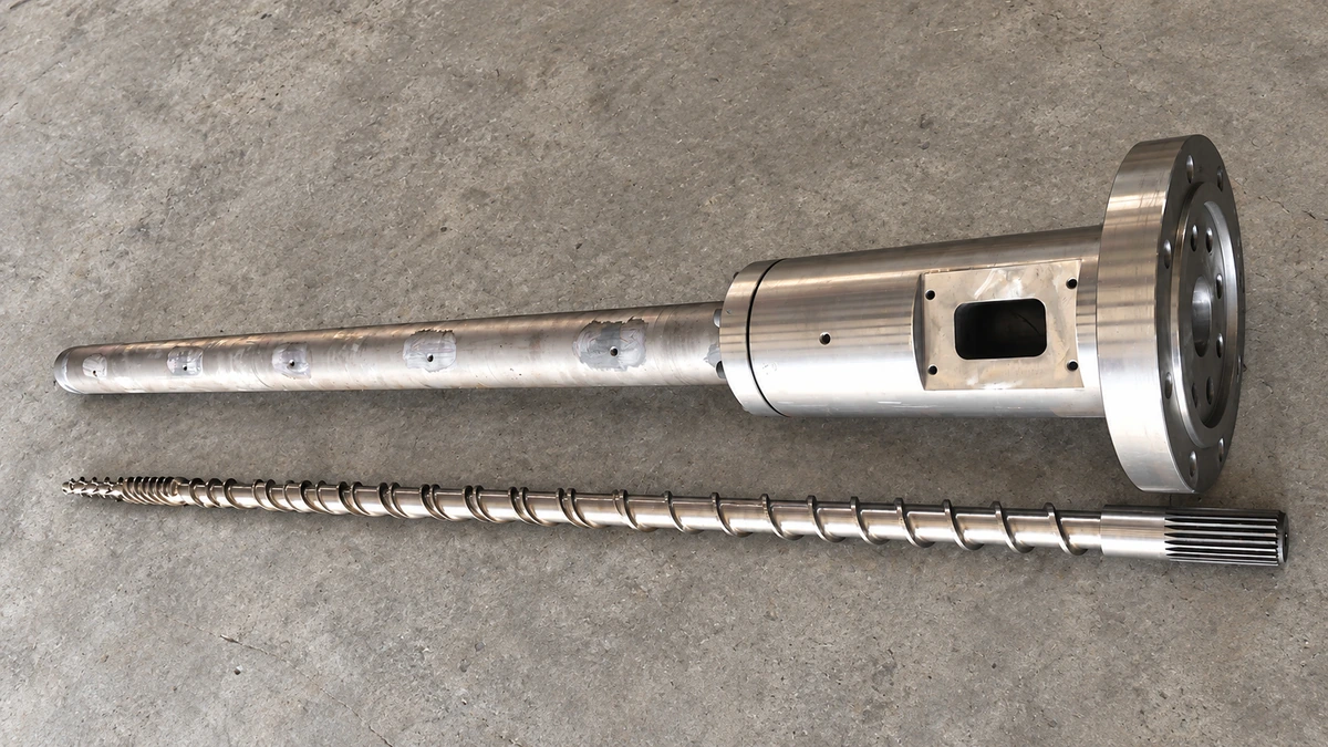
Why Your Single Screw Extruder Design Causes Extrusion Defects
Nov 13, 2026
Learn how single screw extruder design parameters—L/D ratio, compression ratio, channel depth, and mixing elements—affect melt quality, throughput, and defects.
Read Article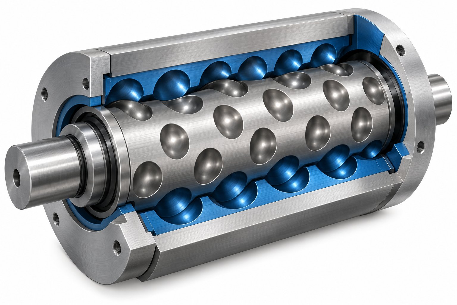
Cavity Transfer Mixer: The Blender Your Extruder Didn't Know It Needed
Nov 13, 2026
Learn how a cavity transfer mixer (CTM) upgrades single-screw extruder mixing. Covers working principles, key parameters, integration, applications, and comparisons.
Read Article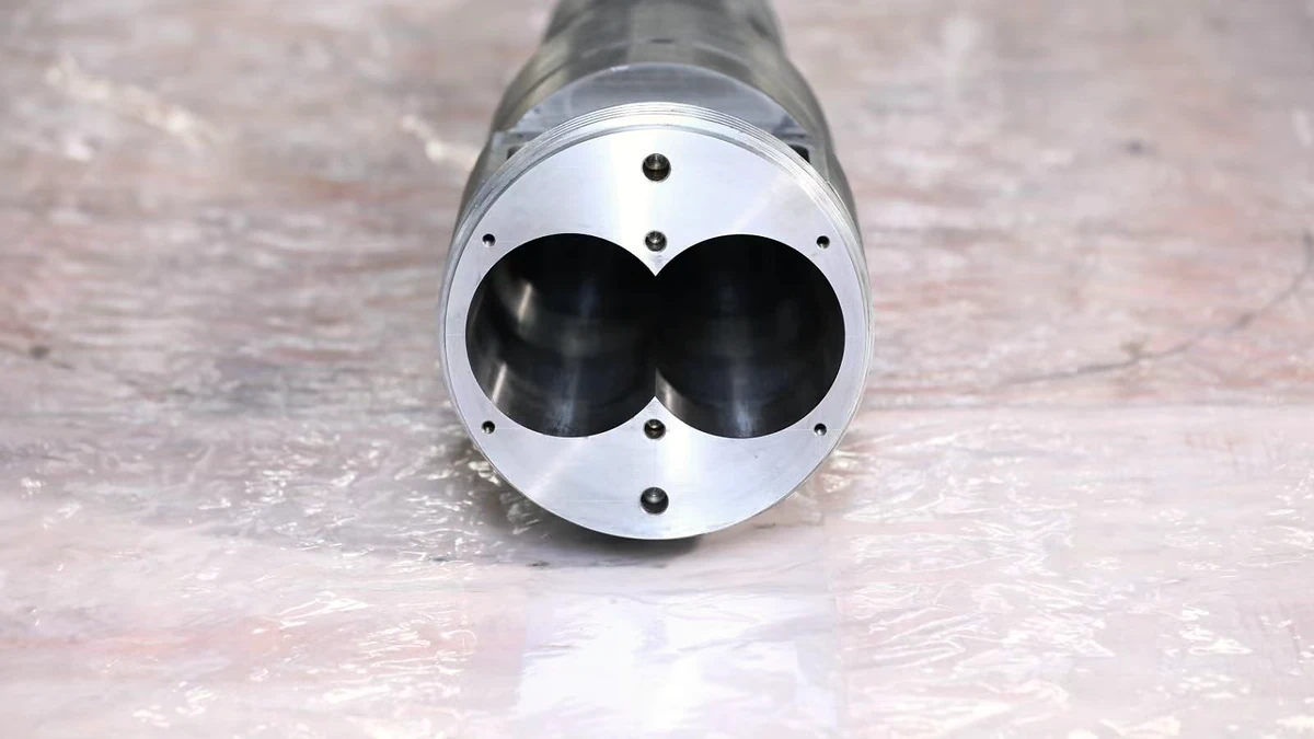
Extruder Barrel Alignment Decoded: Tolerances Most Plants Miss
Nov 13, 2026
Learn extruder barrel alignment tolerances, laser procedures, thermal offsets, and proactive schedules most plants miss — for single-screw and twin-screw lines.
Read ArticleLooking for something else?
Search by material, symptom or product and jump straight to the relevant page.
These are navigation suggestions based on keyword matching — not a quotation, not a delivery commitment, and not a substitute for engineering review. Final specification is confirmed by our engineers against your drawings and processed material.
Need help with screw barrel selection?
Share your machine model, processed material and application. Our team can help with pricing and technical support.