

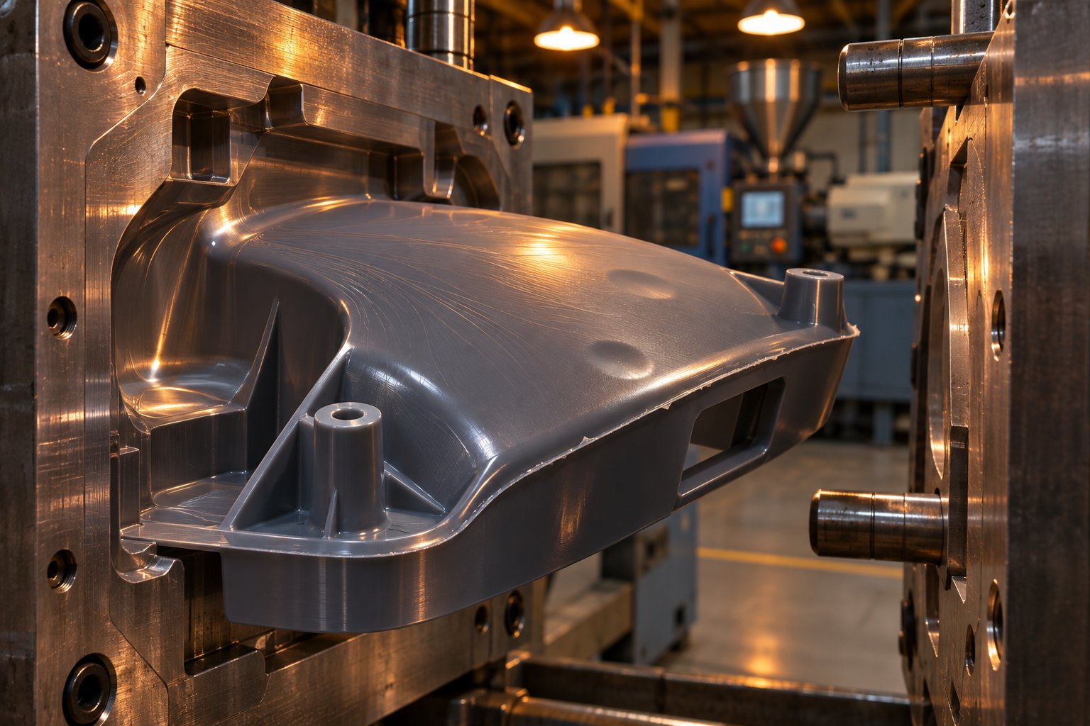
Why Injection Molding Defects Demand a Systematic Response
Injection molding defects are any deviations from a part's intended geometry, surface finish, or mechanical properties. They can stem from process settings, tooling conditions, material behavior, or part design choices--and more often than not, several of these variables act together. That overlap is exactly why a simple defect catalog falls short on the production floor. You fix one problem, and another appears because the root causes are tangled.
This guide takes a different approach. Instead of listing defects in isolation, it treats every quality issue as part of an interconnected system--one where adjusting a single parameter can ripple across multiple outcomes. The economic motivation is clear: scrap, rework, delayed shipments, and customer rejections all erode profitability quietly. Even seemingly minor issues like black specks in injection molding or parts sticking in injection molding can cascade into line stoppages and missed delivery windows when left undiagnosed.
Most injection molding defects share overlapping root causes, so understanding how the entire system interacts matters far more than memorizing individual fixes.
What Counts as an Injection Molding Defect
The term covers a broad spectrum. Cosmetic blemishes--flow lines, splay marks, surface discoloration--affect appearance. Dimensional deviations like warpage or excessive shrinkage prevent parts from fitting assemblies. Structural weaknesses such as internal voids or poor weld-line integrity compromise long-term performance under load. What qualifies as "acceptable" depends heavily on the end-use industry. An automotive Class-A exterior panel demands far stricter visual standards than a hidden structural bracket, while medical device enclosures and consumer electronics housings each impose their own thresholds for the same defect type.
Why a Systems Approach Beats a Defect Checklist
Imagine you're troubleshooting part sticking after ejection. You reduce pack pressure--and sink marks appear on the opposite side of the part. This kind of trade-off is the norm, not the exception. Real production floors deal with interacting variables where material properties, processing parameters, and mold design all influence one another simultaneously. Throughout this article, you'll see a structured troubleshooting hierarchy applied to every defect category: check process parameters first (they're the fastest and cheapest to change), then evaluate material considerations, and finally investigate mold or part-design modifications. A Pareto analysis of defect types in injection molding quality control helps prioritize which issues to tackle first when multiple problems surface at once.
How This Guide Is Organized
The sections ahead move from framework to specifics. First, you'll find a defect severity classification system for smarter production decisions. A root cause analysis framework follows, giving you a reusable diagnostic method. From there, the guide dives into surface defects, dimensional and structural failures, and fill-related problems--each examined through the four root-cause categories. A dedicated section on resin-family behavior maps common materials to their most likely defect patterns. The article closes with the concept competitors overlook entirely: defect interaction matrices that reveal why fixing one issue often creates another, plus a first-response protocol for mid-run quality events.
Classifying Defect Severity for Smarter Production Decisions
Not every flaw demands the same response. A faint flow mark on a hidden interior bracket is a very different problem than a void buried inside a load-bearing clip--even though both qualify as defects. The trouble is, many production teams treat all quality deviations with the same urgency, which either wastes time on cosmetic issues or, worse, lets structural problems slip through. A clear severity classification system cuts through that confusion and gives floor teams a shared language for making faster, better-informed decisions.
Think of defect severity in three tiers:
- Cosmetic defects -- surface-only issues such as minor flow marks, gate vestige, slight discoloration, or plastic splay that do not reduce mechanical performance. Their acceptability hinges entirely on the end-use industry and customer specification.
- Structural defects -- problems like sink marks, internal voids, injection molding stress marks, and weak weld lines that compromise part integrity. A part may look fine visually yet fail under load, vibration, or thermal cycling in the field.
- Functional failures -- short shots, severe warpage, mold mismatch, or excessive flash that prevent the part from assembling, sealing, or performing its intended function at all.
This three-tier framework helps you decide in seconds whether to document and continue, adjust process parameters on the fly, or halt the press and launch a full root cause investigation.
Cosmetic Defects and Industry-Specific Tolerances
Here's where context changes everything. A splay mark in injection molding that would trigger immediate rejection on an automotive Class-A exterior panel might be perfectly acceptable on a packaging lid that consumers never scrutinize. The same defect type can carry entirely different consequences depending on the industry.
Automotive Class-A surfaces--think dashboard fascias, exterior trim, and center console covers--demand the highest visual standards. These surfaces undergo inspection at close range, often under controlled lighting at specific angles. Medical device enclosures operate under strict regulatory requirements where even minor cosmetic blemishes can raise questions about overall manufacturing control, even if the flaw itself poses no patient risk. Consumer electronics housings occupy a middle ground: visible surfaces need to be clean and consistent because end users associate surface quality with product reliability. Packaging, by contrast, prioritizes function over aesthetics in most cases.
The following matrix maps common defect types against industry tolerance levels to give you a practical reference:
| Defect Type | Automotive Exterior | Automotive Interior | Medical | Consumer Electronics | Packaging |
|---|---|---|---|---|---|
| Flow lines | Zero tolerance | Limited acceptance | Limited acceptance | Limited acceptance | Generally acceptable |
| Splay / silver streaks | Zero tolerance | Zero tolerance | Zero tolerance | Limited acceptance | Generally acceptable |
| Gate vestige | Zero tolerance | Limited acceptance | Limited acceptance | Limited acceptance | Generally acceptable |
| Sink marks | Zero tolerance | Limited acceptance | Zero tolerance | Limited acceptance | Generally acceptable |
| Minor discoloration | Zero tolerance | Limited acceptance | Zero tolerance | Zero tolerance | Limited acceptance |
| Weld lines (visible) | Zero tolerance | Limited acceptance | Limited acceptance | Limited acceptance | Generally acceptable |
| Short shots | Zero tolerance | Zero tolerance | Zero tolerance | Zero tolerance | Zero tolerance |
| Flash | Zero tolerance | Limited acceptance | Zero tolerance | Zero tolerance | Limited acceptance |
Notice that short shots receive zero tolerance across every column--they're functional failures regardless of industry. Meanwhile, a visible weld line that's merely cosmetic on a packaging container becomes unacceptable on an automotive exterior panel. Establishing these tolerance boundaries with your customer before production starts prevents subjective disputes at the inspection table later.
Structural Defects That Compromise Part Performance
Structural defects are deceptive. A part can pass visual inspection, meet dimensional checks, and still carry hidden weaknesses that lead to field failures weeks or months after shipment. That gap between what you can see and what actually matters mechanically is where the most costly quality escapes occur.
Internal voids, for example, reduce the effective cross-section of a wall or rib. Under cyclic loading or impact, the void acts as a stress concentrator--a starting point for crack propagation. Weak weld lines present a similar risk. When two melt fronts converge at a temperature too low for full molecular entanglement, the resulting bond may have only 50-80% of the base material's tensile strength. If that weld line happens to sit at a snap-fit latch or a screw boss, the part fails in service even though it looked perfect out of the mold.
Injection molding stress marks--visible as whitening, crazing, or subtle surface distortions--signal residual stress locked into the part during cooling. These stresses may not cause immediate failure, but exposure to certain chemicals, UV light, or elevated temperatures can trigger environmental stress cracking over time. Semi-crystalline resins and amorphous resins respond differently to residual stress, a material-specific nuance explored later in this guide.
The key takeaway: visual inspection alone is insufficient for catching structural defects. Cross-sectioning sample parts, performing mechanical testing at regular intervals, and tracking process parameters that influence internal part quality--pack pressure, cooling uniformity, melt temperature--are all essential layers of defense.
When to Stop Production vs. When to Adjust and Continue
This is the decision that separates reactive shops from disciplined operations. When a defect appears mid-run, floor teams face a judgment call with real financial consequences on both sides: stopping a press costs money in downtime, but shipping marginal parts costs far more in customer rejections, warranty claims, or recalls.
A practical decision framework looks like this:
- Cosmetic defect within customer spec: Document the observation, note the shot numbers affected, verify that the defect is not trending worse, and continue running. Increase sampling frequency temporarily to confirm stability.
- Cosmetic defect outside customer spec but not worsening: Attempt a minor process adjustment--injection speed, melt temperature, or pack profile--within the validated process window. If the defect resolves within a defined number of shots, resume normal production. If it doesn't, escalate.
- Structural defect detected: Halt the press. Quarantine suspect parts. Launch a root cause investigation before restarting. Structural issues rarely fix themselves, and running while hoping they'll improve only grows the pile of scrap or, worse, ships compromised parts.
- Functional failure (short shot, severe warpage, flash preventing assembly): Stop immediately. These defects signal a fundamental breakdown--insufficient clamp force, a blocked gate, a material flow problem, or mold mismatch between halves--that process tweaks alone are unlikely to resolve.
This business-decision layer of defect management is something many troubleshooting guides skip entirely, yet it's the layer that determines whether your quality system actually protects margins. Having these criteria agreed upon in advance--documented in a control plan--removes ambiguity from shift-to-shift decision-making.
Severity classification, though, only tells you how urgently to respond. It doesn't tell you where to look for the cause. That's where a structured root cause analysis framework becomes indispensable--a diagnostic method you can apply consistently, regardless of which defect tier you're facing.
A Root Cause Analysis Framework for Every Defect
Knowing a defect's severity tells you how fast to react. But speed without direction just creates more confusion--and potentially more problems. Picture a technician who spots sink marks mid-run and immediately cranks up pack pressure. The sinks disappear, but now the parts are flashing at the parting line. Another adjustment follows, then another. Within twenty minutes, the process is so far from its validated settings that nobody can trace what actually fixed what--or what broke next.
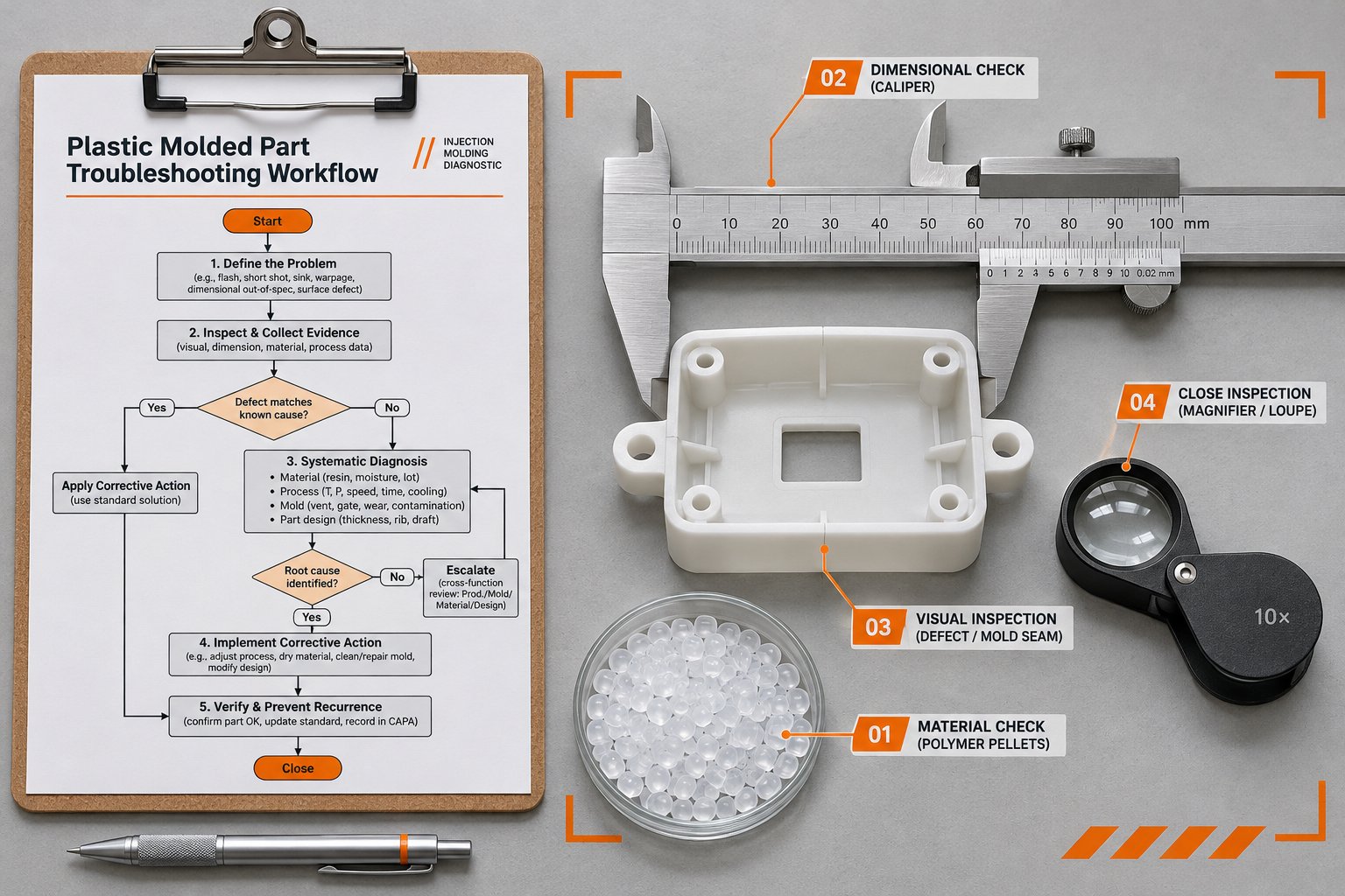
That reactive cycle is the single biggest source of wasted time on most molding floors. The antidote is a structured root cause analysis (RCA) framework--a repeatable diagnostic sequence that channels your investigation toward the likeliest cause with the least disruption and cost. Unlike isolated troubleshooting tips, this framework works regardless of the defect type because it's organized around a cost-of-change hierarchy that mirrors how real production environments operate.
The core logic is straightforward: check process parameters first, because they're the fastest and cheapest to adjust. If the process isn't the issue, examine material considerations. Only after ruling those out should you invest in mold or tooling modifications--the slowest, most expensive changes. This hierarchy isn't arbitrary. It reflects the practical reality that dialing a pack pressure up by 50 bar takes seconds, switching a material lot takes minutes, but modifying a cooling channel or relocating a gate takes days or weeks.
The Four Root-Cause Categories Explained
Every injection molding defect traces back to one or more of four root-cause categories. Understanding each one--and knowing what levers each contains--is the foundation for any effective troubleshooting chart.
1. Process parameters. These are the variables you control directly from the machine's HMI: melt temperature, barrel zone profiles, injection speed and speed profiles, pack pressure and pack time, cooling time, back pressure, screw RPM, and decompression settings. Process parameters are the first place to look because they're infinitely adjustable and immediately reversible. A shift in melt temperature of just 5-10 degrees Celsius can make the difference between clean fill and burn marks at flow-path endpoints.
2. Mold and tool design. This category covers everything physically built into the mold: gate type and location, runner system layout (cold vs. hot runner), venting depth and placement, cooling channel geometry, draft angles, parting-line fit, ejector pin location, and surface finish. Mold-related causes are trickier to address because changes require pulling the tool, machining, and re-qualifying. Yet some of the most persistent defects--chronic short shots in a thin-wall section, recurring burn marks at a dead-end rib--are fundamentally tooling problems that no amount of process adjustment will fully resolve.
3. Material selection and handling. Resin family, specific grade, moisture content, regrind ratio, additive compatibility, colorant dispersion, and lot-to-lot viscosity variation all live here. Material issues are common causes of quality issues in custom molded plastic packaging and precision components alike. A nylon resin dried to 0.20% moisture might mold perfectly, but the same resin at 0.08% can become so viscous that it short-shots thin sections. Regrind ratios above the manufacturer's recommendation degrade mechanical properties and introduce contamination. These variables sit between process and tooling in terms of correction speed--you can often swap a material lot or adjust a dryer in under an hour, but sourcing a different grade or qualifying a new colorant takes considerably longer.
4. Part design. Wall thickness uniformity, rib-to-wall thickness ratios, boss design, undercuts, draft angles, corner radii, and flow-length-to-thickness ratios all influence how plastic fills, packs, cools, and ultimately performs. Part design is the hardest category to change post-tooling because modifications ripple back into the mold, the assembly, and sometimes the entire product architecture. Still, recognizing a design-driven defect early saves enormous cost compared to chasing phantom process solutions for months.
The cheapest fix is always the one you try first--process, then material, then mold, then part design. Reverse that order and you'll spend weeks solving what might have been a five-minute adjustment.
Building a Troubleshooting Flowchart
A framework is only useful if it translates into action. When a defect appears--whether it's splay on a medical housing or warpage on an automotive bracket--the diagnostic sequence should follow the same disciplined path every time. Imagine it as a decision tree where each branch either confirms or eliminates a root-cause category before you move to the next.
Here's the general diagnostic sequence a production engineer should follow:
- Verify the defect is reproducible. Run several more cycles and inspect additional shots. A one-off anomaly--a single short shot caused by a momentary hydraulic hiccup--doesn't warrant a full investigation. If the defect repeats consistently, proceed. Note the cavity, location on the part, and frequency.
- Review recent process changes. Compare current machine settings against the validated setup sheet. Did someone adjust melt temperature between shifts? Was the cooling time shortened to hit a cycle-time target? Even small, undocumented changes can trigger new defects. This step alone resolves a surprising number of issues.
- Check material lot and drying status. Confirm the resin grade and lot number match the process validation records. Verify hopper and dryer conditions--dew point, residence time in the dryer, and regrind ratio. Moisture-related defects like splay are among the most common yet most preventable problems in the industry.
- Inspect mold condition. Examine venting channels for blockage, parting-line surfaces for wear or damage, cooling lines for adequate flow rate and temperature delta, and ejector pins for proper function. A vent that was clean last week can accumulate enough deposit from off-gassing additives to cause burn marks today.
- Evaluate part geometry against DFM guidelines. If the first four steps haven't identified the root cause, revisit the part design. Is there a thick-to-thin wall transition creating a pressure-drop problem? Does a rib-to-wall ratio exceed the 60-65% guideline? Are there undercuts generating vacuum lock during ejection? Design-driven defects typically manifest from the very first production run, so if a defect is new and sudden, design is less likely the culprit--but it should still be confirmed.
When multiple defect types appear simultaneously--say, flash on one cavity, sink marks on another, and occasional burn marks near a vent--trying to address everything at once leads to chaos. This is where Pareto analysis becomes essential. Rank the defects by frequency and severity, then tackle the highest-impact issue first. In many cases, resolving the dominant defect also reduces or eliminates secondary ones, because the root causes overlap. For example, a blocked vent might simultaneously cause burn marks at fill endpoints and short shots in adjacent thin sections--clearing the vent fixes both.
This same diagnostic logic applies well beyond injection molding. Engineers familiar with rotomolding defects or other polymer processing issues will recognize the pattern: systematic elimination beats guesswork every time. The difference in injection molding is the sheer number of interacting variables, which makes the structured approach even more critical.
Documenting Root Causes for Continuous Improvement
Finding the root cause is only half the value. Capturing it in a structured log is what prevents the same issue from resurfacing next week, next quarter, or the next time a new operator runs the job.
An effective RCA log doesn't need to be complicated. At minimum, it should record:
- Defect description and location -- what the defect looked like, which cavity it appeared in, and where on the part it occurred.
- Date, shift, and machine -- essential context for spotting patterns across equipment or personnel changes.
- Root-cause category -- process, material, mold, or design. This tagging allows you to run trend reports later.
- Specific cause identified -- for example, "hopper dryer dew point had drifted to -15C instead of -40C, causing moisture-related splay."
- Corrective action taken -- what was changed, and the exact settings or conditions after correction.
- Verification results -- confirmation that the defect disappeared and did not return over a defined production window.
- Preventive action -- what systemic change was implemented to stop recurrence, such as adding a dryer alarm setpoint or updating the setup sheet.
Over time, this documentation reveals patterns that no single troubleshooting event can show. You might discover that 40% of your quality issues trace back to material handling, prompting investment in better drying equipment or incoming resin inspection. Or you might find that a particular mold consistently produces burn marks after every 10,000-cycle interval, signaling a vent-cleaning PM task that should be scheduled proactively rather than reactively.
The RCA log also bridges shift changes and personnel turnover. When an experienced process technician leaves and a newer team member encounters the same defect six months later, the documented history provides a head start instead of forcing a diagnosis from scratch. As one evidence-led root-cause methodology puts it: contain the affected lot, preserve traceability, test the most likely hypothesis under controlled conditions, and then update the control record so the correction sticks.
With this diagnostic framework in hand, you have a reliable method for tracing any defect back to its origin. The real test comes when you apply it to specific failure modes--starting with the surface-level defects that are often the first visible sign of deeper process instability lurking beneath.
Surface Defects from Splay to Burn Marks and Black Specks
Surface defects are the most visible symptoms a molding process can produce--and often the earliest warnings that something deeper is going wrong. A silver streak near a gate or a brown discoloration at the end of fill might look like a minor cosmetic blemish, but each one carries a diagnostic fingerprint pointing back to moisture, heat, shear, trapped gas, or contamination. Apply the troubleshooting hierarchy from the previous section--process first, then material, then mold--and these fingerprints start to tell a clear story.
Splay and Silver Streaks--Moisture, Shear, or Degradation
Splay in injection molding shows up as shiny, V-shaped streaks or flower-like spray patterns radiating along the flow direction from the gate. What makes splay tricky is that three entirely different mechanisms produce it, and each one leaves a slightly different visual signature.
Moisture splay is the most common and the most preventable. When resin pellets carry excess moisture into the barrel, water turns to steam under processing temperatures and gets trapped in the melt. The result is evenly distributed silver streaks that populate the surface densely in severe cases. Hygroscopic resins like PA6, PC, and ABS are especially vulnerable--nylon, for instance, requires drying to below 0.02% moisture content before molding. A practical benchmark is to always verify moisture content with an air shot before starting production, because even properly dried material can reabsorb moisture while sitting in an uninsulated hopper.
Shear-induced splay stems from excessive frictional heating inside the screw and barrel. When injection speed is too high, back pressure too aggressive, or the screw geometry creates localized hot spots, the resin overheats at the molecular level. The streak pattern often appears more erratic than moisture splay and concentrates near gate areas where shear rates peak. Worn screw flights and check rings amplify this problem because they increase residence-time variability--some material races through while other pockets stagnate and overheat.
Thermal degradation splay occurs when resin sits in the barrel too long, breaking down chemically and releasing carbon dioxide and other volatiles. You'll often notice a slight color shift--darkening along the sprue--alongside the silver streaks, which may resemble comet-shaped trails rather than uniform lines. Dead spots in the barrel or nozzle, oversized barrel capacity relative to shot size, and excessively long cycle times all contribute. When screw geometry is mismatched to the resin or worn beyond tolerance, uneven melting and material-retention zones accelerate degradation. For molders who trace splay back to plasticizing hardware condition, suppliers like NANHAIYA offer custom injection molding screw barrels designed around the specific resin and application--their technical review evaluates screw geometry, wear patterns, melting efficiency, and material-retention concerns to address these root causes at the hardware level.
The diagnostic sequence follows the hierarchy: verify drying conditions first (cheapest fix), then review injection speed and barrel temperature profiles, then inspect screw and barrel condition. Jumping straight to hardware replacement before checking a dryer's dew point is a common and expensive mistake.
Burn Marks and Gas Traps
Injection moulding burn marks appear as brown or black scorched areas, almost always at the last-to-fill regions of a cavity--deep ribs, far corners, and flow-path endpoints where air has nowhere to escape. The physics mirrors a diesel engine: as the melt front advances, it compresses trapped air or volatiles ahead of it. When venting is inadequate or fill speed is too high at end of fill, that compressed gas undergoes adiabatic heating and can spike to 300-600 degrees Celsius--hot enough to char the polymer on contact.
A gas mark in injection moulding is essentially the same phenomenon at a milder intensity. Where a full diesel burn leaves obvious charring, a gas mark may present as a faint discoloration or surface dullness at the same predictable locations.
Walking through the troubleshooting hierarchy for burn marks:
- Verify venting adequacy. Check vent depth and location at the burn site. Vents clog over time from off-gassing additives and mold deposits--a phenomenon related to plate out in injection molding, where additive residues accumulate on mold surfaces. Cleaning vents on a scheduled interval (some shops do it every 4 hours for problematic tools) is often the single most effective corrective action.
- Reduce injection speed during the final fill phase. Slowing the last 5-10% of the stroke gives trapped gas more time to escape through existing vents. This is a zero-cost diagnostic test: if the burn clears, air entrapment is confirmed.
- Check mold parting-line condition. Worn or damaged parting surfaces can seal vents shut under clamp pressure, trapping gas that would otherwise escape. Excessive clamp tonnage can have the same effect even on a well-maintained tool.
- Confirm barrel temperatures are within resin manufacturer recommendations. Overheated melt generates more volatile gases, compounding the venting problem. Lower melt temperature only after venting and speed have been addressed--dropping barrel heat alone rarely solves a true air-trap burn.
A second, distinct burn mechanism--shear burning--originates at the gate rather than end of fill. When resin is forced through an undersized gate at high velocity, frictional heat degrades the polymer locally, leaving discoloration along the high-velocity flow path. The fix here targets gate geometry and injection speed profiling rather than venting.
Black Specks, Discoloration, and Flow Lines
Black specks are among the most frustrating surface defects because they can appear intermittently and resist simple process adjustments. These dark contaminants are almost always degraded polymer fragments--carbonized material that has broken loose from inside the processing equipment and entered the melt stream.
The most common sources include dead spots in the barrel or hot runner where molten plastic stagnates and overheats over time, worn screw surfaces that create pockets for material retention, and inadequate purging between color or material changes. Clear and light-colored resins make even microscopic specks glaringly obvious, turning what might go unnoticed in a black part into a rejection-worthy defect in a white or transparent one.
Worn or mismatched screw geometry intensifies the problem. As screw flights wear, the clearance between flight and barrel wall increases, creating additional dead zones where material degrades into carbon deposits. These deposits eventually break free during normal cycling and appear as random black spots in finished parts. When diagnosis points to screw-related degradation, replacing the plasticizing components with properly specified hardware--matched to the resin's viscosity, thermal sensitivity, and processing window--is more effective than endlessly compensating with purge cycles. NANHAIYA's custom screw barrels, for example, are engineered around specific machine and resin requirements to minimize dead zones and improve melting consistency.
Discoloration--a broader color shift rather than discrete specks--typically stems from overheated melt, contaminated regrind, or incompatible colorant carriers. Flow lines, by contrast, appear as wavy patterns or off-color bands on the part surface. They form when the melt front cools prematurely as it flows across the cavity wall, creating visible boundaries between slightly different temperature zones.
Visual identification cues help distinguish these defects quickly on the production floor:
- Black specks: Discrete dark particles, often randomly distributed. May appear as dots or short streaks. Frequency can increase after long production runs or color changes.
- Discoloration: Broad color shift or yellowing across regions of the part, not isolated to particles. Often worst near the sprue or in areas with longest melt residence.
- Flow lines: Wavy, ring-like patterns on the surface following the flow path. Typically most visible on flat, glossy surfaces. Caused by melt-front hesitation or temperature inconsistency rather than contamination.
- Gate blush: A hazy or matte area immediately surrounding the gate, caused by high shear stress as material enters the cavity. Distinguished from splay by its localized, circular pattern.
Each of these defects responds to different levers within the troubleshooting hierarchy. Black specks demand equipment cleaning and hardware inspection. Discoloration calls for temperature and material review. Flow lines respond to melt temperature increases, injection speed profiling, and mold temperature adjustments. Gate blush typically requires gate geometry changes or speed reduction at the initial injection phase.
Surface defects, though, represent only half the diagnostic picture. Plenty of parts emerge from the mold looking pristine on the outside while hiding dimensional deviations and internal weaknesses that only reveal themselves under load, during assembly--or worse, in the customer's hands.
Dimensional and Structural Defects That Weaken Parts
A part that looks flawless on the outside can still fail in the field. Dimensional deviations and internal weaknesses don't announce themselves at the inspection table the way a burn mark or a silver streak does--they hide inside the wall, distort after ejection, or wait until a snap fit is loaded before cracking. These defects erode part performance silently, and because they're less visible, they often persist longer before anyone investigates.
What makes this category especially challenging is that the root causes are rooted in polymer physics. Plastics shrink as they cool, and they never shrink perfectly uniformly. Every sink mark, every warped panel, and every internal void traces back to some form of shrinkage imbalance--driven by wall geometry, cooling gradients, packing dynamics, or material crystallization behavior. Understanding that underlying science turns a troubleshooting guide for injection molding into something far more powerful than a list of parameter tweaks: it gives you the ability to predict where problems will form before they appear.
Sink Marks--Differential Shrinkage at Thick Sections
Sink marks are small, localized depressions on the part surface--shallow craters that form directly opposite thick features like ribs, bosses, and screw columns. They're one of the most common defect types in injection molding, and also one of the most persistently misdiagnosed.
The mechanism is straightforward once you picture what happens inside the cavity. When molten plastic fills the mold, the outer skin in contact with the cooler cavity wall solidifies first, forming a rigid shell. Meanwhile, the core--especially in thick sections where more material is concentrated--remains molten and continues to cool and contract. If the packing phase cannot feed enough additional material into those thick zones to compensate for this volumetric contraction, the still-molten core pulls the solidified surface inward, creating a visible depression.
Several root causes feed into this sequence:
- Inadequate pack pressure or pack time. If packing ends before the gate freezes, material stops flowing into the cavity while the core is still shrinking. The result is an unfed thick section that sinks.
- Excessive wall thickness or rib-to-wall ratio. A rib that's thicker than roughly 50-60% of the adjacent wall creates a mass of material that cools far slower than its surroundings. The larger the thermal mismatch, the deeper the sink.
- Insufficient cooling. Hot spots in the mold--caused by poorly positioned cooling channels, blocked waterlines, or inadequate flow rates--extend the time thick sections stay molten, amplifying shrinkage differential.
- Early gate freeze-off. If the gate is too small or positioned far from the thick feature, it solidifies before the packing phase has finished compensating for core shrinkage. No material can enter the cavity once the gate seals.
When you encounter sink marks, the troubleshooting sequence should follow the cost-of-change hierarchy:
- Increase pack pressure and extend hold time--the fastest, zero-cost adjustment. Monitor cushion stability to confirm that material is actually available to pack.
- Verify gate size allows adequate packing. If the gate freezes too early, even maximum pack pressure won't help. A gate that's steel-safe can be opened slightly without major mold work.
- Reduce melt temperature slightly. Lower melt brings less heat into the cavity, reducing total shrinkage that the packing phase must overcome. Be cautious--dropping too far risks incomplete fill or poor weld-line strength.
- Redesign thick sections if process limits are exhausted. Coring out solid bosses, reducing rib-to-wall ratios, or redistributing material mass are the definitive fixes when the geometry is simply too aggressive for any process window to accommodate.
One nuance worth noting: the optimal rib-to-wall ratio depends on the resin. Crystalline materials like nylon and POM shrink more overall and are more sensitive to rib thickness than amorphous materials like ABS or polycarbonate. A rib ratio that works perfectly in ABS may produce visible sinks in polypropylene--a resin-specific variable that generic troubleshooting charts rarely capture.
Warpage--When Internal Stresses Release After Ejection
Imagine pulling a part out of the mold and watching it slowly twist or bow over the next few minutes. That's warpage--and it's arguably the most complex defect injection molding engineers face, because its causes are deeply intertwined with polymer behavior at the molecular level.
The physics boils down to one principle: if every region of the part shrinks at the same rate in every direction, the part gets uniformly smaller but retains its intended shape. The moment any element shrinks differently from its neighbors, internal stresses develop. When those stresses exceed the part's structural rigidity at ejection temperature, the part deforms--bowing, twisting, or pulling out of dimensional tolerance.
Four types of shrinkage variation drive warpage:
- Regional shrinkage differences. Areas near the gate pack more densely than areas at end of fill, creating a shrinkage gradient from thick, well-packed zones to thinner, under-packed regions.
- Through-thickness variation. When one mold half runs hotter than the other, the side that cools slower shrinks more. The part bows toward the hotter side, much like a bimetallic strip curling when heated.
- Directional (anisotropic) shrinkage. Molecular orientation during flow means the plastic doesn't shrink equally in all directions. This effect is especially pronounced in semi-crystalline and fiber-filled resins.
- In-plane vs. thickness shrinkage. The mold physically restrains in-plane shrinkage while the part is inside the cavity, but it cannot restrain shrinkage through the wall thickness. This mismatch builds residual stress that releases after ejection, particularly at corners and thick-to-thin transitions.
Distinguishing between process-induced and design-induced warpage is critical for directing your corrective efforts in the right direction.
Process-induced warpage stems from uneven cooling, overpacking on one side, or inconsistent mold temperature between halves. These causes are addressable without modifying the tool--balance coolant flow rates between mold halves, equalize cavity and core temperatures, and review the packing profile to avoid pressure-induced density gradients.
Design-induced warpage arises from non-uniform wall thickness, asymmetric features that cool at different rates, or geometric stiffness that differs from one axis to another. A flat, thin-walled panel with a row of ribs on one side, for example, will always tend to bow because the ribbed side is structurally stiffer and cools differently from the flat side. No amount of process optimization fully corrects a geometric imbalance like this.
Material type adds another layer. Amorphous resins like ABS, PC, and polystyrene exhibit relatively low and uniform shrinkage, so their warpage is driven primarily by differential cooling and molecular orientation effects. Semi-crystalline resins--PP, PE, PA, POM--shrink significantly more overall, and that shrinkage is highly directional. As polymer science explains, crystalline structures that form during cooling cause greater shrinkage perpendicular to the flow direction, while amorphous materials tend to shrink more parallel to flow. This means the same part geometry can warp in completely different ways depending on whether it's molded in polycarbonate or polypropylene.
Fiber-reinforced materials introduce yet another variable. Glass and carbon fibers resist shrinkage along their alignment axis but have no restraining effect perpendicular to it. The result is anisotropic shrinkage that can be dramatically different in-flow versus cross-flow, making warpage prediction especially challenging for filled compounds. Gate location becomes even more consequential, because it dictates fiber orientation patterns throughout the cavity.
Voids, Bubbles, and Internal Stress Marks
Voids and bubbles both manifest as hollow spaces inside the wall, but they originate from entirely different mechanisms--and confusing them sends your troubleshooting down the wrong path. Stress marks, a related but distinct failure mode, show up as whitening or crazing on or near the surface, signaling that residual stresses locked into the part during molding are approaching the material's limits.
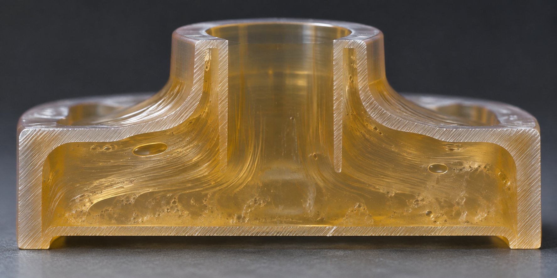
A vacuum void forms in thick sections when the outer skin freezes before the core has fully solidified. As the still-molten core contracts, it pulls away from itself internally, creating a hollow pocket. There's no gas involved--just material that didn't have a feed path to compensate for shrinkage. Vacuum voids share the same root cause as sink marks, and in fact, the two are alternate expressions of the same phenomenon: when packing is marginal, the part may sink on the surface, void internally, or do both.
A gas bubble, by contrast, involves actual gas trapped inside the melt. That gas can come from moisture flashing to steam, volatile additives breaking down, air entrained during screw recovery, or polymer degradation releasing CO2 and other byproducts. Unlike vacuum voids, gas bubbles can appear anywhere along the flow path because they travel with the melt front rather than forming only at thick-section locations.
A simple shop-floor test helps distinguish the two: slowly heating the defect area with a heat gun causes a vacuum void to collapse into a visible sink mark, while a gas bubble expands. Location is also diagnostic--voids concentrated at rib roots, boss bases, or the thickest cross-section are almost certainly shrinkage-driven, while randomly distributed bubbles suggest a gas source upstream in the barrel.
| Characteristic | Vacuum Void | Gas Bubble |
|---|---|---|
| Cause mechanism | Insufficient packing; core shrinks after skin solidifies, pulling material apart internally | Moisture, volatiles, entrained air, or thermal degradation introduce gas into the melt |
| Typical location | Thickest sections--rib roots, bosses, heavy wall transitions | Random throughout the part; may also cluster near the gate (shear/jetting) or at last-fill areas (trapped air) |
| Visual appearance in cross-section | Elongated or irregular cavity, often centered in the wall thickness; smooth inner surfaces | Spherical or near-spherical; may show discoloration if caused by degradation |
| Heat-gun test | Collapses into a sink mark | Expands |
| Primary corrective actions | Increase pack pressure and hold time; verify gate stays open long enough; reduce wall thickness or core out heavy sections | Verify resin drying; reduce barrel temperature; lower screw speed and increase back pressure; check for dead spots in barrel or hot runner |
Stress marks represent a different category of internal damage. They manifest as whitening (stress whitening in semi-crystalline resins), crazing (micro-crack networks in amorphous resins), or subtle surface distortions visible under angled light. These marks indicate that residual stresses frozen into the part during cooling are high enough to begin deforming the polymer structure at the molecular level.
Residual stress builds from several sources: overpacking that compresses material beyond its relaxed state, rapid cooling that locks in molecular orientation before chains can relax, and non-uniform cooling that creates competing thermal contraction forces within the wall. Parts with high residual stress may appear acceptable initially but fail under load, during assembly, or when exposed to chemicals that accelerate environmental stress cracking. Amorphous resins like polycarbonate and PMMA are particularly susceptible to stress-cracking in the presence of solvents, cleaning agents, or adhesives--even when the applied stress alone wouldn't cause failure.
The corrective approach mirrors the general framework: first, review packing profiles and reduce overpacking. Then, examine cooling balance and consider raising mold temperature modestly to allow more stress relaxation before ejection. Finally, if the stress marks trace to geometric stress concentrators--sharp internal corners, abrupt wall transitions, or inadequate radii--the fix moves into plastic injection mold repair or part redesign territory.
Dimensional and structural defects share a common thread: they're all expressions of what happens when plastic doesn't shrink the way the mold and process assumed it would. But shrinkage isn't the only variable that can go sideways during filling. An entirely different family of problems emerges when the melt doesn't reach where it needs to go--or goes where it shouldn't.
Fill and Flow Defects from Short Shots to Flash and Jetting
Shrinkage-driven defects punish you after the cavity is full. Fill and flow defects punish you during the filling itself--when molten plastic either can't reach the end of the cavity, escapes where it shouldn't, or enters the cavity in a way that ruins the surface before the part is even packed. Short shots, flash, jetting, gate blush, part sticking, and gate vestige all fall into this family, and they share a common trait: each one points back to some combination of mold condition, clamp force, gating design, or pressure balance.
What makes these defects especially instructive is how tightly they're coupled. Fixing one can directly trigger another if you're adjusting parameters in isolation--a dynamic that perfectly illustrates why injection molding defects demand systematic thinking rather than single-variable guesswork.
Short Shots and Flash--Two Sides of the Fill Balance
Think of short shots and flash as opposite ends of the same pressure scale. A short shot means the cavity didn't fill completely--the melt front stalled before reaching the last-to-fill region, leaving a visibly incomplete part. Flash means the opposite: molten plastic found a gap it wasn't supposed to enter--at the parting line, around ejector pins, across shutoff surfaces--and squeezed through it under pressure.
Here's the trap. You discover a short shot and the instinct is to boost injection pressure or raise melt temperature to push the material further. That might complete the fill, but if clamp tonnage is marginal or the parting-line surfaces are worn, that extra pressure now forces melt into gaps it previously couldn't penetrate. The short shot disappears, and flash takes its place. This inverse relationship is one of the clearest examples of why isolated troubleshooting fails on the production floor.
Short shot root causes span multiple categories in the troubleshooting hierarchy:
- Insufficient injection pressure or speed. The melt front loses momentum before reaching the end of fill, especially in thin-wall geometries where the flow-length-to-thickness ratio is aggressive.
- Restricted flow path. Undersized gates, partially frozen runners, or cold slugs blocking the sprue all reduce the effective cross-section available to the melt.
- Frozen gate. If the gate solidifies prematurely--before the cavity is completely filled--no amount of barrel pressure can push more material through.
- Inadequate venting. Trapped air at the end of fill creates back pressure that resists the advancing melt front. In severe cases, the melt simply cannot displace the compressed air and the cavity remains partially empty.
- Melt temperature too low. Cooler resin has higher viscosity, requiring more pressure to fill thin sections and long flow paths. It also freezes against cavity walls faster, narrowing the effective flow channel as fill progresses.
Flash root causes mirror short shots but from the excess-pressure side:
- Excessive injection or hold pressure. Driving more pressure than needed--especially during the transition from velocity to pressure control--creates a pressure spike that can separate mold halves or force melt into microscopic gaps.
- Worn parting surfaces. Over thousands of cycles, parting-line steel wears, shutoff faces erode, and ejector-pin bores enlarge. Each worn surface becomes a potential leak path for pressurized melt.
- Insufficient clamp force. When the separating force generated by cavity pressure across the projected area exceeds the press's clamp tonnage, the mold opens slightly and flash appears around the perimeter.
- Mold mismatch. Misaligned halves, platens out of parallel, or uneven tie-bar loading concentrate clamp force unevenly, leaving some parting-line regions under-clamped even when total tonnage seems adequate.
- High melt or mold temperature. Lower viscosity means the resin can penetrate smaller gaps at the same pressure--a material-behavior variable that process engineers sometimes overlook when a new resin lot flows slightly easier than the previous one.
A useful diagnostic detail: where the flash appears tells you what to check first. Flash around the entire parting line in every cavity suggests a clamp-force or pressure-spike issue. Flash in one localized area points to local wear or debris on the mold face. Flash around ejector pins indicates pin-bore clearance has opened up. Mapping the flash location before touching any settings saves considerable diagnostic time.
One critical caution: raising clamp force is only the correct response when the separating force genuinely exceeds the current setting and the mold's parting-line contact is uniform. Cranking up tonnage to mask a worn parting line or over-pressured process creates its own cascade of problems--crushed vents that cause burn marks, rolled parting-line edges that accelerate future wear, and even cracked cavity inserts. As industry documentation notes, flash that appears to resolve under high clamp force and then returns later is a telltale sign of mold damage being hidden rather than fixed.
Jetting and Gate Blush
Ideally, molten resin enters the cavity and immediately fans outward in a smooth, expanding front--what polymer engineers call fountain flow. The melt contacts the cavity wall, cools slightly to form a skin, and the next layer of incoming material flows behind it, expanding the front progressively until the cavity is full. This controlled pattern produces uniform surface quality and strong molecular bonding throughout the part.
Jetting breaks that pattern entirely. Instead of spreading outward from the gate, the melt stream shoots across the open cavity like water from a hose, folding back on itself as it hits the opposite wall. The result is a distinctive worm-like or snake-track pattern frozen into the part surface--a tangled rope of cooled material with poor bonding between each fold. Beyond the obvious cosmetic failure, jetting creates weak spots where the folded layers never fully fuse, making the defect structural as well as visual.
Jetting typically occurs when three conditions align: the gate is positioned so that the melt enters directly into an open cavity without immediately impinging on a wall or core pin, the initial injection speed is too high for the gate geometry, and the melt viscosity is low enough to maintain a coherent stream rather than breaking into fountain flow. Thin-wall parts with edge gates oriented parallel to a large open face are classic jetting candidates.
Solutions target the flow entry conditions:
- Redirect the gate. Aim the gate so the melt impinges on a cavity wall, core pin, or other obstruction immediately upon entry. This breaks the jet into fountain flow before it can cross the cavity.
- Reduce initial injection speed. A slower start allows the melt to establish contact with the cavity wall near the gate before higher-speed fill takes over. Many modern machines support multi-stage injection speed profiles specifically for this purpose.
- Increase melt temperature modestly. A slightly hotter, lower-viscosity melt tends to spread rather than stream. However, this must be balanced against other temperature-sensitive defects like injection molding splay or degradation.
- Enlarge or reshape the gate. A wider gate entrance spreads the melt over a larger area, reducing the velocity at the entry point and encouraging immediate fountain flow.
Gate blush is a related but distinct phenomenon. It appears as a hazy, matte, or discolored halo immediately surrounding the gate--a cosmetic flaw caused by extreme shear stress as material forces through the gate restriction. The high shear rate at the gate entrance fractures the melt surface, creating a rough texture or whitened zone that contrasts with the smoother cavity surface downstream. Heavy texturing on the mold surface can mask mild gate blush, but on high-gloss or Class-A parts, even subtle blush is grounds for rejection.
Gate blush responds to similar levers as jetting--slower initial fill speed, larger gate cross-section, and fan or tab gate designs that spread the shear over a wider entry. Gate type selection during mold design is ultimately the most effective prevention, because retrofit solutions after the tool is built are constrained by the existing steel geometry.
Part Sticking and Gate Vestige
You've achieved a complete fill with no flash, no jetting, and no blush--but the part won't release from the mold cleanly. Part sticking is one of those injection molding defects that can appear suddenly after thousands of trouble-free cycles, or it can plague a mold from the very first shot. Either way, it disrupts cycle time, damages parts, and risks damaging the mold itself if ejection force climbs too high.
Parts stick to the core or cavity side for several reasons:
- Insufficient draft angle. Surfaces parallel to the direction of mold opening grip the part during ejection. Even half a degree of additional draft can make the difference between clean release and sticking.
- Undercuts or surface texture. Textured surfaces, especially deep textures, act like tiny barbs that resist part release. The general rule is one degree of additional draft per 0.001 inch (0.025 mm) of texture depth.
- Vacuum formation. Deep cores or shut-off areas can create a vacuum between the part and the core surface as ejection begins. Without vacuum-relief provisions, the ejection system fights atmospheric pressure over the entire core area.
- Overpacking. Excessive hold pressure forces extra material into the cavity, causing the part to shrink tighter onto cores and features. This is yet another example of a fix for one defect (sink marks) causing a different one (sticking).
- Mold surface condition. Scratches, corrosion, or buildup on cavity or core surfaces increase friction during ejection. Regular polishing and mold-release maintenance prevent gradual surface degradation from becoming a sticking problem.
When parts sticking in injection molding becomes chronic, the diagnostic sequence follows the familiar hierarchy: first, check whether pack pressure or hold time has been increased recently (process). Then verify that no surface contamination or buildup is present (mold maintenance). Finally, evaluate draft angles and undercut geometry against DFM standards (tool design). Applying external mold release spray is a temporary band-aid, not a solution--if you're spraying every few cycles, something upstream needs correction.
Gate vestige is a different kind of post-ejection concern. Every gate leaves a mark where the runner system separated from the part. The size, shape, and cleanliness of that mark depend almost entirely on the gate type chosen during mold design--a decision made months before the first shot is ever fired.
Here's how the most common gate types compare in terms of vestige characteristics:
- Edge gate: Leaves a visible witness mark along the parting-line edge. Requires manual trimming or fixture-based cutting. Vestige size depends on gate cross-section--larger gates leave bigger marks but allow better packing.
- Sub-gate (tunnel gate): Shears automatically during ejection, leaving a small dot typically on a non-cosmetic B surface. Ideal for automated production. Limited in maximum size, which can restrict packing on larger parts.
- Pin gate (three-plate mold): Produces a small vestige that allows center or off-parting-line gating. Self-degating, with the runner pulled separately. Well-suited for round parts or multi-gated configurations.
- Hot-tip (thermal gate): Eliminates the cold runner entirely. Leaves a small vestige directly on the part surface where the hot runner tip contacts the cavity. Gate vestige can be noticeable on show surfaces, so placement matters.
- Valve gate (hot runner): Delivers the cleanest vestige available--a flush, nearly invisible mark. Sequential valve gating can also eliminate weld lines on large parts by firing gates in sequence as the flow front advances. The trade-off is higher tooling cost and added hot-runner complexity.
Gate vestige becomes a defect when it interferes with part function--preventing flush assembly, creating a sharp edge that fails safety requirements, or landing on a surface where customer specifications demand zero visible marks. The time to solve a vestige problem is during mold design review, not during production. Changing gate type after the tool is built typically requires significant mold modification.
Fill and flow problems highlight a recurring theme throughout plastic injection troubleshooting: every parameter adjustment pulls on multiple threads simultaneously. Boosting pressure to fill the cavity risks flash. Slowing injection to prevent jetting can leave the part short. Packing harder to prevent sinks causes sticking. These trade-offs are inescapable--but they become manageable when you understand which resins tolerate which adjustments. And that tolerance varies dramatically from one polymer family to the next.
How Resin Families Influence Defect Susceptibility
Every troubleshooting step covered so far--adjusting pack pressure, profiling injection speed, cleaning vents, checking draft angles--assumes you know how your specific resin will respond. But here's the problem: a parameter change that eliminates sink marks in ABS might intensify plastic warping in polypropylene. A melt temperature that prevents splay in polycarbonate could cause burn marks in POM. The resin itself isn't just another variable in the equation--it fundamentally shapes which defects are likely, how severe they'll be, and how much room you have to adjust before something else breaks.
This is one of the biggest gaps in most injection molding troubleshooting resources. They treat every resin as interchangeable, offering generic advice like "increase pack pressure" without acknowledging that the same fix produces radically different outcomes depending on whether you're running an amorphous or semi-crystalline polymer. Bridging that gap requires understanding the molecular-level differences that make each resin family behave the way it does.
Amorphous vs. Semi-Crystalline Resin Behavior
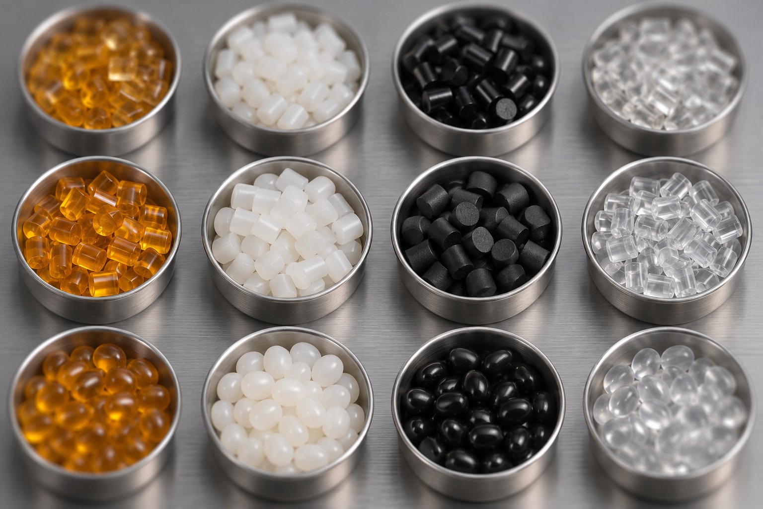
Imagine a drawer full of T-shirts tossed in randomly--they occupy a lot of space, and when you push down on the pile, it compresses a little but doesn't collapse dramatically. That's roughly how amorphous polymers behave at the molecular level. Their polymer chains are tangled and disordered, with no organized packing structure. When they cool, they contract gradually and relatively uniformly in all directions. Shrinkage values for amorphous resins like ABS, PC, PMMA, and PS typically fall in the range of 0.4-0.8%--modest enough that dimensional control is comparatively forgiving.
Semi-crystalline polymers tell a very different story. Picture those same T-shirts neatly folded and stacked--they suddenly take up far less space. Semi-crystalline resins like PP, PE, PA (nylon), and POM form organized crystalline regions called spherulites as they cool. That molecular reorganization squeezes out free volume aggressively, producing shrinkage values that can reach 1.5-3.0% or more. Crucially, that shrinkage isn't uniform. It's directional--greater perpendicular to the flow direction than parallel to it--because molecular orientation during filling biases where crystalline structures form.
This fundamental distinction ripples through nearly every defect category:
- Warpage: Semi-crystalline resins are far more prone to plastic warping because their higher, more directional shrinkage creates internal stress gradients that amorphous resins largely avoid. A flat PP panel warps in ways a PC panel of identical geometry simply won't.
- Sink marks: The greater volumetric contraction in semi-crystalline materials means thicker sections sink more aggressively. A rib-to-wall ratio that's perfectly safe in polycarbonate may produce noticeable sinks in nylon or polypropylene.
- Surface defects: Amorphous resins tend toward stress cracking and surface blemishes like splay and gate blush, partly because their stiffer melt behavior concentrates shear stress at the surface. Semi-crystalline resins, flowing more easily at typical processing temperatures, are less prone to shear-related surface defects but more susceptible to issues tied to crystallization--such as surface haze from premature crystallization at the mold wall.
- Dimensional stability: Amorphous parts reach their final dimensions relatively quickly after ejection. Semi-crystalline parts can continue shrinking for hours as residual crystallization completes--a phenomenon that complicates inspection timing and tolerance verification.
Amorphous materials can exhibit shrinkage values nearly ten times lower than semi-crystalline polymers--one reason processors may prefer ABS or PC over PP for tight-tolerance assemblies where dimensional variation creates headaches.
Understanding which category your resin falls into is the single most important material variable for predicting defect susceptibility. Everything else--moisture sensitivity, thermal stability, viscosity profile--layers on top of this foundational distinction.
Resin-Family Defect Susceptibility Reference
The table below maps common resin families against their most frequent defect types. Use it as a starting diagnostic reference when a new defect appears--if you're running glass-filled nylon and warpage shows up, you'll see immediately that this combination carries high susceptibility, directing your investigation toward crystallization control, cooling uniformity, and fiber orientation rather than wasting time on lower-probability causes.
| Resin Family | Warpage | Sink Marks | Splay | Burn Marks | Flow Marks | Short Shots | Brittleness |
|---|---|---|---|---|---|---|---|
| ABS | Low | Moderate | Moderate | Moderate | Moderate | Low | Low |
| PC | Low | Low | High | Moderate | Moderate | Moderate | Moderate |
| PP | High | High | Low | Low | Moderate | Low | Moderate |
| PA / Nylon | High | High | High | Moderate | Low | Moderate | Moderate |
| POM | Moderate | High | Moderate | High | Low | Moderate | Low |
| HDPE | High | High | Low | Low | Low | Low | Moderate |
| TPE | Low | Low | Moderate | Moderate | High | Moderate | Low |
| PC/ABS Blends | Low | Moderate | High | Moderate | Moderate | Moderate | Low |
| Glass-Filled Compounds | High | Moderate | Moderate | Moderate | High | Moderate | High |
A few patterns jump out. Every semi-crystalline resin in the table--PP, PA, POM, HDPE--carries high susceptibility to either warpage or sink marks (or both), reflecting the aggressive shrinkage behavior described earlier. Splay susceptibility clusters around moisture-sensitive resins: PC, nylon, and PC/ABS blends all demand rigorous drying protocols. POM's high burn-mark susceptibility traces to its tendency to generate formaldehyde gas when overheated, which makes venting and temperature control especially critical.
Notice that PC lands at moderate for short shots despite being amorphous. That's because polycarbonate's high melt viscosity and narrow processing window mean it requires higher injection pressures to fill thin sections--a challenge that doesn't apply to lower-viscosity amorphous resins like general-purpose PS or ABS.
Glass-filled compounds earn a "high" rating for brittleness because the fibers reduce elongation at break, making notch sensitivity and weld-line weakness more pronounced. They also score high on warpage and flow marks--both consequences of the anisotropic flow behavior that fiber reinforcement introduces.
One important caveat: this table provides general guidance, not absolute rules. Within each resin family, specific grades vary considerably. An impact-modified nylon with 15% glass fill behaves very differently from a standard unfilled PA6. Always consult the grade-specific datasheet for shrinkage values, recommended processing ranges, and known sensitivities.
Filled and Reinforced Resins--Special Considerations
Glass fibers, mineral fillers, and carbon fiber reinforcements transform both the performance and the processing behavior of a base resin--and they introduce defect patterns that unfilled grades simply don't produce. If you've ever switched from running unfilled PP to a 30% glass-filled nylon, you've experienced the difference firsthand: the mold fills differently, the part shrinks differently, the surface looks different, and the equipment wears faster.
The most immediate effect is on flow behavior. Fillers increase melt viscosity, which means higher injection pressures and a greater risk of an injection moulding short shot in thin-wall sections or long flow paths. The viscosity increase is shear-rate dependent, too--glass-filled melts thin dramatically under high shear but thicken quickly when shear drops, making flow hesitation in thick-to-thin transitions more pronounced. That hesitation often shows up as visible flow marks or surface irregularities where the melt front briefly stalled and then re-advanced.
Fiber orientation is the second major variable. Short glass fibers align with the flow direction during filling, and that alignment creates strongly anisotropic shrinkage: the part shrinks very little parallel to fiber orientation but significantly more in the perpendicular direction. A flat rectangular panel gated at one end, for example, may shrink 0.3% along the flow direction but 0.9% across it. That mismatch creates internal stresses that release as warpage after ejection--bowing, twisting, or corner lift that no amount of cooling adjustment can fully eliminate if the gate location drives the wrong fiber pattern.
Weld lines in fiber-filled parts deserve special attention. When two flow fronts meet in an unfilled resin, the polymer chains can still intermingle reasonably well across the interface. When those flow fronts carry aligned fibers, the fibers at the meeting point orient parallel to the weld line rather than bridging across it. The result is a weld line with dramatically reduced strength compared to the bulk material--sometimes retaining less than 50% of the base tensile value. For structural applications, this means gate location and flow-path design must ensure that weld lines don't land on load-bearing features. Injection mold repair or gate relocation may be the only viable correction if a production tool places a critical weld line in the wrong location.
Then there's the wear factor. Glass and carbon fibers are abrasive. They erode screws, barrels, check rings, gates, runners, and cavity surfaces at rates far exceeding what unfilled resins produce. Over time, this wear degrades plasticizing consistency--the screw loses its ability to deliver a uniform melt, shot-to-shot weight variation increases, and defects like inconsistent fill, splay from uneven melting, and black specks from material stagnation begin appearing. Industry best practice calls for harder barrel linings (bimetallic or tool-steel inlays), wear-resistant screw coatings, and more frequent plasticizing-unit inspections when running filled compounds. On the mold side, hardened gate inserts, replaceable runner sections, and abrasion-resistant cavity steels extend tool life and keep part dimensions within tolerance longer.
Mineral fillers--talc, calcium carbonate, mica--introduce their own nuances. They typically cause less anisotropic shrinkage than fibers because their particle shape is closer to spherical, but they can increase brittleness, reduce impact strength, and create surface roughness that's unacceptable for cosmetic applications. Mica-filled resins, in particular, tend to produce a pearlescent surface effect from filler orientation that some designers exploit aesthetically but others find objectionable.
The bottom line: every filler and reinforcement shifts the defect landscape. A troubleshooting approach calibrated for unfilled ABS simply won't work for a 40% glass-filled PA66. Recognizing which resin family you're working with--and what fillers or reinforcements are present--is the essential first filter before applying any corrective action.
Resin behavior, though, is only one axis of the problem. The real complexity emerges when you try to fix a defect and discover that your correction introduces a different one--or makes a borderline issue suddenly critical. That interaction between parameter changes and competing defect modes is where experienced molders earn their reputation, and it's the subject most troubleshooting guides never address.
The Defect Interaction Matrix and Parameter Trade-Offs
Here's a scenario that plays out on molding floors every day. A process engineer notices sink marks on a part's rib intersections and increases pack pressure to compensate. The sinks disappear--but within a few cycles, parts start sticking on the core side, and faint flash creeps along the parting line. Another technician lowers melt temperature to address the flash, and suddenly the weld lines turn brittle and the far end of the cavity doesn't fill completely. Each correction was textbook-correct for the individual defect it targeted, yet the net result is a process that's drifted further from stability with every adjustment.
This cascading behavior is the single most misunderstood aspect of common injection molding defects. Every parameter you change pulls on multiple outcomes simultaneously, and most troubleshooting guides never acknowledge this reality. They list fixes in isolation--"increase pack pressure for sink marks," "lower melt temperature for burn marks"--as though each defect exists in its own vacuum. On a real production floor, defects share the same parameter space, and the boundaries of acceptable quality for one issue overlap with the danger zones of another.
Understanding these trade-off chains is what separates a seasoned molder from someone following a checklist. It's also the skill that determines whether a process stays in control or spirals into a cycle of overcorrection.
Common Defect Cascades and Trade-Off Chains
Let's walk through the most frequent interaction patterns you'll encounter.
Increasing pack pressure to eliminate sink marks is probably the most common starting point. Higher packing compresses more material into the cavity, compensating for the volumetric shrinkage that causes sinks. But that same additional pressure pushes harder against the parting line--risking flash if clamp tonnage is marginal--and forces the part to grip cores and features more tightly, increasing the likelihood of part sticking during ejection. If the tool's vents are borderline, the higher cavity pressure can also compress trapped gas more aggressively, converting a mild gas mark into a full burn.
Lowering melt temperature to prevent burn marks or degradation reduces the thermal energy available to degrade polymer chains. It also raises melt viscosity. That thicker melt requires more pressure to fill the same geometry, narrowing the gap between the pressure needed for complete fill and the pressure that causes flash. Flow marks become more likely because the cooler melt front chills against the cavity wall sooner, leaving visible hesitation lines. And weld-line strength drops, because the converging flow fronts arrive at lower temperatures with less molecular mobility to entangle across the interface.
Raising injection speed to improve fill helps the melt front reach the last-to-fill areas before freezing off--a logical response to short shots or poor surface replication. But faster fill generates more shear heat, which can trigger splay in moisture-sensitive resins or thermal degradation in heat-sensitive ones. If the gate geometry doesn't promote fountain flow, the higher velocity can also produce jetting, turning a fill problem into a surface and structural defect.
Extending cooling time to reduce warpage allows more uniform temperature distribution before ejection, which sounds like a pure positive. The trade-off is cycle time--and therefore cost. But beyond economics, excessively long cooling can over-shrink the part onto cores, increasing sticking force. It can also shift the crystallization balance in semi-crystalline resins, potentially changing dimensional behavior in ways that affect assembly fit downstream.
The following Defect Interaction Matrix maps these relationships systematically. Each row represents a parameter change you might make to solve a specific defect, and each column shows the unintended side effects that change can introduce.
| Parameter Change | Risk of Flash | Risk of Short Shot | Risk of Burn Marks | Risk of Splay | Risk of Warpage | Risk of Sink Marks | Risk of Part Sticking |
|---|---|---|---|---|---|---|---|
| Increase melt temperature | Higher (lower viscosity penetrates gaps) | Lower (better flow) | Higher (more thermal energy) | Higher (degradation risk rises) | Higher (more shrinkage in semi-crystalline) | Moderate (better packing, but more shrinkage) | Lower (less viscosity, easier release) |
| Decrease melt temperature | Lower | Higher (higher viscosity restricts flow) | Lower | Lower | Lower (less total shrinkage) | Higher (packing less effective through viscous melt) | Higher (stiffer material grips cores) |
| Increase pack pressure | Higher (more force on parting line) | Lower | Moderate (compressed gas heats more) | Low | Higher (overpacking creates density gradients) | Lower (better compensation) | Higher (tighter grip on cores) |
| Decrease pack pressure | Lower | Higher (underfill at end of pack) | Lower | Low | Moderate (less uniform density) | Higher (less shrinkage compensation) | Lower |
| Increase injection speed | Higher (pressure spike at end of fill) | Lower (faster fill beats freeze-off) | Higher (compressed air, shear heat) | Higher (shear-induced streaks) | Moderate (more orientation stress) | Low | Moderate |
| Decrease injection speed | Lower | Higher (melt freezes before filling) | Lower | Lower | Lower (less orientation) | Moderate | Low |
| Increase cooling time | Lower | No effect | No effect | No effect | Lower (more uniform temperature at ejection) | No effect | Higher (over-shrinkage onto cores) |
| Increase mold temperature | Higher (slower skin formation) | Lower (slower freeze-off) | Low | Low | Higher (more shrinkage, especially semi-crystalline) | Higher (slower cooling amplifies sink tendency) | Lower (slower solidification, easier release) |
Read this matrix across the rows, not just down the columns. When you're about to increase pack pressure to fix a sink mark, scan the "Increase pack pressure" row to see what else might shift. If your tool already flashes intermittently or parts occasionally stick, that adjustment carries a known risk--and you'll want mitigation ready before you make the change.
This is exactly why experienced molders rarely touch just one variable. They adjust pack pressure and simultaneously verify that clamp tonnage has headroom. They lower melt temperature and compensate with a modest injection speed increase to maintain fill. That simultaneous, balanced approach keeps the process inside its safe operating zone rather than bouncing from one defect to the next.
Finding the Process Window
The concept that ties all of these interactions together is the process window--the range of parameter combinations within which a mold produces acceptable parts. Imagine a multidimensional space where each axis represents a different variable: melt temperature, pack pressure, injection speed, mold temperature, cooling time. Somewhere inside that space is a region where no molding defects exceed your acceptance criteria. That region is your process window.
A wide window means the process is robust. You can absorb normal variation--ambient temperature swings, lot-to-lot resin differences, minor machine-to-machine discrepancies--without falling out of spec. A narrow window means the process is fragile: small perturbations push you outside the acceptable zone, and defects appear unpredictably.
Research from The Ohio State University and Honda of America demonstrated this principle experimentally by mapping a process window for semi-crystalline polypropylene across melt temperature, mold temperature, and packing pressure. Their work revealed that operating near the center of the window minimized sensitivity to uncontrolled environmental variation, while settings near the boundaries produced acceptable parts only under ideal conditions. Crucially, increasing mold temperature shrank the available packing-pressure range dramatically--visual evidence that a parameter change aimed at improving one outcome (surface finish) directly compressed the window available for another (packing latitude).
The practical implication is powerful: if your defect interactions feel impossible to resolve--every fix triggers a new problem--it's likely that your process window is extremely narrow. And a narrow window is almost never a process problem alone. It's a signal that the mold design, part geometry, material choice, or some combination of the three is constraining your options.
Design of Experiments (DOE) is the systematic method for mapping and optimizing within a process window. Instead of adjusting one parameter at a time and hoping for the best, a DOE varies multiple factors simultaneously according to a structured plan, then uses statistical analysis to identify which factors matter most, how they interact, and where the optimal settings lie. A properly executed DOE can reveal, for example, that melt temperature and pack pressure interact so strongly that optimizing one without considering the other is pointless--a finding that trial-and-error troubleshooting might never uncover.
Even a simple two-factor DOE--say, melt temperature at three levels crossed with pack pressure at three levels--produces far more diagnostic insight than weeks of one-variable-at-a-time adjustments. For shops dealing with chronic, recurring molding defects that resist conventional troubleshooting, investing in a DOE study often saves more time and scrap in a single week than months of incremental tweaking.
When Process Optimization Is Not Enough
There's a limit to what parameter adjustment can accomplish, and recognizing that limit quickly is an injection molding safety precaution for your schedule, your scrap rate, and your mold steel. If you've systematically explored the process window--varied melt temperature, optimized pack profiles, balanced cooling, profiled injection speed--and the defect interactions still can't be resolved simultaneously, the problem lives outside the machine controller.
Several indicators signal that you've reached the ceiling of process-only solutions:
- The process window is so narrow that normal production variation causes intermittent failures. You can produce acceptable parts during a DOE under controlled conditions, but the window collapses under real-world noise. This typically means part geometry or gate location is creating an inherently fragile fill-and-pack scenario.
- Fixing one defect always worsens another beyond tolerance. When the Defect Interaction Matrix shows that every corrective path leads to an unacceptable side effect, the parameter space is exhausted. A mold modification--adding vents, relocating a gate, improving cooling channel coverage--may be needed to widen the window.
- The defect is material-fundamental. Some resin and geometry combinations simply don't work. A deep, thin-walled box in unfilled polypropylene will warp, no matter how perfectly the process is tuned, because the directional shrinkage inherent in semi-crystalline PP exceeds the part's geometric stiffness. The fix requires changing the resin (to a lower-shrinkage grade or an amorphous alternative), adding structural features (ribs, gussets), or both.
- Wear has consumed the process margin. A mold or screw that once ran comfortably within spec may drift outside the window as parting-line surfaces wear, vent depths change, and barrel clearances increase. The process settings that compensated for early wear no longer compensate for advanced wear. Repair or replacement--not further process manipulation--is the correct path.
Acknowledging these limits isn't admitting defeat. It's the most efficient form of troubleshooting: spending thirty minutes recognizing that a mold needs a new gate insert saves thirty days of fruitless process chasing. The most productive molding operations build this recognition into their culture, empowering floor teams to escalate to tooling or design review when the evidence supports it rather than continuing to iterate within an exhausted window.
When every parameter adjustment to fix one defect creates another, you've mapped the boundary of your process window--and the real fix lies in the mold, the material, or the part design.
Defect interactions are a permanent feature of injection molding, not a problem you eliminate once and forget. They reappear every time a new mold is launched, a material is substituted, or equipment wears past its threshold. That reality makes a structured first-response protocol--plus the preventive maintenance that keeps the window from shrinking silently--just as important as understanding the trade-offs themselves.
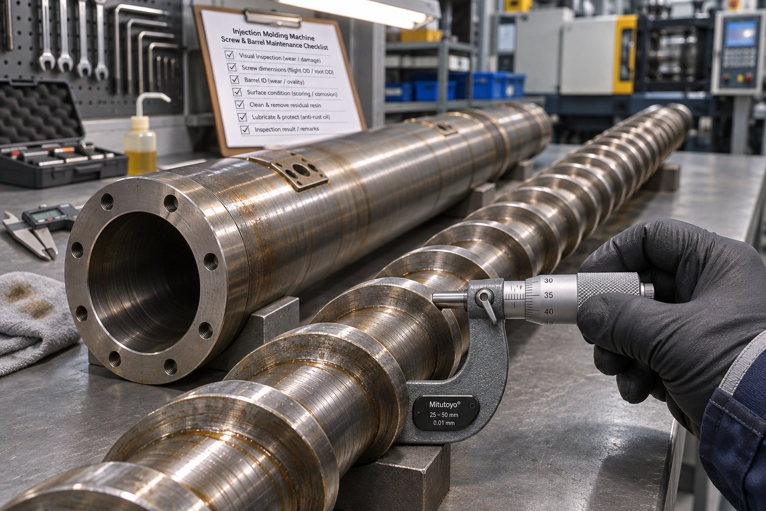
First Response Protocol and Preventive Maintenance Strategy
Defect interactions don't wait for convenient moments. They surface mid-run, mid-shift, sometimes mid-shipment deadline--and the response during those first few minutes determines whether the problem gets contained quickly or spirals into hours of lost production. Having a repeatable first-response protocol removes guesswork from that critical window. Pair it with a preventive maintenance strategy that keeps the process window from silently narrowing, and you've built a system that catches defects in plastic molding before they become crises rather than after.
The Five-Step First Response When a Defect Appears
When an operator spots a new quality issue--whether it's sink marks on an injection molded housing, splay streaking across a connector, or flash creeping along the parting line--the instinct is to start turning dials immediately. Resist that impulse. A disciplined diagnostic sequence, organized by cost-of-change hierarchy, resolves problems faster and avoids the overcorrection cascades described in the previous section.
- Confirm the defect is reproducible. Run several additional cycles and inspect the parts carefully. A single anomalous shot--caused by a momentary hydraulic fluctuation or a pellet bridging in the feed throat--doesn't warrant a full investigation. If the defect repeats across consecutive shots and appears in the same cavity location, it's a real trend. Note the cavity number, the defect position on the part, and the approximate cycle count when it first appeared.
- Compare current process parameters against the validated setup sheet. This step alone resolves a surprising percentage of mid-run quality events. Did someone bump melt temperature between shifts? Was cooling time shortened to meet a cycle-time target? Even a 3-degree barrel zone change or a 0.5-second hold-time reduction can push a borderline process over the edge. Process settings are free to adjust and instantly reversible--that's why they're checked first.
- Check material lot, hopper condition, and drying status. Verify that the resin grade and lot number match the validation records. Inspect the dryer's dew point reading--a dew point that has drifted upward from -40 degrees Celsius to -20 degrees Celsius can introduce enough moisture to cause splay in hygroscopic resins like nylon or polycarbonate. Confirm the regrind ratio hasn't crept above specification. Material checks are quick--usually under ten minutes--and catch one of the most common yet most preventable root-cause categories.
- Inspect the mold. Examine venting channels for blockage from off-gassing deposits, parting-line surfaces for wear or debris, cooling-line flow rates and temperature differential between supply and return, and ejector pins for proper stroke and alignment. Mold inspection requires some downtime, which is why it sits third in the sequence rather than first. But vents that were clean two days ago can accumulate enough residue to cause burn marks or short shots today, especially with resins that generate volatile byproducts.
- Examine plasticizing hardware. Check screw recovery time against baseline--if it's trending longer, the screw, barrel, or check ring may be wearing. Verify that the check-ring repeatability test shows stable cushion position. Review barrel temperature profile consistency across zones. Plastics Technology recommends pulling the screw at least once a year to inspect flight diameter, shank condition, and barrel inner diameter against manufacturer specifications. Hardware changes are the most involved corrective action, which is why they come last--but ignoring worn plasticizing components forces you to compensate endlessly with process adjustments that narrow your operating window over time.
This sequence mirrors the cost-of-change hierarchy that's been the backbone of every injection molding troubleshooting method in this guide. Process settings cost nothing to adjust. Material checks cost minutes. Mold inspection costs a press cycle or two of downtime. Hardware replacement costs real capital and extended downtime. Following this order ensures you exhaust the cheap, fast options before committing to expensive ones.
Preventive Maintenance That Reduces Defect Risk
Reactive troubleshooting handles the fire. Preventive maintenance keeps it from igniting in the first place. The most common defects in plastic molding--splay from poor drying, burn marks from clogged vents, flash from worn parting lines, inconsistent shot weight from degraded check rings--are all preventable with structured PM schedules. Yet many shops still follow what industry experts describe as a "run-parts-until-the-machine-breaks-down" approach, where unplanned maintenance events drive up costs, idle presses, and risk shutdowns at the customer.
Mold PM schedules should cover three high-impact areas on a recurring basis:
- Vent cleaning. Frequency depends on the resin--POM and flame-retardant compounds off-gas aggressively and may need vent cleaning every few thousand cycles, while clean-running resins like unfilled PP can go longer. Track burn-mark frequency as your trigger metric.
- Parting-line inspection. Check for wear, crushing, burrs, and debris accumulation. Stone the parting surfaces between mold changes to keep them flat. Mark any damaged areas for scheduled repair rather than running until flash becomes chronic.
- Cooling-line flushing. Scale buildup inside cooling channels reduces heat transfer gradually--so gradually that you may not notice until warpage or cycle-time drift becomes a problem. Annual descaling with a mild acid wash, combined with periodic flow-rate verification, keeps cooling performance consistent.
Plasticizing-unit monitoring is equally critical and far more commonly neglected. Screw and barrel wear develops slowly--so slowly that processors often compensate by adjusting temperature, pressure, or back pressure without realizing the underlying hardware is degrading. Common symptoms include inconsistent shot weight, unstable cushion position, longer plasticizing time, black spots from material degradation, and poor color mixing.
Key monitoring practices include:
- Screw recovery time trending. Record recovery time weekly under standardized conditions (same resin, same RPM, same back pressure). A gradual upward trend signals increasing clearance between screw flights and barrel wall.
- Shot-weight consistency checks. Weigh consecutive shots periodically. Variation beyond +/- 0.5% in precision applications--or +/- 1% in general molding--warrants a check-ring repeatability test to determine whether melt is leaking backward during injection.
- Barrel-liner wear measurement. During annual screw pulls, measure barrel bore diameter at multiple positions and compare against the manufacturer's specification. A barrel that's worn beyond tolerance will quickly destroy a newly installed screw, making the replacement ineffective.
Gradual screw and barrel wear often goes unnoticed until defects like inconsistent shot weight, splay, or black specks force an emergency investigation--by which time the damage has already cost weeks of marginal quality.
Matching Plasticizing Components to the Application
When screw-wear diagnosis reveals degraded plasticizing performance--longer recovery times, unstable cushion, material degradation--the temptation is to keep compensating with process adjustments. You increase back pressure to improve mixing, raise barrel temperatures to offset reduced shear heating, and extend purge cycles to manage black specks. These workarounds may buy time, but they simultaneously narrow the process window described in the previous section, making every other defect interaction harder to manage.
Replacing worn plasticizing components with properly specified hardware is more effective than indefinite compensation. The key word is "properly specified." A replacement screw and barrel should be matched to the actual resin being processed, the shot size relative to barrel capacity, and the specific defect history that prompted the change. A general-purpose screw geometry that worked adequately for unfilled ABS may be entirely wrong for a glass-filled nylon that demands better mixing, higher wear resistance, and a different compression ratio.
Suppliers like NANHAIYA offer custom injection molding screw barrels engineered around machine specifications, resin characteristics, and shot requirements. Their technical review process evaluates screw geometry, wear patterns, melting efficiency, mixing performance, and material-retention concerns to recommend a matched assembly--addressing the root hardware issues rather than treating symptoms through process offsets. This kind of application-specific approach to plasticizing components fits within a broader defect-prevention strategy that also includes mold maintenance, material handling discipline, and the structured troubleshooting hierarchy outlined throughout this guide.
No single component replacement eliminates all quality risk. But when the evidence points to worn or mismatched plasticizing hardware--and the diagnostic sequence has already ruled out process, material, and mold causes--investing in correctly specified screw and barrel components restores the process margin that keeps injection molded parts within specification, shift after shift.
Frequently Asked Questions About Injection Molding Defects
1. What are the most common injection molding defects?
The most frequently encountered injection molding defects include sink marks from differential shrinkage at thick sections, splay or silver streaks caused by moisture or shear, burn marks from trapped gas igniting under compression, flash where melt escapes at the parting line, short shots from incomplete cavity fill, warpage driven by uneven cooling or crystallization gradients, and black specks from degraded polymer fragments inside the barrel. Each defect traces back to one or more of four root-cause categories: process parameters, mold and tool design, material selection and handling, or part geometry. Identifying which category is responsible--and in what order to investigate--is the key to efficient troubleshooting.
2. Why does fixing one injection molding defect often cause another?
Every process parameter in injection molding--melt temperature, pack pressure, injection speed, cooling time--affects multiple quality outcomes simultaneously. For example, increasing pack pressure to eliminate sink marks also pushes harder against the parting line, risking flash, and forces the part to grip cores more tightly, increasing the chance of sticking. Lowering melt temperature to prevent burn marks raises viscosity, which can lead to short shots and weaker weld lines. These trade-off chains exist because defects share the same parameter space, and the acceptable range for one issue overlaps with the danger zone of another. A Defect Interaction Matrix helps engineers anticipate side effects before making adjustments, and Design of Experiments (DOE) methods systematically identify the optimal settings within the available process window.
3. How do you tell the difference between vacuum voids and gas bubbles in molded parts?
Although both appear as hollow spaces inside the wall, vacuum voids and gas bubbles have different causes and require different corrective actions. Vacuum voids form in thick sections when the solidified outer skin prevents the shrinking molten core from being fed by packing pressure--they tend to appear at rib roots, boss bases, and the thickest cross-sections. Gas bubbles result from moisture, volatile additives, entrained air, or thermal degradation and can appear randomly throughout the part. A practical shop-floor test involves slowly heating the defect area with a heat gun: a vacuum void collapses into a sink mark, while a gas bubble expands. Correcting voids focuses on pack pressure, hold time, and gate sizing, whereas bubbles require addressing the upstream gas source--typically resin drying, barrel temperature, or dead spots in the plasticizing unit.
4. How do different resin types affect which defects are most likely?
Resin family is one of the strongest predictors of defect susceptibility. Semi-crystalline polymers like PP, PA (nylon), POM, and HDPE shrink significantly more--and more directionally--than amorphous resins like ABS, PC, or PMMA. This makes semi-crystalline materials far more prone to warpage and sink marks. Amorphous resins, with their lower uniform shrinkage, are more susceptible to stress cracking and shear-related surface defects like splay. Moisture-sensitive resins such as PC, nylon, and PC/ABS blends demand rigorous drying to prevent splay. Glass-filled compounds add anisotropic shrinkage from fiber orientation, increased wear on screws and barrels, and weakened weld lines. Matching your troubleshooting approach to the specific resin family avoids wasting time on low-probability causes.
5. When should you stop production because of an injection molding defect?
The decision depends on defect severity. Cosmetic defects that fall within the customer's acceptance specification can be documented while production continues at increased sampling frequency. Cosmetic defects outside specification but not worsening may warrant a minor process adjustment within the validated window--if the issue resolves within a defined number of shots, normal production resumes. Structural defects--internal voids, weak weld lines, stress marks--require an immediate halt, quarantine of suspect parts, and a root cause investigation before restarting, because these issues rarely self-correct and risk shipping compromised parts. Functional failures like short shots, severe warpage, or flash preventing assembly demand an instant stop since they signal a fundamental breakdown that process tweaks alone are unlikely to resolve. Having these criteria documented in a control plan before production starts removes ambiguity across shifts.
Written by
Nanhaiya Technical Team
Zhoushan Nanhaiya Plastic Machinery Co., Ltd.
The Nanhaiya technical team supports screw and barrel manufacturing projects through application review, technical communication, custom manufacturing coordination, and production and quality control.
Discuss Your Application
Related Articles
More insights on screw barrel technology and plastics processing.

Injection Molding Color Mixing: From Streaks to Flawless Consistency
Nov 19, 2026
Master injection molding color mixing with expert guidance on colorant types, screw design, process parameters, defect troubleshooting, and Delta E QC protocols.
Read Article
Wrong Extruder Breaker Plate? Spot the Signs Before Scrap Piles Up
Nov 19, 2026
Learn how to select, size, and maintain your extruder breaker plate. Covers hole geometry, pressure drop, polymer-specific specs, and troubleshooting tips.
Read Article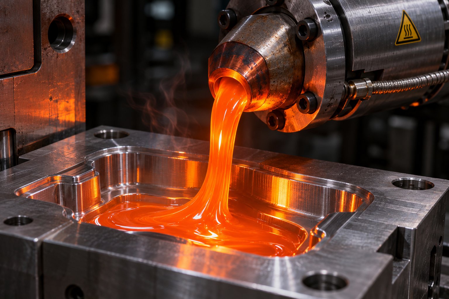
Injection Molding Melt Temperature: Why Your Barrel Settings Lie
Nov 19, 2026
Learn why barrel set points lie about injection molding melt temperature. Complete resin chart, measurement methods, defect troubleshooting, and optimization steps.
Read ArticleLooking for something else?
Search by material, symptom or product and jump straight to the relevant page.
These are navigation suggestions based on keyword matching — not a quotation, not a delivery commitment, and not a substitute for engineering review. Final specification is confirmed by our engineers against your drawings and processed material.
Need help with screw barrel selection?
Share your machine model, processed material and application. Our team can help with pricing and technical support.