

What Is Injection Molding Flash and Why Does It Matter
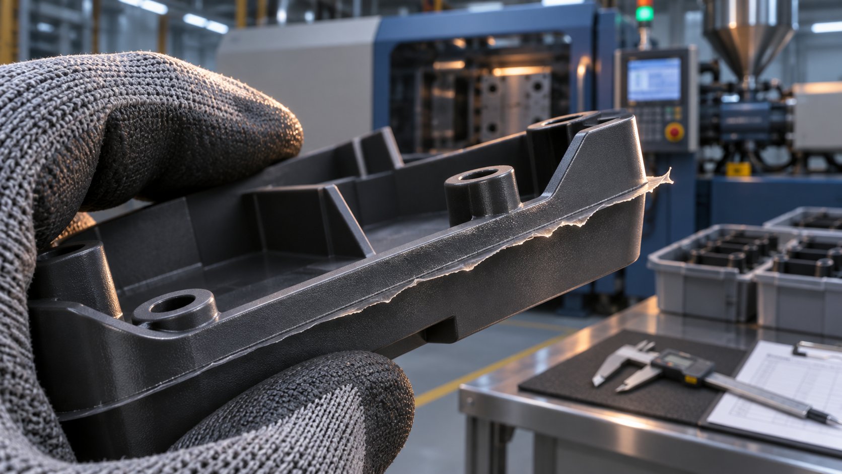
Imagine pulling a freshly molded part from the press and running your finger along its edge — only to feel a thin, razor-like fin of excess plastic extending beyond the intended geometry. That unwanted material is flash, and it ranks among the most persistent headaches in plastic manufacturing. Whether you call it flashing, flashed edges, or simply burrs, the defect signals that molten resin escaped the mold cavity where it did not belong.
Defining Flash in Plastic Injection Molding
Injection molding flash is a thin layer of excess plastic that escapes the mold cavity at parting lines, ejector pin interfaces, vents, or other mold component boundaries, then solidifies as an unwanted protrusion on the finished part.
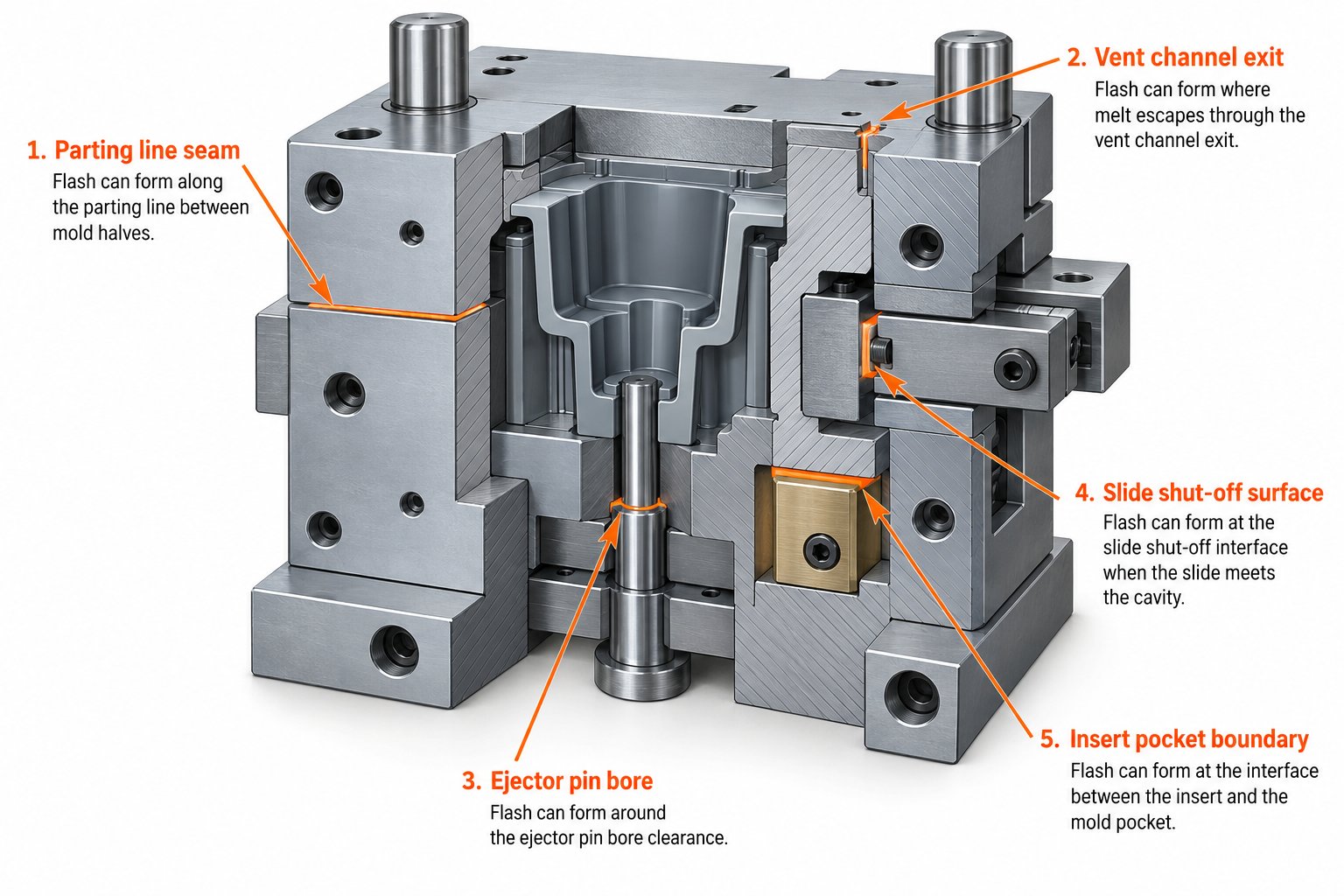
Flash forms when molten resin finds a gap — however small — between surfaces that should seal tightly. These gaps can appear at the parting line where the two mold halves meet, around ejector pins, along slide shut-offs, or at any steel-to-steel interface within the tool. The industry-accepted threshold for mold flash is generally less than 0.004 in. (0.10 mm); anything beyond that often demands corrective action. Achieving flash levels at or below 0.002 in. (0.05 mm) is possible but requires tighter tooling tolerances and more disciplined process control.
Why Flash Is More Than a Cosmetic Problem
At first glance, a thin sliver of plastic seems harmless. In reality, it quietly drives up costs and erodes quality across four dimensions:
- Part aesthetics: Visible flash on consumer-facing surfaces creates an impression of poor quality, much like a metallic flash or burr would on a die-cast or flash casting part.
- Dimensional accuracy: Even a few thousandths of an inch of excess material can push a critical dimension out of tolerance, especially in tight-fitting assemblies.
- Assembly fit: Flash along sealing surfaces or mating edges interferes with part seating, gasket compression, and snap-fit engagement.
- Downstream costs: Every flashed part that requires trimming, rework, or rejection adds labor, scrap, and cycle time to the production equation.
It is worth noting what flash is not. Sink marks — depressions on the part surface — result from insufficient packing in thick sections, not from material escaping the cavity. Short shots leave sections of the part unfilled, the exact opposite of flash. Weld lines appear where two flow fronts meet and fail to fuse completely, creating a visible seam but no excess material. If you see excess plastic extending beyond the intended part boundary, you are dealing with flash.
How This Guide Is Organized
Most troubleshooting resources treat flash as a single problem with a flat list of possible fixes. This guide takes a different approach. You will work through a dual-axis framework that classifies the defect by where it appears on the part — parting line, vent channel, ejector pin, slide interface, or insert boundary — and by why it formed, grouped into four root cause categories: pressure-related, mold-condition-related, material-related, and process-related factors. Each category reveals different diagnostic paths and different corrective actions.
The sections ahead begin by mapping the five distinct flash types you are likely to encounter on the shop floor — each with a unique visual signature and a primary cause that points your investigation in the right direction.
Five Types of Flash by Location and Their Distinct Causes
Telling a mold tech "the part has flash" is a bit like telling a mechanic "the car makes a noise." The fix depends entirely on where the problem shows up — and a thin fin along the parting line points to a completely different root cause than a ring of material around an ejector pin witness. Precise language saves troubleshooting time, so let's build a classification system around five flash types defined by their physical location on the molded part.
Parting Line Flash
Parting line flash is by far the most common variety. It appears as a continuous or semi-continuous thin fin running along the seam where the cavity and core halves of the mold meet. You will typically spot it tracing the entire perimeter of the part, though it can be heavier on one side if platen parallelism is off or if the cavity pressure distribution is uneven.
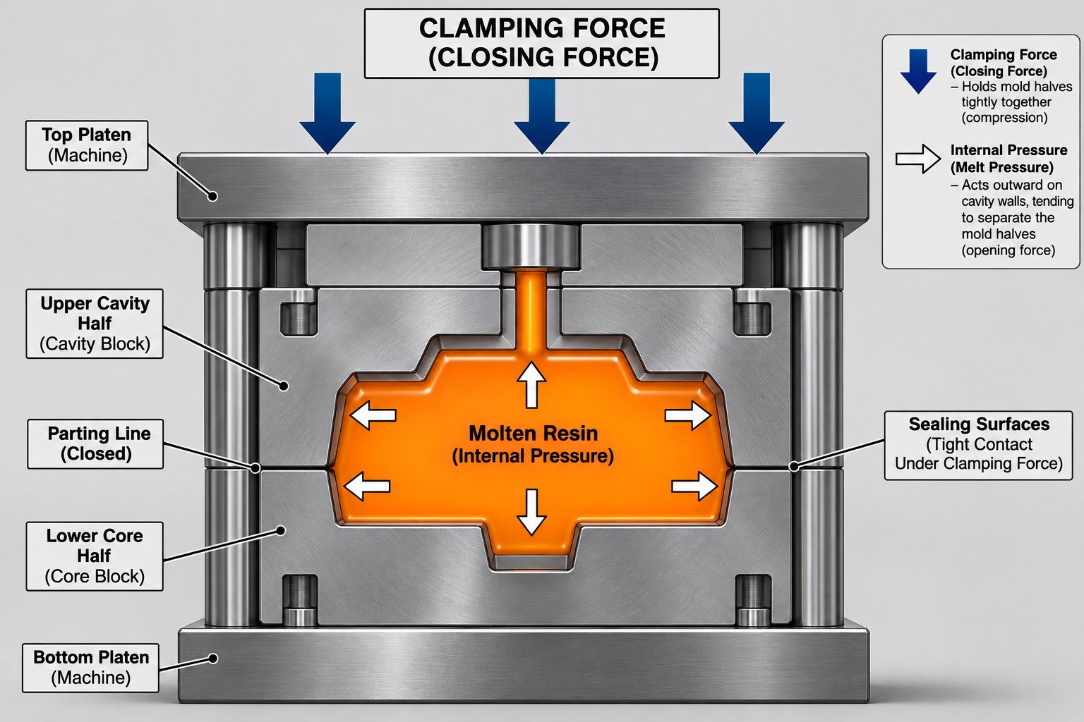
The mechanism is straightforward: during injection and packing, the melt pressure inside the cavity pushes outward against the mold steel. If the clamp force is insufficient to resist that internal pressure, the mold halves separate by just a few thousandths of an inch — enough for low-viscosity resin to escape. Worn or damaged parting surfaces produce the same effect without any clamp deficiency at all; the steel simply no longer seals. Contamination trapped on the parting face — a stray pellet, a sliver of flash from a previous cycle, or residual purge material — can also prevent full mold closure and generate a localized gap.
When you see flash evenly distributed along the parting line, start your investigation with clamp tonnage and projected area. If the flash is isolated to one section, shift your attention to the mold steel itself: look for wear, damage, contamination, or deflection in that specific zone.
Vent and Ejector Pin Flash
Vent flash shows up as thin, delicate wisps of material at the very end of vent channels — those shallow, precision-machined grooves that allow trapped air to escape during filling. Every resin has a maximum vent depth that permits air evacuation without letting the melt itself squeeze through. When vents are cut too deep, become worn, or get damaged during maintenance, plastic follows the air right out of the cavity. The visual signature is distinctive: fine, hair-like strands or paper-thin tabs at the vent location, sometimes so small they go unnoticed until they break off and appear as contamination on downstream parts.
Your first diagnostic step with vent flash is simple: measure the actual vent depth with a depth micrometer or optical comparator and compare it against the resin manufacturer's recommended limit. Vents gradually deepen over thousands of cycles due to steel erosion — especially with abrasive glass-filled resins — so a channel that was within spec at mold build may have drifted out of tolerance months later.
Ejector pin flash, on the other hand, appears as a raised ring or halo around each pin witness mark on the part. Imagine a tiny volcano rim surrounding the flat circular area left by the pin. This occurs when the bore in the mold that guides the ejector pin wears oversize, or when the pin itself becomes undersized from repeated cycling. The resulting annular gap between pin and bore acts as an escape route for pressurized melt during the packing phase.
Diagnosing ejector pin flash calls for inspection of pin-to-bore clearance. Replace worn pins, ream bores back to spec, or consider upgrading to a tighter-tolerance pin-and-bushing system in problem areas. If flash appears at only a few pin locations rather than all of them, uneven cavity pressure or localized overpacking near those pins is likely contributing.
Slide, Lifter, and Insert Interface Flash
Complex part geometries often require moving mold components — slides that form undercuts, lifters that release internal features — and each one introduces a shut-off surface where steel meets steel under pressure. Flash at these interfaces typically appears as a thin fin or ridge along the boundary of the feature the action component forms. It may follow the leading edge of a slide shut-off or trace the perimeter where a lifter contacts the cavity block.
The primary cause is mechanical: insufficient contact, wear, misalignment, or inadequate support in the action component. Unlike parting line flash that responds to global clamp force adjustments, slide and lifter flash is a local tooling condition. Increasing clamp tonnage will not fix a worn heel block or a lifter that has shifted off its guided path. Diagnosis starts with a physical inspection of the shut-off surfaces and the mechanical components that lock slides and lifters into position during injection.
Insert flash deserves its own attention because the sealing challenge is fundamentally different. In insert molding and overmolding operations, a pre-placed component — metal stamping, brass bushing, circuit board, or a previously molded substrate — sits inside the mold while plastic is injected around it. Flash occurs where the insert contacts the mold steel if dimensional tolerances on the insert or the mold pocket allow a gap. Since insert tolerances of +/-0.05 mm or tighter are common targets, even slight variation in stamped metal parts can open an escape path for the melt. Mismatched insert tolerances or steel deflection under packing pressure are frequent culprits. The diagnostic direction here involves measuring the actual insert dimensions against the mold pocket, checking that the insert seats consistently, and verifying that clamping force profiles adequately support the interface during packing.
| Flash Type | Typical Location | Visual Signature | Primary Cause Category | First Diagnostic Step |
|---|---|---|---|---|
| Parting Line Flash | Seam where cavity and core halves meet | Continuous or semi-continuous thin fin along part perimeter | Clamp force deficiency, worn or damaged parting surfaces, contamination | Compare actual clamp tonnage to projected area requirement; inspect parting surface condition |
| Vent Flash | End of vent channels at cavity edge | Fine, hair-like wisps or paper-thin tabs at vent exits | Vent depth exceeds resin flash-free limit due to wear or improper machining | Measure vent depth against resin supplier's recommended maximum |
| Ejector Pin Flash | Around ejector pin witness marks on part surface | Raised ring or halo encircling each pin witness | Worn pin bores or undersized pins creating annular clearance | Inspect pin-to-bore clearance; replace worn pins or ream bores |
| Slide/Lifter Flash | Along shut-off edges of slides, lifters, or action components | Thin ridge or fin tracing the boundary of the undercut feature | Wear, misalignment, or insufficient support in action components | Physically inspect shut-off surfaces and locking mechanisms |
| Insert Flash | Interface between pre-placed insert and mold steel pocket | Thin flash ring around insert perimeter or along metal-to-steel boundary | Insert dimensional variation, pocket tolerance mismatch, steel deflection | Measure insert dimensions against mold pocket; verify seating consistency |
Each of these five flash types responds to different corrective actions, and misidentifying the type almost guarantees wasted effort. A molder who reduces pack pressure to address what is actually a worn ejector pin bore may eliminate the flash temporarily — but will also under-pack the part, introducing sink marks and dimensional drift. Accurate classification is the first step toward a targeted fix rather than a process band-aid.
Of course, classification by location only tells you where material is escaping. The deeper question — why the process is pushing melt into those gaps in the first place — requires a close look at the injection parameters that generate and control cavity pressure throughout the molding cycle.
Process Parameters That Cause and Control Flash in Injection Molding
Cavity pressure is the driving force behind every flash defect — but cavity pressure itself is the product of multiple process settings working together. Adjusting one parameter in isolation often just shifts the problem elsewhere. To truly control flash, you need to understand how each setting contributes to the pressure that forces melt into gaps, and more importantly, how those settings interact with each other.
A useful mental benchmark: most parting-line gaps in the range of 0.001 to 0.005 inches (0.025 to 0.127 mm) are enough for molten resin to penetrate and form visible flash. The exact threshold depends on the resin's viscosity and the pressure behind it — two variables that your process parameters directly govern.
Injection Speed, Pressure, and Switchover Timing
Imagine filling a balloon with a high-pressure air hose. The faster and harder you push, the more likely the balloon will find a weak spot and rupture. The same principle applies inside a mold cavity. Excessive injection speed generates dynamic pressure spikes — especially near the end of fill when the cavity is nearly full and the melt has nowhere left to go. Those spikes can momentarily exceed the clamp force holding the mold shut, opening the parting line just long enough for material to escape.
Injection pressure itself is the direct force pushing polymer into the cavity. When it exceeds what the clamping system can resist across the projected area, the mold halves separate. Reducing injection pressure in 5% increments while monitoring the parting line is a common diagnostic step for pressure-related flash.
The switchover point — where the machine transitions from velocity-controlled filling to pressure-controlled packing — is arguably the most underappreciated flash trigger. A late switchover means the screw is still driving forward under velocity control when the cavity is nearly or completely full. The result? A sudden pressure spike that can force material into every available gap. As John Bozzelli of Injection Molding Solutions explains, spikes or a gradual slide into second-stage pressure at switchover will overpack the cavity and may cause flash. The transition from first to second stage should occur in less than 0.10 seconds for proper process control, and the machine response should be clean — no dips, spikes, or oscillations. If your switchover occurs too late, the cavity experiences a pressure surge before the machine even begins regulating pack pressure, and that surge is often the hidden culprit behind intermittent flash that seems to come and go without explanation.
Pack and Hold Pressure as the Primary Flash Lever
If injection speed and switchover timing create the initial pressure event, pack and hold pressure sustains it. This second-stage pressure pushes additional material into the cavity to compensate for volumetric shrinkage as the part cools. Set it too high or hold it too long, and you are effectively forcing melt past every interface in the tool — parting lines, vent channels, ejector pin bores, and slide shut-offs.
Here is what makes pack pressure especially tricky: it acts on the part after the cavity is already full. Every pound of force applied during packing has nowhere constructive to go once the part volume is satisfied — it simply pressurizes the melt against every sealing surface in the mold. Excessive hold pressure applied after the gate has already frozen accomplishes nothing except forcing material through any unsealed interface. A gate freeze-off study — where you incrementally increase hold time and weigh the parts — helps you identify the exact moment the gate seals so you can avoid over-pressurizing beyond that point.
The Scientific Molding approach recommends establishing hold pressure empirically: start low, increase in small increments, and let the part's dimensional response and quality data guide you to the correct setting rather than relying on rules of thumb like "use 50% of injection pressure." That myth, as Bozzelli notes, has no data for support.
Melt and Mold Temperature Interactions
Temperature does not create flash on its own — but it dramatically changes how much pressure the process can tolerate before flash appears. Higher melt temperatures reduce resin viscosity, allowing the polymer to flow more easily into gaps that a cooler, stiffer melt would not penetrate. Think of it like the difference between honey and water: pour both toward a small crack, and you'll notice which one finds its way through.
Mold temperature amplifies this effect at the critical location — the parting surface itself. A hotter mold keeps the melt fluid longer near the sealing interfaces, extending the window during which pressurized resin can escape. This is why flash sometimes appears only after the mold reaches thermal equilibrium during a production run, even though the process seemed stable during initial setup when the tool was still cold.
The interactive relationship between temperature and pressure is what makes flash injection molding troubleshooting genuinely complex. The same pack pressure that produces perfect parts at a 410 degree F melt temperature may cause heavy flash at 430 degrees — because the viscosity drop at the higher temperature allows the melt to penetrate gaps that were previously sealed by the resin's own resistance to flow. Conversely, a molder who lowers melt temperature to combat flash may inadvertently create short shots or poor surface finish, trading one defect for another.
Ranking these parameters by their typical impact on flash formation gives you a practical prioritization for troubleshooting. When flash appears, work through these levers in order:
- Pack and hold pressure: The most direct lever. Excessive pack pressure is the single most common process-side cause of flash. Reduce it first and observe the response.
- Switchover point: A late or inconsistent transition from fill to pack creates uncontrolled pressure spikes that overpack the cavity before second-stage settings even take effect.
- Injection speed: High velocity generates dynamic pressure surges at end of fill. Profiling speed with a slow-fast-slow ramp can reduce peak pressure without sacrificing fill quality.
- Melt temperature: Higher temperatures reduce viscosity and lower the pressure threshold at which flash begins. Verify thermocouple calibration and check all barrel zone settings.
- Mold temperature: Contributes indirectly by keeping the melt fluid longer at parting surfaces. Rarely the primary cause alone, but a meaningful amplifier when combined with elevated melt temperature or marginal clamping.
The key takeaway? These parameters do not act in isolation. A process that is borderline on pack pressure may run flash-free until a new resin lot arrives with a slightly higher melt flow index — and suddenly the same settings produce unacceptable flash. Or a mold that has been running cleanly for months begins flashing after a temperature controller drifts upward. Understanding these interactions helps you diagnose the real trigger rather than chasing symptoms from one parameter adjustment to the next.
That sensitivity to resin behavior raises an important question: if the same process settings produce flash with one material but not another, how much does the plastic itself contribute to the problem? Quite a lot, as it turns out — and specific resin families carry dramatically different flash risks based on their viscosity, moisture sensitivity, and filler content.
How Resin Properties and Material Selection Influence Flash
You could have a perfectly maintained mold, ideal clamp tonnage, and a textbook-clean process setup — and still fight flash every shift. The missing variable? The plastic itself. Resin viscosity, melt flow index, moisture sensitivity, and filler content all shape how aggressively a material seeks out gaps in the tool. Two resins processed on the same machine with identical settings can produce dramatically different flash results, and understanding why is essential to diagnosing problems that process adjustments alone cannot solve.
Viscosity and Melt Flow Index Effects on Flash
Viscosity is the property that determines how readily molten plastic flows under pressure. A low-viscosity resin behaves almost like water — it finds every crack, seam, and microscopic opening in the mold. A high-viscosity resin resists that movement, acting more like thick syrup that cannot squeeze through a narrow gap before it freezes off.
The industry shorthand for this behavior is Melt Flow Rate (MFR), sometimes called Melt Flow Index (MFI). This standardized test — governed by ASTM D1238 and ISO 1133 — measures how many grams of polymer extrude through a specified orifice in ten minutes under a set load and temperature. A higher MFR number means easier flow, which translates directly to greater flash susceptibility. High-MFR polyethylenes designed for thin-wall packaging, for instance, can penetrate parting-line gaps that a stiffer polycarbonate would never enter.
Consider the practical impact. Nylon (PA6 and PA66) is notoriously flash-prone because its low melt viscosity allows it to seep into gaps as small as 0.0005 inches. Certain high-flow polypropylene grades used for thin-wall containers share the same tendency. On the opposite end, polycarbonate and ABS carry higher viscosities that naturally resist flash — but they demand elevated injection pressures to fill the cavity, which stresses the mold and clamp system in a different way. The tradeoff is real: resins that resist flash often require more force to mold, and that extra force can accelerate mechanical wear on parting surfaces over time.
The width of a resin's processing window matters just as much as its baseline viscosity. Some materials — POM (acetal) is a good example — have a narrow temperature range between proper flow and degradation. Operating near the upper end of that window for fill quality means you are also running at the lowest viscosity the resin offers, increasing flash risk. Resins with wider processing windows give you more room to dial back temperature and tighten viscosity without sacrificing part quality.
Hygroscopic Resins and Moisture-Driven Viscosity Shifts
Here is where intermittent, seemingly random flash often finds its explanation. Hygroscopic resins — nylon being the prime example — absorb moisture from the surrounding air. That moisture does not just sit inertly inside the pellet. During melting, water molecules act as a plasticizer, breaking polymer chains through a chemical reaction called hydrolytic degradation. The result is a measurable drop in molecular weight, a corresponding reduction in melt viscosity, and a resin that flows far more easily than its data sheet predicts.
Imagine running a nylon job that has been flash-free for hours. Midway through the shift, the hopper dryer malfunctions or the desiccant becomes saturated. Moisture content in the pellets creeps above the recommended window — typically 0.02% to 0.20% for unfilled PA — and suddenly parts start flashing at the parting line. The process settings have not changed. The mold has not changed. But the resin's effective viscosity has shifted downward just enough to penetrate gaps that were previously sealed.
This scenario is more common than most production floors realize, and it explains why monitoring moisture content is not just a quality-control nicety — it is a flash prevention strategy. Performing moisture checks every two to four hours during nylon production, as recommended by material suppliers, helps catch viscosity drift before it manifests as defective parts.
How Filled Resins Accelerate Mold Wear and Flash
Glass-filled and mineral-filled resins introduce a different flash mechanism entirely: progressive mold degradation. Glass fibers, in particular, are highly abrasive. Every shot cycle pushes fiber-laden melt across parting surfaces, vent channels, and shut-off faces at high velocity and pressure. Over thousands of cycles, this abrasion erodes the very steel surfaces that create the seal keeping material inside the cavity.
Zach Hanson, IM applications engineering manager at Protolabs, put it clearly: "Filled materials will also wear mold parting lines faster and can cause flash to appear quicker as the tool wears." A mold running unfilled ABS might maintain its parting-line seal for hundreds of thousands of shots. The same mold running 30% glass-filled nylon could begin showing flash in a fraction of that cycle count as the steel edges round over and gaps develop.
The insidious aspect is that this flash develops gradually. Production starts clean, and over weeks or months, technicians begin nudging pack pressure down or reducing melt temperature to compensate — classic band-aid adjustments that mask the underlying wear while introducing other quality issues. Recognizing that the root cause is mechanical wear rather than a process drift changes the corrective action entirely: the mold needs refurbishment, not another process tweak.
| Resin Family | Relative Viscosity | Flash Tendency | Key Processing Notes |
|---|---|---|---|
| Nylon (PA6, PA66) | Low | High | Hygroscopic — moisture lowers viscosity further; glass-filled grades accelerate mold wear; monitor drying closely |
| Polyethylene (PE — HDPE, LDPE) | Low to Medium (varies with MFR) | Medium to High | High-MFR injection grades are very flash-prone; HDPE grades with lower MFR resist flash better |
| Polypropylene (PP) | Low to Medium | Medium to High | High-flow thin-wall grades are especially susceptible; wider processing window than nylon |
| Polycarbonate (PC) | High | Low | Requires elevated injection pressure to fill, stressing mold and clamp; sensitive to moisture but less so than nylon |
| ABS | Medium to High | Low to Medium | Relatively forgiving; good balance of flow and flash resistance; amorphous structure provides a wide processing window |
| POM (Acetal) | Medium | Medium | Narrow processing window; sensitive to overheating which drops viscosity; crystalline structure can cause sharp viscosity transitions |
The takeaway for process engineers is clear: your resin selection has already determined a significant portion of your flash risk before the machine ever starts cycling. A material with a high melt flow index and moisture sensitivity demands tighter mold tolerances, more rigorous drying protocols, and a narrower process window to stay flash-free. Ignoring material-specific tendencies and relying solely on process adjustments is a recipe for chasing the defect indefinitely.
Material behavior, however, only explains what the plastic wants to do. Whether it actually escapes the cavity depends just as much on how the mold was designed — from the clamp tonnage calculation and projected area ratio to the geometry of slides, lifters, and venting channels that either contain the melt or quietly invite it to leak.
Mold Design Factors That Create Flash Vulnerabilities
A mold can be brand new, freshly polished, and built to print — and still flash on the very first shot. Why? Because the decisions made during mold design lock in the tool's vulnerability to flash long before resin ever touches steel. Clamp tonnage ratios, cavity layouts, shut-off geometries, venting depths, and even the grade of steel selected for the parting surfaces all shape whether a mold will seal reliably or quietly invite mold flash into every production run.
Clamp Tonnage, Projected Area, and Cavity Pressure
Every injection molding flash discussion eventually comes back to one fundamental question: does the machine have enough force to keep the mold shut against the internal pressure trying to push it open? The answer depends on three variables — projected area, cavity pressure, and clamp tonnage — and their relationship is governed by a straightforward formula:
Required Tonnage = Projected Area (in2) x Clamp Factor (tons/in2) x Safety Factor
Projected area is the "shadow" of the part and runner system viewed from the clamping direction — not the total surface area of the part. A flat, wide cover has far more projected area than a tall, narrow tube, even if both weigh the same. The clamp factor captures how much pressure the resin and part geometry will generate inside the cavity. According to JeekMould's engineering guidelines, practical clamp factors range from 2 to 3 tons/in2 for easy-flow materials and simple geometries, up to 5 to 7 tons/in2 for thin-wall, long-flow, or glass-filled applications. A safety factor of 1.1 is commonly applied to account for material variation and process fluctuations.
Consider a quick example: a four-cavity mold with each part projecting 12 in2 and a runner system adding 8 in2 yields a total projected area of 56 in2. At a clamp factor of 4 tons/in2 and a 1.1 safety factor, you need roughly 246 tons of clamping force. Run that mold on a 200-ton press and you will be seeing flashing on the parting line before the first box of parts is packed — not because the mold is poorly built, but because the machine simply cannot hold it closed.
Multi-cavity layouts amplify this risk rapidly. A single-cavity mold for the same part might comfortably fit a 60-ton press, but doubling or quadrupling the cavities does not just double the projected area — it also adds runner area and increases the total force the clamp must resist. Mold designers who do not recalculate tonnage for every cavity count option risk specifying a tool that exceeds the available machine capacity on the production floor.
Complex Mold Geometries — Slides, Lifters, and Core Shift
Flat parting lines at least have the advantage of full clamp force pressing evenly across the sealing surface. Complex mold geometries introduce entirely different failure modes. Slides, lifters, and angled shut-offs create localized interfaces where the sealing force depends not on the machine's main clamp but on mechanical locks, heel blocks, and angled surfaces — components that wear, loosen, and shift over time.
Core shift is a particularly sneaky contributor to flash. When cavity pressure is not balanced symmetrically around a core, the hydraulic force of the melt can physically push the core to one side. The result? The gap on the high-pressure side closes tighter while the opposite side opens — creating flash on one side and a thicker wall section on the other. You might not notice the wall thickness shift on a standard inspection, but the flash on the parting line tells the story. Unbalanced gating, asymmetric part geometry, and inadequate core support all contribute to this problem.
Multi-cavity mold imbalance produces a related issue at a macro level. If runner lengths or gate sizes are not perfectly balanced, some cavities fill and pack before others. The early-packing cavities experience higher internal pressure, which can cause localized mold separation — flash in some cavities while others simultaneously produce short shots. Geometrically balanced runner systems (where all flow paths are equal in length and cross-section) help, but real-world conditions like shear-induced viscosity variations in runner bends can still create subtle imbalances that manifest as selective flash.
Venting depth deserves special attention in this context. Every mold needs vents to evacuate air during filling, but each resin has a flash-free vent depth threshold — the maximum groove depth that allows air to escape without letting melt follow. When a technician encounters a burn mark or short shot caused by trapped gas, the temptation is to deepen the vents. Cut past the resin's limit and you have traded one defect for another: the burn mark disappears, but vent flash takes its place. Maintaining a vent depth log and verifying dimensions against the resin manufacturer's specifications prevents this common overcorrection.
How Mold Steel Selection Affects Long-Term Flash Performance
The steel a mold is built from determines how long its parting surfaces will maintain a flash-free seal. Not all tool steels offer the same wear resistance, and the gap between them becomes significant over hundreds of thousands of cycles — especially with abrasive filled resins.
- P20 steel is the workhorse for low- to medium-volume production. Pre-hardened and easy to machine, P20 works well with commodity resins like polypropylene and polyethylene. However, its lower wear resistance means parting surfaces erode faster when processing glass-filled or mineral-filled materials, progressively worsening flash over the tool's life.
- H13 steel steps up with excellent wear resistance and thermal fatigue resistance, making it the go-to choice for high-volume tools and abrasive plastics. H13 can be heat-treated to 50-60 HRC, allowing parting-line edges to hold their geometry far longer than P20 under demanding conditions.
- S7 steel offers a unique combination of toughness and impact resistance, making it ideal for slides, lifters, and other action components that experience repeated mechanical contact. At a typical working hardness of 54-56 HRC, S7 resists the battering that gradually loosens shut-off fits and creates flash at moving interfaces.
Choosing P20 for a mold that will run 30% glass-filled nylon at high volumes is an invitation for progressive mold flash: the tool will start clean and gradually deteriorate as fiber abrasion erodes the parting surfaces. Specifying H13 or S7 for critical sealing surfaces costs more upfront but protects the seal integrity that keeps flash at bay across the tool's full production life.
Flash Challenges in Overmolding, Insert Molding, and Micro-Molding
Specialized molding processes introduce sealing challenges that standard parting-line design rules do not fully address.
Overmolding requires the second-shot material to flow around a previously molded substrate without escaping the seal between that substrate and the mold steel. The substrate's dimensions after cooling and shrinkage must match the second-shot cavity precisely. If the substrate shrinks more than expected, the seal loosens and flash appears along the substrate boundary. Substrate material consistency, cooling time, and dimensional verification between shots are all critical controls.
Insert molding faces a similar challenge with metal or non-polymer inserts. A stamped metal bracket placed into the mold must seat against the steel pocket with minimal clearance — yet stamping tolerances, burrs, and slight warpage all introduce variability. As Protolabs notes, flash is common anywhere metal meets metal inside the mold, and insert interfaces are no exception. Tight pocket tolerances and incoming inspection of insert dimensions help control this variable, but zero-flash insert molding often demands fixture-level precision that drives tooling cost upward.
Micro-molding magnifies flash into a proportionally massive defect. When the finished part weighs fractions of a gram and features measure in hundreds of microns, even a micron-level gap at the parting surface produces flash that is significant relative to the part geometry. Mold tolerances must be held to single-digit micron levels, and any wear that would be negligible in a standard tool becomes functionally unacceptable. Micro-mold builders often use hardened tool steels exclusively and schedule far more frequent parting-line inspections than conventional mold maintenance programs call for.
Each of these specialized applications reinforces the same principle: flash prevention begins in the design phase. A mold that is undersized for the press, built from the wrong steel, or designed with insufficient attention to shut-off geometry will flash regardless of how carefully the process is tuned. Yet even a well-designed tool will eventually flash if the team lacks a structured method for diagnosing whether the root cause is pressure, mold condition, or material — a decision-tree approach that separates systematic troubleshooting from trial-and-error guesswork.
A Step-by-Step Diagnostic Flowchart for Troubleshooting Flash
Knowing what causes flash and recognizing where it appears are essential foundations — but they do not tell you what to do first when parts start flashing mid-run and the clock is ticking. Most troubleshooting guides hand you a flat list of possible causes and leave you to guess which one applies. That approach wastes time, material, and patience. What process engineers actually need is a branching decision path — a structured sequence of questions where each answer narrows the field and directs the next action. The diagnostic flowchart below does exactly that, combining pressure-focused analysis with mold condition and material checks so you isolate the root cause instead of chasing symptoms.
Is the Flash Consistent or Isolated
Your very first observation splits the investigation into two fundamentally different directions. Pull five to ten consecutive shots and examine every cavity, every parting surface, every ejector pin witness. Ask one simple question: does the flash appear across all cavities and locations, or is it confined to a specific cavity or region?
- Flash is consistent across all cavities and the full parting line.
- This pattern points toward a global cause — something affecting the entire mold equally. Insufficient clamp tonnage, excessive pack pressure, elevated melt temperature, or a late switchover are the most likely culprits. Move to the pressure-side diagnostic branch below.
- Flash is isolated to one cavity, one region, or one specific mold interface.
- Isolated flash signals a local tooling issue: parting-line damage in that zone, a worn ejector pin bore, a misaligned slide, or a vent cut too deep at that location. A process change would not produce flash in just one spot while leaving the rest of the mold clean. Move to the mold-side diagnostic branch.
This single observation eliminates roughly half the possible causes before you touch a single machine setting. As MBPlastiPro's diagnostic guide puts it: flash on every cavity all around the parting line points to a global force problem, while flash in one cavity or one region only points to local tooling wear or deformation.
Sudden Onset Versus Gradual Worsening
The second branch refines your timeline. Think about when the flash first appeared — was it a sudden event or a slow escalation?
- Flash appeared suddenly — parts were clean last shift, and now they are flashing.
- Sudden onset suggests an abrupt change in the system. Common triggers include:
- A process parameter that was altered (intentionally or accidentally) between runs
- A broken or cracked mold component — a heel block, a slide lock, or a support pillar
- A part that stuck in the mold during ejection, preventing full closure on the subsequent cycle and damaging the parting surface
- A clamp system malfunction — hydraulic pressure loss, toggle wear, or tie-bar stretch exceeding limits
- Action: compare the current process setup sheet against the validated settings. Inspect the mold for visible damage. Check clamp pressure readings before adjusting anything else.
- Sudden onset suggests an abrupt change in the system. Common triggers include:
- Flash has been worsening gradually over weeks or months.
- Gradual onset is the hallmark of progressive wear. Parting surfaces erode, vent channels deepen from abrasion (especially with glass-filled resins), ejector pin bores enlarge, and slide shut-offs loosen incrementally. The process settings that kept flash at bay six months ago simply can no longer compensate for the growing gaps in the tool.
- Action: schedule a parting-line inspection and measurement. Resist the temptation to further reduce pack pressure or melt temperature as a workaround — those band-aids mask the real problem and introduce new defects like sink marks or dimensional drift.
Pressure, Mold, and Material Diagnostic Branches
With pattern and timeline established, you are ready to dive into the specific diagnostic category your earlier answers pointed toward. Work through the relevant branch below, changing one variable at a time so each test cleanly separates one cause from another.
Branch A — Pressure-Side Diagnosis (indicated by consistent flash and/or sudden onset linked to process change):
- Calculate the required clamp tonnage (projected area multiplied by cavity pressure) and compare it to the machine's actual clamping force. If the calculated requirement exceeds the machine rating, no process adjustment will solve the problem — the mold needs a larger press.
- Review pack and hold pressure settings. Reduce hold pressure in 5% increments and examine parts after each change. If flash disappears before parts begin showing sink marks or short shots, overpacking was the cause.
- Check the switchover point. Verify that the transition from velocity-controlled fill to pressure-controlled pack occurs at approximately 95-98% cavity fill — not later. A late switchover creates uncontrolled pressure spikes that force melt past sealing surfaces.
- Review injection peak pressure on the machine's pressure trace. Pressure spikes at end of fill indicate the velocity profile may need adjustment — a slower approach speed in the final 10-15% of fill can reduce peak pressure without sacrificing cycle time.
Branch B — Mold-Side Diagnosis (indicated by isolated flash or gradual worsening):
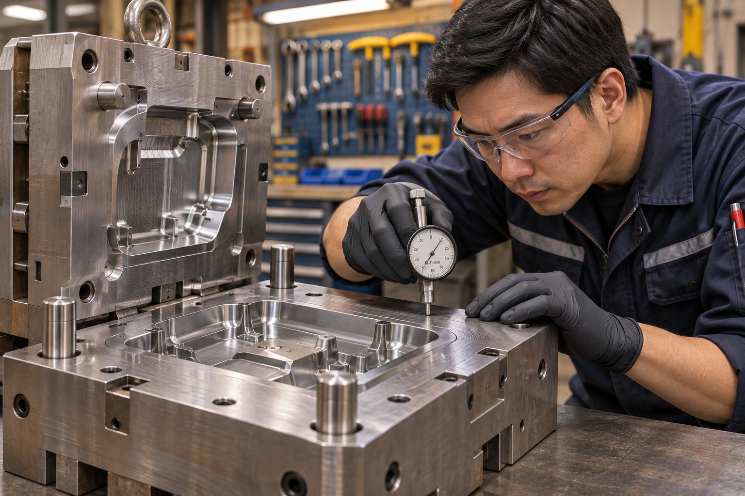
- Inspect the parting line at the flash location using spotting ink (blue dye in the U.S., red in China). Apply ink to one mold half, close the tool, and examine the transfer pattern. Gaps or light spots reveal areas where the steel is not sealing.
- Measure shut-off surfaces on slides, lifters, and action components. Check for wear, looseness in locking mechanisms, and heel block condition.
- Measure vent depths with a depth micrometer or optical comparator. Compare readings against the resin manufacturer's flash-free vent depth specification. Vents that have worn deeper than the limit need to be welded and recut.
- Inspect ejector pin bores at the flash location. Replace worn pins and ream or rebush oversized bores.
Branch C — Material-Side Diagnosis (indicated when pressure and mold checks come back clean, or when flash correlates with a resin lot change):
- Verify the incoming resin lot number against the previous lot that ran flash-free. Check whether the supplier changed the MFI grade, filler percentage, or base resin formulation.
- Test moisture content with a moisture analyzer. For hygroscopic resins like nylon, even a small rise above the recommended drying threshold can lower viscosity enough to trigger flash at previously acceptable pressure settings.
- Confirm actual melt temperature at the nozzle using a pyrometer or melt probe — not just the barrel zone setpoints. A malfunctioning thermocouple or heater band can push melt temperature above the target without any visible alarm.
The fastest path to solving flash is not adjusting everything at once — it is asking the right sequence of questions so you change only what actually needs changing.
This branching approach prevents the most common troubleshooting mistake on the production floor: reflexively lowering pack pressure or melt temperature every time flash appears, regardless of the actual cause. Those adjustments may suppress the symptom temporarily, but if the real culprit is a worn parting surface or a moisture-laden resin lot, the flash will return — and the process compromises you introduced will degrade part quality in ways that are harder to see. Disciplined diagnosis protects both the parts and the process window.
Of course, even a perfectly executed diagnostic fix only solves today's problem. Flash that traces to wear, erosion, or component degradation is telling you something about the long-term health of your mold and machine. The question shifts from "how do I fix this flash?" to "how do I keep it from coming back?" — and that requires a proactive maintenance strategy built around scheduled inspections, measurable wear thresholds, and deflashing prevention rather than deflashing reaction.
Proactive Mold and Machine Maintenance to Prevent Flash Plastic Defects
Diagnosing flash and correcting it in the moment is essential — but what separates shops that constantly firefight from those that rarely see the defect at all? A structured, frequency-based maintenance program that catches wear before it reaches the point where flash appears on parts. Too many facilities treat mold and machine maintenance as a reactive event: something breaks or a customer complains, and then someone inspects the tool. By that point, parting surfaces have already degraded, vent channels have eroded past their flash-free depth, and the shop has been shipping marginal parts for weeks. Flipping from reaction to prevention starts with knowing exactly what to inspect, how often, and what thresholds trigger corrective action.
Mold-Side Maintenance Schedules and Parting Line Refurbishment
The mold is where flash physically forms, so mold-side maintenance carries the heaviest weight in any prevention strategy. Every sealing surface in the tool — parting lines, shut-offs, vent channels, ejector pin bores — is subject to progressive wear that slowly opens the gaps where flash plastic escapes. The rate of that wear depends heavily on the resin being processed: a mold running unfilled ABS might hold its parting-line seal for hundreds of thousands of shots, while the same tool running 30% glass-filled nylon could start flashing in a fraction of that cycle count.
A shot-count-based maintenance tier system is far more effective than a calendar-based schedule because it scales inspections to actual tool usage rather than arbitrary time intervals. A mold cycling 50,000 shots per month accumulates wear five times faster than one running 10,000 — yet a calendar-based plan treats them identically. Here is what each inspection tier should cover for flash prevention specifically:
- Every run (pre-production setup): Inspect parting line faces for flash residue, visible damage, or contamination from the previous job. Check that ejector pins retract flush with the cavity surface — a pin sitting even slightly proud will prevent full mold closure and introduce a gap. Verify slides and lifters return to their home position completely. Examine vent channels for resin buildup or blockage that could tempt a technician to deepen them past the flash-free limit.
- Every 50,000 shots: Assess parting line witness marks for crush and wear using spotting ink to verify full contact across the sealing surface. Clean all vent channels and confirm gas escape paths remain clear. Inspect ejector pins for scoring, mushrooming, or binding — any of which enlarges the pin-to-bore clearance that lets pressurized melt escape. Check guide pins and bushings for galling or uneven wear that could allow the mold halves to shift slightly during clamping.
- Every 150,000 shots: Measure vent depths with a depth micrometer or optical comparator and compare readings against the resin manufacturer's flash-free specification. Vents gradually deepen from erosion — especially under abrasive filled resins — and a channel that was within spec at mold build may have drifted well past the limit. Inspect slide wear plates and gibs for clearance, fit, and full stroke operation. Polish cavity and core surfaces to restore the original finish grade, and measure critical cavity dimensions against tolerance drawings to catch any steel deformation.
- Every 300,000 shots (major overhaul): Fully disassemble the mold and clean all components individually. Re-blue parting line surfaces to verify full contact and seal. Measure all core and cavity steel against original OEM dimensions and evaluate any components beyond tolerance for rebuild or replacement. Replace all wear items — ejector return springs, O-rings, slide gibs — regardless of visible condition. Perform a first-article inspection after reassembly before releasing the mold to production.
These intervals serve as baselines. If you are processing highly abrasive glass-filled resins, tighten them — perhaps inspecting vent depths at 75,000 shots instead of 150,000. If you are running unfilled commodity resins on a low-volume tool, you may safely extend intervals based on your defect history. The key is to have intervals tied to shot counts, not to wait until flash appears and then react.
Parting-line refurbishment deserves particular emphasis. When spotting ink reveals incomplete contact, the standard corrective action is to stone or polish the parting surface back to full seal. If wear has progressed beyond what polishing can restore — deep crush marks, erosion channels, or localized depressions — the parting surface may need welding and remachining. Deferring this work does not save money; it simply transfers the cost downstream as scrap, rework, and secondary deflashing operations that accumulate every shift the mold runs.
Machine-Side Checks Including Plasticizing Components
Mold maintenance alone cannot prevent flash if the machine itself is introducing variability. Several machine-side conditions directly influence whether the mold seals properly and whether the process delivers consistent pressure from shot to shot.
Clamp mechanism condition is the starting point. A toggle clamp system relies on linkage geometry to multiply force at full extension — but that multiplication depends on properly maintained pins, bushings, and lubrication. Worn toggle pins allow play in the linkage, reducing the effective clamping force and compromising repeatability. If the toggle cannot reach its designed lock-up position consistently, clamp tonnage varies from cycle to cycle, and some shots may not generate enough force to keep the mold fully sealed during packing.
Platen parallelism determines whether clamp force is distributed evenly across the mold face. If the platens are not parallel — due to tie-bar stretch imbalance, toggle wear, or platen deformation — one side of the mold receives more clamping pressure than the other. The result is flash on the light side and potentially excessive compression on the heavy side, accelerating wear on both the mold and machine. Verifying that tie-bar stretch is even across all bars during clamping is a straightforward check that catches this issue before it manifests as a quality problem.
Plasticizing component condition is the machine-side factor most often overlooked in flash discussions — yet it is a direct contributor to the intermittent, seemingly random flash that frustrates process engineers. The screw, barrel, and check ring assembly work together to deliver a precise, repeatable shot of molten material into the mold every cycle. When these components wear, the process loses its consistency in ways that no amount of parameter tuning can fully compensate for.
Here is the mechanism: as the check ring wears, it no longer closes predictably or seals consistently from cycle to cycle. During injection, some melt leaks backward past the worn ring instead of being driven forward into the mold. The machine repeats the same screw position and velocity, but the actual volume and pressure delivered to the cavity fluctuates. On cycles where the check ring happens to seat well, pack pressure transmits cleanly and parts come out flash-free. On cycles where the ring seats poorly, the screw must travel further to compensate, and the resulting pressure spike can push melt past parting surfaces — producing flash on some shots but not others.
Worn screw flights and enlarged barrel bores compound the problem. Material slips backward over eroded flight lands, reducing plasticizing efficiency and introducing shot-to-shot variation in melt temperature and homogeneity. The practical effect is a process that looks stable on paper — the setpoints have not changed — but delivers inconsistent results at the mold. Monitoring cushion consistency and shot-to-shot part weight provides valuable early clues that the plasticizing system is deteriorating, often well before the wear becomes visually obvious during teardown.
When inspection reveals that screw flights, barrel bore, or the check ring assembly have worn beyond acceptable tolerances, replacement with properly specified components is the corrective action — not further process adjustment. For molders evaluating screw and barrel replacement or upgrade, NANHAIYA's custom injection molding screw barrels offer an option tailored around machine specifications, resin characteristics, and shot requirements. Their technical review considers screw geometry, wear patterns, melting and mixing performance, and material-retention concerns to match the component to the specific application — an approach that helps restore the process consistency that worn plasticizing hardware quietly erodes.
A Preventive Maintenance Checklist by Frequency
Pulling all mold-side and machine-side tasks into a single frequency-based checklist gives maintenance teams a practical tool they can post at each press and follow without ambiguity. Here is a consolidated view:
- Every production run:
- Inspect parting line faces for flash residue, damage, or contamination
- Verify ejector pin flush return and slide/lifter home position
- Check vent channels for resin buildup
- Confirm clamp tonnage setting matches the mold requirement sheet
- Verify water line connections are secure with no visible leaks
- Weekly (or every 10,000-25,000 shots for high-volume tools):
- Lubricate ejector pins, slides, and lifters per OEM specifications
- Monitor cushion consistency and shot-to-shot part weight for plasticizing system health
- Inspect nozzle seat and sprue bushing for wear or drool
- Check hydraulic system for leaks, oil level, and pressure stability
- Quarterly (or every 50,000-150,000 shots):
- Assess parting line with spotting ink for full contact verification
- Measure vent depths and compare against resin flash-free specifications
- Inspect ejector pin bores for scoring, mushrooming, or enlargement
- Check tie-bar stretch across all bars for even clamping force distribution
- Verify platen parallelism against machine OEM specification
- Compare cooling channel flow rates to baseline measurements
- Annually (or every 300,000+ shots):
- Full mold disassembly, cleaning, measurement, and re-bluing of parting surfaces
- Inspect screw flights, barrel bore, and check ring for wear — replace if beyond tolerance
- Evaluate toggle mechanism condition including pin and bushing wear
- Replace all mold wear items regardless of visual condition
- Recalibrate clamp force measurement and verify against nameplate tonnage
- Perform first-article inspection after any mold reassembly or machine component replacement
The discipline of following this checklist consistently — not just when quality complaints surface — is what separates shops that prevent flash from those that perpetually chase it. Each inspection point targets a specific wear mode that, left unchecked, would eventually allow melt to escape the cavity. The cost of scheduled inspections is a fraction of the scrap, rework, and customer dissatisfaction that unmanaged wear produces over time.
Prevention, however, is not always perfect. Even with rigorous maintenance, some parts — due to geometry, material, or tolerance requirements — will occasionally carry flash that must be removed before shipment. The question then becomes: which removal method best fits the part, the resin, and the production economics? The answer varies dramatically depending on whether you are trimming a handful of large automotive panels by hand or deflashing thousands of tiny medical components in a cryogenic tumbler.
Deflashing Methods Compared: From Manual Trimming to Laser Removal
Sometimes flash survives every prevention effort. The mold is well-maintained, the process is dialed in, and the material is within spec — yet the part geometry, tolerance stack, or production economics still leave a thin fin of flashing plastic on the finished component. When that happens, the conversation shifts from "how do I prevent it" to "how do I remove it efficiently without damaging the part or destroying my margins?" The answer depends entirely on the part itself: its size, geometry, resin, required surface finish, and how many pieces you need to process per hour.
Six deflashing methods dominate production floors today, each occupying a distinct niche. Choosing the wrong one costs you time, money, and potentially part quality. Choosing the right one turns an unavoidable secondary operation into a controlled, predictable step in your workflow.
Manual and Mechanical Deflashing Approaches
Manual trimming — using knives, scissors, scalpels, or custom fixtures — is where most shops start, and where many stay far longer than they should. The appeal is obvious: zero capital investment, minimal training, and the ability to start immediately. A skilled operator can trim flash from a complex part with surgical precision, reaching areas that machines sometimes cannot.
The problems, however, scale with volume. As Products Finishing notes, manual deflashing is labor-intensive and time-consuming, particularly on parts with complex geometries or intricate features. Workers trim at different skill levels, and consistent results are not always achievable. One operator removes flash cleanly; the next gouges the parting line or leaves a stub that interferes with assembly. There is also a real safety cost — repetitive use of blades and trimmers leads to hand injuries and ergonomic strain, driving workers' compensation claims and increasing turnover in an already tight labor market.
When does manual trimming still make sense? For low-volume production runs, prototype parts, or oversized components that will not fit into any automated deflashing system, hand trimming remains practical. It also works as a touch-up step after machine-based deflashing removes the bulk of the material. But for any volume above a few hundred parts per run, the labor cost and quality inconsistency usually justify moving to a mechanized approach.
Mechanical tumbling and vibratory finishing take the next step up in automation. These batch processes place molded parts inside a drum or vibratory bowl along with application-specific media — typically polyester-based plastic pellets, sometimes combined with abrasives like silica, aluminum oxide, or zirconium. As the parts tumble or vibrate against the media, the flash in plastic is gradually abraded away.
Vibratory tumbling works well for small, geometrically robust parts that can withstand repeated contact without damage — think simple caps, plugs, or thick-walled housings. Throughput is reasonable since you process entire batches simultaneously. However, Nitrofreeze's technical comparison highlights several drawbacks: the abrasive media deposits dust on part surfaces that requires subsequent cleaning, wet tumbling creates chemical waste requiring disposal, and even with softer plastic media, delicate features like thin walls, snap fits, or textured surfaces risk damage. Parts with tight cosmetic requirements often come out of vibratory tumbling with dulled surface finishes — acceptable for hidden functional components, but unacceptable for consumer-facing parts.
Cryogenic, Laser, and Chemical Deflashing
Cryogenic deflashing represents the most significant advancement in flash removal technology for elastomers and small precision parts. The process works by cooling molded parts below the polymer's glass transition temperature using liquid nitrogen or gaseous nitrogen, causing the thin flash to become hard and brittle while the thicker part body retains its flexibility. Once the flash is embrittled, the parts are blasted with a cryogenic-grade polycarbonate media — available in diameters from 0.015 inch (0.381 mm) to 0.060 inch (1.525 mm) — that knocks the frozen flash off without affecting the underlying part geometry.
What makes this method particularly powerful is its precision. The computer-controlled process can reach inside cross-holes, blind holes, through-holes, and threaded features that manual trimming struggles with. It will not change critical tolerances or alter the part's surface finish. And because the polycarbonate media is non-abrasive and the cryogenic agents sublimate, the process leaves no residue behind — a critical advantage for medical devices, aerospace components, and food-contact parts where cleanliness standards are strict.
Real-world results illustrate the efficiency gains. An aerospace molder processing PEEK parts reduced deflashing costs by nearly 85% after switching from hand trimming to cryogenic deflashing while achieving more consistent quality. In another case involving liquid silicone rubber distal handles for medical applications, cryogenic deflashing saved six hours of labor for every 1,000 parts and reduced the scrap rate compared to manual methods. The process handles batches of tens to thousands of parts per cycle, and optimal parameters can be stored and recalled for future production runs, ensuring repeatable results across multiple lots.
The tradeoff is capital cost. Cryogenic deflashing equipment requires a meaningful initial investment, plus ongoing costs for liquid nitrogen or CO2 supply. For shops without the volume to justify in-house equipment, outsourcing to a cryogenic deflashing service provider — with standard turnaround times of roughly two days — offers a lower-commitment entry point. The economics work best for elastomers, small-to-medium thermoplastic parts, and any application where manual deflashing labor costs or quality inconsistency are already significant pain points.
Media blasting occupies a middle ground between mechanical tumbling and cryogenic processing. Instead of tumbling parts in a bulk media bed, targeted blasting directs abrasive or non-abrasive media at specific flash locations on individual parts or small batches. This selectivity makes it useful when flash occurs in predictable, localized areas — along a single parting-line edge or around a specific insert boundary — rather than distributed across the entire part surface. Glass bead, walnut shell, plastic, and dry ice media are all used depending on the resin and the aggressiveness required. The limitation is throughput: media blasting is more labor-intensive than fully automated batch processes, and achieving consistent results depends heavily on operator technique unless the system is fixtured and robotically controlled.
Laser deflashing brings the highest precision to flash removal, using focused laser energy to vaporize or ablate thin flash without contacting the part surface mechanically. You will find this method in medical device manufacturing and micro-molding applications where flash measured in microns must be removed from features measured in hundreds of microns — tolerances that no mechanical or cryogenic process can reliably achieve. Laser systems can be programmed to follow complex flash paths with sub-millimeter accuracy, and because there is no physical contact, there is zero risk of surface damage or dimensional change. The cost, however, reflects that precision: laser deflashing systems carry the highest capital expense of any method discussed here, and throughput is relatively low since each part requires individual processing. For high-value, low-volume medical or electronic components, the economics justify the investment. For commodity parts at high volume, they rarely do.
Chemical deflashing uses solvent-based solutions to dissolve or soften flash selectively. The part is immersed in or exposed to a chemical bath formulated to attack thin flash more aggressively than the thicker part body — exploiting the fact that flash has a much higher surface-area-to-volume ratio and absorbs the solvent faster. This method works for specific resin families where compatible solvents are available, and it can reach recessed or internal flash locations that mechanical methods cannot access. The downsides are significant: chemical handling and disposal introduce environmental, health, and safety compliance requirements; cycle times can be long depending on the resin and flash thickness; and not all polymers have suitable solvent options. Chemical deflashing is typically reserved for niche applications where no other method can reach the flash location or where the resin chemistry permits an efficient, well-characterized solvent interaction.
Choosing the Right Deflashing Method for Your Application
With six distinct methods available, the selection process comes down to matching your part's specific characteristics — size, geometry, resin, surface finish requirements, and production volume — against each method's strengths and limitations. The table below provides a side-by-side comparison to guide that decision:
| Method | Best For | Resin Suitability | Throughput | Relative Cost | Quality Consistency |
|---|---|---|---|---|---|
| Manual Trimming | Low-volume runs, prototypes, oversized parts, touch-up after machine deflashing | All resins | Low — one part at a time | Low capital, high labor | Variable — depends on operator skill |
| Vibratory Tumbling | Small, robust parts with simple geometries and non-cosmetic surfaces | Most rigid thermoplastics; risk of damage to soft or delicate materials | Medium — batch processing | Moderate capital, moderate operating (media, cleaning, waste disposal) | Moderate — surface finish may be dulled; abrasive dust requires post-cleaning |
| Cryogenic Deflashing | Elastomers, LSR, small-to-medium thermoplastic parts, intricate geometries | Excellent for rubbers, silicones, PEEK, nylon, and most thermoplastics | High — hundreds to thousands of parts per batch cycle | High capital (or outsource); moderate operating (nitrogen supply, media) | High — automated, computer-controlled, repeatable parameters stored per part |
| Media Blasting | Localized flash on specific part features; moderate-volume targeted removal | Most resins with appropriate media selection (glass bead, plastic, dry ice, walnut shell) | Low to Medium — depends on fixturing and automation level | Moderate capital; operating cost varies with media type | Moderate to High — consistent when fixtured; variable when manual |
| Laser Deflashing | Medical devices, micro-molded parts, high-precision electronic components | Most thermoplastics; best for resins that ablate cleanly without charring | Low — individual part processing | High capital; low operating (no consumable media) | Very High — programmable, non-contact, sub-millimeter accuracy |
| Chemical Deflashing | Internal or recessed flash locations; niche applications with compatible resin-solvent pairs | Limited to specific resin families with suitable solvent chemistry | Low to Medium — long soak times possible | Moderate capital; ongoing chemical and disposal costs; EHS compliance overhead | Moderate — dependent on process control of concentration, time, and temperature |
A few practical guidelines emerge from this comparison. If you are processing elastomers or silicone parts at any meaningful volume, cryogenic deflashing is almost always the right answer — the combination of batch throughput, gentle non-abrasive removal, and ability to reach complex internal features is unmatched. For rigid thermoplastic parts where flash is localized and cosmetic requirements are modest, media blasting with appropriate fixturing offers a good balance of cost and consistency. Laser deflashing earns its premium on medical, micro-molded, or electronic parts where no other method can achieve the required precision without risk of surface damage.
Vibratory tumbling fills a role for high-volume, low-complexity parts where a slightly dulled finish is acceptable — but be honest about whether the post-tumbling cleaning step and potential for surface marring actually save money compared to alternatives. And manual trimming, despite its limitations, remains the right choice for prototyping, very low volumes, or as a supplementary touch-up step alongside machine-based methods.
Deflashing is always a secondary operation that adds cost — the goal should be eliminating flash at the source whenever economically justified, and choosing the most efficient removal method when it cannot be eliminated.
That economic calculation — when prevention justifies its cost and when controlled deflashing is the smarter investment — is the final piece of the puzzle. The answer depends not just on the deflashing method itself, but on the full picture of flash-related costs: scrap rates, labor, equipment, cycle time penalties from over-conservative process settings, and the hidden cost of customer complaints. Quantifying those costs transforms the flash conversation from a technical exercise into a business decision with clear return-on-investment thresholds.

The Economics of Flash and a Prevention-First Decision Framework
Every flash defect carries a price tag — but most production teams only see the obvious portion. The trimming labor, the scrapped parts, the bag of flash trimmings tossed into the regrind bin. What they miss is the compounding cost structure underneath: the cycle time you sacrificed to keep flash at bay, the customer complaint that triggered a corrective action report, the mold repair you deferred because production could not afford the downtime. Until you quantify the full cost of flash in injection molding, you cannot make rational decisions about how much to invest in preventing it.
Quantifying the True Cost of Flash in Production
Flash-related costs fall into five categories, and most shops only track one or two of them. Here is the complete picture:
- Scrap and rework losses: When flash exceeds tolerance — typically beyond 0.05 mm for precision parts or 0.1 mm for standard components — the part either gets reworked or rejected outright. Engineered resins like PEEK, polycarbonate, or glass-filled nylon can cost $10 to $50 or more per pound, so material waste adds up fast. Flash-related defects contribute to what some industry sources estimate at up to 15% of all injection molding defects, making it one of the largest single contributors to scrap budgets.
- Deflashing labor: Manual trimming is the most common secondary operation on production floors, and the per-part time cost is deceptively high. In precision and medical applications, deflashing can consume 15 to 30 seconds per part. Imagine a four-cavity mold cycling every 30 seconds — that is 480 parts per hour coming off the press. If each one requires 20 seconds of hand trimming, you need roughly 2.7 full-time operators just to keep up with one machine. At fully burdened labor rates, those operators represent a significant ongoing expense that never appears on the mold's original cost justification. Calculate this for your own volumes and labor rates to see the real number — it is almost always larger than expected.
- Capital equipment for secondary operations: Shops that outgrow manual trimming invest in cryogenic deflashing systems, vibratory tumblers, or media blasting equipment. These are real capital expenditures — cryogenic systems in particular require meaningful upfront investment plus ongoing nitrogen or CO2 supply costs. Even outsourcing cryogenic deflashing to a service provider carries per-batch charges that accumulate across thousands of production lots.
- Cycle time penalties from over-conservative process settings: This is the cost almost nobody tracks, and it may be the largest of all. When a molder encounters flash, the reflexive response is to dial back the process: lower pack pressure, slow the injection speed, reduce melt temperature. Each of those adjustments suppresses flash — but also extends cycle time, reduces throughput, and can introduce competing defects like sink marks, short shots, or poor surface finish. A process running at 85% of its optimal speed to avoid flash is leaving 15% of its capacity on the table every hour, every shift, every week. Over the life of a production program, that lost throughput dwarfs the cost of the flash itself.
- Hidden costs of customer complaints and rejected shipments: A single rejected shipment triggers sorting, re-inspection, replacement production, expedited freight, and corrective action documentation. Beyond the direct expense, repeated quality issues erode customer confidence and can ultimately cost you the contract. These downstream consequences are difficult to quantify in advance but devastating when they arrive.
When you stack all five categories together, the true cost of flash typically runs three to five times higher than the visible scrap and rework line item on the production report. That multiplier is what makes the prevention-versus-deflashing decision so important — and why getting it wrong is so expensive.
When Prevention Pays and When Deflashing Makes Sense
Not every flash defect demands the same response. A cosmetic automotive interior panel with tight dimensional tolerances and a Class A surface finish needs zero visible flash — period. A hidden structural bracket buried inside an assembly, where a thin parting-line witness has no impact on form, fit, or function, may tolerate controlled flash that is removed with a quick tumbling pass. Treating both parts the same wastes resources on one and risks quality on the other.
The concept of acceptable flash is uncomfortable for some quality teams, but it is a legitimate engineering judgment. Industry standards acknowledge that minor witness marks at parting lines are normal in injection molding. The question is not whether flash exists — it is whether the flash that exists affects the part's intended performance. A casting flash ridge on a non-critical surface that falls within the customer's drawing tolerance is not a defect; it is a characteristic of the manufacturing process.
Invest in flash prevention when the cost of allowing flash — including deflashing labor, scrap, cycle time penalties, and customer risk — exceeds the cost of eliminating it through better tooling, tighter process control, or equipment upgrades.
Here is a practical framework for making that call:
| Application Type | Flash Tolerance | Recommended Strategy | Rationale |
|---|---|---|---|
| Cosmetic consumer parts, medical devices, sealing surfaces | Very tight (less than 0.05 mm) | Invest heavily in prevention: precision tooling, hardened steels, tight process control, frequent mold maintenance | Deflashing costs are high per part, quality inconsistency risks customer complaints, and any visible flash is a rejection |
| Functional parts with moderate tolerances (housings, brackets, connectors) | Moderate (0.05-0.10 mm) | Optimize process and maintain mold on schedule; budget for light mechanical deflashing if needed | Prevention pays for most of the defect; a cost-effective secondary operation handles the remainder |
| Hidden or non-critical parts with generous tolerances | Relaxed (greater than 0.10 mm acceptable) | Control flash through standard process optimization; accept and deflash as needed via tumbling or media blasting | Investing in premium tooling or ultra-tight process windows yields diminishing returns when the customer accepts minor flash |
The decision is ultimately part-specific, not plant-wide. A single mold shop may run some jobs where every dollar spent on flash prevention returns three dollars in savings, and other jobs where the most economical path is a simple vibratory tumbling step after molding. The discipline lies in calculating the actual numbers rather than applying a blanket philosophy.
The Flash Prevention Hierarchy — Design, Process, Maintain, Remove
Across every application type and tolerance level, one principle holds: the earlier in the production chain you address flash, the lower the total cost. Think of it as a hierarchy — each tier is less expensive and more effective than the one below it.
- Design it out in the mold. Proper projected-area-to-clamp-tonnage calculations, appropriate mold steel selection (H13 or S7 for high-wear areas), adequate shut-off geometry on slides and lifters, and precision-fit insert pockets eliminate the physical conditions that allow flash to form. This is the most cost-effective intervention because it prevents flash at the source, permanently. Mold design decisions are difficult and expensive to change after steel is cut.
- Optimize the process. Scientific molding principles — establishing switchover by cavity pressure response, setting pack pressure empirically through gate seal studies, and profiling injection velocity to minimize pressure spikes — keep the process within the mold's sealing capability. A well-optimized process runs at the fastest cycle time the mold and material allow without producing flash, maximizing throughput and minimizing the cycle time penalty that over-conservative settings impose.
- Maintain the equipment. Shot-count-based mold inspections, parting-line refurbishment, vent depth verification, and ejector pin bore checks catch wear before it reaches the point where flash appears on parts. On the machine side, clamp mechanism inspection, platen parallelism verification, and plasticizing component condition monitoring ensure the press delivers consistent force and consistent shots cycle after cycle. Where diagnostic investigation points to worn screw flights, an enlarged barrel bore, or an inconsistent check ring as a contributor to process variability and intermittent flash, replacing those components with properly specified hardware is often far more cost-effective than perpetual process band-aids. NANHAIYA's custom injection molding screw barrels offer one practical option at this tier — their technical review matches screw geometry to machine specifications, resin characteristics, and shot requirements, helping restore the plasticizing consistency that worn components quietly erode.
- Deflash as a last resort. When mold geometry, material behavior, or production economics make zero flash impractical, choose the deflashing method that matches the part's size, resin, surface requirements, and volume. Cryogenic deflashing for elastomers and precision parts, vibratory tumbling for robust commodity components, laser deflashing for micro-molded medical devices — each has a defined sweet spot. But never lose sight of the fact that every deflashing step is a cost you are paying because an upstream tier did not fully solve the problem.
This hierarchy is not theoretical — it is a practical roadmap for capital allocation. A shop that spends $5,000 on a parting-line refurbishment to eliminate flash at the source avoids $20,000 or more in annual deflashing labor. A team that invests in proper screw and barrel components matched to their resin eliminates the intermittent pressure spikes that cause unpredictable flash events, stabilizing a process that had been drifting for months. And a mold designer who specifies H13 steel on critical sealing surfaces avoids the progressive wear spiral that turns a clean-running tool into a flash-producing headache within a few hundred thousand shots.
Flash in injection molding is not a mystery — it is a predictable, diagnosable, and largely preventable defect with clearly defined causes and well-understood solutions. The shops that struggle with it are almost always chasing symptoms: tweaking pack pressure down, slowing injection speed, lowering melt temperature, and hoping the problem goes away. The shops that control it follow the hierarchy: design, optimize, maintain, and remove — in that order, every time. The difference between the two is not luck or talent. It is discipline, data, and a willingness to fix the cause instead of masking the symptom.
Frequently Asked Questions About Injection Molding Flash
1. What is the acceptable flash tolerance in injection molding?
Acceptable flash tolerance depends on the application. For precision and medical parts, flash should stay below 0.05 mm (0.002 in.). Standard industrial components typically allow up to 0.10 mm (0.004 in.). Hidden or non-critical parts with generous tolerances may accept flash above 0.10 mm if it does not affect form, fit, or function. Always refer to the customer drawing specification, as tolerance requirements vary by industry and end-use.
2. What is the most common cause of flash in injection molding?
Excessive pack and hold pressure is the single most common process-side cause of flash. During the packing phase, the cavity is already full, so any surplus pressure forces molten resin against every sealing surface in the mold — parting lines, vent channels, ejector pin bores, and slide shut-offs. However, flash can also stem from mold-side issues like worn parting surfaces, insufficient clamp tonnage relative to projected area, or material-side factors such as low-viscosity resins and moisture-driven viscosity shifts in hygroscopic polymers like nylon.
3. How do you remove flash from injection molded parts?
Six primary deflashing methods are available: manual trimming with knives or fixtures for low volumes, vibratory tumbling for small robust parts, cryogenic deflashing using liquid nitrogen to embrittle and blast off flash for elastomers and precision components, media blasting for localized flash removal, laser deflashing for micro-molded or medical parts requiring extreme precision, and chemical deflashing using solvents for niche resin-solvent compatible applications. The best choice depends on part size, geometry, resin type, surface finish requirements, and production volume.
4. Why does flash appear on some shots but not others in injection molding?
Intermittent flash typically traces to shot-to-shot process inconsistency rather than a fixed mold or parameter problem. A worn check ring that does not seat consistently is a frequent culprit — on cycles where it seals well, pressure transmits cleanly and parts are flash-free; on cycles where it seats poorly, pressure spikes push melt past parting surfaces. Other causes include moisture fluctuations in hygroscopic resins like nylon, lot-to-lot melt flow index variation, and toggle clamp mechanisms with worn pins that deliver inconsistent clamping force.
5. How can mold design prevent flash in injection molding?
Effective mold design prevents flash by ensuring the projected-area-to-clamp-tonnage ratio leaves adequate sealing force margin, specifying wear-resistant tool steels like H13 or S7 for critical sealing surfaces, maintaining vent depths within the resin manufacturer's flash-free threshold, designing balanced runner systems for multi-cavity molds, and providing adequate core support to prevent pressure-driven core shift. These design decisions are the most cost-effective flash prevention measures because they eliminate the physical conditions that allow melt to escape before the mold ever runs.
Written by
Nanhaiya Technical Team
Zhoushan Nanhaiya Plastic Machinery Co., Ltd.
The Nanhaiya technical team supports screw and barrel manufacturing projects through application review, technical communication, custom manufacturing coordination, and production and quality control.
Discuss Your Application
Related Articles
More insights on screw barrel technology and plastics processing.
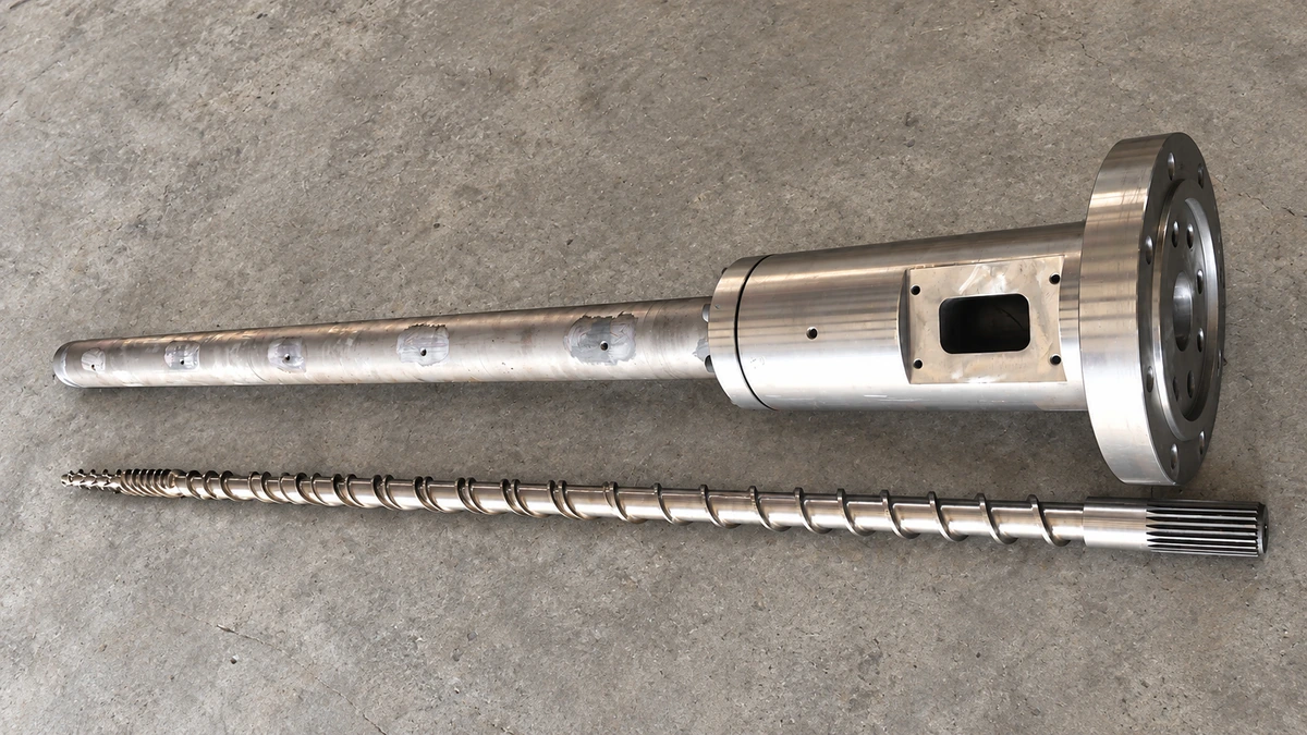
Why Your Single Screw Extruder Design Causes Extrusion Defects
Nov 13, 2026
Learn how single screw extruder design parameters—L/D ratio, compression ratio, channel depth, and mixing elements—affect melt quality, throughput, and defects.
Read Article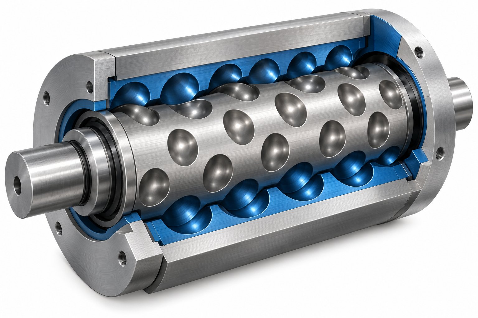
Cavity Transfer Mixer: The Blender Your Extruder Didn't Know It Needed
Nov 13, 2026
Learn how a cavity transfer mixer (CTM) upgrades single-screw extruder mixing. Covers working principles, key parameters, integration, applications, and comparisons.
Read Article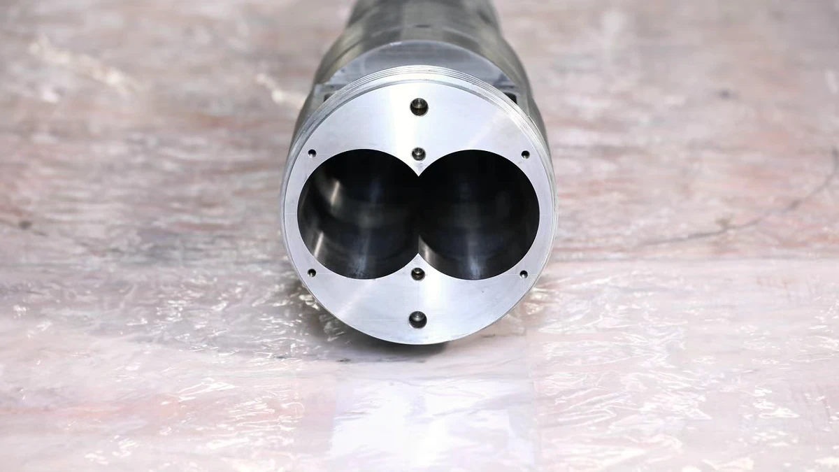
Extruder Barrel Alignment Decoded: Tolerances Most Plants Miss
Nov 13, 2026
Learn extruder barrel alignment tolerances, laser procedures, thermal offsets, and proactive schedules most plants miss — for single-screw and twin-screw lines.
Read ArticleLooking for something else?
Search by material, symptom or product and jump straight to the relevant page.
These are navigation suggestions based on keyword matching — not a quotation, not a delivery commitment, and not a substitute for engineering review. Final specification is confirmed by our engineers against your drawings and processed material.
Need help with screw barrel selection?
Share your machine model, processed material and application. Our team can help with pricing and technical support.