

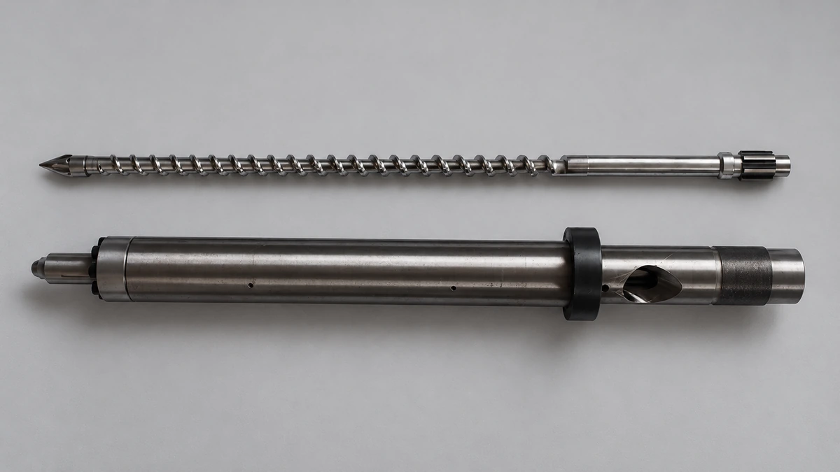
The Injection Molding Nozzle and Why It Matters
An injection molding nozzle is the heated passage at the front of the barrel that connects the plasticating unit to the mold's sprue bushing. It serves as the critical bridge between machine and mold, controlling the final condition of the molten polymer just before it enters the runner system and fills the cavity. Every shot your machine delivers passes through this single component, making it one of the most influential — yet frequently overlooked — elements in the entire molding process.
Why does this component deserve its own deep dive? Because it directly shapes part quality, cycle time, and process repeatability. As Bill Fierens of M. Holland puts it, "A chain is as strong as its weakest link, and an injection molding machine is as effective as its nozzle." A poorly chosen or worn-out nozzle tip quietly drives up scrap rates, and floor teams often chase the symptoms through mold adjustments or process tweaks without ever identifying the real source.
What an Injection Molding Nozzle Actually Does
Think of the injection nozzle as the final gatekeeper in your melt delivery path. It performs three core jobs simultaneously:
- Maintaining melt temperature — The nozzle sustains the thermal profile established by the barrel zones, ensuring the polymer arrives at the sprue bushing at the correct processing temperature.
- Providing a sealed flow path — It holds pressure during injection and packing, preventing melt leakage between the barrel and the mold. A plastic nozzle interface that leaks even slightly can cause carriage blow-back, flash at the sprue, or dangerous material buildup on the barrel.
- Enabling clean separation between shots — Whether through a freeze plug in an open design or a mechanical valve in a shut-off design, the nozzle must allow the mold to open cleanly and the next cycle to begin without drool or stringing.
None of these functions happen in isolation. The nozzle interacts with your screw design, check valve performance, barrel bore diameter, mold gating geometry, and runner type. A mismatch at any of these interfaces — say, a nozzle tip orifice that doesn't align with the sprue bushing — creates pressure imbalances, stagnant melt zones, or uncontrolled leakage that ripple through the entire process.
Why Nozzle Selection Impacts Every Molded Part
Imagine running a validated process that suddenly starts producing splay, short shots, or inconsistent cushion readings. The instinct is to adjust pack pressure or tweak barrel temperatures. But the root cause might be a worn nozzle seat, an undersized orifice generating excessive shear, or a temperature profile that lets material freeze off at the tip. Poor nozzle choice leads to a cascade of downstream defects: drool and stringing from an open design running low-viscosity nylon, freeze-off from inadequate heater wattage on an extended nozzle, material degradation from dead spots in a poorly tapered channel, and dimensional instability from cushion variation caused by melt leaking past a damaged seat.
The nozzle is the last controllable point in the melt delivery path before the polymer enters the mold. Getting it wrong undermines every upstream process optimization you have made.
This guide is built as a technical-yet-accessible reference for process engineers, mold setters, and maintenance teams who want to make smarter nozzle decisions. From selecting the right type and material of construction to sizing the orifice correctly and troubleshooting defects, each section targets a specific gap in the information typically available on the shop floor. The goal is straightforward: help you treat the nozzle as a strategic component rather than just another spare part — because the type of nozzle sitting at the end of your barrel determines far more than most molders realize.
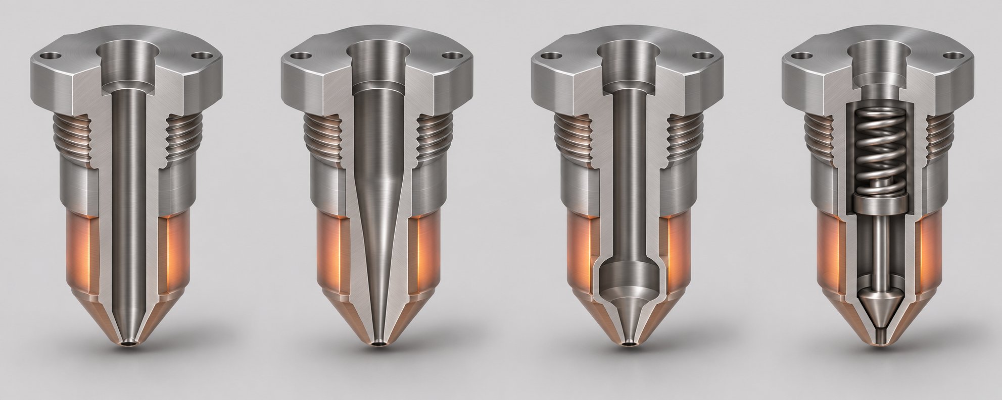
Every Injection Molding Nozzle Type Explained with Clear Use Cases
The type sitting at the end of your barrel shapes everything from drool behavior to pressure drop to how well your color disperses. Most references split injection molding nozzles into two buckets — open and shut-off — and stop there. That oversimplification leaves process engineers guessing when they encounter a resin, mold, or cycle-time challenge that falls between those two categories. In reality, there are at least nine distinct sub-types, each engineered to solve a specific set of problems. Choosing the wrong one is like selecting a general-purpose screw for a high-performance engineering resin: it might run, but it will never run well.
Open Nozzle Designs from General Purpose to Free-Flow
The open nozzle family shares one defining trait: no internal mechanism physically closes the melt channel between shots. Sealing relies on a freeze plug at the nozzle tip, pressure balance, or the resin's own viscosity. Within that family, you'll find meaningful differences.
General purpose (GP) nozzles are the default starting point on most machines. They feature a straight-through bore with a simple tapered tip — easy to heat, easy to clean, and inexpensive to replace. If you run relatively viscous commodity resins like PP or PE on cold-runner molds, a GP nozzle is often all you need. The trade-off? Minimal drool control and moderate dead-spot risk where color or degraded material can hang up.
Full-taper nozzles refine that basic design by tapering the entire internal channel from the barrel bore diameter down to the orifice. The smooth, continuously narrowing flow path virtually eliminates dead spots, making full-taper designs the preferred choice for heat-sensitive resins — think POM or certain grades of PC — where stagnant melt pockets cause degradation, black specks, or formaldehyde off-gassing.
Reverse-taper nozzles take a different approach to drool prevention. An undercut near the orifice creates a mechanical lock: the nozzle plastic solidifies into a small mushroom-shaped plug that physically cannot pull forward through the narrower exit. When the mold opens, the plug stays with the sprue and is pulled free. This makes reverse-taper designs particularly effective for low-viscosity resins like nylon (PA6, PA66) that drool aggressively from standard open tips.
Free-flow nozzles maximize throughput by offering the largest possible internal bore and the smoothest transitions. Pressure drop is minimal, which benefits large-shot-weight applications or resins that are shear-sensitive. The downside is that drool management is entirely dependent on process settings, so free-flow nozzles work best with higher-viscosity materials or molds that use a sprue break.
Extended (elongated) nozzles are not a separate flow-path philosophy but rather a length variation applied to any of the above designs. You'll reach for an extended nozzle when deep mold stacks, specific platen configurations, or stack-mold layouts require additional reach between the barrel face and the sprue bushing. Keep in mind that added length increases residence time, pressure drop, and the risk of freeze-off — all of which demand careful heater-band sizing and thermocouple placement.
Shut-Off and Valve-Gated Nozzle Designs
When drool, stringing, or cushion instability pushes scrap rates above target, a positive shut-off becomes necessary. These designs use an internal mechanism — a pin, ball, or blade — to physically close the melt channel between injection cycles.
Spring-loaded shut-off nozzles are the simplest automatic option. A heat-resistant spring holds a needle valve closed; melt pressure during injection compresses the spring and opens the flow path. Once pressure drops, the spring reseats the needle. As Plastics Technology notes, this design works automatically without operator intervention, external sensors, or hydraulic hookups — and it includes a built-in safety release if barrel pressure builds during an unattended idle period. Spring-loaded designs suit small to mid-size machines running general-duty applications.
Hydraulic and pneumatic valve-gated nozzles use an external cylinder to drive the shut-off pin or sleeve. The actuation timing is controlled by the machine's sequence logic, giving process engineers precise control over when the melt channel opens and closes. These designs are essential on vertical presses (where gravity causes severe drool), unscrewing molds that require nozzle retraction every cycle, and multi-shot or overmolding applications where the press frequently disengages from the mold. The trade-off is added complexity: external plumbing, control wiring, and more maintenance checkpoints.
For LSR (liquid silicone rubber) molding, the choice between open nozzle and valve gate carries unique considerations. SIMTEC Silicone Parts points out that high-cavitation LSR molds using valve gates tend to experience greater filling imbalance due to friction among moving parts, while open nozzle systems act as equalizers — allowing material to flow back into the cold runner during vulcanization when the LSR expands.
Specialty Nozzles for Mixing and Filtering
Beyond flow-path geometry and shut-off behavior, two specialty categories solve problems that standard designs simply cannot address.
Mixing nozzles incorporate internal elements that repeatedly divide, redirect, and recombine the melt stream. A well-designed triple-action mixing nozzle folds the melt onto itself through three alternating spiral rotations, delivering gentle yet thorough dispersion of colorants and additives without excessive shear. This makes mixing nozzles valuable for press-side color dosing, temperature homogeneity improvement, and additive distribution in cosmetic parts. The caution: increased residence time and complex internal geometry mean more purge shots during color changes and a higher risk of hang-up if cleaning is neglected.
Filtering nozzles — available as screen-pack or gap-filter (edge-filter) designs — catch solid contaminants, unmelted pellets, and foreign particles before they reach the mold gate or hot runner nozzle tips. Screen packs are simple and cheap but create significant pressure drop and clog quickly. Gap-filter designs turn the filtration 90 degrees, offering a much larger effective flow area and dramatically lower pressure loss. Some gap-filter nozzles even allow in-place purging of captured contaminants without disassembly, cutting cleaning downtime from hours to minutes. Avoid filter nozzles with shear-sensitive resins like PVC or POM, where the tight passages can trigger thermal degradation.
| Nozzle Type | Operating Principle | Best For (Resin Types) | Pressure Drop | Drool Prevention | Typical Applications |
|---|---|---|---|---|---|
| General Purpose (Open) | Straight-through bore, simple taper at tip | PP, PE, PS, ABS — higher-viscosity commodity resins | Low | Minimal — relies on freeze plug | Cold-runner molds, general-purpose production |
| Full Taper | Continuously tapered channel eliminates dead spots | POM, PC, heat-sensitive engineering resins | Low to moderate | Minimal | Parts requiring zero degradation or black specks |
| Reverse Taper | Undercut near orifice creates mechanical plug lock | PA6, PA66, low-viscosity nylons | Low | Excellent — mechanical plug retention | Horizontal presses running drool-prone resins |
| Free-Flow | Maximum bore diameter, smoothest transitions | Large-shot-weight or shear-sensitive resins | Very low | Poor — process-dependent only | High-throughput commodity molding, large parts |
| Extended (Elongated) | Lengthened version of any open or shut-off design | Any resin requiring extended reach to sprue | Higher (length-dependent) | Varies by base design | Stack molds, deep platen setups |
| Spring-Loaded Shut-Off | Spring-held needle opens under melt pressure | General-duty resins, mid-viscosity materials | Moderate | Very good — automatic closure | Multi-shot molds, nozzle-retract cycles |
| Hydraulic Valve-Gate | External hydraulic cylinder drives pin open/closed | Low-viscosity resins, engineering polymers | Moderate | Excellent — timed positive shut-off | Vertical presses, unscrewing molds, overmolding |
| Pneumatic Valve-Gate | External pneumatic cylinder drives pin open/closed | Low-viscosity resins, LSR, multi-component | Moderate | Excellent — timed positive shut-off | LSR molding, clean-room applications |
| Mixing | Internal spiral elements fold and recombine melt | Color-concentrate dosing, additive blending (avoid shear-sensitive PET without triple-action design) | Moderate to high | Minimal (open flow path) | Press-side color changes, cosmetic parts |
| Gap-Filter (Edge Filter) | Cylindrical filter with machined ribs captures particles | Regrind-heavy runs, contamination-sensitive parts | Low to moderate | Minimal (open flow path) | Medical, optical, and electronic components |
| Screen-Pack Filter | Perforated metal disk captures contaminants | Applications where contamination cost outweighs pressure-drop penalty | High (increases as filter clogs) | Minimal | Legacy filtering, low-throughput jobs |
This table gives you a quick-reference starting point, but the right nozzle type is only half the equation. The material that nozzle is made from — and whether it can survive the resin you're processing — determines how long your selection actually holds up on the production floor.
Nozzle Materials of Construction and When to Use Each
A perfectly selected nozzle type loses its value fast if the metallurgy cannot withstand the resin running through it. Corrosive off-gases pit the bore. Glass fibers erode the orifice. Insufficient thermal conductivity triggers freeze-off on thin-channel designs. Yet most injection molding nozzle specifications stop at dimensions and thread size, leaving process engineers and maintenance teams to discover material mismatches the hard way — through premature wear, contaminated parts, or unplanned downtime. Understanding which alloy belongs in which application is the difference between a nozzle that lasts thousands of hours and one that fails in weeks.
Standard Tool Steels and Stainless Grades
For the majority of commodity and mid-range engineering resins, tool steel is the workhorse material for plastic injection molding nozzle construction. The most common grades you'll encounter are H-13, D-2, and 420 stainless — each offering a distinct balance of hardness, toughness, and corrosion resistance.
H-13 hot-work tool steel is the default choice across the industry, and for good reason. With a working hardness typically in the range of 44–52 HRC, H-13 handles the thermal cycling of repeated contact with a cooled mold without cracking or softening. Its combination of hot hardness, impact toughness, and machinability makes it ideal for general-purpose molding of unfilled resins like PP, PE, PS, ABS, and standard PC. Under normal processing conditions with non-abrasive, non-corrosive polymers, an H-13 nozzle body can deliver years of reliable service before measurable wear affects performance.
D-2 tool steel steps up when abrasion resistance matters more than impact toughness. At 58–62 HRC, D-2 is significantly harder than H-13 and resists erosive wear from lightly filled compounds. However, its higher carbide content makes it more brittle, so it suits applications where the nozzle isn't subjected to heavy mechanical shock — think injection molding nozzle tips on machines running moderately filled resins at stable process conditions.
420 stainless steel fills the gap when molders process resins that release mildly corrosive byproducts but don't justify the cost of exotic alloys. Hardened to 48–52 HRC, 420 stainless provides decent wear resistance alongside meaningful corrosion protection. It's a practical upgrade for shops running certain flame-retardant ABS or PC blends, acetals under controlled conditions, or any application where occasional moisture exposure could rust a standard tool steel nozzle during downtime.
High-Performance Alloys for Aggressive Polymers
Standard steels reach their limits when the resin itself becomes the aggressor — either through chemical attack, extreme temperature requirements, or high abrasive filler loading. That's where specialty alloys earn their higher price tag.
Beryllium copper (BeCu) is not chosen for hardness or corrosion resistance. Its advantage is thermal conductivity — roughly five to seven times higher than H-13 steel. In thin-orifice injection molding nozzles prone to freeze-off, BeCu transfers heat far more efficiently to the nozzle tip, keeping the melt channel open even during extended mold-open times or when processing resins with narrow processing windows. You'll find BeCu specified for small-orifice nozzle tips, extended nozzle designs where heat loss along the length is a concern, and applications where cycle time is limited by nozzle freeze-off recovery. The trade-off is lower wear resistance compared to tool steel, so BeCu works best with unfilled, non-abrasive resins.
Inconel and nickel-based alloys address the most chemically hostile processing environments. When you run PVC, the thermal degradation of the polymer releases hydrogen chloride gas — an acid that aggressively attacks carbon steels and even 420 stainless over time. PVDF and fluoropolymers are even worse, generating traces of hydrofluoric acid that will pit standard injection molding nozzles within days. Inconel 625 and similar nickel-chromium-molybdenum alloys resist these corrosive off-gases, maintaining bore integrity and surface finish far longer than any steel grade. If your plant processes flame-retardant compounds containing halogenated additives, nickel alloy construction should be on the shortlist for every melt-contact component, including the nozzle body, tip, and internal flow path.
Tungsten carbide inserts and bimetallic liners solve the abrasion problem. Glass-filled nylon, mineral-filled PBT, and carbon-fiber-reinforced engineering resins act like liquid sandpaper flowing through the nozzle channel. Research into abrasive filament behavior has demonstrated that fiber-reinforced compounds preferentially erode the nozzle tip and orifice edge — and once that edge geometry degrades, part quality drops rapidly. In injection molding, the same principle applies at vastly higher pressures and flow rates. Tungsten carbide nozzle tip inserts, with hardness ratings exceeding 85 HRA, resist this erosive wear for extended production runs. Bimetallic nozzle bodies — a tool steel outer shell lined with a centrifugally cast wear-resistant alloy — extend protection along the entire internal bore, making them the right call for high-volume molding of heavily filled compounds where replacing an injection molding screw tip or nozzle every few weeks would be unacceptable.
Quick-Reference: Polymer Family to Nozzle Material
When you're standing on the shop floor deciding what material your next nozzle should be, start with the resin. Here's a practical mapping to speed up the decision:
- PE, PP, PS, ABS (unfilled) — H-13 tool steel. Standard workhorse; no special requirements.
- PC, PMMA, SAN (unfilled) — H-13 or 420 stainless. Stainless preferred if extended idle periods risk surface corrosion.
- Nylon PA6/PA66 (unfilled) — H-13 tool steel with proper nozzle type for drool control; material of construction is less critical than nozzle design.
- POM (acetal) — H-13 or 420 stainless with full-taper flow path to prevent formaldehyde buildup in dead spots.
- Glass-filled PA, PBT, PET — Tungsten carbide nozzle tip inserts or bimetallic-lined nozzle body. H-13 alone will erode rapidly.
- Carbon-fiber-reinforced resins (PA, PEEK, PPS) — Tungsten carbide inserts mandatory for injection molding nozzle tips; bimetallic bore lining recommended for high-volume runs.
- Mineral-filled compounds — D-2 or tungsten carbide inserts depending on filler loading and production volume.
- PVC (rigid and flexible) — Inconel or nickel alloy construction. Standard steels will pit and corrode from hydrogen chloride off-gassing.
- PVDF, ETFE, fluoropolymers — Inconel 625 or equivalent nickel alloy. Non-negotiable due to hydrofluoric acid exposure.
- Flame-retardant compounds (halogenated) — Nickel alloy or 420 stainless minimum; Inconel preferred for high-halogen formulations.
- PEEK, PEI, PPS (unfilled) — H-13 or 420 stainless with high-temperature-rated construction; upgrade to nickel alloy if processing temperatures exceed 400 °C or corrosive additives are present.
- TPE, TPU (unfilled) — H-13 tool steel. Focus nozzle selection on orifice size and dead-volume minimization rather than exotic metallurgy.
- LSR (liquid silicone rubber) — 420 stainless or nickel-plated steel to resist the platinum-cure catalyst environment.
Keep in mind that filler type and loading percentage shift the equation significantly. An unfilled nylon runs beautifully through an H-13 nozzle for years, but add 30% glass fiber and that same nozzle tip will show measurable erosion within weeks of continuous production. The smartest approach is to match the nozzle material to the most demanding resin in your production schedule — and that demands knowing exactly how each alloy performs when the orifice and bore geometry must stay precise shot after shot.
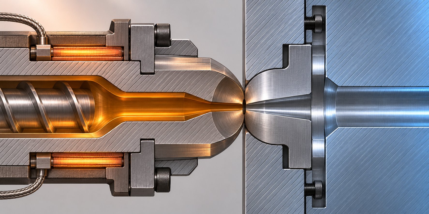
How to Size an Injection Molding Nozzle Correctly
Choosing the right nozzle type and metallurgy only gets you halfway. If the orifice is too small, you starve the mold of pressure and risk freeze-off. If it's too large, you lose drool control and introduce cold slugs. If the internal geometry creates dead spots or the nozzle length doesn't match your platen layout, every shot carries a penalty — whether you see it as splay, dimensional variation, or an unexplained jump in cycle time. A reliable injection nozzle sizing guide starts with one scientific molding principle: the nozzle should never be the flow-restriction bottleneck in the melt delivery path.
Orifice Diameter and Its Relationship to Shot Size
The injection molding nozzle orifice size is arguably the single most consequential dimension on the entire component. Too small, and you force the polymer through a restriction that generates excessive shear heating and eats into available injection pressure. Too large, and the melt drools freely between shots, creating cold slugs that wind up in your parts the next cycle.
Here's the core sizing rule: the nozzle orifice must always be smaller than the sprue bushing orifice. Why? If the nozzle bore is equal to or larger than the sprue opening, an undercut forms at the junction. Material solidifies into that undercut, and every mold-open stroke fights to shear the cold slug free — causing stringing, hang-ups, or chunks of degraded material that contaminate the next shot.
How much smaller? A common starting guideline is to keep the nozzle orifice roughly 1/32 in. (0.8 mm) smaller in diameter than the sprue bushing orifice. That difference provides a clean step-down into the sprue without creating a ledge that traps material. For example, if your sprue bushing has a 5/16-in. (7.9 mm) opening, a 9/32-in. (7.1 mm) nozzle orifice is a reasonable starting point.
Shot weight and fill rate push the minimum orifice size upward. Larger shots demand more volumetric flow per unit time, and forcing that flow through a pinhole orifice drives nozzle pressure drop in injection molding to levels that steal capacity from the cavity-filling phase. As M. Holland's pressure loss methodology recommends, the air-shot pressure through the nozzle alone should not exceed approximately 4,500 psi (plastic pressure). If your pressure loss study reveals the nozzle consuming more than that, the orifice is almost certainly undersized for the application.
Material viscosity matters here, too. A high-flow nylon at 50 g/10 min MFR needs far less driving pressure to move through a given orifice than a stiff polycarbonate at 6 g/10 min. But that same low-viscosity nylon is more likely to drool from an oversized orifice. Balancing these competing demands — sufficient flow area to avoid shear-driven defects while maintaining enough restriction for drool control — is the art behind proper orifice sizing.
As Kruse Training explains, a small nozzle orifice can freeze the polymer prematurely because the tip contacts the cooled mold and loses heat rapidly. When freeze-off occurs, the cold plug may be injected into the next cycle, creating surface defects and process instability. The takeaway: always verify that the selected orifice diameter can sustain an open melt channel throughout the entire injection and packing phase for the specific resin and cycle time you're running.
Channel Geometry and Nozzle Length Considerations
The orifice gets most of the attention, but the internal channel behind it shapes flow behavior just as significantly. Imagine the melt traveling from the barrel bore — typically 30 to 80 mm in diameter depending on machine size — down to an orifice that might be only 3 to 8 mm across. How that transition happens determines whether the polymer arrives at the sprue in good condition or degraded.
Smooth, gradual tapers are non-negotiable. Abrupt step-downs create dead spots — pockets where the melt stagnates, overheats, and eventually degrades into black specks or discolored streaks. A full-taper internal geometry, where the bore reduces continuously from entry to exit, is the safest approach for heat-sensitive resins. The taper angle should be gentle enough to keep wall shear rates within the resin's processing window while steep enough to avoid an excessively long nozzle body.
Nozzle length introduces its own set of trade-offs. An extended nozzle is sometimes unavoidable — deep mold stacks, non-standard platen configurations, or stack-mold layouts all require additional reach. But every extra inch of nozzle length brings three consequences:
- Increased residence time — Polymer spends more time in the heated channel, raising the risk of thermal degradation, especially for heat-sensitive materials like POM or PVC.
- Higher pressure drop — Frictional losses along a longer flow path reduce the pressure available to fill and pack the mold. For molders already running near the machine's pressure ceiling, this can tip the balance toward short shots or sink marks.
- Greater freeze-off risk — A longer nozzle body has more surface area in contact with cooled machine components and ambient air. Without adequate heater-band wattage and proper thermocouple placement, the tip temperature can drop below the resin's no-flow temperature before the pack phase completes.
When an extended design is necessary, compensate by upsizing the heater wattage, positioning the thermocouple closer to the tip, and verifying through a pressure loss study that the added length hasn't consumed your pressure margin. A general rule of thumb: for every additional 50 mm of nozzle length beyond the standard configuration, expect to add 10–15% more heater capacity to maintain a stable thermal profile at the tip.
Matching the Nozzle to the Sprue Bushing
Even a perfectly sized orifice and beautifully tapered channel can't save you if the nozzle tip doesn't seat properly against the sprue bushing. This interface — where machine meets mold — is deceptively simple in concept yet mismatched far more often than most shops realize. Veteran process consultant John Bozzelli estimates that nozzle tips and sprue bushings are mismatched roughly nine out of ten times, even when both are nominally the same radius specification.
The geometry at this junction follows a concave-to-convex contact principle. The nozzle tip has a spherical concave radius, and the sprue bushing has a convex (or matching spherical) radius. For a leak-free seal, the nozzle radius must always be smaller than the sprue bushing radius. This ensures contact occurs at the center of the interface — directly around the orifice — rather than at the outer edges.
The nozzle spherical radius must always be smaller than the sprue bushing radius to ensure a seal at the center of contact. A half-inch nozzle tip should never be paired with a half-inch sprue bushing of the same exact radius — a mismatch of even a few thousandths creates an outer-edge seal that leaks under injection pressure.
When proper nozzle sprue bushing alignment fails, the consequences cascade quickly. A gap at the center of the interface creates a venturi effect that sucks air into the melt stream, producing splay and silver streaks that mimic moisture-related defects. Leakage at the junction allows molten polymer to escape onto the barrel face, encrusting heater bands, thermocouples, and wiring — damage that Bozzelli documents as costing shops thousands of dollars in downtime, labor, and replacement parts. Excessive contact area at the outer edge, meanwhile, conducts too much heat from the nozzle into the cooled mold, accelerating freeze-off and generating cold slugs.
How do you verify proper mating? Two practical methods work well on the shop floor:
- Pressure-sensitive film — Place a piece on the sprue bushing face, bring the injection unit forward under normal contact force (typically 2 to 10 tons depending on machine size and expected melt pressures), then retract and inspect the imprint. You want a small, symmetrical, well-defined ring centered on the orifice. A broad, diffuse contact pattern signals excessive radius match or wear.
- Bluing agent — Brush a thin layer on one mating surface, engage the nozzle under tonnage, retract, and inspect the transfer pattern. Less precise than film, but readily available in most tool rooms.
Contact force itself deserves attention. Too little force allows melt to leak past the junction under injection pressure. Too much force can deform the nozzle tip or sprue bushing seat over time, accelerating wear and degrading the seal geometry that was correct at installation. Follow your machine manufacturer's recommended carriage-force settings, and inspect both the nozzle tip and sprue bushing seat during every scheduled mold change — not just when defects appear.
Getting the radius, orifice, and channel geometry right transforms the nozzle from a process liability into a stable, predictable link in the melt delivery chain. But geometry alone doesn't account for the resin-specific behaviors — drool tendency, degradation sensitivity, abrasive wear — that ultimately dictate whether your sizing decisions hold up over thousands of production hours.
Matching the Right Nozzle to Your Resin
Resin selection drives everything in injection molding — and nozzle selection by polymer type is the most practical way to apply the sizing, metallurgy, and design principles covered so far. On the shop floor, no process engineer starts by browsing a catalog of nozzle geometries. You start with the material data sheet, identify the resin's quirks — viscosity, thermal sensitivity, filler content, off-gassing behavior — and then work backward toward the nozzle configuration that handles those quirks without creating new problems. This section maps that workflow for every major polymer family you're likely to encounter.
Commodity and Engineering Resins
The good news? Commodity resins are forgiving. Polyethylene (PE) and polypropylene (PP) have relatively high melt viscosities, meaning drool is rarely an issue. A standard general-purpose open nozzle with an H-13 steel body is the default — and it works. Polystyrene (PS) and ABS fall into the same bucket, running cleanly through open designs without demanding exotic metallurgy or specialized flow paths. If you mold these resins on cold-runner molds at moderate cycle times, you can confidently select a GP nozzle and focus your optimization energy elsewhere.
Engineering resins introduce real complexity. Consider nylon — PA6 and PA66 are among the most commonly molded engineering polymers, yet they're also among the most nozzle-sensitive. Their low melt viscosity means they drool aggressively from open nozzle designs, stringing between the nozzle tip and sprue bushing every time the mold opens. The fix? A reverse-taper nozzle that mechanically locks a solidified plug at the orifice, or a spring-loaded shut-off that positively closes the melt channel between cycles. Selecting the right nozzle for nylon injection molding is often the single most impactful process decision you can make with these materials — before you ever touch a barrel temperature setpoint.
Polycarbonate (PC) and PBT are less drool-prone but more thermally demanding. Both resins benefit from full-taper nozzle designs that eliminate dead spots where the melt could stagnate and degrade. PBT, especially in flame-retardant grades, releases mildly corrosive byproducts that warrant a 420 stainless body over standard H-13.
POM (acetal) deserves special attention. When POM degrades — even slightly — it releases formaldehyde gas, which is both a health hazard and a quality killer. Dead spots inside poorly designed nozzle channels are the primary culprit. As Viplas notes regarding thermally sensitive polymers, specific geometry that avoids local overheating is essential. For POM, that means specifying a full-taper nozzle with no internal ledges, step-downs, or pockets where material can hang up and cook. Streamlined flow paths aren't optional here — they're a safety requirement.
High-Performance and Filled Polymers
Step into high-performance territory — PEEK, PEI (Ultem), PPS, and LCP — and the injection nozzle for PEEK processing or its peers must handle melt temperatures that routinely exceed 350 °C, sometimes pushing past 400 °C. Standard mica heater bands may not deliver sufficient wattage at these setpoints, so high-temperature ceramic or cast-in heaters become necessary. The nozzle body itself needs metallurgy that maintains structural integrity and corrosion resistance at sustained elevated temperatures; H-13 works for unfilled grades, but 420 stainless or nickel alloy construction provides a wider safety margin, particularly when processing PPS with its sulfur-containing byproducts.
Extended nozzle designs are common in this space because many high-performance applications involve thick-walled or geometrically complex parts with deeper mold stacks. The challenge is maintaining melt temperature uniformity across that extended length without allowing thermal degradation. Expect to specify higher-wattage heater bands and position thermocouples closer to the tip than you would on a standard-length nozzle running commodity resins.
Filled compounds represent a different — but equally demanding — challenge. Glass-filled nylon, mineral-filled PBT, and carbon-fiber-reinforced engineering resins behave like liquid abrasives. The fibers and particles preferentially erode the nozzle orifice and internal bore surfaces, particularly at points where the melt accelerates through restrictions. Choosing the best nozzle type for glass-filled resin starts with the tip material: tungsten carbide inserts are the standard protective measure, and bimetallic-lined nozzle bodies extend protection along the entire internal channel. Data from extrudr's analysis of fiber-reinforced materials confirms that both carbon and glass fibers are highly abrasive to standard metal surfaces — a principle that scales directly from additive manufacturing nozzles to injection molding nozzles operating at far higher pressures and throughput rates. Without hardened construction, you'll measure orifice erosion in weeks, not months.
LCP (liquid crystal polymer) adds a unique wrinkle: its extremely low viscosity at processing temperature demands shut-off nozzle designs similar to those used for nylon, while its high flow orientation sensitivity requires smooth internal transitions to avoid weld-line-like flow defects originating inside the nozzle channel itself.
Elastomers and Corrosive Resins
TPE and TPU materials are forgiving on metallurgy — H-13 handles them well — but demanding on geometry. These elastomers benefit from open nozzles with large orifices and minimal dead volume. Tight channels and complex internal features create hang-up zones where the soft, sticky melt clings and degrades. Keep the flow path simple, the bore generous, and the transitions smooth.
LSR (liquid silicone rubber) takes a different approach entirely. Because LSR is a thermoset that cures with heat, the nozzle must stay cool enough to prevent premature crosslinking while still delivering material at the correct viscosity. Open nozzle designs with large orifices are standard, and as noted in the earlier nozzle type comparison, open systems in high-cavitation LSR molds can actually improve filling balance by allowing material to equalize through the cold runner. A 420 stainless or nickel-plated body resists the platinum-cure catalyst environment typical of medical and food-grade LSR processing.
Corrosive and off-gassing resins — PVC, PVDF, ETFE, and other fluoropolymers — are where nozzle material selection becomes absolutely non-negotiable. PVC releases hydrogen chloride (HCl) during processing, an acid that aggressively attacks carbon steels, and even 420 stainless will pit over extended production runs. PVDF and fluoropolymers are worse still, generating traces of hydrofluoric acid that will destroy standard steels in days. Inconel 625 or equivalent nickel-chromium-molybdenum alloys are the only reliable solution for these materials. Beyond metallurgy, the nozzle design should minimize residence time — short, streamlined flow paths with low compression ratios prevent local overheating and reduce the volume of acid-generating degradation products.
| Polymer Family | Recommended Nozzle Type | Recommended Nozzle Material | Key Concern |
|---|---|---|---|
| PE, PP, PS, ABS (unfilled) | General purpose open | H-13 tool steel | Minimal — standard processing |
| Nylon PA6 / PA66 (unfilled) | Reverse taper or shut-off | H-13 tool steel | Drool and stringing |
| PC (unfilled) | Full taper open | H-13 or 420 stainless | Degradation in dead spots |
| PBT (flame-retardant grades) | Full taper open | 420 stainless steel | Mild corrosion from FR additives |
| POM (acetal) | Full taper open (streamlined) | H-13 or 420 stainless | Formaldehyde off-gassing from degradation |
| PEEK, PEI, PPS (unfilled) | Extended full taper, shut-off optional | H-13, 420 stainless, or nickel alloy | Extreme processing temperatures |
| LCP | Shut-off (spring or valve gate) | H-13 or 420 stainless | Low viscosity drool, flow orientation |
| Glass-filled PA, PBT, PET | General purpose or full taper | Tungsten carbide tip inserts, bimetallic bore | Rapid abrasive erosion |
| Carbon-fiber-reinforced resins | Full taper or free-flow | Tungsten carbide tip inserts, bimetallic bore | Severe abrasive wear |
| Mineral-filled compounds | General purpose or full taper | D-2 steel or tungsten carbide inserts | Moderate abrasive erosion |
| TPE / TPU | Open with large orifice | H-13 tool steel | Hang-up and degradation in dead spots |
| LSR (liquid silicone rubber) | Open with large orifice, minimal dead volume | 420 stainless or nickel-plated steel | Premature crosslinking, catalyst resistance |
| PVC (rigid and flexible) | Full taper, streamlined, short residence | Inconel or nickel alloy | HCl corrosion from thermal degradation |
| PVDF, ETFE, fluoropolymers | Full taper, streamlined, short residence | Inconel 625 or equivalent nickel alloy | Hydrofluoric acid attack |
This table gives you a resin-first decision path — but notice how many entries mention temperature-related concerns: freeze-off, degradation, premature curing, or the need for high-temperature heater bands. That's no coincidence. Nozzle type and material get you to the right hardware, but the thermal profile you run through that hardware ultimately determines whether the polymer arrives at the sprue in optimal condition or carrying the telltale signs of a temperature mismatch.
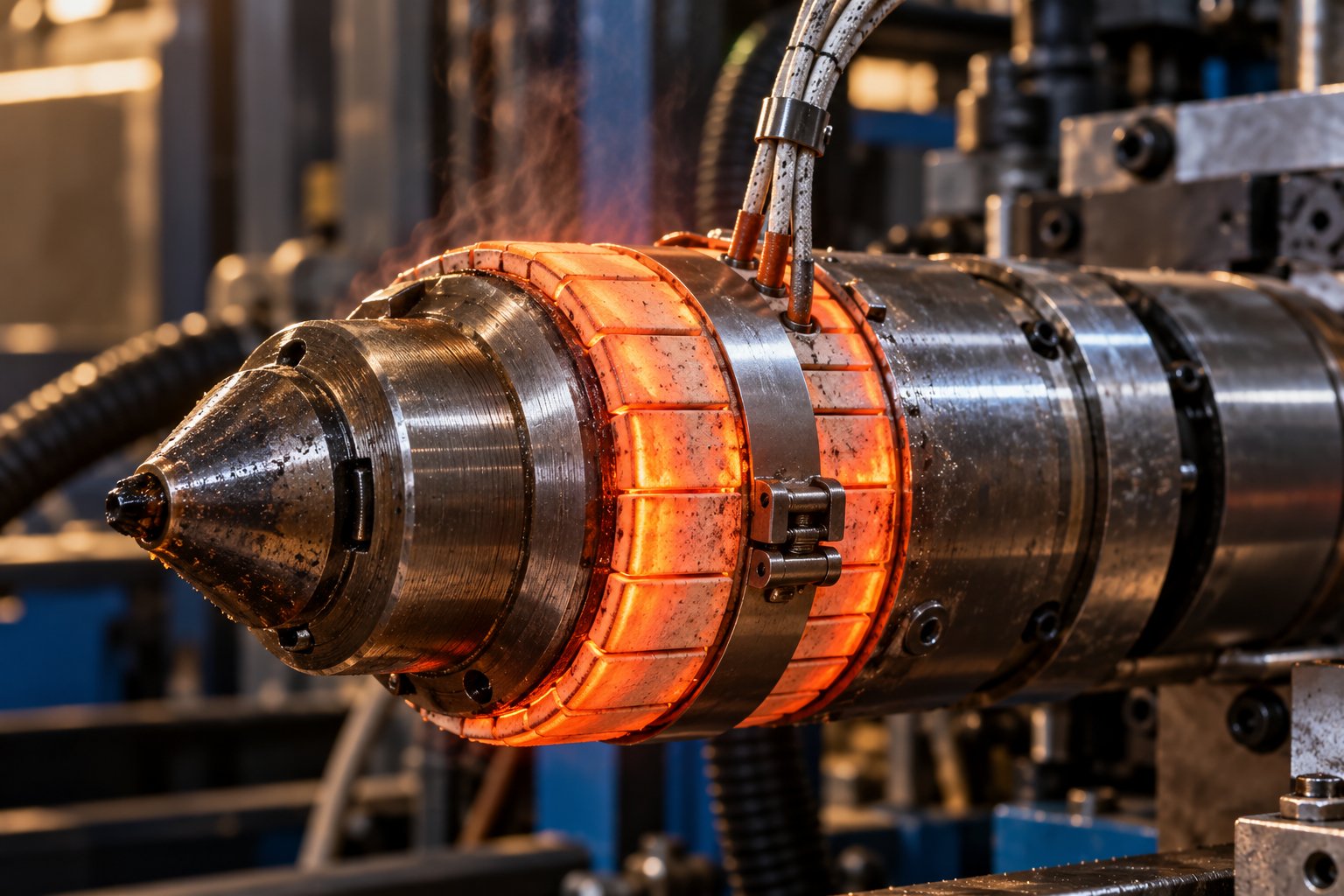
Nozzle Temperature Control and Hot Runner Interfaces
Temperature is the invisible variable that makes or breaks every decision covered so far. You can specify the ideal nozzle type, choose the perfect alloy, and nail the orifice diameter — and still produce scrap if the thermal profile running through that hardware is wrong. The injection molding nozzle temperature setting is arguably the most undertrained topic on the production floor, partly because it seems straightforward (just match it to the front barrel zone, right?) and partly because the consequences of getting it wrong — drool, freeze-off, degradation — mimic defects that are routinely blamed on other process variables.
What makes nozzle temperature control uniquely challenging? Unlike barrel zones, which are surrounded by insulation and maintain relatively stable thermal mass, the nozzle extends beyond the barrel's protective envelope. Every injection cycle, it presses against a cooled mold, losing heat rapidly through the sprue bushing contact area. Between shots, ambient air pulls additional energy from the exposed nozzle body. This constant thermal tug-of-war — heated from inside by the melt stream and heater bands, cooled from outside by the mold and environment — demands more precise control than any other zone on the machine.
Heater Bands and Thermocouple Placement on the Nozzle
Three heater band technologies dominate nozzle applications, each with distinct performance characteristics:
- Mica band heaters — The most common and least expensive option. A resistive element wound around a mica insulation core, clamped to the nozzle body with a simple band or screw. Mica bands heat up fast and are easy to replace, making them the default for commodity resin processing. Their limitation? Relatively low maximum operating temperatures (typically around 450 °C / 840 °F) and susceptibility to degradation from resin contamination. For standard PP, PE, ABS, or PS applications, mica bands are perfectly adequate.
- Ceramic band heaters — A step up in both durability and thermal performance. Ceramic insulation withstands higher temperatures, resists contamination better than mica, and delivers more uniform heat distribution across the nozzle surface. You'll want ceramic bands when processing engineering resins like PC, nylon, or PBT at elevated setpoints — or any application where mica bands are cycling excessively or burning out prematurely.
- Cast-in (integral) heaters — The premium option, where the heating element is cast directly into a metal sleeve that slips over or is machined into the nozzle body. Cast-in designs deliver the tightest thermal uniformity, the best band-to-body contact, and the highest wattage density. They're the right call for high-performance polymers like PEEK, PEI, and PPS, where processing temperatures exceed 350 °C and even small thermal gradients across the nozzle body can trigger degradation or freeze-off at the tip.
Wattage selection depends on nozzle size, the resin's processing temperature, and cycle time. A general guideline: you need enough installed wattage to recover the heat lost during every mold-contact period within the cooling phase of the cycle. Extended nozzles and fast-cycling molds demand proportionally higher wattage — as discussed in the sizing section, adding 10–15% heater capacity for every additional 50 mm of nozzle length beyond standard is a practical starting point. If your heater bands are running at or near 100% duty cycle during production, they're undersized for the thermal load.
Thermocouple placement is where many shops unknowingly set themselves up for nozzle freeze off prevention failures. The thermocouple tells the controller what the nozzle temperature is — but only at the point where it's installed. Place it on the nozzle body near the barrel connection, and you'll get a reading that's dominated by conducted heat from the barrel's front zone. The controller reads the setpoint, holds steady, and everyone assumes things are fine. Meanwhile, the nozzle tip — the point that actually matters, where the melt enters the sprue — may be 20–40 °F colder due to heat loss into the mold.
As injection molding expert John Bozzelli documents, nozzle thermocouple and heater band wiring placement is mishandled an estimated 98% of the time. Beyond placement location, the physical routing of wires creates its own hazards. Bozzelli describes how gravity pulls leaked molten plastic down onto dangling wires, progressively encrusting thermocouples and heater band connections until a wire breaks or shorts — triggering an unplanned shutdown that costs time, frustration, and replacement parts. His recommendation: route all wiring upward and to the non-operator side, protect cables in removable conduit, and use quick-disconnect plugs so that nozzle heater band replacement doesn't turn into a half-day maintenance event.
The practical rule for thermocouple placement? Position it as close to the nozzle tip as physically possible while still being protected from mechanical damage during mold changes. Some nozzle designs incorporate a thermocouple well machined directly into the tip area — if your nozzle offers this feature, use it. If not, clamp-on thermocouples at the tip end of the nozzle body provide a far more accurate reading than sensors placed midway along the body or near the barrel junction.
How the Machine Nozzle Interfaces with Hot Runner Molds
When your mold uses a hot runner system, the machine nozzle doesn't just seat against a passive sprue bushing — it connects to an actively heated inlet that feeds a temperature-controlled manifold and downstream hot runner nozzle tips. This hot runner nozzle interface introduces thermal management challenges that cold-runner molds never present.
The fundamental tension is straightforward: the machine nozzle must maintain its own melt temperature without overheating (or overcooling) the hot runner's inlet zone. Imagine your machine nozzle running at 230 °C while the hot runner manifold entrance is set to 215 °C. That 15-degree mismatch at the junction can cause localized overheating of the resin in the transition zone, leading to degradation streaks, gate blush, or thermal expansion issues in the manifold. Flip the scenario — a machine nozzle running too cold relative to the manifold — and you risk injecting a cold slug into the hot runner sprue that disrupts flow balance across all cavities.
Thermal separation is the design principle that manages this interaction. Many hot runner systems incorporate an insulating air gap or a titanium spacer between the machine nozzle contact point and the manifold body. This thermal break prevents the machine nozzle — which cycles between full melt temperature and partial cooling during mold contact — from destabilizing the hot runner's precisely controlled temperature zones. When you select a machine nozzle for a hot runner mold, verify that the tip geometry and length are compatible with the hot runner's sprue bushing design. A mismatch here creates the same problems seen in cold-runner applications — leakage, air entrapment, cold slugs — but with the added complication that leaked material can flow into the hot runner manifold space and cause far more expensive damage.
Nozzle tip geometry compatibility deserves extra scrutiny. Hot runner sprue bushings often use proprietary radius profiles or flat-face sealing surfaces that differ from standard cold-runner sprue bushings. Running a standard 3/4-in. radius nozzle tip against a hot runner that expects a 1/2-in. radius (or a flat seal) guarantees leakage under injection pressure. Always confirm the required tip geometry from the hot runner manufacturer's documentation before selecting or ordering a replacement machine nozzle.
One more distinction that matters for maintenance teams: the machine nozzle and the hot runner nozzle tips inside the mold are entirely separate components with different functions, materials, and replacement schedules. The machine nozzle is a barrel-side part you control. The hot runner nozzle tips — the components that convey plastic from the manifold directly into each cavity — are mold-side parts with their own heaters, thermocouples, and wear characteristics. Both require routine inspection and replacement, but confusing one for the other during troubleshooting leads to wasted effort. If you're seeing vestige issues, gate blush, or drool at the hot runner sprue, check the machine nozzle interface first. If those symptoms appear only at specific cavities, the hot runner nozzle tips are the more likely culprits.
Temperature control — at the machine nozzle and through the hot runner system — keeps the melt in its optimal processing window right up to the gate. But what happens when that window narrows or closes? The defects that follow — drool, freeze-off, black specks, dimensional drift — each trace back to specific nozzle-related root causes that experienced troubleshooters can systematically diagnose.
Troubleshooting Part Defects Caused by the Nozzle
You've dialed in barrel temperatures, validated your screw recovery, and confirmed proper mold cooling — yet the reject bin keeps filling up. The defect might look like a moisture problem, a check-ring failure, or a mold venting issue. But here's the catch: a surprising number of persistent, hard-to-diagnose quality failures originate at the nozzle. Because it sits at the junction of machine and mold, a worn, mismatched, or improperly heated nozzle creates symptoms that mimic problems elsewhere in the system. The key to efficient troubleshooting is learning to trace the symptom backward to its nozzle-related root cause — before you waste a full shift chasing ghosts.
Drool and Stringing Traced to the Nozzle
Drool — that frustrating blob or string of molten polymer hanging from the tip after the mold opens — is probably the most visible nozzle-related defect. It contaminates the sprue, creates cold slugs in the next shot, and leaves strings across the parting line that ruin cosmetic surfaces. Finding the right injection molding nozzle drool fix starts with a systematic diagnostic sequence rather than random parameter changes.
Step one: check the nozzle temperature profile. As Wanplas documents, the single most common cause of drooling is a nozzle zone running 10 °C to 30 °C above what the resin actually requires. The fix follows a "five-and-verify" approach: reduce the nozzle setpoint by 5 °C, run at least five stable cycles to clear the nozzle's thermal mass, then evaluate. Repeat until drooling stops or you reach the lower bound of the resin's processing window. Never raise temperature to stop drooling — higher temperature lowers viscosity and makes the problem worse, not better.
Step two: inspect the nozzle tip for wear or damage. A reverse-taper nozzle, for example, relies on a precise undercut geometry to form a mechanical plug that prevents drool. If that seat is worn, eroded from glass-filled compounds, or pitted by corrosive off-gases, the plug can't form properly and material weeps past it. Remove the nozzle tip and examine the seating surface under magnification. Any visible scoring, erosion at the orifice edge, or rounding of the undercut means replacement — no process adjustment will compensate for a physically damaged seal.
Step three: verify the nozzle type matches the resin's melt viscosity. Running an open general-purpose nozzle with nylon (PA6 or PA66) is a recipe for chronic drool. Low-viscosity resins need a reverse-taper or shut-off design — and if neither is installed, no amount of temperature reduction or decompression tuning will fully solve the problem. This is a hardware mismatch, not a process parameter issue.
Experienced molders also use an auditory diagnostic cue during suck-back. Listen carefully when the screw retracts after pack hold. A clean, quiet retraction indicates the melt is pulling away from the nozzle tip cleanly. A gurgling or slurping sound suggests air is being drawn into the melt — a sign of excessive decompression, a worn nozzle seat, or poor nozzle-to-sprue-bushing contact. Conversely, no audible change during suck-back on a machine that should be decompressing may indicate the decompression function is disabled or the distance is set too low to relieve front-end pressure.
If temperature reduction, tip inspection, and nozzle type verification don't resolve the issue, move downstream in the diagnostic chain: check that decompression (suck-back) is enabled and properly timed, reduce recovery back pressure to the minimum that maintains melt homogeneity, and verify nozzle-to-sprue contact pressure and timing. The structured correction sequence — temperature first, then mechanical inspection, then process parameters, then hardware changes — prevents the costly mistake of replacing parts that aren't actually failed.
Freeze-Off and Degradation at the Nozzle
Freeze-off is drool's opposite: instead of material leaking out, the melt solidifies inside the nozzle channel and blocks flow. The machine tries to inject, pressure spikes, and you get short shots, hesitation marks, or a cold slug that blasts into the cavity and shows up as a surface blemish near the gate. Nozzle freeze off troubleshooting follows its own diagnostic logic.
Start with heater band performance. Is the nozzle heater delivering adequate wattage? Mica bands degrade over time — especially when contaminated by leaked resin — and a band running at 60% of its rated output won't maintain setpoint during the heat-loss spike that occurs every time the nozzle contacts the cooled mold. Measure actual wattage draw with a clamp meter while the machine is cycling, not just during idle warm-up. A heater that reads correct resistance on a bench test may still underperform under production thermal loads.
Next, evaluate thermocouple placement. As discussed in the temperature control section, a thermocouple positioned too far from the nozzle tip reads barrel-conducted heat rather than actual tip temperature. The controller displays setpoint — 230 °C, everything looks fine — while the tip itself is sitting at 190 °C and forming a freeze plug every cycle. Moving the thermocouple closer to the tip, or switching to a nozzle design with an integrated thermocouple well at the tip, often resolves chronic freeze-off that has resisted every other adjustment.
Excessive nozzle contact time with the cooled mold is a less obvious culprit. On machines that maintain nozzle contact throughout the entire cycle (no sprue break), the nozzle tip bleeds heat into the mold continuously. If the cycle includes a long cooling phase — say, 30 seconds or more for thick-walled parts — the tip can cool below the resin's no-flow temperature before the next injection stroke begins. Solutions include programming a sprue break (nozzle retract) after pack hold to reduce contact time, increasing heater wattage, or switching to a beryllium copper nozzle tip that transfers heat more efficiently from the heater band to the melt channel.
Degradation at the nozzle often rides alongside freeze-off in a frustrating cycle. When a freeze plug forms, the melt behind it stagnates. That stagnant material sits at processing temperature with nowhere to go, slowly degrading. When the freeze plug finally breaks free — either from accumulated injection pressure or a temperature correction — it carries degraded polymer into the mold. The result? Black specks from nozzle degradation that appear intermittently, often as dark flecks or brownish-black streaks concentrated near the gate or sprue. CK Mold's diagnostic framework confirms that these degradation specks typically appear as streaky, smeared marks that are fused with the base material — distinct from the sharp-edged, clearly defined particles that characterize foreign contamination.
Dead spots in the nozzle's internal geometry are the other major degradation source. Any ledge, step-down, or poorly blended transition where the channel diameter changes abruptly creates a pocket where polymer hangs up, overcooks, and eventually breaks free as carbonized particles. If black specks persist after verifying barrel temperatures, screw condition, and material drying, pull the nozzle and examine its internal bore under good lighting. Dark discoloration, carbon buildup in corners, or rough surface texture at transitions point directly to geometry-related degradation. The fix is often a full-taper nozzle design with smooth, continuous internal transitions — exactly the type recommended for heat-sensitive resins like POM and PC.
Cushion Variation Linked to Nozzle Wear
Cushion instability — the shot-to-shot variation in the material remaining in front of the screw after injection — is one of the most confounding symptoms a process engineer faces. The immediate suspect is always the check ring (non-return valve), and rightfully so: a worn check ring leaks melt backward during injection, producing inconsistent cushion readings. But here's what many troubleshooters miss: a worn or eroded nozzle seat creates the same symptom through a completely different mechanism.
When the nozzle tip's sealing surface degrades — through erosion from abrasive fillers, corrosion from off-gassing resins, or simple mechanical wear from thousands of nozzle-touch cycles — it no longer forms a tight seal against the sprue bushing. During hold pressure, melt leaks forward past the degraded interface into the sprue area rather than packing the cavity. The screw position drifts forward as material escapes, and the cushion reading drops unpredictably. Injection molding cushion variation nozzle problems mimic check-ring failure so closely that shops routinely rebuild or replace the check ring — only to see the same variation return immediately because the actual leak is at the nozzle-to-sprue junction.
How do you differentiate the two? A practical field test works well. First, perform a standard check-ring leak test: build cushion, hold pressure, and monitor screw drift. If the screw creeps forward, you have a leak somewhere in the front end. Now, retract the carriage so the nozzle separates from the sprue bushing, and repeat the test by injecting into air (an air shot). If cushion holds steady during the air shot but drifts when seated against the mold, the leak is at the nozzle-to-sprue interface, not the check ring. If cushion drifts during the air shot as well, the check ring is the more likely culprit — though both can be worn simultaneously on machines with high production hours.
Inspect the nozzle tip's spherical seating surface for visible wear marks, erosion grooves, or flattening. Molders Services emphasizes that sealing-surface wear is the primary durability failure across front-end injection components — whether on the check ring, screw tip retainer, or nozzle seat. The same abrasive and corrosive forces that erode a check ring's OD also attack the nozzle tip where it meets the sprue bushing under tons of contact force, cycle after cycle.
Other nozzle-related defects worth tracing include splay and silver streaks (trapped air drawn in through a worn nozzle seat or excessive decompression, or moisture released from degraded material in dead spots), burn marks and discoloration (stagnant melt in poorly designed nozzle channels or excessive shear through an undersized orifice), and gate blush (a cold slug from the nozzle tip that enters the cavity first, creating a dull or discolored area at the gate). Each of these traces back to one or more of the nozzle variables covered throughout this article: temperature profile, orifice sizing, internal geometry, material of construction, and mechanical condition of the sealing surfaces.
Systematic Nozzle Inspection Checklist
Rather than waiting for defects to force a reactive teardown, build nozzle inspection into your scheduled preventive maintenance. The following checklist gives maintenance teams a repeatable sequence to follow during planned downtime:
- Visually inspect the nozzle tip exterior — Look for resin buildup, discoloration, cracking, or deformation at the contact face. Any material encrusting the heater band connections or thermocouple wiring signals a prior leak event.
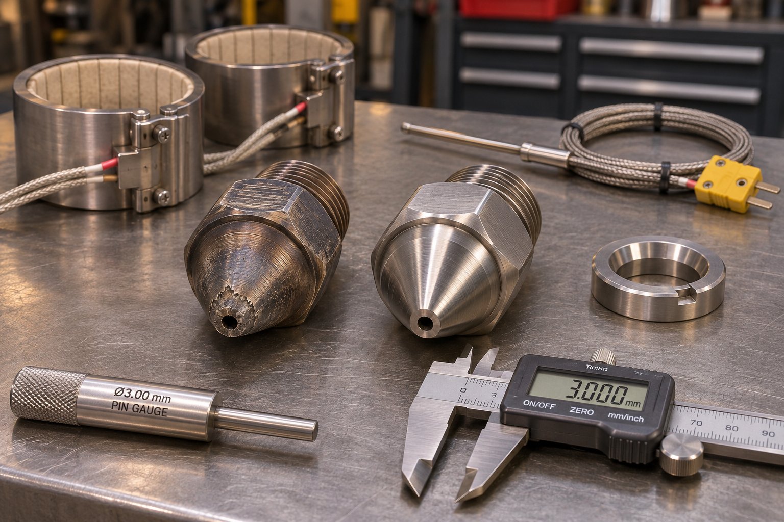
- Remove the nozzle tip and examine the orifice — Measure the orifice diameter with a pin gauge and compare to the original specification. Erosion beyond 0.1 mm on the orifice diameter warrants replacement, especially on applications running filled resins.
- Inspect the internal bore and channel transitions — Use a flashlight and magnification to check for carbon buildup, dark residue in corners, rough surface texture, or pitting from corrosive resins. Any visible dead-spot contamination indicates inadequate purging or a geometry that promotes hang-up.
- Check the spherical seating surface — Look for wear rings, flattening, grooves, or erosion on the concave radius that contacts the sprue bushing. Use a radius gauge to verify the profile hasn't deformed beyond specification.
- Measure heater band resistance — Compare to the manufacturer's rated value. A resistance reading more than 10% above nominal suggests element degradation. Bands with visible resin contamination, cracked insulation, or burned leads should be replaced immediately.
- Verify thermocouple condition and placement — Confirm the thermocouple is positioned as close to the nozzle tip as possible and that wiring is routed upward, protected from resin drips, and secured with quick-disconnect plugs for efficient replacement.
- Inspect the sprue bushing mating surface — The bushing wears too. Check for matching wear marks, deformation, or carbon deposits that indicate prior leakage. A worn bushing can undermine a brand-new nozzle tip.
- Test nozzle contact force and alignment — Engage the carriage and verify the nozzle seats concentrically against the sprue bushing with the manufacturer's recommended contact force. Misalignment causes uneven wear and eccentric leakage paths.
- Document findings and compare to previous inspections — Record orifice measurements, heater resistance, wear observations, and any parts replaced. Trending this data over time reveals wear rates that allow you to predict replacements before defects appear on the production floor.
This checklist transforms nozzle maintenance from a reactive scramble into a predictable, data-driven routine. But even the best inspection program depends on having the right replacement parts available when wear is identified — and knowing exactly what to order when a nozzle, tip, or associated component reaches end of life.
Maintaining and Replacing Injection Molding Nozzles
Catching wear during an inspection is only half the battle. The other half — and the part that separates shops with minimal downtime from those scrambling through emergency shutdowns — is having a reliable replacement workflow in place before a worn nozzle forces your hand. An injection molding nozzle replacement that goes smoothly depends on two things: knowing when to pull the trigger and knowing exactly what to order so the new component drops in without compatibility surprises.
When to Inspect and Replace a Nozzle or Nozzle Tip
A rigid calendar-based nozzle maintenance schedule injection molding teams apply universally — say, "replace every 5,000 hours" — sounds tidy but rarely reflects reality. A nozzle running unfilled polypropylene on a 20-second cycle degrades at a completely different rate than one processing 30% glass-filled nylon on a 45-second cycle. The smarter approach ties inspection triggers to observable production signals rather than arbitrary time intervals.
Watch for these red flags:
- Rising reject rates with no obvious process change — If scrap creeps upward while barrel temperatures, material lots, and mold condition remain stable, the nozzle or its tip is a prime suspect. Orifice erosion gradually shifts shear heating and pressure drop, degrading fill balance and part weight consistency shot by shot.
- Cushion variation that persists after check-ring verification — As covered in the troubleshooting section, a worn nozzle seat mimics check-ring failure. If you've already confirmed the non-return valve is sound, inspect the nozzle's spherical seating surface next.
- Visible drool or leakage at the nozzle-sprue interface — Any material escaping between the nozzle tip and sprue bushing during production is an immediate signal. Even minor seepage accelerates further wear, encrusts heater bands and thermocouple wiring, and can create dangerous conditions if it contacts hydraulic lines or electrical connections.
- Heater band cycling anomalies or thermocouple drift — A heater that cannot hold setpoint or a thermocouple reading that fluctuates erratically often indicates resin contamination on the nozzle body from a previous leak event. Once contamination compromises the heater or sensor, both the nozzle and its electrical components may need replacement together.
For shops running abrasive filled compounds, a practical baseline is to inspect the nozzle tip orifice with a pin gauge every scheduled mold change — not just when defects appear. Comparing measured orifice diameter to the original specification reveals erosion trends long before they manifest as part quality failures. On corrosive resins like PVC or fluoropolymers, add a visual inspection of the bore's interior surface for pitting and discoloration at the same interval. These nozzle tip wear indicators give your maintenance team lead time to source replacements proactively rather than reactively.
For general-purpose applications running unfilled commodity resins, a quarterly deep inspection — removing the nozzle, measuring the orifice, checking internal bore condition, and verifying heater and thermocouple health — provides a reasonable starting point. Adjust frequency upward based on wear history, and always log findings so you can establish machine-specific and resin-specific replacement intervals grounded in actual data.
Information to Gather Before Sourcing Replacement Parts
Here's where many maintenance teams lose time and money: ordering a replacement nozzle based on incomplete information. A part number alone is often insufficient — especially on older machines where OEM documentation is missing, the original nozzle has been replaced with an aftermarket version at some point in the machine's history, or the application has changed since the machine was commissioned. Sourcing injection molding spare parts without verifying dimensional and metallurgical compatibility is a gamble that frequently results in components that don't seat properly, leak under pressure, or wear out prematurely because the alloy doesn't match the resin.
Before contacting any supplier, gather the following documentation:
- Machine make, model, and serial number — This establishes the barrel bore diameter, thread specification, and nozzle pocket geometry that the replacement must match.
- Current nozzle dimensions — Measure overall length, body diameter, thread size and pitch, orifice diameter (both the original spec if available and the current worn measurement), and spherical radius at the tip.
- Original part drawings or OEM part numbers — If you have the machine manual or can request drawings from the machine manufacturer, these are the gold standard for ensuring compatibility.
- Photos of the worn nozzle and tip — Clear images showing wear patterns, erosion at the orifice, pitting, scoring, or any deformation help a knowledgeable supplier assess what went wrong and whether a different material of construction might extend service life.
- Nozzle type currently in use — Open GP, full taper, reverse taper, shut-off, extended — specifying the design prevents a dimensional match that's functionally wrong.
- Resin being processed — This informs the metallurgy recommendation. A supplier who knows you're running glass-filled PA66 can steer you toward tungsten carbide tip inserts rather than shipping an H-13 replacement that will erode within weeks.
- Associated components that may also need replacement — Nozzle tips, screw tips, check rings, and thermocouples often wear in parallel. Bundling them into a single sourcing request reduces shipping costs and ensures all front-end components are refreshed together.
Why does this documentation step matter so much? Because reputable spare-parts suppliers don't just match a part number and ship a box. They review machine details, drawings, worn samples, photos, and dimensions to assess part compatibility and manufacturing feasibility before quoting. This verification-first approach — where the supplier cross-references your specific machine configuration against precise manufacturing standards — drastically reduces the risk of receiving components with mismatched threads, incorrect radii, or metallurgy that can't handle your resin. NANHAIYA's extrusion and injection molding spare parts program, for example, follows exactly this workflow: their team evaluates machine details, original drawings, worn-part samples, photographs, and dimensional measurements to confirm compatibility before manufacturing begins. For maintenance teams sourcing injection nozzles, screw tips, check rings, non-return valves, or thermocouples — particularly across a mixed fleet of machines from different manufacturers — this kind of technical vetting eliminates the guesswork that leads to costly mis-orders and installation delays.
The bottom line? Treat nozzle replacement as a precision sourcing exercise, not a commodity purchase. The few extra minutes spent documenting your machine's specifications and the worn component's condition pay for themselves many times over — in faster turnaround, correct first-fit installation, and a nozzle that actually performs to specification from the first shot. That discipline extends naturally into a broader spare-parts strategy, one that keeps critical nozzle assemblies and front-end components on hand so a wear finding during preventive maintenance never turns into a production-stopping emergency.
Building a Smarter Nozzle Selection and Spare Parts Strategy
Every section of this guide has reinforced one central truth: the injection molding nozzle does not operate in a vacuum. Its performance is inseparable from screw and barrel configuration, check valve condition, mold sprue bushing geometry, runner type, and — above all — the polymer flowing through it. A process engineer who selects a nozzle without considering these interconnected variables is optimizing a single link in a chain that only works when every link holds. Scientific molding principles — decoupled process development, data-driven optimization, repeatable setups — depend on correct nozzle configuration just as heavily as they depend on screw speed, pack pressure, or cooling channel design. Research published in Polymers (2025) confirms that nozzle pressure profiles serve as the foundation for scientific process parameter setup, directly influencing injection speed selection, V/P switchover accuracy, and packing optimization. If the nozzle introduces uncontrolled variability — through freeze-off, drool, degradation, or pressure loss — those data-driven methods lose the stable baseline they require.
So how do you pull together everything covered here into a repeatable, practical decision process? You follow a framework that mirrors the way the polymer actually moves through the system — starting with the resin and ending with the thermal profile.
A Decision Framework for Nozzle Selection
Think of this injection nozzle decision framework as a five-step sequence. Each step narrows the field until you arrive at a fully specified nozzle configuration matched to your exact application.
Step 1: Start with the resin. Every decision flows from the polymer's characteristics. Ask four questions about the material on your data sheet:
- Viscosity — Is the melt viscosity low enough to cause drool from an open nozzle? (Nylon, LCP, and certain high-flow grades say yes.)
- Thermal sensitivity — Does the resin degrade quickly in dead spots or at elevated residence times? (POM, PVC, and flame-retardant compounds demand streamlined flow paths.)
- Abrasiveness — Does the compound contain glass fiber, mineral filler, or carbon fiber that will erode standard tool steel? (Anything above 15–20% filler loading requires hardened construction.)
- Corrosiveness — Does the polymer release acidic off-gases during processing? (PVC, PVDF, fluoropolymers, and halogenated flame retardants attack standard steels.)
Step 2: Determine the nozzle type. Your answers from Step 1 point directly to the right design family. Low-viscosity resins need a reverse-taper or shut-off nozzle. Heat-sensitive polymers call for full-taper open designs with no dead spots. Vertical presses and unscrewing molds demand valve-gated shut-off mechanisms. High-throughput commodity molding with viscous resins? A general-purpose open or free-flow nozzle keeps things simple and cost-effective. If your application requires color dispersion improvement or contamination control, layer a mixing or filtering function on top of the base type.
Step 3: Select the material of construction. Match the metallurgy to the most demanding resin in your production schedule. H-13 tool steel covers the majority of unfilled commodity and engineering resins. Glass-filled and carbon-fiber compounds require tungsten carbide tip inserts or bimetallic liners. Corrosive polymers mandate Inconel or nickel alloy construction — no exceptions. If freeze-off is a persistent problem on thin-orifice designs, beryllium copper's superior thermal conductivity may solve the issue where steel cannot.
Step 4: Size the orifice and channel to the shot and sprue bushing. Keep the nozzle orifice roughly 0.8 mm smaller than the sprue bushing orifice. Verify through a pressure loss study that the nozzle doesn't consume more than approximately 4,500 psi of available injection pressure. Ensure internal transitions are smooth and tapered — no step-downs, no ledges, no pockets where material can stagnate. If an extended nozzle is required, budget additional heater wattage for the added length.
Step 5: Configure the temperature profile. Select the heater band type appropriate for the processing temperature range — mica for commodity resins, ceramic for engineering grades, cast-in for high-performance polymers. Position the thermocouple as close to the nozzle tip as physically possible. Verify that heater wattage can recover heat lost during mold contact within the cooling phase of the cycle. And always confirm tip geometry compatibility with the sprue bushing — whether it's a cold-runner bushing or a hot runner inlet.
The nozzle is the last controllable element in the melt delivery path — getting it right anchors the entire process. Getting it wrong undermines every upstream optimization, from screw recovery tuning to pack-pressure profiling.
This injection molding nozzle selection guide isn't theoretical. It's the same logic experienced scientific molding practitioners apply when commissioning a new mold, qualifying a resin change, or diagnosing a process that has drifted. Following it systematically — resin first, then type, then material, then size, then temperature — ensures that every nozzle decision is grounded in application-specific data rather than habit or convenience.
Building a Nozzle Spare Parts Strategy
A perfect selection process means nothing if the replacement part isn't on the shelf when the inspection checklist flags a worn orifice or an eroded seat. Industrial spare parts management data from CPCON Group shows that 23% of unplanned downtime across industrial facilities traces directly to unavailable spare parts — and emergency procurement typically carries a 3–5x cost premium over planned purchases. For injection molding operations, where a nozzle-related shutdown can idle an entire press and its downstream assembly line, the math is unforgiving.
A nozzle spare parts inventory strategy doesn't need to be complex, but it does need to be documented and deliberate. Here's a practical framework:
- Maintain a nozzle specification log for every machine. Record the nozzle type, material, orifice diameter, overall length, thread size, spherical radius, heater band wattage, and thermocouple type for each press. When a replacement is needed, this log eliminates the scramble to measure a worn part or hunt through filing cabinets for an old purchase order.
- Stock critical spare nozzle tips and complete nozzle assemblies for production-critical molds. If a specific mold runs your highest-volume or highest-margin product, the nozzle configuration for that application should always have a backup on the shelf. The holding cost of a $200–$500 spare nozzle tip is trivial compared to even one hour of unplanned press downtime.
- Bundle front-end components in your spares plan. Nozzle tips, screw tips, check rings, and thermocouples wear in parallel — especially on machines running abrasive or corrosive compounds. Replacing only the nozzle tip while ignoring a degraded check ring or a contaminated thermocouple sets you up for a repeat failure within weeks.
- Establish relationships with suppliers who verify compatibility before manufacturing. Across a mixed fleet of machines — different makes, different barrel sizes, possibly different eras of production — the risk of ordering an incompatible replacement is real. Sourcing partners like NANHAIYA, who assess worn samples, machine drawings, photographs, and dimensional data before quoting, help maintenance teams avoid costly mis-orders. This verification workflow is especially valuable when replacing injection nozzles, screw tips, or check rings across machines from multiple manufacturers, where nominally similar part numbers can hide meaningful dimensional differences.
- Track wear rates and build replacement forecasts. The inspection data you collect — orifice diameter measurements over time, heater resistance trends, bore condition notes — reveals machine-specific and resin-specific wear patterns. Over several replacement cycles, you'll develop the data to predict when the next nozzle or tip will need replacement, shifting your program from reactive to truly preventive.
The scientific molding nozzle configuration philosophy that runs through this entire guide applies equally to the spare parts shelf. Every nozzle in your inventory should be traceable to a specific machine, a specific mold, and a specific resin — not stored as a generic "nozzle, 3/4-inch radius" that may or may not fit the application it's pulled for during a midnight breakdown. Precision in selection deserves precision in stocking.
Ultimately, the injection molding nozzle is a small component with outsized influence. It shapes melt condition at the most critical transition point in the entire process — the handoff from machine to mold. Treating it as a strategic element rather than a commodity spare part, applying a systematic selection framework, and backing that framework with a documented inventory and a verification-driven sourcing workflow puts you in control of the last variable before the polymer enters the cavity. And in scientific molding, control is everything.
Frequently Asked Questions About Injection Molding Nozzles
1. What is the function of a nozzle in injection molding?
The injection molding nozzle acts as the heated passage connecting the barrel's plasticating unit to the mold's sprue bushing. It performs three simultaneous functions: maintaining melt temperature so the polymer reaches the sprue at the correct processing point, providing a sealed flow path that holds pressure during injection and packing to prevent leakage, and enabling clean shot-to-shot separation through either a freeze plug or a mechanical valve. Because every shot passes through this single component, its condition directly influences part quality, dimensional consistency, cycle time, and overall process repeatability.
2. How do I choose the right nozzle type for my injection molding application?
Start with the resin you are processing. Evaluate four key polymer characteristics: melt viscosity (low-viscosity resins like nylon need reverse-taper or shut-off nozzles to prevent drool), thermal sensitivity (heat-sensitive materials like POM require full-taper designs with no dead spots), abrasiveness (glass-filled or carbon-fiber compounds demand tungsten carbide tip inserts), and corrosiveness (PVC and fluoropolymers require Inconel or nickel alloy construction). Then factor in your machine orientation — vertical presses typically need valve-gated shut-off nozzles — and mold type, such as hot runner versus cold runner. Following this resin-first framework ensures your nozzle selection addresses the most critical process risks before you tune any temperature or pressure settings.
3. What causes nozzle drool in injection molding and how do you fix it?
Nozzle drool is most commonly caused by an excessively high nozzle temperature zone, which lowers the melt viscosity and allows polymer to seep from the orifice between shots. The recommended fix follows a structured sequence: first, reduce the nozzle setpoint by 5 degrees Celsius at a time and run at least five stable cycles after each adjustment to allow the thermal mass to stabilize. Second, remove and inspect the nozzle tip for wear, erosion, or damage to the sealing surface, since a worn reverse-taper seat cannot form the mechanical plug needed to block drool. Third, verify that the nozzle type is appropriate for the resin — running an open general-purpose nozzle with low-viscosity nylon will cause chronic drool regardless of temperature settings. If these steps do not resolve the issue, check decompression (suck-back) settings and nozzle-to-sprue contact force.
4. How do you correctly size an injection molding nozzle orifice?
The nozzle orifice must always be slightly smaller than the sprue bushing orifice — typically about 0.8 mm (1/32 inch) smaller in diameter — to avoid creating an undercut that traps solidified material. Beyond this basic rule, shot weight and fill rate determine the minimum orifice size: larger shots require greater volumetric flow, and forcing that flow through an undersized orifice causes excessive shear heating and pressure loss. A practical benchmark is that the air-shot pressure through the nozzle alone should not exceed approximately 4,500 psi. The nozzle's spherical radius must also be smaller than the sprue bushing radius to ensure a leak-free center seal. Verification methods like pressure-sensitive film or bluing agent applied at the contact face help confirm proper mating on the shop floor.
5. How often should injection molding nozzles be inspected and replaced?
Rather than following a fixed calendar schedule, tie nozzle inspections to observable production signals: rising reject rates with no other process changes, cushion variation that persists after check-ring verification, visible drool or leakage at the nozzle-sprue interface, and heater band cycling anomalies. For machines running abrasive filled compounds, measure the nozzle tip orifice with a pin gauge at every scheduled mold change. For general-purpose applications with unfilled resins, a quarterly deep inspection — removing the nozzle, measuring orifice diameter, checking bore condition, and verifying heater and thermocouple health — provides a solid baseline. Suppliers like NANHAIYA can help maintenance teams source verified replacement nozzles, screw tips, check rings, and thermocouples by reviewing machine details, worn samples, and dimensional data before manufacturing, reducing the risk of incompatible parts.
Written by
Nanhaiya Technical Team
Zhoushan Nanhaiya Plastic Machinery Co., Ltd.
The Nanhaiya technical team supports screw and barrel manufacturing projects through application review, technical communication, custom manufacturing coordination, and production and quality control.
Discuss Your Application
Related Articles
More insights on screw barrel technology and plastics processing.
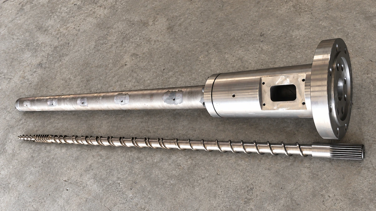
Why Your Single Screw Extruder Design Causes Extrusion Defects
Nov 13, 2026
Learn how single screw extruder design parameters—L/D ratio, compression ratio, channel depth, and mixing elements—affect melt quality, throughput, and defects.
Read Article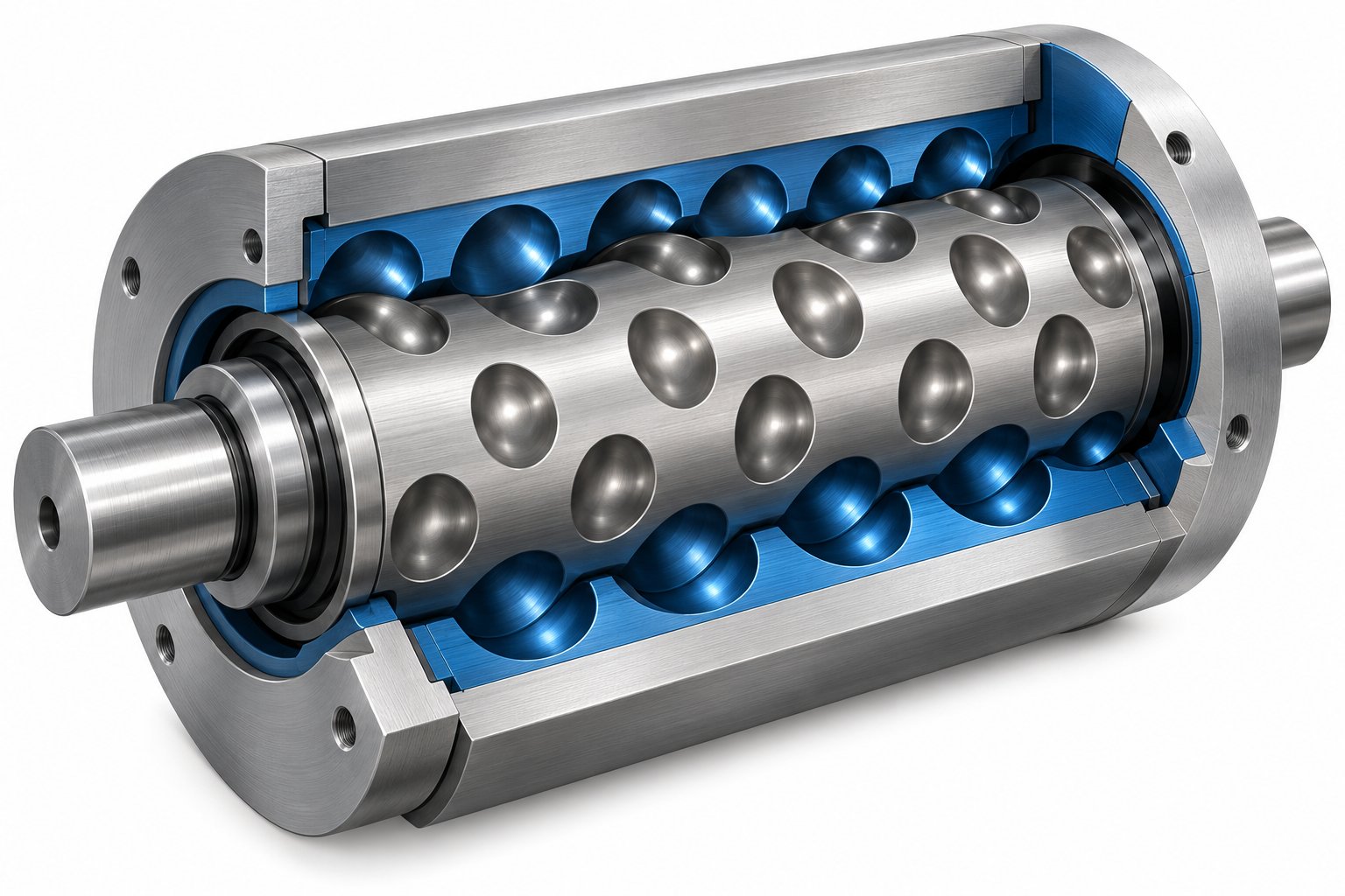
Cavity Transfer Mixer: The Blender Your Extruder Didn't Know It Needed
Nov 13, 2026
Learn how a cavity transfer mixer (CTM) upgrades single-screw extruder mixing. Covers working principles, key parameters, integration, applications, and comparisons.
Read Article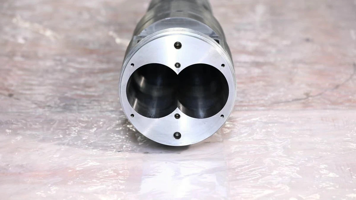
Extruder Barrel Alignment Decoded: Tolerances Most Plants Miss
Nov 13, 2026
Learn extruder barrel alignment tolerances, laser procedures, thermal offsets, and proactive schedules most plants miss — for single-screw and twin-screw lines.
Read ArticleLooking for something else?
Search by material, symptom or product and jump straight to the relevant page.
These are navigation suggestions based on keyword matching — not a quotation, not a delivery commitment, and not a substitute for engineering review. Final specification is confirmed by our engineers against your drawings and processed material.
Need help with screw barrel selection?
Share your machine model, processed material and application. Our team can help with pricing and technical support.