

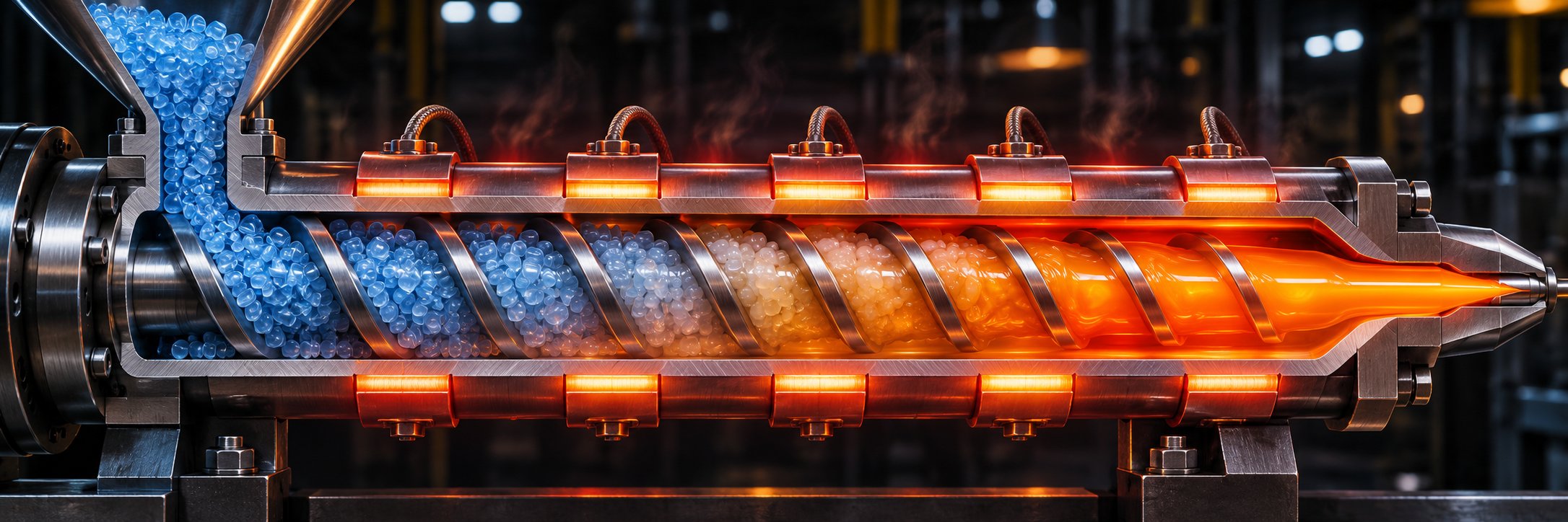
What Is Injection Molding Residence Time
When parts come off the press with black specks, mysterious brittleness, or stubborn discoloration, the mold usually gets the blame first. But more often than most shops realize, the real culprit is hiding inside the barrel. Injection molding residence time is the total duration a given pellet of resin spends inside the heated barrel—from the moment it drops through the feed throat to the moment it exits the nozzle and enters the mold cavity. That span is not one cycle. It covers multiple cycles, because the barrel retains several shots worth of material at any given time.
Injection molding residence time is the total time a resin pellet remains inside the heated barrel, from feed-throat entry to injection into the mold cavity, typically spanning multiple molding cycles.
This distinction trips up even experienced operators. Cycle time measures how long one complete molding sequence takes—injection, pack, hold, cool, open, eject, close. Residence time, by contrast, accounts for the fact that a pellet entering the barrel right now may wait through five, eight, or even more full cycles before it finally reaches the front of the barrel and gets pushed into the cavity. The barrel is essentially a queue, and every pellet must wait its turn.
What Residence Time Means in Practical Terms
Imagine a busy coffee shop with a single-file line. You walk in the door (that is the feed throat), and you can see the counter (the nozzle), but six customers are ahead of you. You will not be served until every one of them completes their order and moves on. Your total time inside the shop is not the time it takes to serve one customer—it is the time it takes to serve all six ahead of you, plus your own transaction. A resin pellet experiences the same thing. It enters the barrel, joins the "queue" of molten and partially molten material, and only exits after enough shots have been fired to push it forward through the full length of the screw and barrel assembly. The number of shots sitting in that queue depends on how large the barrel is relative to each shot's weight—a ratio that changes every time you move a mold to a different press.
Why Every Molder Should Know This Number
Getting this number wrong creates problems on both ends of the spectrum. When residence time runs too long, heat-sensitive polymers endure prolonged thermal exposure that breaks molecular chains, generates gases, and produces the kind of defects that send scrap rates soaring:
- Black specks and carbonized particles from degraded resin
- Splay or silver streaks caused by off-gassing
- Yellowing, discoloration, and brittleness from molecular-weight loss
On the opposite end, residence time that is too short means the resin never fully melts or reaches a uniform melt temperature. You will see unmelted pellets, gels, and inconsistent shot-to-shot quality—problems that no amount of mold adjustment will fix. A commonly accepted target in the industry is between two and five minutes, though high-temperature engineering resins and thermally sensitive materials can demand tighter windows. Whether you are updating the residence address of a mold on your production schedule or quoting a new job, knowing how to evaluate this number is foundational. Much like confirming a booking at the Marriott Residence Inn Portland Airport before a red-eye flight, verifying residence time before production starts saves you from unpleasant surprises down the line. Even a quick check—comparable in effort to looking up directions to Residence Inn Carlisle PA for a weekend trip—can prevent hours of scrap and troubleshooting.
The sections ahead break down exactly how to calculate this value, what machine and process variables shift it, and how to troubleshoot the defects it causes—all from a shop-floor perspective rather than a textbook one.
Why Residence Time Matters for Part Quality and Material Integrity
Here is the uncomfortable truth: you can dial in a textbook-perfect pressure profile, nail your cooling times, and run a beautifully maintained mold—and still produce defective parts if residence time is out of range. That is because every second a polymer spends sitting at barrel temperature is a second of ongoing thermal exposure. Resin molecules do not simply wait patiently; they absorb energy, and past a certain threshold, they start to break apart. This makes injection molding residence time one of the most consequential—and most frequently overlooked—variables on the shop floor.
The Plastics Technology technical community notes that a commonly accepted target falls between two and five minutes. Yet that guideline shifts dramatically depending on the polymer. High-temperature engineering resins like PEEK tolerate longer barrel exposure, while thermally sensitive materials such as PVC and PBT demand much tighter windows. Ignoring these material-specific limits is where quality problems begin.
Thermal Degradation and Its Consequences
Picture a sensitive polymer—PVC, POM, nylon 6/6, or polycarbonate—sitting inside a barrel at processing temperature cycle after cycle. The heat does not simply keep the melt fluid. It drives chemical reactions: molecular-chain scission snaps long polymer chains into shorter, weaker fragments; crosslinking creates unwanted bonds that stiffen the melt unpredictably; off-gassing releases volatile byproducts that become trapped in the melt stream. These are not abstract chemistry lessons. They show up as real defects on real parts, and they cost real money.
Excessive residence time is directly linked to the following quality problems:
- Black specks and carbonized particles — Degraded material carbonizes on barrel walls or in dead spots, then periodically breaks free and contaminates parts.
- Splay or silver streaks — Trapped gases from thermal decomposition create characteristic streaks on the part surface as the melt fills the cavity.
- Discoloration or yellowing — Thermal oxidation changes the polymer's color, especially noticeable in clear or light-colored resins like PC and PMMA.
- Reduced mechanical properties (brittleness) — Molecular-weight loss from chain scission robs the material of its toughness and impact resistance.
- Degraded surface finish — Gas pockets and inconsistent melt viscosity produce rough, pitted, or hazy surfaces that fail cosmetic standards.
As Rosti's processing guide highlights, some of these degradation effects are not immediately visible—weakened parts and inconsistent melt quality can slip past visual inspection, only to fail in end-use testing or in the field. That delayed feedback loop makes the problem even harder to trace back to barrel time if you are not actively tracking it.
Insufficient Residence Time Problems
The flip side is just as damaging, though it looks different on the production floor. When residence time is too short, resin does not spend enough time absorbing heat to reach a fully molten, homogeneous state. You will notice unmelted pellets or gels embedded in finished parts—clear evidence that the material passed through the barrel too quickly for complete plastication. Melt-temperature uniformity suffers as well: some portions of the shot may be at target temperature while others lag behind, producing inconsistent flow behavior and shot-to-shot weight variation. It is a bit like checking into a vacation rental—say, the Hyatt Beach House, a Hyatt Residence Club in Key West, FL—and finding the water heater has not had time to warm up. Everything looks right on the surface, but the experience falls short because the system was not given adequate time to reach steady state.
Packaging applications running on reciprocating-screw machines sometimes push residence times below 1.5 minutes. Industry experts have observed that this duration is often inadequate for elevating semicrystalline plastics like PP and PE to their optimal processing temperatures. In some cases, barrel temperatures have been raised by 100 to 200 degrees Fahrenheit to compensate through conduction—a workaround that introduces its own risks.
The safest starting point? Consult the resin manufacturer's processing datasheet. Every reputable supplier publishes a maximum recommended residence time for its materials—a ceiling you should never exceed without understanding the consequences. These datasheets also specify ideal melt-temperature ranges and barrel-zone settings that, combined with an accurate residence time calculation, form the backbone of a stable process setup. Treat these published limits as non-negotiable guardrails, not suggestions.
Residence time sits at the intersection of material science and machine mechanics—and that intersection is exactly where confusion tends to multiply. Several closely related terms float around the shop floor, and mixing them up leads to misdiagnosis and wasted effort.
Residence Time vs. Cycle Time, Cooling Time, and Dwell Time
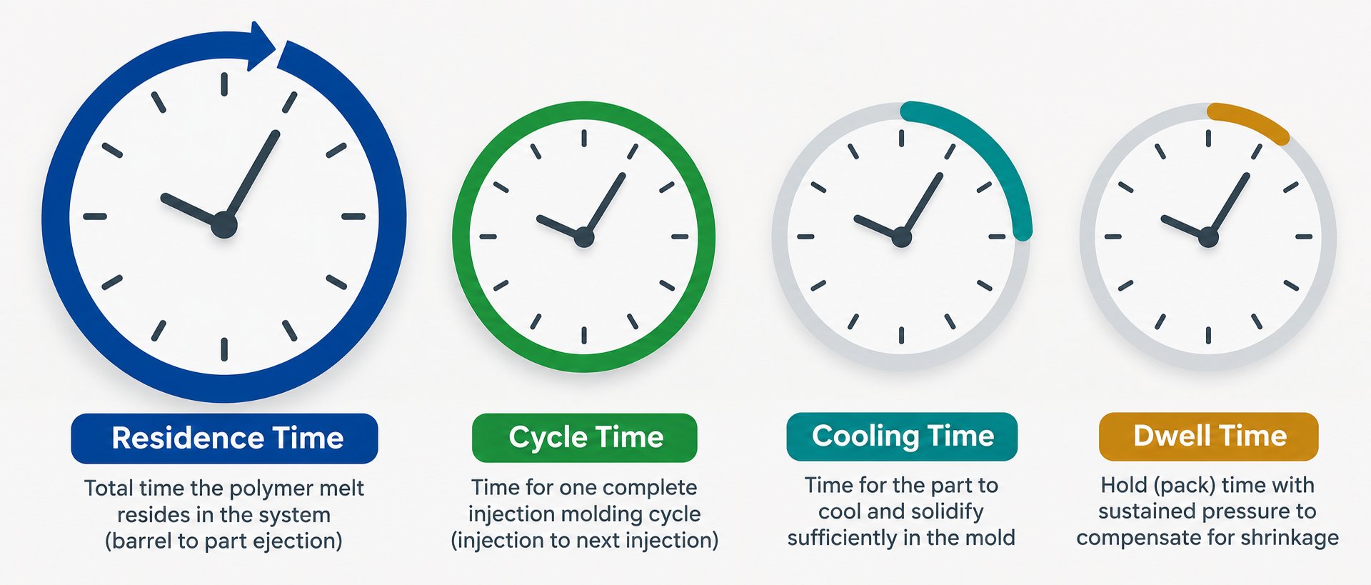
Three terms get tangled up with injection molding residence time more than any others: cycle time, cooling time, and dwell time. On paper they look distinct, but in fast-paced production environments—where verbal shorthand rules—they blur together. Solving the wrong problem because you mistook one term for another is like searching for the Residence Inn by Marriott New York when you actually booked a room at a completely different property across town. Close enough sounds harmless until you end up in the wrong place entirely. Let's untangle each term so you can diagnose issues with precision.
Residence Time vs. Cycle Time
Cycle time is the duration of one complete molding sequence: injection, pack and hold, cooling, mold open, part ejection, and mold close. It measures how long a single shot takes from start to finish. Residence time, on the other hand, spans multiple cycles. It depends on how many shots worth of material the barrel retains at any moment. Think of it this way: if the barrel holds enough resin for six shots and the cycle time is 30 seconds, a pellet entering the feed throat right now will not exit the nozzle for roughly 180 seconds—six cycles later.
Here is the counterintuitive part. A short cycle time does not guarantee a short residence time. If the barrel is significantly oversized relative to the shot weight, the material-to-shot ratio climbs, and pellets queue up through many more cycles than expected. Conversely, a longer cycle time on a well-matched barrel may actually produce a more reasonable residence time than a quick cycle on an oversized press. The ratio of barrel capacity to shot weight is what truly drives the number—not cycle speed alone.
Residence Time vs. Cooling Time
Cooling time is the period during which the molten plastic solidifies inside the mold cavity. It is one component of the overall cycle time—often the longest single phase—and it has no direct equivalence to residence time. However, the two are connected through an indirect chain: longer cooling times stretch the cycle, and a longer cycle multiplies across the number of shots in the barrel to increase total residence time. Adjusting cooling time to improve part quality is common practice, but every added second of cooling also adds a second of thermal exposure for every shot waiting in the barrel queue. That trade-off deserves attention, especially with heat-sensitive resins.
Residence Time vs. Dwell Time
Dwell time creates the most confusion. Some textbooks and shop-floor references use it interchangeably with residence time. Others define dwell time more narrowly as the period the screw remains stationary after recovery is complete—sometimes called soak time. During this window, the material in front of the screw tip sits motionless at barrel temperature, absorbing heat purely through conduction rather than shear. It is a subset of the total residence time, not a synonym for it. Treating the two as identical can lead you to underestimate how long material actually spends at temperature, much like assuming a quick online search for netflix mystery serien will give you the same results as browsing the full catalog—you only see a fraction of the picture.
The table below puts all four terms side by side so you can reference the distinctions at a glance:
| Term | Definition | Scope | Relationship to Residence Time |
|---|---|---|---|
| Residence Time | Total time a resin pellet spends inside the heated barrel, from feed throat to nozzle exit | Spans multiple molding cycles | This is the baseline measurement itself |
| Cycle Time | Duration of one complete molding cycle (inject, pack/hold, cool, open, eject, close) | Single cycle | One multiplier in the residence time formula: Residence Time = (Barrel Capacity / Shot Weight) x Cycle Time |
| Cooling Time | Period the part solidifies inside the mold cavity | One phase within a single cycle | Indirectly affects residence time by influencing total cycle duration |
| Dwell Time (Soak Time) | Time the screw remains stationary after recovery, with material sitting at barrel temperature | One phase within a single cycle | A subset of total residence time; contributes to thermal exposure but does not equal the full value |
Understanding these distinctions matters for practical decision-making. When a technician reports that "residence time is too high," you need to know whether the real issue is an oversized barrel holding too many shots, an inflated cycle time driven by excessive cooling, or extended soak time from slow recovery—because the corrective action is different in each case. Misidentifying the root cause is as unproductive as showing up at Auburn residence halls when your orientation is across campus at Leopold Residence Hall. Close does not count when precision drives the fix.
With the terminology clarified, the natural next question becomes: how do you actually put a number on residence time for your specific machine and mold combination? That requires a straightforward calculation—and a few variables you can pull straight from your machine spec sheet.
How to Calculate Injection Molding Residence Time Step by Step
You have the spec sheet for your machine. You know the weight of your shot. You can read the cycle timer on your press controller. That is all you need. Calculating injection molding residence time is not a lab exercise reserved for process engineers with simulation software—it is a quick, shop-floor-friendly formula that any molder can run in under a minute. The payoff for that minute is knowing, with reasonable confidence, whether your resin is sitting at barrel temperature longer than it should.
The Core Calculation Formula
The standard approach uses three variables you either already know or can look up in seconds:
Residence Time = (Barrel Capacity ÷ Shot Weight) × Cycle Time
Here is what each variable represents:
- Barrel capacity — The maximum shot capacity of the barrel, expressed in grams (or ounces). You will find this on the machine specification sheet, typically listed as the maximum injection volume or shot weight for general-purpose polystyrene (GPPS). If you are running a different resin, material density differences can shift this value—a point Basilius emphasizes when discussing density offsets between GPPS and the actual processing material.
- Shot weight — The total weight of everything injected per cycle: all cavities' parts plus the runner system (cold runner molds) or just the parts (hot runner molds). Weigh a complete shot on a scale for the most accurate figure.
- Cycle time — The duration of one complete molding cycle, from injection start to the next injection start. Read it directly from your press controller.
The ratio inside the parentheses—barrel capacity divided by shot weight—tells you how many shots worth of material the barrel holds at any given moment. That number represents the queue length: the number of cycles a specific pellet of resin must wait through before it finally reaches the nozzle and enters the mold. Multiply that queue length by the cycle time, and you have the total thermal exposure for that pellet.
Worked Example Walkthrough
Sounds abstract? Plug in real numbers and it clicks immediately. Imagine you are setting up a mold on a press with the following parameters:
Barrel capacity: 500 g | Shot weight (parts + runner): 100 g | Cycle time: 30 seconds. Step 1 — Number of shots in barrel: 500 g ÷ 100 g = 5 shots. Step 2 — Residence time: 5 shots × 30 seconds = 150 seconds (2.5 minutes).
That 2.5-minute result means every pellet entering the feed throat right now will spend approximately two and a half minutes inside the heated barrel before being injected into the cavity. For most commodity thermoplastics, 2.5 minutes falls well within acceptable limits. But swap in a heat-sensitive PVC compound with a maximum recommended residence time of 3 minutes and a cycle time that creeps up to 45 seconds due to thick-wall cooling, and the math shifts fast: 5 shots × 45 seconds = 225 seconds (3.75 minutes)—already beyond the resin's published ceiling.
One important nuance: as Basilius notes, barrel capacities are typically specified based on the melt density of GPPS. If you are processing a polymer with a significantly different melt density—say, HDPE, which is less dense in its molten state—the resin occupies more barrel volume per gram. Offsetting for melt density makes the calculation more accurate and can shift barrel utilization and residence time enough to matter. For most day-to-day setups the GPPS-based approximation is a solid starting point, but when you are running materials with densities that diverge sharply from polystyrene, the density correction is worth the extra step.
Interpreting the Result
A number by itself means nothing until you compare it against a benchmark. The benchmark is the resin manufacturer's maximum recommended residence time, published on the material's processing datasheet. If your calculated value sits comfortably below that ceiling, you are in a safe operating window. If it approaches or exceeds the limit, you have identified a problem—and you have identified it before black specks or brittleness show up in your parts.
The residence reviews you conduct at setup are the cheapest quality checks on the production floor. A quick calculation prevents hours of scrap and troubleshooting downstream. Keep the following rules of thumb pinned near your press:
- Barrel utilization between 25% and 65% is the widely recommended sweet spot. Some sources extend the acceptable range to 20–80%, but veteran molding experts like John Bozzelli cap it at 65% to avoid melt-uniformity problems caused by shortened effective feed sections.
- Utilization below 20% signals an oversized barrel. Residence time is almost certainly too long, and thermal degradation risk climbs with every cycle.
- Utilization above 65–80% pushes the screw's feed section behind the feed throat during recovery, starving the transition zone and producing incomplete melting—especially problematic with semi-crystalline resins that require significantly more energy to melt.
- Residence time exceeding the resin datasheet maximum means either the barrel is too large for the shot, the cycle is too long, or both. The corrective path is to move the mold to a smaller press, reduce cycle time, or—if neither is feasible—lower barrel temperatures cautiously while monitoring melt quality.
- Residence time under one minute for most engineering thermoplastics often indicates insufficient thermal exposure, risking unmelted pellets and poor homogeneity.
Think of this calculation the way you would think about checking a booking confirmation—whether at the Residence Inn by Marriott Somerset for a business trip or the Residence on Fifth for a weekend getaway. You verify the details before you arrive, not after you discover a problem at the front desk. Running the residence time formula before locking in a process setup is the same discipline: a small upfront investment that prevents costly surprises.
Of course, the formula gives you one clean number. Reality is messier. Barrel size, screw speed, temperature profiles, and the material itself all push and pull on how long resin actually stays at temperature—and those variables interact in ways a single equation cannot fully capture.
Key Machine and Process Parameters That Influence Residence Time
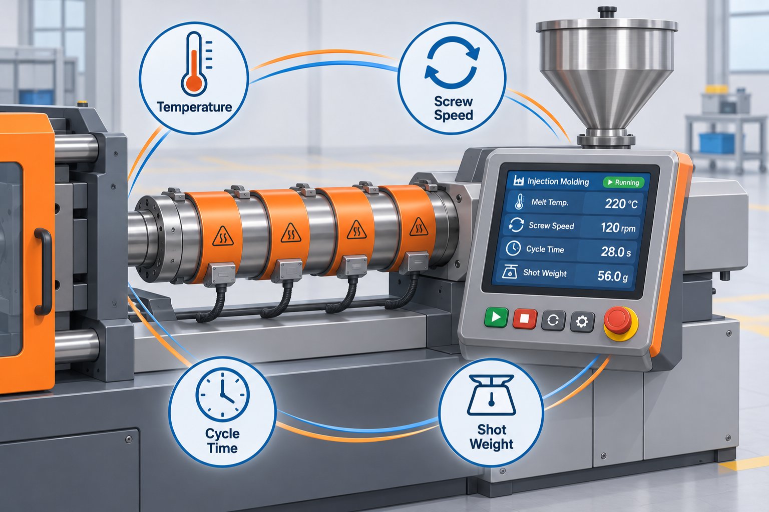
A single formula gives you a residence time estimate, but the real number your resin experiences is shaped by a web of machine settings and process decisions that interact continuously. Change one variable in isolation—say, bump up barrel temperature to speed melting—and you may inadvertently alter screw recovery speed, shift cycle duration, and push effective thermal exposure in a direction you did not intend. Understanding which levers move residence time, and how they influence each other, is what separates a process that runs predictably from one that drifts into defect territory without warning.
Barrel Size and Shot Size Ratio
The single biggest determinant of how many heating cycles a pellet endures is the ratio between the barrel's capacity and the weight of each shot. This relationship is expressed as barrel utilization percentage:
Barrel Utilization (%) = (Shot Weight ÷ Barrel Capacity) × 100
Imagine you are running a mold that produces a 50-gram shot on a machine with a 500-gram barrel capacity. Your utilization is just 10 percent—meaning the barrel holds roughly ten shots of material at any given time. Every pellet waits through ten full cycles before being injected. On a 30-second cycle, that translates to 300 seconds (5 minutes) of thermal exposure. Move the same mold to a press with a 200-gram barrel, and utilization jumps to 25 percent. The barrel now holds only four shots, cutting residence time to 120 seconds (2 minutes). Same mold, same resin, same cycle—dramatically different thermal history.
Industry guidance from Plastics Technology and experienced process engineers generally recommends keeping barrel utilization between 20 and 80 percent per shot. Rosti's processing team tightens that window further, recommending 25 to 65 percent plus an additional 10 percent safety margin. Here is why the boundaries matter:
- Below 20 percent utilization — The barrel is severely oversized for the job. Material queues through far too many heating cycles, and thermally sensitive polymers begin degrading long before they reach the nozzle. This is a common scenario when small molds get assigned to large presses simply because those presses happen to be available.
- Above 80 percent utilization — The screw struggles to recover consistently within the available cycle time. The feed section may retract behind the feed throat during plasticating, starving the compression and metering zones. The result is incomplete melting, poor melt homogeneity, and erratic shot weights—problems that mimic mold issues but actually originate in the barrel.
Barrel utilization is the first parameter to check whenever you assign a mold to a machine, and it deserves as much scrutiny as clamp tonnage or platen size. A press that satisfies every other mechanical requirement can still be the wrong choice if the barrel-to-shot ratio falls outside the workable range.
Cycle Time, Screw Speed, and Temperature Profile
Cycle time has the most straightforward relationship to residence time: it is a direct multiplier. If barrel utilization holds a pellet in queue for six shots and cycle time is 20 seconds, residence time is 120 seconds. Stretch the cycle to 40 seconds—perhaps due to thicker walls requiring longer cooling—and residence time doubles to 240 seconds without a single other parameter changing. Every added second of cooling, packing, mold movement, or robot operation adds that same second of thermal exposure to every shot waiting in the barrel. Unplanned delays are especially dangerous. A semi-automatic press paused for operator intervention can push residence times to 15 minutes or more, which—as industry experts have observed—forces intermittent purging just to clear degraded material, regardless of how well the barrel temperatures are dialed in.
Screw RPM affects residence time more subtly. Faster screw rotation shortens recovery time, which can shave seconds off the overall cycle and reduce thermal exposure. However, higher RPM also generates more shear heat inside the melt, raising the actual plastic temperature independent of the barrel heater setpoints. For shear-sensitive materials, that extra mechanical energy can accelerate degradation even if the calendar time in the barrel is shorter. It is a trade-off: faster recovery reduces residence time, but elevated shear heating raises the effective thermal stress per unit of time.
Barrel temperature profile rounds out the trio. Higher zone temperatures accelerate heat transfer into the resin, which means the material reaches processing temperature sooner and melts more uniformly within a given residence window. That sounds beneficial—and it is, when residence time is on the short side. But when residence time is already long, elevated temperatures compound the damage. Each additional degree accelerates the rate of molecular-chain scission and oxidation. Conversely, lowering barrel temperatures can buy some thermal headroom for oversized-barrel situations, though dropping too far risks incomplete melting and pushes you toward the insufficient-residence-time problems discussed earlier. Much like planning a stay at the Residence Inn by Marriott Hartford Windsor in Windsor, CT, where you weigh proximity against budget and amenities, setting a temperature profile means balancing competing priorities—melting efficiency versus degradation risk—within the constraints your barrel size and cycle time impose.
The table below captures these relationships in a format you can reference quickly during setup or troubleshooting:
| Parameter | Effect When Increased | Effect When Decreased |
|---|---|---|
| Barrel Size (relative to shot) | More shots retained in barrel; longer residence time; higher degradation risk | Fewer shots retained; shorter residence time; risk of incomplete recovery if utilization exceeds 80% |
| Shot Weight | Higher barrel utilization; fewer shots in queue; shorter residence time | Lower barrel utilization; more shots in queue; longer residence time |
| Cycle Time | Directly proportional increase in residence time; greater thermal exposure per shot in queue | Proportional decrease in residence time; less thermal exposure per queued shot |
| Screw RPM | Faster recovery shortens cycle; reduces residence time—but increases shear heat in the melt | Slower recovery lengthens cycle; increases residence time—but lowers shear-generated heat |
| Barrel Temperature | Faster melting and better homogeneity; but accelerates degradation during long residence times | Slower melting may extend required residence; but reduces degradation rate if barrel is oversized |
The critical takeaway from this table is that none of these parameters operates in a vacuum. Raising screw speed to shorten recovery time while simultaneously increasing rear-zone temperature to compensate for reduced conduction time can leave residence time nearly unchanged—yet shift the balance of shear versus conductive heating in ways that affect melt quality. Lowering cycle time by trimming cooling aggressively may reduce barrel exposure but produce parts that warp or have sink marks, sending the mold right back for re-optimization. Every adjustment ripples through the system.
This interconnectedness is precisely why experienced molders treat residence time as a process output rather than a single setting you dial in. It emerges from the combination of barrel size, shot weight, cycle duration, screw behavior, and temperature strategy—all working together. And the most influential of those factors, barrel sizing, is a decision that gets locked in long before the first shot fires. Choosing the right press for the job—or recognizing when the current one is wrong—is the upstream decision that prevents downstream headaches.
Barrel Sizing and Utilization Best Practices for Residence Time Control
Every residence time problem you troubleshoot on the production floor traces back to a decision that was made earlier—often much earlier. That decision is which press to assign the mold to. Clamp tonnage, platen dimensions, and tie-bar spacing get careful scrutiny during mold-to-machine matching. Barrel capacity? It is frequently treated as an afterthought, checked only after degradation defects have already started appearing. Flipping that priority order is the single most effective way to prevent injection molding residence time issues before they consume your scrap budget.
Matching Press Size to Part and Mold Requirements
Evaluating whether a machine is appropriately sized for a mold from a residence time perspective comes down to one ratio: shot weight divided by barrel capacity. If the mold's total shot weight—parts plus runner—uses less than 20 percent of the barrel's rated capacity, the machine is too large for the job. Every pellet entering the feed throat will queue through too many heating cycles, absorbing far more thermal energy than the resin can tolerate. On the other end, if utilization exceeds 80 percent, the screw's feed section retracts behind the feed throat during recovery, starving the transition zone and producing inconsistent melt quality. As John Bozzelli of Injection Molding Solutions has explained, semi-crystalline resins are especially vulnerable in this scenario because they require nearly twice the energy to melt compared to amorphous materials—and a shortened feed section simply cannot deliver it.
Before assigning any mold to a press, run through the following checklist:
- What is the barrel's rated shot capacity? — Pull this from the machine spec sheet. Remember that published values are typically based on general-purpose polystyrene (GPPS); adjust for melt density if running a significantly different polymer.
- What is the total shot weight (parts + runner)? — Weigh a complete shot on a scale rather than relying on CAD-estimated part weights, which often omit runner volume or underestimate packing-phase material.
- What is the target cycle time? — Use a realistic production cycle, not an optimistic estimate. Include any semi-automatic delays, robot handling, or secondary operations that extend the interval between shots.
- What is the resin's maximum allowable residence time? — Find this on the material manufacturer's processing datasheet. It is the hard ceiling your barrel-utilization and cycle-time combination must stay below.
Running these four data points through the standard formula—(Barrel Capacity ÷ Shot Weight) × Cycle Time—gives you the expected residence time in seconds. Compare that result against the resin's published maximum. If the calculated value approaches or exceeds the limit, the press is not the right fit, regardless of how well it satisfies tonnage and platen requirements. Custom molding operations, as Basilius highlights, face this challenge routinely because they run many different molds across a limited fleet of machines, making shot-to-barrel matching a constant balancing act rather than a one-time setup decision.
When Barrel Utilization Signals a Hardware Change
Sometimes the mismatch is not obvious at setup—it reveals itself over weeks or months of production. You might notice a gradual uptick in black specks, a slow drift in part color, or intermittent brittleness that defies process adjustment. These are the fingerprints of chronic over- or under-utilization, and they signal that the barrel environment is working against you rather than with you.
When ongoing production data confirms a persistent barrel-sizing problem, you have three practical options:
- Move the mold to a differently sized machine. This is the most straightforward fix. A press with a smaller barrel brings utilization into range and immediately shortens residence time. It is also the first option to evaluate because it requires no capital investment beyond scheduling logistics. For shops in regions like the Residence Inn Green Bay or Residence Inn Canton areas with concentrated manufacturing bases, swapping molds between presses in a multi-machine facility is routine.
- Adjust the process within the current machine. If a machine change is not feasible—because platen size, tonnage, or availability constraints lock you in—you can partially compensate by reducing barrel temperatures in the rear zones, shortening cycle time where cooling allows, or increasing screw speed to accelerate recovery. These are mitigations, not cures. They narrow the thermal exposure window but cannot fully overcome a fundamentally oversized barrel.
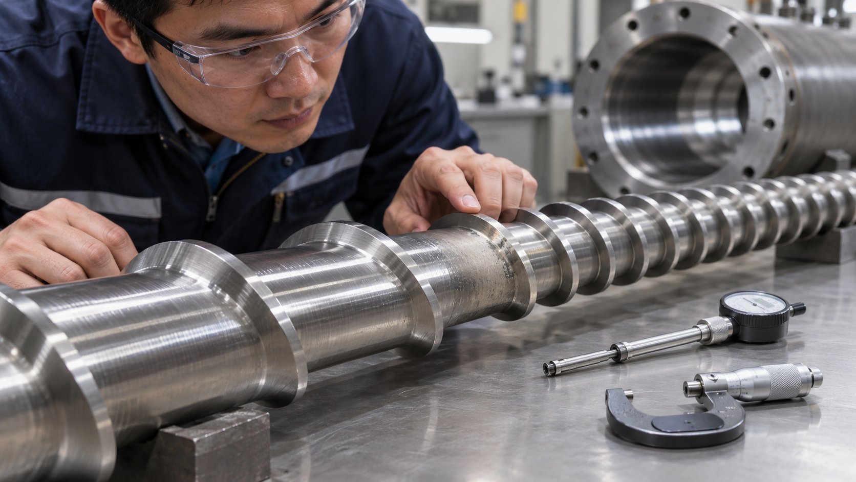
- Evaluate the plasticizing components themselves. The screw-and-barrel assembly directly determines barrel capacity and how uniformly material flows from feed throat to nozzle. Screw geometry—flight depth, compression ratio, transition-zone length, and mixing-section design—shapes the melt channel volume and residence time distribution. In some cases, switching to a screw with a different geometry or a barrel with a smaller bore diameter on the same machine frame can bring utilization into the target window without requiring a full press change. This is a more involved option, but for dedicated production cells running the same resin and mold long-term, it pays dividends in quality consistency, much like how a well-planned stay at the Residence Inn by Marriott Augusta removes logistical friction from a business trip.
For most thermoplastics, the ideal barrel utilization window falls between roughly 25 and 65 percent of rated shot capacity—wide enough to accommodate normal process variation, yet tight enough to keep residence time safely below the resin manufacturer's published maximum.
That 25-to-65-percent range, endorsed by sources including Rosti's scientific molding team and Plastics Technology's process experts, builds in enough margin for shot-to-shot variation, slight cycle-time fluctuations, and material density differences without pushing residence time into the danger zone on either end. Operating at the edges—below 20 percent or above 80 percent—leaves no room for the normal variability that every production run encounters.
Barrel sizing is a hardware decision, and hardware decisions are sticky. Changing a press assignment disrupts scheduling; swapping a screw-and-barrel assembly requires downtime and capital. That stickiness is exactly why getting the match right up front matters so much. A few minutes of calculation during mold assignment prevents weeks of chasing defects that no amount of process tweaking can fully resolve. Yet even a perfectly sized barrel cannot guarantee uniform material flow on its own. How resin actually moves through the screw channel—and where it sometimes stops moving altogether—introduces a layer of complexity that the utilization formula alone does not capture.
FIFO Flow Behavior and Dead Spots Inside the Barrel
The residence time formula from the previous sections gives you a single, tidy number. But resin inside the barrel does not behave like a single, tidy column marching forward in lockstep. In reality, some material moves faster than the average, some moves slower, and a small but destructive fraction barely moves at all. That variation is the difference between the calculated residence time and the actual thermal history your resin experiences—and it explains why perfectly good calculations can still leave you staring at black specks on otherwise flawless parts.
How Material Flows Through the Barrel
In an ideal world, the barrel would operate on strict first-in-first-out (FIFO) principles. The first pellet to drop through the feed throat would be the first to exit the nozzle. Every pellet behind it would follow in perfect order, like passengers boarding a single-aisle airplane and deplaning in reverse. If FIFO held perfectly, residence time would be one fixed value for every molecule in the shot—exactly what the formula predicts.
Real barrels do not work that way. The melt inside the screw channel flows in a laminar profile, not a plug-flow pattern. Material near the center of the channel moves faster, carried along by the drag flow generated between the rotating screw flight and the stationary barrel wall. Material closer to the barrel wall and the screw root moves more slowly, dragged back by friction and boundary-layer effects. The result is a residence time distribution rather than a single value: some portion of the melt exits sooner than the calculated average, and some portion lingers considerably longer.
Screw geometry amplifies this spread. The depth of the feed section, the compression ratio through the transition zone, and the design of any mixing elements all influence how uniformly resin advances from rear to front. A screw with aggressive compression and shallow metering channels tends to push material forward more evenly, narrowing the distribution. A worn screw with eroded flight edges or inconsistent channel depths widens it, allowing some resin to recirculate or stall while the bulk stream passes by. As Plastics Technology details, even factors like backpressure and the percentage of barrel capacity in use change how much molten plastic sits on the screw at any moment—shifting the distribution in ways the simple shot-count formula cannot capture.
For practical purposes, this means the number your formula produces is a useful average, not a guarantee. Some resin in every shot spent less time at temperature than the calculated figure suggests. And some spent meaningfully more. When that "more" exceeds the resin's thermal tolerance, degradation products form—even though the average residence time looked perfectly safe on paper.
Dead Spots and Material Hang-Up
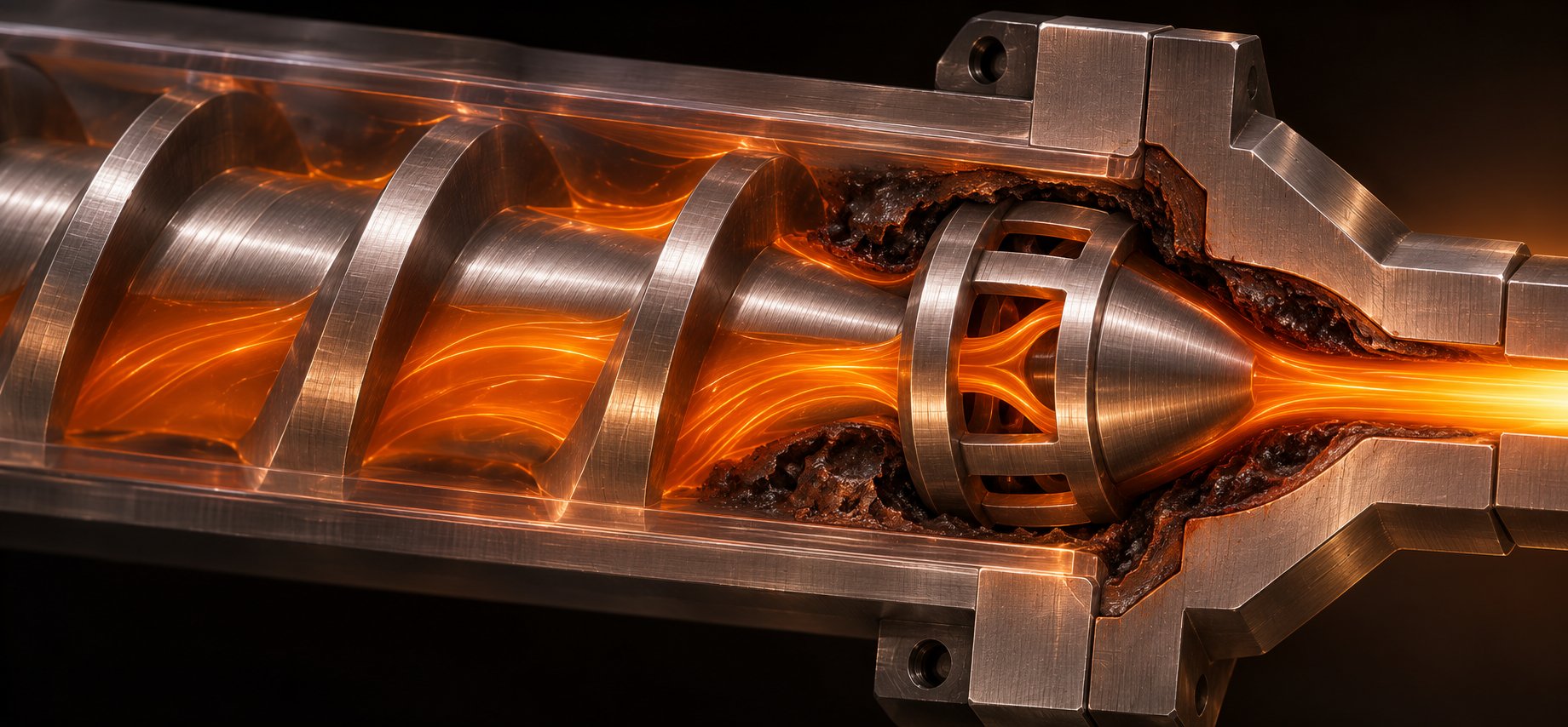
If residence time distribution is the expected spread around an average, dead spots are the extreme outliers—pockets where resin stagnates for minutes or even hours beyond what any calculation would predict. Imagine a slow eddy in a river where leaves collect and spin instead of flowing downstream. Inside the barrel and its associated hardware, dead spots trap small volumes of melt in areas with little or no flow, subjecting that material to relentless thermal exposure far exceeding the normal processing window.
What happens to stagnant resin? It degrades. Molecular chains break. Volatile gases form. The material carbonizes into hard, blackened residue that clings to metal surfaces until shear forces or pressure fluctuations eventually dislodge a fragment. That fragment enters the melt stream and shows up in a finished part as a black speck, a brown streak, or a carbonized particle embedded in an otherwise clean surface. As CK Mold's diagnostic guide explains, these degradation-sourced specks typically appear as streaky, brownish-black marks that are smeared and fused into the base plastic—visually distinct from foreign contamination, which tends to have sharp edges and a clearly defined boundary.
The frustrating part? Dead-spot contamination is intermittent. Parts may run clean for dozens or hundreds of shots, then a burst of specks appears without any process change. That randomness sends troubleshooting teams chasing phantom mold issues, material lot variations, or operator errors when the real source is a tiny pocket of carbonized resin that has been quietly cooking inside the barrel assembly all along. The residence show of material flowing through the barrel looks orderly on the surface, but hidden stagnation zones tell a very different story.
Dead spots develop in predictable locations. Knowing where to look converts a vague suspicion into a targeted inspection:
- Check-ring (non-return valve) assembly — Worn or damaged check rings create gaps where melt pools behind the ring seat, trapped outside the normal flow path. MD Plastics notes that backflow from worn non-return valves is a recognized equipment safety and quality risk, introducing stagnant material into fresh shots.
- Nozzle tip and adapter — Sharp internal corners, oversized bores, or mismatched thread connections between the nozzle body and tip create recesses where resin sits motionless at full barrel temperature.
- Barrel-to-nozzle junction — Any misalignment or step in the bore diameter at this transition acts as a shelf that traps melt. Even a fraction of a millimeter of mismatch creates enough dead volume for carbonization to begin.
- Worn or corroded screw-flight lands — When the outer edge of a screw flight wears down, the clearance between the flight and the barrel wall increases. Melt leaks backward over the flight instead of being pushed forward, creating localized stagnation zones along the screw length. Sharp corners where flights meet the screw root compound the problem—as industry screw-design references emphasize, a smooth corner radius at the flight root helps melt flow completely through the channel, while sharp edges trap material and accelerate degradation.
Regular inspection and maintenance of the screw-and-barrel assembly is the primary defense against dead spots. Pull the screw periodically and examine the flight edges for wear, the check ring for sealing integrity, and the barrel bore for scoring or corrosion. Inspect the nozzle internals for carbon buildup or bore-diameter mismatches. These checks are not glamorous, but they catch stagnation problems before intermittent specks escalate into chronic contamination—much like how a traveler checking reviews for the Residence Inn Austin Southwest or the Portland Maine Residence Inn Marriott before booking avoids unpleasant surprises that only surface after arrival.
Dead spots inflate effective residence time in ways the standard formula cannot predict. They turn a theoretically safe barrel-utilization ratio into a real-world degradation source, and they do it silently until a carbonized fragment finally breaks free. That silent, intermittent nature is exactly what makes dead-spot defects so easy to misdiagnose—and why a structured troubleshooting framework, rather than guesswork, is essential when degradation symptoms appear on your parts.
Troubleshooting Defects Caused by Excessive or Insufficient Residence Time
A black speck shows up on a part. Then another. Then a silver streak. The instinct on most shop floors is to pull the mold and start inspecting gates, vents, and cavity surfaces. Sometimes that is exactly the right call. But when the defect pattern points to degradation rather than fill or packing issues, the mold is not your problem—the barrel is. The challenge is telling the difference, because degradation defects can mimic other root causes convincingly enough to send a team down the wrong troubleshooting path for hours.
Having a structured diagnostic framework—one that connects the visual signature of a defect to its likely residence time cause and a specific corrective action—strips the guesswork out of the process. Think of it as a field guide: when you see a symptom, you match it against known patterns instead of chasing theories. The residence filmed on camera during mold trials rarely captures what is happening inside the barrel, so you need these external clues to infer internal conditions.
Identifying Degradation-Related Defects
Degradation from excessive injection molding residence time leaves distinct fingerprints on parts. Some are immediately obvious; others only reveal themselves under closer inspection or mechanical testing. Here are the most common symptoms and what they tell you:
- Black specks and brown streaks — Carbonized material dislodged from dead spots, worn check rings, or barrel-wall deposits. These appear as dark inclusions smeared into the part surface, often with an irregular, elongated shape.
- Splay or silver streaks — Volatile gases released by thermally degrading resin get trapped in the melt front and leave characteristic silvery, fan-shaped streaks on the part surface as the cavity fills.
- Yellowing or discoloration — Thermal oxidation shifts the resin's color, particularly noticeable in transparent, white, or light-colored materials like polycarbonate and PMMA. The shift can be subtle—easy to miss without a color standard for comparison.
- Brittleness and reduced impact strength — Molecular-weight loss from chain scission robs the polymer of toughness. Parts may look fine visually yet fracture under loads the material should handle easily. This is the most dangerous degradation symptom because it is invisible until a part fails in service.
- Rough or pitted surface finish — Gas pockets from decomposition and inconsistent melt viscosity produce surface irregularities that no amount of mold polishing will eliminate.
The table below maps each defect to its visual appearance, the most likely residence time root cause, and the corrective action to pursue first. Pin this near your press as a quick-reference diagnostic tool:
| Defect | Visual Appearance | Likely Residence Time Cause | Corrective Action |
|---|---|---|---|
| Black specks / brown streaks | Dark, irregular inclusions smeared into the part; often elongated or streaky | Excessive residence time causing carbonization in dead spots or on barrel walls | Inspect check ring, nozzle, and barrel bore for hang-up zones; purge thoroughly; verify barrel utilization is above 20% |
| Splay / silver streaks | Silvery, fan-shaped marks radiating from the gate across the part surface | Off-gassing from thermally degrading resin sitting at temperature too long | Recalculate residence time against resin datasheet maximum; reduce barrel temperatures in rear zones; rule out moisture first |
| Yellowing / discoloration | Gradual color shift toward yellow, amber, or brown compared to the color standard | Thermal oxidation from prolonged barrel exposure, especially in rear and transition zones | Move mold to a smaller press to reduce barrel utilization ratio; lower melt temperature; shorten cycle time if possible |
| Brittleness / low impact strength | No visible surface defect; parts fracture unexpectedly under normal loads or drop tests | Molecular-weight loss from chain scission during extended thermal exposure | Verify residence time is within resin supplier's published limit; check for unplanned cycle delays inflating barrel time |
| Rough / pitted surface | Hazy, orange-peel, or micro-pitted finish inconsistent with mold surface quality | Gas entrapment from decomposition byproducts; viscosity inconsistency from partial degradation | Review barrel temperature profile for excessively high rear-zone settings; inspect screw flights for wear that creates stagnation |
One critical note before you start matching symptoms: not every defect on this list is exclusively caused by residence time. Splay can also result from moisture in the resin. Black specks can originate from contaminated regrind. Brittleness can stem from incorrect material selection or over-drying. The table points you toward residence time as a likely cause, but confirmation requires working through the corrective sequence below rather than jumping to conclusions.
Systematic Corrective Actions
When degradation symptoms appear, resist the urge to change three settings at once. A scattershot approach might accidentally fix the problem—but you will never know which change actually worked, leaving you vulnerable to a repeat. Instead, follow a prioritized sequence that moves from the fastest, lowest-cost checks to more involved investigations:
- Verify the calculated residence time against the resin datasheet maximum. Run the formula—(Barrel Capacity ÷ Shot Weight) × Cycle Time—and compare the result to the supplier's published ceiling. If you are already over the limit, you have found the primary driver. This takes less than a minute and costs nothing.
- Check barrel utilization—is the machine oversized for the shot? Calculate shot weight as a percentage of barrel capacity. If utilization falls below 20 percent, the barrel is holding far too many shots of material and every pellet endures excessive thermal exposure. The fix is a press change, not a process tweak.
- Investigate cycle time—are there unplanned delays inflating residence? Semi-automatic operation, slow robots, upstream feed interruptions, and operator-paced steps can inflate actual cycle time well beyond the programmed value. Log real cycle times over a production run rather than relying on the controller's target setting. Even a few extra seconds per cycle, multiplied across the number of shots in the barrel, can push residence time past the resin's tolerance.
- Inspect the screw, check ring, and barrel for wear or hang-up zones. Pull the screw and examine flight edges, the check-ring seat, the nozzle bore, and the barrel-to-nozzle junction. Worn components create dead volume that the formula does not account for—pockets where material stagnates and carbonizes regardless of what your calculated residence time says.
- Review the barrel temperature profile for unnecessarily high rear-zone settings. Rear-zone temperatures that are set higher than the resin requires accelerate degradation in the section of the barrel where material has the longest remaining exposure time. Lowering rear-zone heat can buy meaningful thermal headroom without sacrificing melt quality at the nozzle.
- Evaluate whether proper purging procedures are being followed during material changes and downtime. Degraded material trapped in dead spots from a previous run or from an extended shutdown contaminates fresh resin if it is not purged out effectively. A quick visual purge is not always sufficient—Asaclean's processing experts note that material degradation worsens significantly when proper drying and purging protocols are not followed, especially when regrind of questionable quality is reintroduced into the system.
Working through these six steps in order gives you the highest probability of isolating the true root cause with the least wasted effort. Steps one through three are pure data checks—no tools required, no downtime incurred. Steps four through six involve progressively more hands-on investigation but are only necessary when the data checks alone do not resolve the issue.
Equally important: know when residence time is not the culprit. Defects like flash, short shots, and sink marks originate from mold geometry, venting, clamp force, or packing-pressure profiles—not barrel exposure. Attributing those symptoms to residence time without evidence sends troubleshooting in the wrong direction and delays the actual fix. A residence inn in Oceanside will not help you if your destination is inland; similarly, a residence time investigation will not solve a problem rooted in inadequate venting or insufficient pack pressure. Match the diagnostic to the symptom, follow the evidence, and let the data—not assumption—guide the corrective action.
Solving a one-time defect outbreak is satisfying. Preventing it from recurring is the real goal. That shift from reactive troubleshooting to proactive control depends on three ongoing disciplines: how you purge, how you maintain your screw and barrel, and how you manage material retention across production runs and shutdowns.
Purging, Screw-Barrel Maintenance, and Long-Term Residence Time Control
Catching a degradation defect and tracing it back to residence time is valuable. Preventing it from happening again is where the real savings live. The troubleshooting sequence from the previous section works when something has already gone wrong. The disciplines covered here—purging protocols, screw-and-barrel condition monitoring, and material-retention management—work continuously in the background to keep injection molding residence time within safe limits across every shift, every material change, and every unplanned interruption. Think of them as the maintenance equivalent of checking smoke detectors before a fire starts rather than shopping for extinguishers after one breaks out.
Purging Protocols and Residence Time Management
Purging is not just a housekeeping step between color changes. From a residence time perspective, it is the only tool that clears stagnant material from hang-up areas that normal shot cycles cannot reach. Every dead spot identified earlier in this article—check-ring recesses, nozzle-tip pockets, barrel-to-nozzle junctions, worn flight clearances—accumulates degraded resin during production. The normal melt stream flows past these zones without flushing them. Only a deliberate purge, at higher-than-production screw speeds and pressures, generates enough turbulence and displacement to sweep stagnant material out of those hidden pockets.
Three scenarios demand purging from a residence time standpoint:
- Extended downtime. If the machine sits idle at barrel temperature for longer than the resin's maximum recommended residence time—whether due to a lunch break, a maintenance call, or an overnight hold—the material inside has been cooking well past its thermal tolerance. Every gram of that resin is now degraded to some degree. Restarting production without purging pushes carbonized, chain-scissioned material directly into the next several shots. Aprios' scientific molding team treats idle time as a tracked parameter, prompting automatic purging when limits are exceeded—an approach that removes human judgment from a decision that should be non-negotiable.
- Material or color changes. Old resin trapped in dead spots contaminates the new run long after the bulk material has transitioned. You might see clean parts for the first fifty shots, then a stray streak of the previous color appears—dislodged from a nozzle recess or check-ring gap hours into the new run. Thorough purging before the changeover, followed by a secondary purge after the new resin has had time to heat-soak, minimizes this cross-contamination risk.
- Startup after overnight shutdown. Material left in the barrel overnight—even with heaters turned off—experiences a slow thermal cycle as the barrel cools and reheats. That thermal cycling degrades the polymer differently than steady-state processing, often producing a mix of partially carbonized and oxidized material. A startup purge clears this compromised resin before production parts begin.
Effective purging is not simply running the screw until the extrudate looks clean. Dead spots release trapped material intermittently, so a visually clear purge stream does not guarantee that all stagnant resin has been displaced. Using a purging compound—formulated to scrub barrel walls and penetrate tight clearances more aggressively than production resin—improves the odds. So does varying screw speed and backpressure during the purge cycle to change flow patterns and dislodge material from different zones. Some facilities standardize purge quantities by barrel capacity, specifying, for example, that a minimum of three full barrel volumes must be displaced before resuming production. That kind of documented, repeatable procedure eliminates guesswork and ensures consistency regardless of which operator runs the press.
Screw and Barrel Condition as a Residence Time Variable
You can follow every purging protocol perfectly and still fight residence time problems if the screw and barrel themselves have deteriorated. Worn hardware creates uncontrolled dead volume—volume the formula does not account for—that inflates effective thermal exposure beyond what your calculations predict. The gap between calculated and actual residence time widens silently as components wear, which is why periodic inspection is essential rather than optional.
Here is how each type of wear contributes to the problem:
- Worn screw flights. As the outer edge of a flight wears down, the clearance between the flight and the barrel wall increases. Melt leaks backward over the worn flight instead of being pushed forward, creating localized stagnation along the screw length. The affected material experiences residence times far exceeding the barrel average. As Plastics Technology's technical analysis points out, even the screw geometry factors—compression ratio, flight depth, and L/D ratio—interact with residence time in ways that a simple shot-count equation cannot fully capture. Worn flights amplify that uncertainty.
- Eroded check rings (non-return valves). A check ring that no longer seals properly allows melt to shuttle back and forth across the ring seat during injection and recovery. Material trapped in the gap between the ring and the screw tip circulates without advancing, accumulating thermal exposure with every cycle.
- Scored barrel bores. Scratches, corrosion pits, or erosion grooves on the barrel's inner surface act as micro-pockets that trap thin films of resin. These films carbonize in place, periodically flaking off into the melt stream as black specks or carbon particles. A barrel bore that measures within tolerance on a diameter check can still harbor surface damage that creates hang-up zones invisible to calipers.
Screw geometry is not just a wear concern—it is a design concern. Compression ratio, flight depth, transition-zone length, and mixing-section configuration collectively determine how uniformly material advances through the barrel. A screw designed for a general-purpose resin may create flow dead zones when running a high-viscosity engineering polymer, simply because the channel geometry does not match the material's rheological behavior. Conversely, an aggressively designed mixing section might work beautifully for color dispersion but create recirculation zones that extend residence time for thermally sensitive resins.
When inspection reveals wear or geometry-related retention issues, replacing the screw-barrel assembly with components engineered for the specific machine, resin, and shot requirements can restore proper residence time control. NANHAIYA's custom injection molding screw barrels offer one tailored option—their technical review considers screw geometry, wear patterns, melting efficiency, mixing performance, and material-retention concerns to match the screw and barrel to the application. This kind of application-specific matching addresses not just dimensional wear but also the flow-path design that determines whether material moves uniformly or stagnates in hidden pockets. It is one component of a comprehensive residence time management strategy—not a standalone fix, but a meaningful upstream improvement that makes downstream process control more predictable.
Regardless of who supplies the hardware, the following maintenance checkpoints should be part of every preventive-maintenance schedule. Treat them the way a frequent traveler would treat confirming a reservation at the Residence Inn New York Manhattan Central Park before a critical meeting—skipping the verification feels like a time-saver until it costs you far more than the check would have:
- Check-ring sealing: Perform a check-ring leak test (decompression/hold-pressure decay) at regular intervals. A ring that passes today can fail next month as wear progresses.
- Flight-edge sharpness: Measure flight OD at multiple points along the screw length. Compare against the original specification. Wear exceeding 0.05 mm per side on the flight land warrants evaluation for replacement.
- Barrel bore diameter measurement: Use a bore gauge to measure at the feed, transition, and metering zones. Localized wear in the transition zone—where pressures and temperatures peak—is the most common pattern and the most consequential for stagnation.
- Nozzle-tip inspection: Check the nozzle bore for carbon buildup, diameter changes from erosion, and proper seating against the sprue bushing. A misaligned or eroded nozzle tip is one of the most overlooked dead-spot sources on the shop floor.
Documenting these measurements over time creates a wear-trend baseline that lets you predict replacement timing rather than reacting to defects. A residence51-style approach—systematic, data-driven, and repeatable—turns screw-and-barrel maintenance from a reactive emergency into a planned activity. Facilities that track bore diameter and flight wear the way financial teams track quarterly numbers catch problems months before those problems reach the parts. Similarly, operations near destinations like the Residence Inn National Mall that serve high-volume government or defense contracts often adopt this kind of proactive documentation because the cost of a field failure dwarfs the cost of a scheduled inspection.
Purging clears the barrel. Inspection catches the wear. Proper screw-barrel geometry ensures uniform flow. Together, these three disciplines close the gap between calculated residence time and actual residence time—the gap where degradation hides. No single action eliminates the risk entirely. But layering these practices into your standard operating procedures transforms residence time from an invisible variable that ambushes production into a controlled parameter you can measure, predict, and manage with confidence.
Frequently Asked Questions About Injection Molding Residence Time
1. What is a good residence time for injection molding?
Most thermoplastics perform well with a residence time between two and five minutes, but the ideal value depends on the specific polymer. Heat-sensitive resins like PVC and POM require shorter barrel exposure, sometimes under three minutes, while high-temperature engineering plastics such as PEEK tolerate longer durations. Always check the resin manufacturer's processing datasheet for the published maximum residence time and keep your calculated value safely below that ceiling. Barrel utilization between 25% and 65% of rated shot capacity generally keeps residence time within a safe window for the majority of commodity and engineering resins.
2. How do you calculate residence time in an injection molding machine?
Use the formula: Residence Time = (Barrel Capacity / Shot Weight) x Cycle Time. Barrel capacity in grams comes from your machine spec sheet, shot weight is the total weight of parts plus runner per cycle, and cycle time is the full duration of one molding sequence. For example, a 500 g barrel capacity with a 100 g shot weight and a 30-second cycle yields 5 shots in the barrel multiplied by 30 seconds, equaling 150 seconds or 2.5 minutes. Note that published barrel capacities are typically based on GPPS density, so adjusting for the melt density of your actual resin improves accuracy.
3. What is the difference between residence time and cycle time in injection molding?
Cycle time measures the duration of a single molding sequence from injection start to the next injection start. Residence time spans multiple cycles and represents the total time a resin pellet stays inside the heated barrel before being injected. A barrel that holds six shots of material means each pellet waits through six full cycles. A short cycle time does not guarantee short residence time if the barrel is oversized relative to the shot weight, because the pellet still queues through many heating cycles before reaching the nozzle.
4. What causes black specks in injection molded parts?
Black specks are most commonly caused by carbonized resin that has stagnated in dead spots inside the barrel assembly. Worn check rings, damaged nozzle tips, barrel-to-nozzle misalignment, and eroded screw flights create pockets where melt sits motionless at processing temperature far longer than the calculated average residence time. This trapped material degrades and carbonizes, then periodically breaks free and contaminates parts. Regular screw pulls, check-ring inspections, and thorough purging protocols are the primary defenses. Replacing worn plasticizing components, such as custom-engineered screw barrels from suppliers like NANHAIYA, can also restore proper flow paths and eliminate hidden hang-up zones.
5. What barrel utilization percentage is recommended for injection molding?
Industry experts recommend keeping barrel utilization between 25% and 65% of rated shot capacity for most thermoplastics. Utilization below 20% means the barrel is oversized for the job, trapping resin through too many heating cycles and driving excessive residence time. Utilization above 80% risks incomplete screw recovery and inconsistent melt quality, especially with semi-crystalline resins that demand high melting energy. Calculating utilization is straightforward: divide total shot weight by barrel capacity and multiply by 100. Checking this ratio before assigning a mold to a press prevents degradation issues before they start.
Written by
Nanhaiya Technical Team
Zhoushan Nanhaiya Plastic Machinery Co., Ltd.
The Nanhaiya technical team supports screw and barrel manufacturing projects through application review, technical communication, custom manufacturing coordination, and production and quality control.
Discuss Your Application
Related Articles
More insights on screw barrel technology and plastics processing.

Injection Molding Color Mixing: From Streaks to Flawless Consistency
Nov 19, 2026
Master injection molding color mixing with expert guidance on colorant types, screw design, process parameters, defect troubleshooting, and Delta E QC protocols.
Read Article
Wrong Extruder Breaker Plate? Spot the Signs Before Scrap Piles Up
Nov 19, 2026
Learn how to select, size, and maintain your extruder breaker plate. Covers hole geometry, pressure drop, polymer-specific specs, and troubleshooting tips.
Read Article
Injection Molding Melt Temperature: Why Your Barrel Settings Lie
Nov 19, 2026
Learn why barrel set points lie about injection molding melt temperature. Complete resin chart, measurement methods, defect troubleshooting, and optimization steps.
Read ArticleLooking for something else?
Search by material, symptom or product and jump straight to the relevant page.
These are navigation suggestions based on keyword matching — not a quotation, not a delivery commitment, and not a substitute for engineering review. Final specification is confirmed by our engineers against your drawings and processed material.
Need help with screw barrel selection?
Share your machine model, processed material and application. Our team can help with pricing and technical support.