

What Injection Molding Screw Types Are and Why They Matter
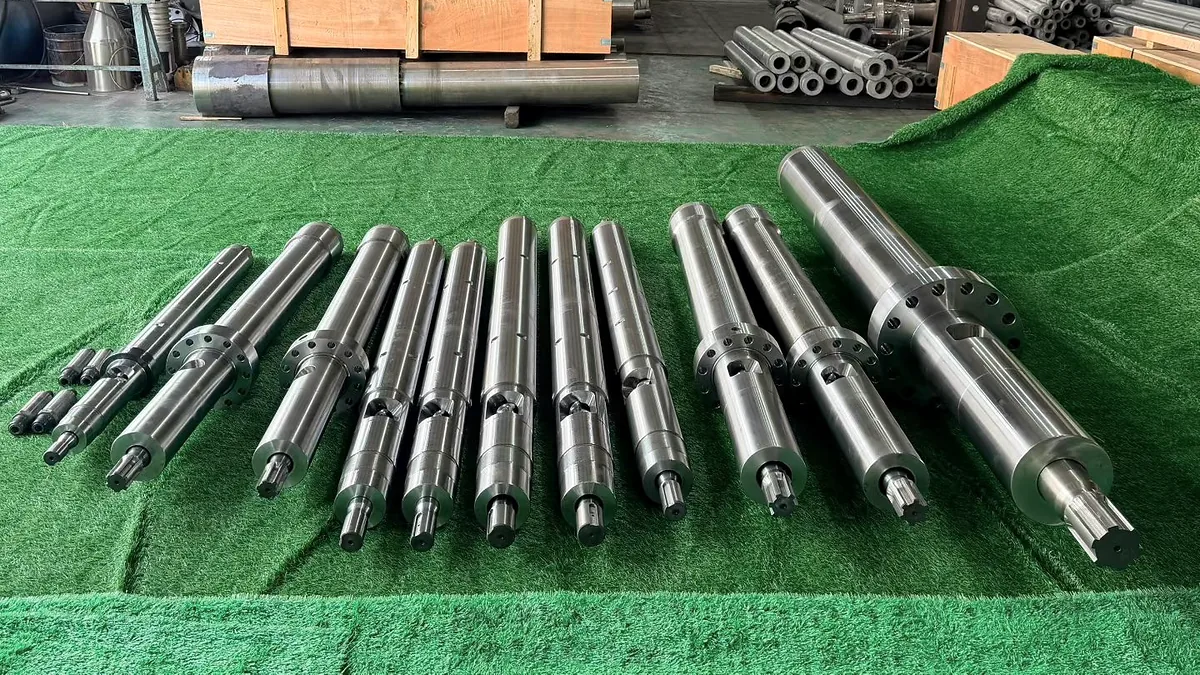
Injection molding screw types refer to the distinct categories of helical screws — general-purpose, barrier, mixing, and vented — each engineered with specific flight geometries, compression ratios, and zone configurations to plasticize different polymers under different processing demands. The screw sits inside the heated barrel of a screw type injection molding machine, and it is the single component most responsible for converting raw plastic pellets into a uniform, injectable melt.
That distinction matters more than most operators realize. Your mold can be flawless. Your clamp tonnage can be perfectly sized. But if the screw delivers an inconsistent melt — with temperature variations, unmelted particles, or poorly dispersed additives — every downstream parameter suffers. Scrap climbs, cycle times stretch, and defect troubleshooting becomes a guessing game.
This guide is built around two navigation paths. You can explore by screw design category — from general-purpose baselines through barrier, mixing, and vented configurations — or you can enter by practical application, matching the resin you run, the defect you're chasing, or the process type you operate. Either path leads to the same destination: a clear, engineering-grounded match between your plasticizing needs and the right screw geometry.
The injection molding screw simultaneously conveys, compresses, melts, mixes, and meters resin in a single rotating element — no other component in the entire molding cell performs this many critical functions at once.
Why the Screw Is the Heart of Plasticizing Performance
Imagine trying to bake with ingredients that aren't fully blended. You'd get pockets of raw flour, uneven texture, and unpredictable results. The types of screw in injection molding solve essentially the same problem — they must take solid granules and deliver a perfectly homogenous melt, shot after shot. Barrel heaters supply external energy, but it's the screw's mechanical action — shearing, compressing, and pumping the polymer along its flights — that generates roughly 60% to 80% of the heat needed for melting in many applications. Screw speed, back pressure, and flight geometry all determine how completely and uniformly this conversion happens before the screw plunges forward to inject.
How Screw Design Evolved From Plunger to Reciprocating Systems
The earliest injection molding machines relied entirely on plunger injection. A ram pushed cold pellets through a heated barrel, relying on conduction from barrel walls and a stationary "torpedo" spreader to melt the material. The result was poor temperature uniformity, limited mixing capability, and no real homogenization. Processors fought inconsistent viscosity, high injection pressures, and sluggish color changes.
The reciprocating screw, commercialized in the late 1950s, changed everything. William Willert developed the concept in 1952, and by the early 1960s nearly every major machinery builder offered a screw type injection molding machine. The reciprocating screw delivered homogenous melt with close temperature control and uniform viscosity — enabling up to 50% faster production rates than screw plunger type injection molding systems. It also reduced required injection pressures because resin arrived at the mold fully melted rather than partially softened.
Yet the early general-purpose reciprocating screw was a compromise — adequate for commodity resins but limited when processors pushed throughput boundaries or switched to engineering polymers. Those limitations sparked the development of every specialized screw category covered in this article: barrier flights for more controlled melting, mixing elements for better homogeneity, and vented two-stage designs for degassing moisture-sensitive materials. Each innovation addressed a specific shortcoming that the original three-zone design couldn't overcome on its own.
Before diving into those specialized designs, though, you'll need a shared vocabulary — the geometry parameters and functional zones that define every screw, regardless of type.
Screw Geometry Fundamentals That Drive Performance
Every injection molding screw type — whether a basic three-zone design or a highly specialized barrier configuration — is defined by the same set of geometry parameters. Change one dimension, and you shift the balance between melt quality, throughput capacity, and shear heat generation. Understanding these parameters gives you a universal language for evaluating any screw and predicting how it will behave with a given resin. Think of it this way: you wouldn't select a cutting tool without knowing its flute geometry. The same discipline applies here.
Feed, Transition, and Metering Zones Explained
Regardless of the injection molding screw type you're examining, the flighted length divides into three functional zones, each with a distinct job:
- Feed zone: The deepest section of the screw, located directly beneath the hopper. Its constant, deep channel accepts solid pellets and conveys them forward. The generous flight depth here maximizes intake volume so the screw can maintain consistent throughput. On a standard general-purpose (GP) screw, the feed zone typically occupies around 50% of the total flighted length.
- Transition (compression) zone: Here, the channel depth decreases progressively — imagine the walls gradually closing in on the plastic. This shrinking volume compresses the softening pellets, squeezes out trapped air back toward the hopper, and generates the frictional and shear heat that drives melting. A GP screw usually dedicates roughly 30% of its length to this zone.
- Metering zone: The shallowest and final section, with a constant, shallow channel depth. By this point, the resin should be fully melted. The metering zone's job is to homogenize the melt temperature, stabilize pressure, and deliver a uniform output to the screw tip. It typically makes up the remaining 20% of a GP screw's length.
These zone proportions are far from fixed across different types of injection molding screws. Semi-crystalline polymers like nylon (PA) and PBT, which have sharp melting points and melt quickly once they reach that temperature, often perform best on screws with a longer feed zone (around 60%) and a shorter, more abrupt compression zone (around 20%). Heat-sensitive materials like PVC call for an extended compression zone (up to 40%) with a very gradual taper to avoid localized overheating. The zone ratio is one of the first clues that tells you what resin family a screw was designed to process.
Key Geometry Parameters That Control Melt Quality
Beyond zone lengths, several measurable dimensions work together to determine how aggressively or gently a screw plasticizes resin:
- Flight depth (channel depth): The distance from the screw root to the top of the flight. Deep channels in the feed zone maximize solids intake; shallow channels in the metering zone increase shear and improve mixing. For GP screws, feed depth typically falls in the range of 0.12D to 0.14D (where D is the screw's nominal diameter), while metering depth runs from 0.05D to 0.07D.
- Pitch: The axial distance from one flight to the next. Most injection molding screws use a square pitch, meaning the pitch equals the screw diameter (1D). This standard simplifies L/D calculations — you can estimate L/D simply by counting the number of flight turns.
- Helix angle: The angle the flight makes relative to a plane perpendicular to the screw axis. A square-pitch screw produces a standard helix angle of approximately 17.66 degrees (often noted as 17°40'). Increasing this angle speeds up material conveyance but complicates manufacturing, so most production screws hold to the standard value.
- Flight width: The thickness of the flight land, generally about 10% of the barrel diameter. Wider flights generate more shear heat in the flight clearance and reduce channel volume. Narrower flights allow more leakage flow across the clearance, which hurts pumping efficiency.
- Root diameter: The diameter of the screw body at its core. It increases from feed to metering zone as channel depth decreases, creating the compression effect. The relationship between root diameter and barrel bore determines the available channel volume at each point along the screw.
- Flight clearance: The radial gap between the outer edge of the flight and the barrel wall. On new screws, this clearance typically ranges from 0.005 to 0.010 inches (0.125 to 0.25 mm). Too tight increases manufacturing cost and generates excessive heat; too loose allows backflow that reduces pumping efficiency and shot consistency.
How L/D Ratio and Compression Ratio Differ Across Screw Types
Two ratios above all others define the character of an injection molding machine screw type: the length-to-diameter ratio (L/D) and the compression ratio.
L/D ratio is the flighted length of the screw divided by its nominal outside diameter. Most standard injection molding screws use a 20:1 L/D ratio, although machines designed for more demanding applications may offer 24:1 or even longer options. A higher L/D provides more barrel residence time, more opportunity for shear heating, and better mixing homogeneity — but it also increases the risk of thermal degradation for heat-sensitive resins.
Compression ratio is the ratio of the feed zone channel depth to the metering zone channel depth. It tells you how aggressively the screw compresses the material as it travels forward. A GP screw running commodity resins like PE, PP, or ABS commonly uses a compression ratio around 2.4:1. Shift to nylon or PBT, and you'll see ratios climb to around 3.0:1 to handle their higher crystallinity and need for more energy input. Move to shear-sensitive PVC, and the ratio drops to approximately 2.0:1 to avoid degradation. The higher the compression ratio, the greater the shear heat — which improves melt uniformity but can stress thermally sensitive polymers.
| Parameter | Definition | Typical Range for GP Screws | How It Changes in Specialized Screws |
|---|---|---|---|
| L/D Ratio | Flighted screw length divided by nominal diameter | 20:1 | Barrier and vented screws often use 24:1 to 28:1 for additional melting or degassing length |
| Compression Ratio | Feed zone channel depth divided by metering zone channel depth | 2.0:1 to 3.0:1 (commonly ~2.4:1 for PE/PP/ABS) | Lower (1.5:1 to 2.0:1) for shear-sensitive resins like PVC; higher (up to 3.5:1) for semi-crystalline nylons |
| Flight Depth Ratio | Ratio of feed depth to metering depth | Feed: 0.12D-0.14D; Metering: 0.05D-0.07D | Barrier screws use a secondary flight to manage melt/solid separation rather than relying solely on depth change |
| Channel Depth (Metering) | Radial distance from root to flight tip in the metering zone | 0.05D to 0.07D | Mixing screws may incorporate variable-depth channels or wave profiles to enhance distributive mixing |
| Helix Angle | Angle of flight relative to a perpendicular plane | ~17.66° (17°40') at square pitch | Some specialty screws adjust pitch in specific zones to alter conveying rate or residence time |
| Flight Clearance | Radial gap between flight land and barrel wall | 0.005-0.010 in. (0.125-0.25 mm) | Barrier flights use intentionally larger clearances (0.020-0.030 in.) to allow melt passage while blocking solids |
Notice how every specialized design manipulates these same baseline parameters. Barrier screws add a secondary flight with a deliberately enlarged clearance. Mixing elements reshape the metering zone with fluted channels or pins. Vented two-stage screws essentially double the zone structure with a decompression section in between. The geometry vocabulary stays constant — it's the configuration that changes to solve specific plasticizing challenges.
With these fundamentals in place, the natural starting point for evaluating specific screw categories is the design that ships on nearly every injection molding machine by default: the general-purpose screw.
General-Purpose Screws as the Industry Baseline
Open the barrel of almost any reciprocating screw type injection molding machine — horizontal or vertical, 50 tons or 4,000 — and you'll find a general-purpose (GP) screw already installed. Machine builders ship this design as the default because it handles the widest range of commodity resins without requiring application-specific engineering. It's the Swiss Army knife of plasticizing: versatile enough for most jobs, yet rarely optimal for any single one.
Understanding exactly how the GP screw works, and where its compromises lie, is essential before evaluating any specialized alternative. Every barrier, mixing, and vented design that exists was developed to solve a problem this baseline couldn't.
Standard Three-Zone Design and How It Processes Resin
The GP screw follows the classic three-zone architecture covered in the geometry section — feed, transition, and metering — with a single set of flights running the full flighted length. Solid pellets enter the deep feed zone beneath the hopper throat, where they compact into a solid bed against the barrel wall. As the screw rotates, barrel heat and inter-particle friction begin softening the pellets.
Inside the transition zone, the root diameter increases and the channel progressively narrows. This compression forces the softening resin against the hot barrel surface, generating a thin melt film at the barrel-polymer interface. The advancing flight scrapes this film off the barrel wall and collects it in a growing melt pool on the pushing side of the channel. The solid bed width shrinks as the melt pool expands — a process that continues until the resin enters the metering zone, where the constant shallow channel is intended to deliver a uniform, fully molten output.
Most GP screws use an L/D ratio of 18:1 to 22:1 and a compression ratio between 2.0:1 and 3.0:1, with roughly 2.4:1 being common for polyolefins and ABS. The square pitch layout — one flight turn per diameter of length — keeps manufacturing straightforward and cost low. There are no secondary flights, no mixing elements, and no interruptions in the helical channel. It's a simple, predictable geometry, and that simplicity is both its greatest advantage and its most significant constraint.
Where General-Purpose Screws Excel and Where They Fall Short
Honesty about the GP screw's capabilities prevents two costly mistakes: upgrading when you don't need to, or tolerating defects that a better screw would eliminate. Here's a realistic assessment.
Strengths
- Versatility across commodity resins: PP, PE (HDPE and LDPE), ABS, and GPPS all process well on a standard three-zone screw. If you run multiple commodity grades and change materials frequently, a GP screw avoids the need for material-specific swaps.
- Lower acquisition cost: No secondary flights, no specialty mixing sections, and standard metallurgy keep the price well below barrier or mixing alternatives. For shops running small volumes or diverse resin families, the economics often favor staying with the standard design.
- Wide availability and fast replacement: Because GP screws follow standardized dimensional conventions, replacements are readily available for virtually every injection molding machine screw type on the market — from large horizontal presses to a compact screw type vertical injection molding machine.
- Simpler troubleshooting: The single-flight, three-zone layout is well understood by most process technicians. Adjustments to back pressure, RPM, and barrel temperatures follow predictable cause-and-effect relationships.
Limitations
- Solid-bed breakup at high throughput: As the solid bed narrows near the end of the transition zone, it becomes structurally weak. Internal channel pressure can rupture the remaining solid bed, dispersing unmelted pellets into the melt pool. This phenomenon — solid-bed breakup — is inherent to every single-flighted screw and is a major source of unmelts, temperature inconsistency, and shot-to-shot variation, particularly at elevated screw speeds.
- Limited mixing capability: Without dedicated distributive or dispersive mixing elements, the GP screw relies solely on the drag flow within its helical channel to blend the melt. Color concentrates, additives, and temperature gradients often remain poorly homogenized, significantly reducing potential melt quality and stability.
- Inconsistent melt homogeneity with engineering resins: Semi-crystalline polymers like PA (nylon), PBT, and POM have sharp melting points and high viscosity swings near their melt temperature. The GP screw's gradual compression profile often cannot deliver enough energy quickly enough, resulting in temperature variations across the shot.
- Compromise geometry fits no single resin perfectly: The compression ratio and zone proportions of a GP screw are averaged across a broad resin range. Running rigid PVC on a 2.4:1 compression ratio risks degradation. Running high-crystallinity nylon may leave material under-compressed. The universal design inherently leaves performance on the table for any specific polymer.
So when is a GP screw genuinely sufficient? If you're processing commodity polyolefins or ABS at moderate throughput rates, producing parts with standard cosmetic requirements, and your scrap rates sit within acceptable limits, the standard three-zone design likely serves you well. The types of injection molding screw that justify an upgrade enter the conversation when you push cycle times harder, switch to engineering-grade polymers, chase tighter cosmetic tolerances, or need to process recycled feedstock with inconsistent melt behavior.
The first specialized design developed to directly address the GP screw's most fundamental weakness — solid-bed breakup — introduces a deceptively simple geometric change: a second flight in the transition zone that physically separates solid from melt.
Barrier Screws and Advanced Melting Efficiency
Picture a GP screw running at peak speed. The solid bed in the transition zone is thinning, the melt pool is expanding, and right when the process needs stability most, the remaining solid bed fractures and scatters unmelted fragments into the melt stream. That single event — solid-bed breakup — is the root cause of unmelts, temperature spikes, and erratic shot weights that no amount of back-pressure tuning can fully correct. Barrier screw design injection molding was developed specifically to prevent it.
Barrier screws were developed to solve the solid-bed breakup problem inherent in general-purpose screw transition zones — a secondary flight physically separates the shrinking solid bed from the growing melt pool so the two never recombine uncontrollably.
The concept is elegantly straightforward, yet the engineering behind the barrier flight's geometry — its clearance, its lead angle, and how it manages pressure across two parallel channels — determines whether the screw delivers measurably better melt quality or simply adds cost and complexity.
How the Barrier Flight Separates Solid Bed From Melt
A barrier screw introduces a secondary flight — the barrier flight — that begins at or near the start of the transition zone and runs alongside the primary (main) flight. This creates two distinct channels within the same screw section: a solids channel that retains compacted, unmelted pellets and a melt channel that collects only fully molten polymer.
Here's how the separation actually works. As the screw rotates, barrel heat and shear generate a thin melt film on the barrel-side surface of the solid bed — exactly as in a GP screw. But instead of that melt accumulating in a single shared channel, the barrier flight's undercut clearance allows only the molten film to pass over the barrier and into the dedicated melt channel. Unmelted pellets, being thicker than the barrier gap, physically cannot cross. Jim Frankland notes that the barrier clearance should be greater than the thickness of the melt film so all melt passes freely via natural drag flow — a gap that's too restrictive accumulates melt in the solids channel and actually slows melting, while a gap that's too large risks letting unmelted particles slip through into the melt channel.
Two geometry details control barrier performance more than any other:
- Barrier undercut clearance: This is the radial gap between the top of the barrier flight and the barrel wall, measured from the main flight's outer diameter. Typical barrier clearances range from approximately 0.020 to 0.060 inches (0.5 to 1.5 mm) — deliberately several times larger than the standard main-flight clearance of 0.005 to 0.010 inches. The gap must be sized relative to the melting rate and the expected melt-film thickness. In practice, barrier gap sizing uses drag-flow calculations between parallel plates: the portion of polymer designed to cross the barrier equals (W x H x V) / 2, where W is the axial length of the barrier, H is the gap height from the barrel bore, and V is the peripheral velocity of the screw. Doubling the calculated value is common engineering practice to account for radial screw movement and non-uniform melt-film formation.
- Barrier-flight lead angle: The barrier flight typically runs at a slightly different helix angle than the main flight. This causes the solids channel to narrow and the melt channel to widen as you move along the screw's length — matching the physical reality that solid volume decreases while melt volume grows. Research published in Polymer Engineering & Science documents how the barrier screw's secondary flight progressively increases the melt-channel width from roughly 26% to 51% of the total channel space across the transition zone, ensuring sufficient room for the expanding melt pool without over-compressing the shrinking solid bed.
At the downstream end of the barrier section, a full circumferential barrier — sometimes called a blister or dam — blocks any remaining solid material from entering the metering zone. Only fully plasticized polymer passes this checkpoint. The result is a metering zone that receives consistently molten resin rather than the mixture of melt and solid fragments that a GP screw often delivers at high screw speeds.
Resins and Applications That Benefit From Barrier Geometry
Barrier screws don't benefit every application equally. Their value is highest where the injection molding screw compression ratio and melting dynamics of a GP screw fall short — situations involving sharp melt transitions, high throughput demands, or tight melt-quality specifications.
Experimental data illustrate this clearly. In a study comparing GP, barrier, and multichannel screw designs on a 38 mm extruder processing both LDPE and HIPS, the barrier screw reduced melt-pressure standard deviation to 0.068 MPa versus 0.097 MPa for the GP screw — a 30% improvement in shot-to-shot consistency. The barrier design also maintained stable melt temperatures across screw speeds from 20 to 60 RPM, while the GP screw's melt temperature dropped below target at higher speeds due to insufficient melting capacity. Research on barrier screws versus three-section screws similarly confirms that the barrier geometry enables higher throughput by increasing energy input into the melt while maintaining separation between solid and molten phases.
The resin families that consistently show the most improvement on barrier designs share common characteristics — high crystallinity, sharp melting points, or processing conditions that demand elevated throughput:
- Polyethylene (HDPE, LDPE, LLDPE): Semi-crystalline with significant latent heat of fusion. The barrier flight ensures the high energy demand for melting is met uniformly, even at fast cycle times. Barrier screws are considered a state-of-the-art choice for PE film and packaging applications.
- Polypropylene (PP): Similar melting characteristics to PE, with a defined melting point around 165°C. High-cavitation PP molds running fast cycles benefit from the melt uniformity that barrier geometry provides.
- Nylon (PA6, PA66): Sharp melting points (220-260°C) and narrow processing windows. The solid-to-melt transition happens abruptly, and the barrier flight's controlled separation prevents unmelted fragments from reaching the metering zone — a frequent complaint with GP screws running nylon at production speeds.
- PET (polyethylene terephthalate): Processed at high temperatures with sensitivity to residence time. Barrier designs help ensure complete melting without requiring excessive barrel temperatures that would accelerate degradation.
- High-output commodity applications: Even resins that process well on GP screws — like ABS or GPPS — benefit from barrier geometry when throughput demands push screw speeds beyond the GP design's melting capacity. Thin-wall packaging, closures, and multi-cavity tools are common examples.
There's one important caveat. Barrier screws tend to generate more shear heat than GP designs due to the larger surface area of the dual-flight geometry contacting the barrel wall. Experimental data show barrier screws requiring fan cooling at higher screw speeds — a clear sign of elevated viscous dissipation. For heat-sensitive resins like PVC or certain medical-grade TPUs, this added shear can push temperatures toward degradation thresholds, making the barrier design a poor fit without careful compression ratio adjustment.
The barrier flight solves the melting problem with remarkable effectiveness. But complete melting is only half the quality equation — the melt still needs to be thoroughly mixed and delivered to the mold through a reliable non-return valve. That's where mixing elements and screw tip designs pick up the task.
Mixing Elements and Screw Tip Designs for Different Types of Injection Molding Screws
A barrier flight can deliver a fully molten stream, but "fully molten" doesn't automatically mean "fully homogeneous." Temperature gradients persist across the melt channel. Color concentrates clump. Additives distribute unevenly. And at the very front of the screw, whatever quality the mixing section achieves can be lost in an instant if the non-return valve allows backflow during injection. These two design areas — mixing elements integrated into the screw body and the screw tip assembly at its nose — work as a tandem system. Optimizing one while ignoring the other leaves performance on the table.
Distributive vs. Dispersive Mixing Elements
Every mixing section falls into one of two functional categories, and understanding the distinction is the first step to selecting the right injection molding machine screw type for your application.
Distributive mixing rearranges material spatially — splitting, reorienting, and recombining the melt stream to spread components evenly throughout the matrix. Think of folding dough: you're not breaking anything down, you're redistributing what's already there. Distributive mixing is critical for blending color masterbatch uniformly, homogenizing melt temperature across the channel, and ensuring additive distribution. Designs that prioritize distributive mixing use repeated flow splitting without imposing high shear stress on the resin.
Dispersive mixing, by contrast, forces material through narrow gaps that generate high shear stress. The goal is to break things apart — unmelted particles, agglomerated pigment clusters, entangled polymer gels, or undissolved additive granules. Dispersive elements subject every fluid element to a minimum stress threshold. If an unmelted fragment or gel can't pass through the restrictive gap, it's trapped and broken down. The trade-off? Higher shear means higher melt temperature, which can degrade heat-sensitive polymers.
Many real-world applications need both types simultaneously. A screw processing color-critical polypropylene parts, for example, benefits from dispersive action to break down pigment agglomerates followed by distributive action to spread those particles evenly. That's why many modern screw designs combine both mixing styles — often placing a dispersive element upstream and a distributive element downstream in the metering zone.
Common Mixing Section Designs and Their Applications
Processors working with different types of injection molding screws will encounter several standard mixing element geometries, each occupying a different position on the shear-intensity spectrum. Choosing among them requires balancing your need for melt homogeneity against your resin's tolerance for shear stress and residence time.
The following ranking orders the most common mixing element designs from least aggressive to most aggressive shear — a critical reference if you're processing shear-sensitive materials like PVC, certain medical-grade polycarbonate, or long-glass-fiber compounds:
- Pineapple mixer (distributive): Features rows of diamond-shaped or hexagonal pins protruding from the screw root. Melt flows around the pins, splitting and recombining repeatedly. Shear stress stays low because the melt is never forced through a narrow gap — it simply navigates around obstacles. Best for gentle blending of color concentrates and temperature homogenization in heat-sensitive resins.
- Spiral dam / spiral mixer (primarily distributive): Uses one or more helical dams within the metering channel that force melt to flow over a shallow restriction before continuing downstream. The dam height is typically deeper than a dispersive barrier, so stress levels remain moderate. Effective for general-purpose mixing improvement on screws processing commodity resins at standard throughput.
- Blister ring (dispersive): A simple annular restriction — a raised ring machined into the screw root that forces all melt through a narrow radial gap between the ring's outer diameter and the barrel wall. The uniform gap generates consistent shear stress across the entire melt stream. Useful as a "last checkpoint" to trap unmelted particles before the metering zone exit, though its single-pass design limits distributive capability.
- Maddock / LeRoy mixer (dispersive): The most widely used dispersive mixer in injection molding and extrusion. Originally patented by Gene Leroy at Union Carbide and commercialized by Bruce Maddock, this design cuts several pairs of axial flutes into the screw — each pair consisting of an in-flow flute and an out-flow flute separated by a mixing flight that is undercut from the main flight. All resin must pass over that mixing flight to exit, and the undercut clearance determines the shear stress applied. Properly designed, a Maddock mixer can generate shear stresses of 200 to 350 kPa — enough to trap and melt solid polymer fragments and disentangle PE gels. The device had such a significant impact on PE film quality that Union Carbide released its patent to the public domain. A common variant, the spiral Maddock mixer, angles the flutes at roughly 60 degrees to improve flow distribution.
One critical design caution applies to Maddock mixers specifically. Using too many flute pairs forces the designer to make flutes excessively deep and narrow. Deep, narrow flutes create dead zones at the pushing and trailing edges where resin stagnates and degrades — visible as brown discoloration during screw pulls. The optimal flute cross-section is a semicircle, with the flute depth equal to half the flute width. This geometry minimizes hang-up zones while maintaining adequate flow volume.
Injection Molding Screw Tip Types and Non-Return Valves Compared
You could run the most advanced barrier-plus-mixing screw on the market, and still produce inconsistent parts if the screw tip doesn't seal properly during injection. The non-return valve — commonly called the check ring — sits at the screw's nose and serves as a one-way gate. During screw recovery (rotation), it opens to let plasticized melt flow forward to build the shot. During injection (forward stroke), it must close instantly and seal tight to prevent melt from flowing backward over the screw flights.
How well the check ring functions to prevent backflow determines the consistency of shot size and cushion — the two metrics that most directly control part weight repeatability.
The seal faces pressures of 20,000 to 45,000 psi during injection into thin-walled parts, as injection molding expert John Bozzelli notes. Two seals must hold simultaneously: one between the ring and its rear seat, and another between the ring's outer diameter and the barrel wall. Failure at either point causes backflow, inconsistent cushion, and shot-weight variation.
Understanding the major injection molding screw tip types helps you match the valve to your resin, shot size, and process demands:
| Tip Type | Operating Principle | Best For | Limitations |
|---|---|---|---|
| Sliding check ring (3-piece or 4-piece) | Ring slides forward during recovery to allow flow; slides backward during injection to seat against rear seal. Ring does not rotate with the screw. | Most versatile starting point; handles broad resin range. 4-piece designs offer a separate hardened front seat for longer service life. | Front-seat wear at high screw RPM (visible as a notch on seat and ring). Ring travel may become inconsistent as mating surfaces wear. |
| Locking (castle) check ring | Ring keys into retainer and rotates with the screw during recovery; moves horizontally during injection to close against seat. | Popular with several Japanese OEMs. Eliminates need for hardened front seat since minimal friction exists between ring and front seat. | Rotating ring OD contacts barrel wall, accelerating barrel ID wear. Locking teeth can partially restrict forward flow, increasing residence time and degradation risk. |
| Ball check | A precision ball floats within a housing and plugs a flow hole during injection. Simplified internal geometry with fewer mating surfaces. | Highly shear-sensitive resins (PC, PMMA/acrylic). Low-viscosity resins and small shot sizes where rapid, positive shutoff is critical. | Ball OD rotates with the screw, introducing barrel wear potential. Limited flow area compared to ring designs; can restrict recovery on high-volume shots. |
| Poppet / quick shutoff (QSO) | A tapered poppet or cone seats into a matched orifice during injection, providing near-instantaneous shutoff. | Applications demanding the highest shutoff repeatability — micro-molding, low-viscosity engineering resins, tight shot-weight tolerances. | Sealing OD rotates with screw, causing barrel wear. More complex internal geometry can increase maintenance. Higher cost than standard ring designs. |
A few practical selection principles emerge from this comparison. Sliding check ring designs — especially the 4-piece configuration — are the safest default for the widest range of injection molding applications. Their non-rotating ring minimizes barrel bore wear, and the separate hardened front seat extends service intervals. Ball check and poppet valves earn their place when you're running low-viscosity resins where a sliding ring's closure lag allows too much backflow, or when micro-molding demands shot-weight repeatability measured in fractions of a gram.
Regardless of style, every non-return valve is a wear component. Unmelted particles lodging between the ring and seat, abrasive glass fibers scoring sealing surfaces, and corrosive off-gases etching metal — these are everyday realities that progressively degrade shutoff performance. Bozzelli's documentation of a locking-ring valve after only 2,000 hours of service showed severe scoring both circumferentially and horizontally, with carbon and glass-fiber buildup partially blocking metering flights. The damage extends beyond the tip itself — a worn, rotating check ring can score the barrel ID so badly that the barrel needs replacement alongside the screw tip.
Mixing elements and screw tip selection refine the quality of what arrives at the mold gate. But some processing challenges start even further upstream — with moisture trapped inside the resin pellets themselves. For those situations, a fundamentally different screw architecture is required: one that vents gases and volatiles mid-barrel rather than relying entirely on pre-drying.
Vented Two-Stage Screws for Degassing Applications
Moisture is one of the most persistent enemies in injection molding. Even a few hundred parts per million of residual water in nylon or polycarbonate can produce splay marks, silver streaks, and internal bubbles that no amount of pack pressure or mold temperature adjustment will fix. Pre-drying ovens handle the problem for most production scenarios — but what happens when drying alone isn't enough? Recycled feedstock arrives with wildly inconsistent moisture levels. Hygroscopic engineering resins absorb ambient humidity faster than dryers can remove it. Certain volatile-laden compounds off-gas during melting regardless of how thoroughly they were dried. For these situations, the injection molding screw types discussed so far — GP, barrier, and mixing designs — all share the same blind spot: they operate in a sealed barrel with no mechanism to release trapped moisture or volatiles mid-process.
That's precisely the gap a vented two-stage screw fills. Among the types of injection molding screw available, the vented design is the only architecture that actively removes gases and moisture from the melt stream during plasticizing rather than relying entirely on upstream material preparation.
Two-Stage Screw Architecture and How Degassing Works
Imagine splitting a standard screw into two complete plasticizing units and connecting them with a pressure-relief section in the middle. That's essentially what a vented screw does — and understanding the five distinct zones along its length reveals why it's so effective at degassing.
The first stage looks familiar. It includes a feed zone, a compression (transition) zone, and a first metering zone — functioning exactly like the GP or barrier screw designs covered earlier. Pellets enter, compact, melt, and reach a fully plasticized state by the end of the first metering section. Nothing unusual so far.
Then comes the critical design departure. Immediately after the first metering zone, the screw's root diameter drops sharply, creating a decompression zone — a sudden, deep channel that dramatically increases the available volume around the melt. This abrupt pressure drop serves a specific physical purpose: dissolved moisture and trapped volatiles that were held in solution under the high pressure of the first metering zone flash into gas phase when the pressure collapses. Imagine opening a carbonated drink — the CO2 stays dissolved under cap pressure but escapes violently when you release it. The same principle drives degassing in a vented barrel.
At the decompression zone, the barrel features an open vent port — a machined opening in the barrel wall that allows the released gases, steam, and volatiles to escape to atmosphere or be drawn away by vacuum assist. The melt itself, being too viscous to flow through the vent under these low-pressure conditions, stays in the screw channel while the gases exit freely.
Past the vent, the second stage begins. A second feed section picks up the now-degassed melt and re-compresses it through a second metering zone, rebuilding the pressure needed for injection. This second metering zone delivers the final plasticized shot — now stripped of the moisture and volatiles that would otherwise cause defects at the mold.
Because this architecture essentially doubles the functional length of the screw, vented designs typically require longer L/D ratios than their single-stage counterparts. Where a standard GP screw runs at 20:1 L/D, a screw type injection molding machine configured for vented operation commonly uses screws in the 24:1 to 28:1 range to accommodate both stages and the decompression section between them. The barrel must also be specifically engineered with the vent port machined at the precise axial location matching the screw's decompression zone — screw and barrel are a matched pair, not interchangeable with standard single-stage components.
Vent flooding — molten polymer rising through the vent port instead of gas — is the primary failure mode of vented screw operation. Preventing it requires that the second stage's conveying capacity exceeds the first stage's output, ensuring the decompression zone never fills completely with melt.
This balance is non-negotiable. If the first stage pushes melt forward faster than the second stage can accept and re-pressurize it, the decompression zone backs up. Melt level rises until polymer oozes or surges through the vent port — fouling the opening, disrupting degassing, and potentially creating a safety hazard. Screw designers manage this by ensuring the second-stage channel geometry provides a higher volumetric conveyance rate than the first stage, often through deeper channels or a slightly modified flight pitch in the second feed section. Operators also play a role: back pressure settings, screw speed, and barrel temperature profiles all influence the pressure balance between stages.
When Vented Screws Are the Right Choice Over Pre-Drying Alone
Pre-drying is standard practice, and for most production environments, a properly maintained desiccant dryer handles moisture adequately. So when does a vented screw earn its place? The answer centers on situations where drying alone is either insufficient, impractical, or economically inefficient.
- Recycled and regrind materials with variable moisture content: Post-consumer and post-industrial regrind rarely arrives at consistent moisture levels. Blending ratios change shift to shift, and storage conditions vary. A vented screw removes moisture in-process regardless of incoming material condition — eliminating the dryer's role as the single point of failure for moisture control.
- Hygroscopic engineering polymers processed in humid environments: Resins like PA (nylon), PC, PET, and PBT absorb atmospheric moisture rapidly. In facilities without climate-controlled material handling, pellets can re-absorb moisture between the dryer and the feed throat — especially during long transfer lines or hopper dwell times. The vented screw provides a second line of defense directly at the point of plasticizing.
- Applications with zero-tolerance moisture specifications: Medical devices, optical components, and certain electrical connectors demand surface finishes and structural integrity that leave no margin for splay or internal voids. Even if pre-drying brings moisture to nominal specifications, the vented architecture adds a safety margin that conventional drying alone cannot guarantee.
- Materials releasing volatiles beyond moisture: Some resins and additive packages release monomer residues, low-molecular-weight fractions, or decomposition by-products during melting. These volatiles cause bubbles, surface defects, and odor issues that no amount of pre-drying addresses because the gases aren't present in the pellet — they're generated by the melting process itself. The vent port captures these process-generated volatiles in real time.
- High-throughput operations where dryer capacity becomes a bottleneck: Large-tonnage machines cycling fast on hygroscopic resins can consume material faster than drying systems deliver adequately dried pellets. Adding vented screw degassing to the process reduces reliance on dryer throughput matching production demand exactly.
One practical consideration deserves emphasis: a vented screw does not eliminate the need for drying in every case. For severely hygroscopic resins like PET or nylon 66, best practice often combines pre-drying and vented screw degassing. The dryer handles the bulk moisture reduction, and the vent captures residual moisture and process-generated volatiles that survive the drying step. Treating the two as complementary rather than interchangeable delivers the most robust moisture management.
The vented two-stage design also highlights a broader truth about injection molding screw types: no single screw geometry solves every processing challenge in isolation. GP screws offer versatility. Barrier screws improve melting control. Mixing elements refine homogeneity. Vented designs address degassing. The real leverage comes from knowing which resin, which defect, and which production reality points you toward the right combination — a material-to-screw matching exercise that becomes far more actionable with a structured compatibility guide.
Material-to-Screw Type Compatibility Guide
Resin selection drives screw selection — not the other way around. Every polymer family brings a unique combination of melt viscosity, crystalline structure, thermal sensitivity, and abrasive potential to the plasticizing process, and each of those properties steers you toward a specific injection molding screw type. Yet most processors inherit a general-purpose screw with their machine and never revisit the match, even after switching resin families entirely. The result? Avoidable defects, wasted energy, and shortened screw life that could have been prevented with a more deliberate pairing.
The compatibility matrix below maps major resin families to the types of screw in injection molding best suited for each, grounded in the thermal, rheological, and mechanical properties that actually matter. Use it as your starting reference — then fine-tune based on your specific part geometry, throughput demands, and quality requirements.
Commodity Resins and Recommended Screw Configurations
Commodity resins account for the majority of injection molding volume worldwide, and their relatively forgiving processing windows mean a GP screw often works. But "works" and "optimized" are different conversations. Here's where each commodity family lands:
- Polypropylene (PP): Semi-crystalline with a defined melting point near 165°C. At moderate throughput, a GP screw with a compression ratio of approximately 2.0:1 to 2.5:1 handles PP reliably. When you're running high-cavitation molds or fast-cycle packaging, a barrier screw with a mixing section delivers noticeably better melt uniformity and fewer unmelts. PP isn't particularly abrasive or thermally sensitive, so standard nitrided screw metallurgy is adequate for unfilled grades.
- Polyethylene (HDPE, LDPE, LLDPE): These polyolefins share PP's semi-crystalline nature but demand significant latent heat input to melt fully. The solid bed in a GP screw can break up at high screw speeds, scattering unmelted fragments into the shot. A barrier screw is the state-of-the-art choice for high-output PE applications — closures, containers, and packaging — with compression ratios typically in the 2.0:1 to 3.0:1 range. For LDPE film-grade resins where gel reduction matters, adding a Maddock dispersive mixer downstream of the barrier section traps and breaks down gels before they reach the mold.
- ABS (acrylonitrile butadiene styrene): Amorphous, so it softens gradually rather than melting sharply. A GP screw with an L/D of 20:1 and a compression ratio around 2.0:1 to 2.5:1 processes ABS well in most standard applications. Color-critical parts benefit from adding a distributive mixing element — a pineapple or spiral dam section — to homogenize masterbatch. ABS is not abrasive in its unfilled form, though flame-retardant grades can be mildly corrosive, suggesting chrome-plated or corrosion-resistant screw surfaces.
- GPPS and HIPS (general-purpose and high-impact polystyrene): Amorphous and easy-flowing. A standard GP screw with a moderate compression ratio (2.0:1 to 2.5:1) handles these materials without issue. HIPS benefits slightly from distributive mixing to ensure rubber-phase dispersion, but the improvement is marginal unless you're chasing tight gloss specifications.
Engineering and Specialty Resins Matched to Screw Types
Engineering resins raise the stakes. Narrower processing windows, moisture sensitivity, and higher melt viscosities mean the different types of injection molding screws available begin to diverge sharply in suitability.
- Polycarbonate (PC): High viscosity and good thermal stability, but sensitive to excessive shear — especially optical and medical grades. PC requires enough residence time to melt completely without overheating. Practical guidelines recommend an L/D ratio of at least 20:1 (many applications use 22:1 to 26:1) and a moderate compression ratio of 1.5:1 to 3.0:1 with a gradual compression profile. A GP screw with controlled screw speed (30-60 RPM) handles standard PC well. For color-sensitive or high-clarity applications, adding a gentle mixing section improves homogeneity without pushing shear stress into the degradation zone. Chrome-plated screw surfaces reduce resin adhesion and black-speck formation.
- Polyamide / Nylon (PA6, PA66): Strongly hygroscopic with sharp melting points (220-260°C). Nylon demands aggressive compression to deliver enough energy at the narrow melt transition — compression ratios of 3.0:1 to 3.5:1 are common, with an L/D around 18:1 to 20:1 to limit residence time and prevent thermal degradation. A step-type compression screw (sometimes called a "mutant" design) pairs well with nylon's abrupt melting behavior. When moisture-related splay persists despite proper drying, combining this screw geometry with a vented barrel configuration adds a critical second line of defense.
- POM (polyoxymethylene / acetal): Sharp melting point, narrow processing window, and a strong tendency to degrade with gas generation if overheated. POM requires low to moderate compression ratios (2.0:1 to 2.5:1) to avoid excessive shear heating. Avoid aggressive dispersive mixing elements — a GP screw with a gentle distributive mixer is the safest approach. Screw and barrel metallurgy must resist the formaldehyde off-gas that POM generates during processing.
- PVC (polyvinyl chloride): The most thermally sensitive commodity polymer by far. PVC begins degrading dangerously close to its processing temperature, releasing corrosive hydrochloric acid gas. This resin demands the lowest compression ratios in the industry — typically 1.5:1 to 2.0:1 — with an extended, very gradual compression zone that avoids localized shear spikes. The injection molding screw type for PVC should feature a long transition zone (up to 40% of flighted length), no dispersive mixing elements, and corrosion-resistant metallurgy (Hastelloy liners or bimetallic barrels). Aggressive barrier designs and Maddock mixers are contraindicated — the shear they generate can trigger thermal runaway in PVC compounds.
- PET (polyethylene terephthalate): High crystallinity, extreme moisture sensitivity, and vulnerability to residence-time degradation (acetaldehyde generation, IV loss, yellowing). Most PET injection applications use barrier screws where a secondary flight separates solid and melt, reducing shear heating while ensuring complete melting. Vented barrier configurations add degassing capability for moisture and volatile removal. Chrome plating on the screw surface prevents resin adhesion and minimizes degradation.
- PBT (polybutylene terephthalate): Faster crystallization than PET with good flow, but still moisture-sensitive and prone to degradation from excessive shear. A modified barrier or mixing design with a moderate compression ratio delivers stable quality. For glass-reinforced PBT grades, wear-resistant screw materials are essential — standard nitrided surfaces erode rapidly under abrasive filler loads.
- TPE / TPU (thermoplastic elastomers and polyurethanes): Shear-sensitive with relatively low melt viscosities. Many TPE and TPU grades process best on low-compression GP screws (1.5:1 to 2.5:1) to avoid degradation. Ball-check or poppet-style non-return valves often outperform sliding rings here because the low melt viscosity causes backflow past worn ring seats. Avoid aggressive dispersive mixing — distributive pineapple or spiral dam elements are the safer choice for color and additive blending.
Abrasive and Filled Materials Requiring Wear-Resistant Designs
Whenever you introduce mineral fillers, glass fibers, or ceramic microspheres into the resin, the screw selection conversation shifts from plasticizing geometry to wear survival. Glass-filled PA, PBT, PPS, and similar reinforced compounds are aggressively abrasive. Short glass fibers (typically 10-40% loading) act like microscopic cutting tools against flight lands, barrel walls, and check-ring sealing surfaces. Standard nitrided screws in these applications can lose measurable flight-land height within months, degrading compression, pumping efficiency, and shot consistency.
The solution is bimetallic screw construction — a wear-resistant alloy (nickel-based or tungsten carbide) cast onto the flight surfaces — paired with a similarly hardened barrel liner. This combination extends service life dramatically compared to nitrided alternatives in glass-filled applications. Beyond metallurgy, the screw geometry itself matters: avoid excessively restrictive mixing elements that shear and break glass fibers, degrading the mechanical properties that the filler was added to achieve in the first place. A barrier screw with a gentle distributive mixer preserves fiber length far better than an aggressive Maddock section.
| Resin Family | Thermal Sensitivity | Recommended Screw Type | Compression Ratio Guidance | Special Notes |
|---|---|---|---|---|
| PP | Low | GP; barrier for high-output | 2.0:1 - 2.5:1 | Standard nitrided metallurgy adequate for unfilled grades |
| PE (HDPE/LDPE/LLDPE) | Low | Barrier + Maddock mixer | 2.0:1 - 3.0:1 | Barrier design critical for high-speed applications; dispersive mixer reduces gels |
| ABS | Moderate | GP; add distributive mixer for color | 2.0:1 - 2.5:1 | Flame-retardant grades may require corrosion-resistant surfaces |
| PC | Moderate (shear-sensitive) | GP with gradual compression; mixing section for optical/color | 1.5:1 - 3.0:1 | L/D of 22:1-26:1 recommended; chrome plating reduces adhesion |
| PA / Nylon (PA6, PA66) | Moderate-High | Step-compression or barrier; vented for moisture control | 3.0:1 - 3.5:1 | Strongly hygroscopic; pre-drying essential even with vented screw |
| POM (Acetal) | High | GP with gentle distributive mixer | 2.0:1 - 2.5:1 | Generates formaldehyde gas; requires corrosion-resistant metallurgy |
| PVC | Very High | Low-compression GP; long gradual transition | 1.5:1 - 2.0:1 | No dispersive mixing; Hastelloy or bimetallic barrel; corrosion-resistant screw |
| PET | High (residence-time sensitive) | Barrier; vented barrier for preforms | 2.0:1 - 2.8:1 | Chrome-plated screw; minimize residence time to control AA and IV loss |
| PBT | Moderate-High | Modified barrier or GP + mixing | 2.0:1 - 2.8:1 | Glass-filled grades demand bimetallic wear protection |
| TPE / TPU | High (shear-sensitive) | Low-compression GP; distributive mixer only | 1.5:1 - 2.5:1 | Ball-check or poppet valve recommended for low-viscosity grades |
| Glass-Filled Compounds | Varies by base resin | Barrier + gentle distributive mixer | Per base resin | Bimetallic screw and barrel mandatory; avoid aggressive dispersive mixers to preserve fiber length |
A few patterns emerge from this matrix. Semi-crystalline resins with sharp melting points (PE, PP, PA, PET) consistently benefit from barrier geometry. Thermally sensitive or degradation-prone polymers (PVC, POM, TPU) demand low compression and gentle mixing. Filled and reinforced compounds shift the priority from plasticizing geometry to wear metallurgy. And hygroscopic resins in challenging environments point toward vented configurations as either the primary or supplementary moisture management strategy.
Matching the right screw to the right resin eliminates a whole category of process headaches before they start. But what happens when the match is wrong — or when wear gradually degrades a screw that was once perfectly suited? The defects that emerge tell a diagnostic story, and reading that story correctly is the fastest path from symptom to solution.
How Screw Type Selection Affects Defects and System Performance
A well-matched screw quietly does its job — shot after shot, shift after shift — and nobody notices. A mismatched screw, on the other hand, announces itself through every defect it causes. Burn marks on rib tips. Silver streaks radiating from the gate. Unmelted specks embedded in otherwise clear parts. These aren't random process hiccups. Each one traces back to a specific mismatch between the screw's geometry and the resin's plasticizing requirements. Recognizing which defect points to which screw-related root cause transforms troubleshooting from trial-and-error parameter chasing into targeted corrective action.
Screw Type Mismatches That Cause Common Molding Defects
When experienced technicians encounter persistent defects that resist conventional process adjustments — temperature tweaks, pressure changes, speed modifications — the plasticizing system itself often deserves closer scrutiny. Here's how specific injection molding screw types, or the lack of the right one, contribute to the defects you're seeing on your parts:
Burn marks appear as dark brown or black discoloration, typically at the end of fill or in thin ribs and corners. While venting issues in the mold are a common culprit, burn marks also originate upstream. A screw with an excessively high compression ratio generates more shear heat than the resin can absorb without degrading. Running PVC or POM on a standard 2.5:1 compression GP screw, for example, can push local melt temperatures well beyond the polymer's degradation threshold — the barrel temperature profile looks fine, but the mechanical energy input from the screw overheats the resin internally. Burn marks that appear shot after shot in the same location often trace back to this shear-driven overheating rather than trapped air alone.
Splay and silver streaks follow the flow direction as fine, silvery-white marks on the part surface. Moisture flashing to steam inside the melt is the classic explanation, and it's correct — but the screw determines whether that moisture ever had a chance to escape. A single-stage GP screw in a standard sealed barrel offers zero mid-process degassing. If your pre-drying is even slightly inconsistent, or if you're running hygroscopic regrind blended with virgin resin, there's no safety net. Splay becomes dramatically worse as residence time climbs because the melt has more time to absorb heat and vaporize any trapped moisture. High screw RPM, excessive back pressure, or a worn barrel and screw that increase shear can also release chemical volatiles from the resin itself — an overlooked cause that no amount of drying fixes.
Unmelted particles — visible as translucent or opaque specks, sometimes called "unmelt" or "cold slugs" — signal that the screw's melting capacity has been exceeded. This is the signature failure mode of GP screws pushed beyond their throughput limits. At elevated screw speeds, the solid bed in a single-flighted transition zone breaks apart before it finishes melting, scattering unplasticized fragments into the melt pool. These fragments survive through the metering zone and lodge in the finished part. Barrier screws were engineered precisely to prevent this by physically separating solids from melt.
Color streaks reveal poor distributive mixing. The masterbatch or liquid colorant entered the melt stream but was never spread uniformly throughout it. A GP screw without a mixing section relies entirely on the helical drag flow in the metering zone to blend additives — and that's often not enough. You'll notice color streaks most prominently on large parts with long flow paths or on resins with high viscosity that resist blending. Adding a pineapple or spiral dam mixing element to the metering zone addresses the root cause directly.
Material degradation — showing up as yellowing, brittleness, reduced impact strength, or a chemical odor at the nozzle — results from excessive thermal history. Two screw-related factors drive this: too-high shear heating from an aggressive compression ratio or mixing element, and excessive residence time from an oversized screw diameter relative to the shot size. A 6-ounce shot on a machine with a 40-ounce barrel capacity means the resin sits in the heated barrel for multiple cycles before being injected, degrading with each heat soak. Choosing the right injection molding machine screw type includes sizing the barrel-to-shot ratio appropriately — ideally between 20% and 80% barrel utilization.
Bubbles and voids trapped inside the part wall point to volatile gases that never escaped the melt. In a reciprocating screw type injection molding machine with a sealed barrel, dissolved moisture, monomer residues, and decomposition by-products have nowhere to go. They stay suspended in the melt under back pressure, then nucleate as gas pockets once pressure drops during mold filling or packing. Worn screws that fail to properly vent gases from the melt compound the problem, as degraded flight geometry reduces the screw's ability to compress and homogenize the polymer effectively.
| Defect | Likely Screw-Related Cause | Corrective Screw Selection |
|---|---|---|
| Burn marks | Excessive shear from too-high compression ratio; sharp flight radii creating dead spots | Lower-compression screw matched to resin sensitivity; smooth flight-root radii to eliminate stagnation zones |
| Splay / silver streaks | No mid-process degassing in single-stage screw; excessive shear generating volatiles | Vented two-stage screw for moisture/volatile removal; reduce compression ratio if shear-induced |
| Unmelted particles | Solid-bed breakup in GP screw at high throughput; insufficient melting capacity | Barrier screw to separate solids from melt; increase L/D ratio for more melting length |
| Color streaks | Inadequate distributive mixing in metering zone; no mixing elements | Add pineapple or spiral dam mixing section; spiral Maddock for combined dispersive/distributive action |
| Material degradation (yellowing, brittleness) | Excessive residence time from oversized barrel; too-aggressive compression or mixing shear | Right-size barrel to shot weight; lower-compression screw; replace dispersive with distributive mixer |
| Bubbles / internal voids | Trapped volatiles with no venting path; worn screw unable to compress and homogenize melt | Vented screw for volatile-prone resins; replace worn screw to restore compression seal |
| Black specks | Degraded resin trapped in dead spots at sharp screw-root corners or worn flight lands | Screw with generous flight-root radii; chrome-plated or polished surfaces to reduce material hang-up |
| Inconsistent shot weight | Worn check ring allowing backflow; worn flight clearance reducing pumping efficiency | Replace non-return valve; evaluate screw-to-barrel clearance and replace screw if out of spec |
System-Level Interactions Between Screw, Barrel, and Check Ring
Here's a principle that experienced molders learn the hard way: the screw never operates in isolation. Every aspect of plasticizing quality emerges from the interaction between the screw, the barrel bore, the non-return valve, and the temperature profile imposed by the barrel heaters. Change one element, and the others respond.
Consider a common scenario. A processor installs a new barrier screw to solve unmelted-particle defects. The new screw improves melting immediately — but within weeks, splay marks appear that weren't there before. The cause? The barrier screw's dual-flight geometry generates more shear heat than the old GP design, and the barrel's temperature profile was never adjusted to compensate. The heater zones are still set for the GP screw's lower mechanical energy input, so the combined thermal energy exceeds the resin's safe processing window. The screw is doing its job correctly; the system around it hasn't been rebalanced.
The non-return valve adds another layer of interdependence. Even the best screw geometry delivers nothing if the check ring leaks during injection. Worn check valves cause inconsistent shot sizes, cushion drift, and short shots that mimic plasticizing problems but actually originate at the screw tip. A process engineer chasing shot-weight variation by adjusting screw speed and back pressure is fighting the wrong battle if the real culprit is a scored check-ring seat allowing 5-10% backflow during injection. The nozzle configuration matters too — a restrictive nozzle tip generates additional shear and pressure drop that affects how the melt fills the mold, independent of the screw's plasticizing quality.
Barrel temperature profile and screw geometry must be tuned as a matched pair. A screw designed for high mechanical energy input (barrier with dispersive mixing) needs lower barrel setpoints than a GP screw processing the same resin — because the screw itself supplies more heat through viscous dissipation. Running both designs at identical barrel temperatures produces dramatically different melt temperatures, even though the control panel looks the same.
How Wear Degrades Plasticizing Performance Over Time
Every screw and barrel in active service is wearing. The question is whether the rate of wear has crossed the threshold where it measurably impacts part quality and process stability. Understanding how wear progresses — and which types of injection molding screws are most vulnerable — helps maintenance teams intervene before defect rates escalate.
Flight-land wear is the most common degradation mode. As the flight's outer edge loses height, the radial clearance between the screw flight and the barrel wall increases. This widening gap allows more and more molten resin to leak backward over the flights instead of being pumped forward — a phenomenon called leakage flow or backflow. The consequences cascade: reduced forward pumping efficiency, lower effective compression in the transition zone, longer recovery times, and eventually, inability to build consistent shot volume. Santa Fe Machine Works documents that many persistent injection molding defects — short shots, warping, sink marks, flow lines — stem from mechanical wear rather than processing parameters, and that worn screws, barrels, and check valves introduce inconsistencies that cannot be corrected through machine settings alone.
Barrel bore wear follows a similar trajectory. The barrel's inner diameter gradually enlarges, especially in the transition and metering zones where pressures are highest and abrasive fillers do the most damage. When both the screw flights and the barrel bore are worn simultaneously, the combined clearance increase compounds the efficiency loss exponentially. A screw that's 0.005 inches undersize in a barrel that's 0.005 inches oversize creates a 0.010-inch total clearance increase — four times the effect of either component wearing alone.
This is exactly why evaluating screw and barrel as a system matters so much during maintenance decisions. Replacing a worn screw into a worn barrel recovers only a fraction of the lost performance because the new flight lands still can't seal against the enlarged bore. Manufacturers like NANHAIYA approach this as an integrated assessment — their technical review evaluates screw geometry, wear patterns, melting efficiency, mixing performance, and material-retention concerns together to match both the screw and barrel to the specific application. That system-level perspective prevents the common mistake of solving half the problem and wondering why defects persist.
Check-ring wear compounds everything further. As the sealing surfaces of the non-return valve degrade — scored by glass fibers, etched by corrosive off-gases, or notched by repeated high-pressure cycling — the percentage of backflow during injection creeps upward. Shot weights drift. Cushion values become erratic. The process window narrows until technicians are making adjustments every few hours to compensate for hardware that's no longer capable of holding a seal.
The diagnostic pattern is unmistakable: when process adjustments that used to work stop working, and when defect rates climb gradually rather than appearing suddenly, worn plasticizing components should be the first suspect — not the last. Measuring screw flight OD, barrel bore ID, and check-ring sealing-surface condition against original specifications provides objective data for the replacement decision.
Recognizing wear-driven defects is the diagnostic skill. The strategic question that follows — when does the cost of a screw or barrel upgrade justify itself against the ongoing cost of scrap, rework, and lost productivity — requires a different kind of analysis entirely.
When to Upgrade From a General-Purpose Screw
Defect tables and material compatibility charts tell you what the right screw looks like. But knowing the ideal configuration and justifying the investment to purchase it are two very different conversations. A new barrier screw with a mixing section and wear-resistant metallurgy isn't pocket change — and for molders running tight margins on commodity parts, the upgrade cost needs a clear payback story before anyone signs the purchase order. The good news? That payback story is often far stronger than most processors realize, because the costs of running the wrong screw are spread across so many line items — scrap, energy, cycle time, maintenance — that they're easy to underestimate individually but staggering in total.
The real challenge isn't whether a specialized screw pays for itself. It's recognizing the triggers that tell you the GP design has hit its limits — and building a defensible case that connects hardware investment to measurable production savings.
Triggers That Signal a GP Screw Is No Longer Sufficient
Not every molding problem calls for a screw upgrade. Temperature adjustments, back-pressure tuning, and drying improvements resolve many issues at far lower cost. The triggers below specifically describe situations where process optimization alone has been exhausted and the plasticizing hardware itself is the limiting factor. They're listed in roughly the order most processing teams encounter them:
- Persistent defect rates that process optimization cannot solve: You've adjusted screw speed, back pressure, barrel temperatures, and shot size — and unmelts, color streaks, or splay marks keep returning. When experienced technicians run out of parameter moves, the screw geometry is almost always the bottleneck. A GP screw running at its melting-capacity ceiling will produce solid-bed breakup defects no matter how carefully you tune the process around it.
- Material changes from commodity to engineering resins: Switching from polyolefins to nylon, PC, or PET fundamentally changes what the screw must deliver. Sharp melting points, moisture sensitivity, and tighter thermal windows demand compression ratios, zone proportions, and sometimes vented configurations that no single general-purpose design can accommodate. A screw type injection molding machine shipped with a GP screw for PP production will not handle PA66 at production speeds without compromising part quality.
- Throughput demands exceeding the GP screw's melting capacity: Adding cavities to a mold, shortening cycle targets, or increasing shift utilization all push material throughput higher. The GP screw's single-flight transition zone has a finite melting rate — and when you exceed it, unmelts and temperature variation are the inevitable result. Barrier designs with their dual-channel architecture can handle 15-25% higher throughput than a comparable GP geometry before melting limitations appear.
- Transition to recycled or regrind feedstock: Regrind introduces variability in pellet size, bulk density, moisture content, and melt-flow characteristics that a GP screw's fixed compression profile can't adapt to. Inconsistent shot weights, splay from uncontrolled moisture, and poor mixing of virgin-regrind blends are common complaints. A barrier screw with a mixing section — and potentially a vented configuration — handles this variability far more gracefully.
- Color-critical or cosmetically demanding applications: When your customer rejects parts for visible color streaks, poor surface gloss, or inconsistent appearance, and your GP screw has no mixing elements, the root cause is architectural. Distributive mixing sections solve what parameter changes cannot.
- Entry into specialized processes: Thin-wall molding, micro-molding, and optical-part production all demand plasticizing precision that a standard three-zone screw wasn't designed to deliver. Thin-wall applications need extremely uniform melt viscosity to fill long flow paths at high speed. Micro-molding requires shot-weight repeatability measured in fractions of a gram — achievable only with optimized screw geometry paired with high-performance injection molding screw tip types like poppet or ball-check valves.
- Abrasive or corrosive materials accelerating wear: If you've moved into glass-filled, mineral-filled, or chemically aggressive resins like PVC, a standard nitrided GP screw wears at a rate that makes frequent replacement more expensive than investing once in properly hardened, application-specific metallurgy. The most aggressive fillers can reduce screw and barrel useful life by 50% or more when components aren't manufactured with proper wear protection.
If you recognize two or more of these triggers in your current operation, the GP screw has almost certainly crossed from "adequate" to "actively costing you money." The next step is quantifying exactly how much.
Building the ROI Case for a Specialized Screw Upgrade
The cost of a new screw is visible on a single invoice. The cost of not upgrading hides across dozens of daily production reports. Building the ROI case means pulling those hidden costs into a single comparison — and the numbers are often persuasive enough to accelerate the decision.
Start with scrap reduction. Quality-management research consistently finds that many companies lose 10-15% of operating costs to poor quality — scrap, rework, warranty claims, and failures. Even a conservative scrap-rate improvement from, say, 4% down to 2% on a machine consuming $80/hour in resin translates to roughly $3,200 in monthly material savings on a 24/5 operation. The screw's purchase price often pays back within the first quarter on scrap savings alone.
Cycle time improvement adds a second layer. A barrier screw that delivers complete melting at higher screw RPM — without the unmelts and temperature variation that forced you to slow down — can shorten recovery time enough to trim 1-3 seconds per cycle on many applications. On a 30-second cycle running a 16-cavity mold, shaving 2 seconds represents a 6.7% throughput increase. That's additional saleable parts from the same machine, same shift, same labor cost.
Energy efficiency is a less obvious but real contributor. A worn GP screw compensates for its degraded pumping efficiency by demanding higher screw speeds, elevated back pressure, and increased barrel temperature setpoints — all of which consume more energy. Operators make these incremental adjustments gradually, often without recognizing the cumulative energy penalty. A new, properly matched screw restores plasticizing efficiency at original or lower energy setpoints.
Extended maintenance intervals close the ROI loop. Wear-resistant metallurgy on a specialized screw processing glass-filled compounds lasts significantly longer than standard nitrided surfaces. Fewer screw pulls, fewer unplanned downtime events, and fewer emergency part orders reduce both direct maintenance cost and the opportunity cost of lost production hours. When repair and maintenance costs start exceeding replacement cost, the economics overwhelmingly favor investing in purpose-built components rather than continuing to patch aging hardware.
Assemble these four savings categories — scrap, cycle time, energy, and maintenance — into a single monthly or annual figure, then compare against the one-time cost of the specialized screw. In most cases, the payback period falls between 2 and 6 months for a well-targeted upgrade. That timeline shortens further when you factor in the cost of rejected shipments, late deliveries from downtime, and the process engineering hours spent fighting defects that a better screw would have prevented.
Replacing a worn screw into a worn barrel yields diminished returns. The new flight lands cannot seal against an enlarged bore, and leakage flow persists despite the fresh screw geometry. Barrel condition must be evaluated simultaneously with any screw upgrade decision.
This point deserves emphasis because it's the most common mistake in upgrade decisions. A processor authorizes a new specialized screw, installs it into a barrel with 0.008 inches of bore wear beyond specification, and then concludes the upgrade "didn't work" when shot-weight variation barely improves. The screw was fine — the barrel was the remaining bottleneck. As wear or damage to the screw and barrel occur, minor process tweaks eventually reach a point of diminishing returns where no combination of machine settings can compensate for the hardware degradation. The only effective corrective action is evaluating and replacing both components as a matched system.
This is where working with a manufacturer that approaches screw and barrel as an integrated system pays dividends. NANHAIYA's custom injection molding screw barrels are manufactured around the molder's machine specifications, resin characteristics, and shot requirements — meaning the screw geometry, barrel bore, and metallurgy are designed together rather than sourced independently and hoped to fit. Their technical review evaluates wear patterns, melting efficiency, mixing performance, and material-retention concerns before manufacturing, ensuring the replacement components address the actual bottleneck rather than just the most visible symptom. For maintenance teams trying to build a defensible upgrade case, that kind of application-specific engineering turns a parts purchase into a documented process improvement.
Ultimately, the types of injection molding screw you choose define the ceiling of your plasticizing performance — and by extension, the floor of your achievable defect rate. A GP screw sets that ceiling low and wide. A specialized design raises it precisely where your application needs it most. The decision framework isn't complicated: identify the trigger, quantify the cost, evaluate both screw and barrel together, and invest in hardware matched to your resin, your throughput, and your quality targets. The screw that ships with your machine got you started. The screw you choose next determines how far you go.
Frequently Asked Questions About Injection Molding Screw Types
1. What are the main types of screws used in injection molding machines?
The four primary injection molding screw types are general-purpose (GP) three-zone screws, barrier screws with a secondary flight for controlled melting, mixing screws that incorporate distributive or dispersive elements like Maddock or pineapple mixers, and vented two-stage screws designed for mid-process degassing. Each type manipulates core geometry parameters — compression ratio, L/D ratio, flight depth, and zone proportions — differently to address specific resin behaviors and processing challenges. Most machines ship with a GP screw as a versatile default, but switching to a specialized design often becomes necessary when processors move to engineering resins, increase throughput, or need to eliminate persistent defects like unmelts or splay.
2. How do I choose the right screw type for a specific plastic resin?
Screw selection starts with the resin's thermal sensitivity, crystalline structure, melt viscosity, and abrasiveness. Semi-crystalline polymers with sharp melting points — such as PE, PP, nylon, and PET — typically benefit from barrier screw geometry that separates solids from melt and prevents solid-bed breakup. Heat-sensitive resins like PVC require low-compression GP designs with gradual transition zones to avoid degradation. Filled or glass-reinforced compounds demand bimetallic wear-resistant screw surfaces. Hygroscopic materials prone to moisture defects may need vented two-stage screws for in-process degassing. Manufacturers like NANHAIYA offer custom screw barrel systems engineered around specific resin characteristics, machine specs, and shot requirements to ensure a precise match.
3. What is the difference between a barrier screw and a general-purpose screw?
A GP screw uses a single set of flights across its feed, transition, and metering zones, relying on gradually decreasing channel depth to compress and melt resin. Its key limitation is solid-bed breakup — at higher screw speeds, the thinning solid bed fractures and scatters unmelted fragments into the melt pool. A barrier screw adds a secondary flight in the transition zone that creates two separate channels: one retaining solids and one collecting only fully molten polymer. Melt passes over the barrier flight's intentionally enlarged clearance while unmelted pellets are physically blocked. Studies show barrier screws can reduce melt-pressure variation by approximately 30% compared to GP designs and maintain stable melt temperatures across a wider RPM range, making them ideal for high-output and semi-crystalline resin applications.
4. What causes unmelted particles in injection molded parts and which screw type fixes it?
Unmelted particles, often called unmelts or cold slugs, result when the screw's melting capacity is exceeded — typically because a GP screw is being pushed beyond its throughput limits. At elevated screw speeds, the solid bed in the single-flighted transition zone breaks apart before fully melting, releasing unplasticized fragments into the melt stream. Barrier screws were engineered specifically to prevent this by physically separating the shrinking solid bed from the growing melt pool with a secondary flight. Increasing the L/D ratio also provides more melting length. If unmelts persist after a screw upgrade, barrel bore wear should be evaluated as well, since enlarged clearances between flight lands and barrel wall reduce compression efficiency and allow material to bypass the melting zones.
5. When should I upgrade from a general-purpose screw to a specialized injection molding screw?
Key triggers include persistent defects that resist process optimization (unmelts, color streaks, splay), switching from commodity resins to engineering polymers like nylon or PC, throughput demands exceeding the GP screw's melting capacity, transitioning to recycled or regrind feedstock with inconsistent properties, and entering specialized processes such as thin-wall or micro-molding. The ROI case typically combines scrap reduction, cycle-time gains from faster recovery, energy savings from restored plasticizing efficiency, and extended maintenance intervals with wear-resistant metallurgy. Critically, barrel condition must be assessed alongside any screw upgrade — installing a new screw into a worn barrel yields diminished returns because the enlarged bore prevents proper sealing. Working with a manufacturer that evaluates screw and barrel as an integrated system ensures both components address the actual bottleneck.
Written by
Nanhaiya Technical Team
Zhoushan Nanhaiya Plastic Machinery Co., Ltd.
The Nanhaiya technical team supports screw and barrel manufacturing projects through application review, technical communication, custom manufacturing coordination, and production and quality control.
Discuss Your Application
Related Articles
More insights on screw barrel technology and plastics processing.
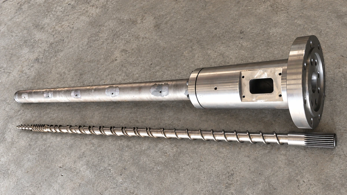
Why Your Single Screw Extruder Design Causes Extrusion Defects
Nov 13, 2026
Learn how single screw extruder design parameters—L/D ratio, compression ratio, channel depth, and mixing elements—affect melt quality, throughput, and defects.
Read Article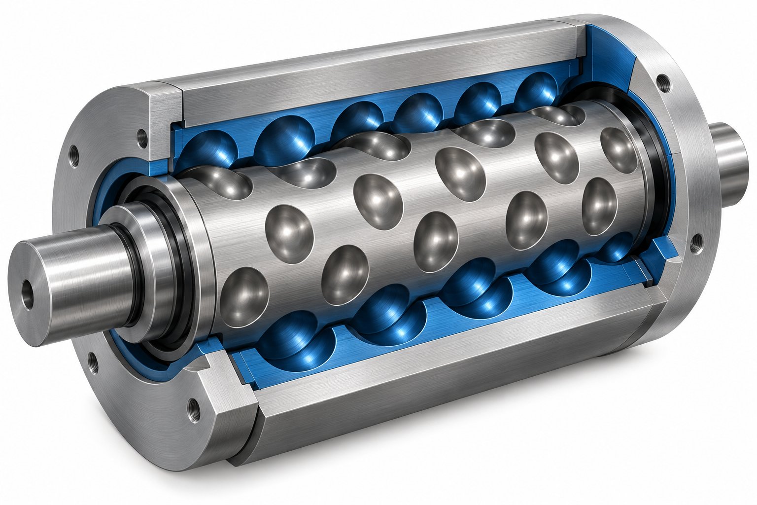
Cavity Transfer Mixer: The Blender Your Extruder Didn't Know It Needed
Nov 13, 2026
Learn how a cavity transfer mixer (CTM) upgrades single-screw extruder mixing. Covers working principles, key parameters, integration, applications, and comparisons.
Read Article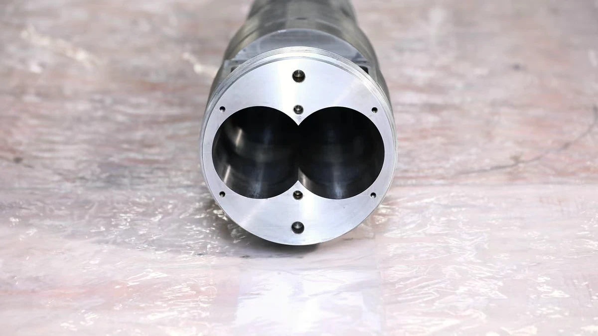
Extruder Barrel Alignment Decoded: Tolerances Most Plants Miss
Nov 13, 2026
Learn extruder barrel alignment tolerances, laser procedures, thermal offsets, and proactive schedules most plants miss — for single-screw and twin-screw lines.
Read ArticleLooking for something else?
Search by material, symptom or product and jump straight to the relevant page.
These are navigation suggestions based on keyword matching — not a quotation, not a delivery commitment, and not a substitute for engineering review. Final specification is confirmed by our engineers against your drawings and processed material.
Need help with screw barrel selection?
Share your machine model, processed material and application. Our team can help with pricing and technical support.