

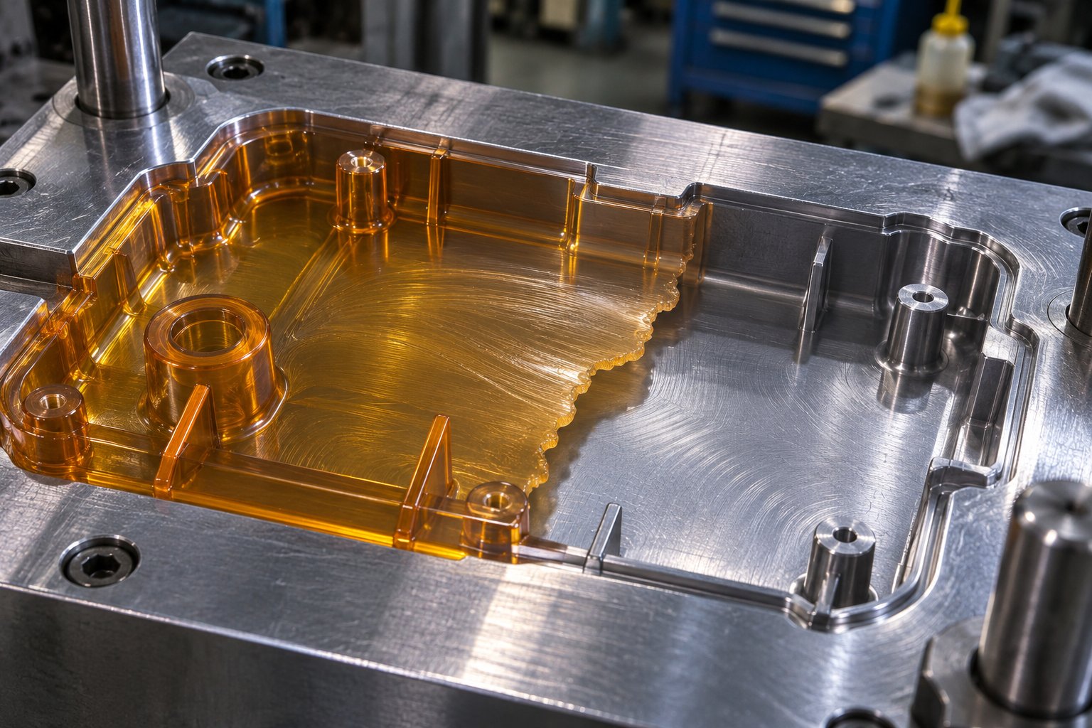
What Is a Short Shot in Injection Molding?
Imagine opening the mold after a cycle and finding a part with a missing corner, an unfilled rib, or a section that simply ends mid-feature. That incomplete part is the hallmark of one of the most frustrating defects in plastics processing: the short shot.
A short shot is an injection molding defect in which molten plastic fails to completely fill every region of the mold cavity, producing a part with missing sections, unfilled features, or visibly incomplete geometry.
Defining the Short Shot Defect
In practical terms, a short shot means the melt front stalled or froze before reaching the farthest extremities of the cavity. The result is unmistakable: gaps, thin edges, absent bosses, or blunt ends where material simply ran out of momentum. Any thermoplastic or thermoset resin can produce this defect, and it typically appears at the last-to-fill areas - the points farthest from the gate or near thin-walled features where flow resistance is highest. Unlike subtle cosmetic flaws, short shots render a part functionally useless. There is no reworking an incomplete part; it goes straight to the scrap bin.
Why Short Shots Demand Immediate Attention
A single short shot is a nuisance. Repeated short shots are a production crisis. Every incomplete part represents wasted resin, lost machine time, and a disrupted cycle schedule. When the defect goes undetected and incomplete parts reach downstream assembly, the consequences escalate - failed functional tests, customer complaints, and potential line shutdowns. Scrap rates climb, Overall Equipment Effectiveness drops, and technicians spend hours chasing a fix through trial-and-error adjustments.
It is equally important to distinguish a true short shot from underpacking. Both can produce parts that look incomplete or dimensionally off, but they originate at different stages of the cycle. Underpacking occurs when the cavity does fill during the injection phase, yet pack and hold pressure is insufficient to compensate for material shrinkage as the part cools. You'll notice sink marks, voids, or dimensional deviations rather than outright missing geometry. A short shot, by contrast, means the melt never reached certain regions of the cavity in the first place. Confusing the two leads to corrective actions aimed at the wrong phase of the process - a costly misdirection.
How This Guide Is Organized
Most troubleshooting resources hand you a bullet-point list of possible causes and leave you to guess which one applies. This guide takes a different approach. Every root cause of short shots is mapped through the 4M manufacturing framework - Machine, Mold, Material, and Method - a structured problem-solving model widely used in manufacturing root cause analysis. For each cause, you'll find the underlying physics that explain why it starves the flow front, the diagnostic indicator a technician would observe on the shop floor, and the specific corrective action to resolve it. Beyond root causes, the guide covers how part geometry and resin selection influence short shot risk before a mold ever opens, a step-by-step diagnostic protocol for isolating the true culprit, and a differential diagnosis table that separates short shots from visually similar defects like flash, sink marks, and burn marks.
The goal is straightforward: move you from reactive guessing to systematic root cause isolation - so the defect gets killed at its source, not chased from cycle to cycle.
Understanding the Fill Cycle and Where Short Shots Occur
Every injection molding cycle follows the same three-act structure: fill, pack/hold, and cooling. A short shot injection molding defect is born exclusively in the first act - the fill phase - when the melt front loses its race against the cold mold steel. To diagnose the problem effectively, you need to understand what that race looks like from the inside.
The Injection Fill Phase Explained
Picture molten plastic entering the cavity through the gate. From that instant, a clock starts ticking. The melt is hot - often between 200 and 300 degrees Celsius depending on the resin - but the mold steel is far cooler, typically held between 20 and 80 degrees Celsius. As the melt advances, it loses heat to the mold walls, and a frozen skin layer begins growing inward from the cavity surface. The open channel available for flow narrows with every millisecond.
This is the core dynamic behind every injection moulding short shot: the melt front must reach every corner, rib, boss, and end-of-flow region before the frozen layer chokes off the remaining flow channel. Injection pressure is the driving force pushing the melt forward, but viscous resistance fights back along the entire flow path. As the melt cools, its viscosity climbs sharply, demanding even more pressure to maintain movement. The relationship is straightforward - pressure must exceed the cumulative viscous resistance across the full flow length before solidification seals the channel shut.
Here is how the fill sequence unfolds inside the cavity:
- Gate entry. Molten plastic passes through the gate and enters the cavity at the set injection speed. The melt is at its hottest and most fluid.
- Flow-front advancement. The melt spreads outward from the gate, following the path of least resistance. A frozen skin layer forms against the cooler mold walls, progressively narrowing the effective flow channel.
- Pressure buildup along the flow path. As the front travels farther from the gate, the pressure required to keep it moving increases. Thinner walls, longer distances, and tighter features all amplify resistance.
- Last-to-fill regions. Areas farthest from the gate, thin ribs, and blind pockets are the last to receive material. These zones face the highest cumulative resistance and the coldest, most viscous melt.
- Completion or stall. If pressure and melt temperature remain sufficient, the cavity fills completely. If the frozen layer closes the channel or the machine runs out of available pressure, the front stops - and short shooting occurs.
How Flow-Front Freeze-Off Creates Incomplete Parts
Think of it as a narrowing pipe. The frozen skin growing inward from the mold walls acts like a constriction that tightens the longer the melt travels. At some point, the effective channel becomes so narrow that the remaining melt simply cannot push through, regardless of how much pressure the machine applies. This is freeze-off, and it is the direct physical mechanism behind most short shots.
Several factors accelerate freeze-off: low melt temperature means less thermal energy to resist cooling, low mold temperature pulls heat out of the melt faster, slow injection speed gives the frozen layer more time to grow, and thin wall sections offer less volume for the melt to flow through in the first place. Every one of these variables feeds back into the same pressure-flow-temperature equation.
Fill Phase vs Pack Phase Deficiency
Here is where many operators get tripped up. A true short shot occurs during the fill phase - the melt front never reaches all areas of the cavity. Gate freeze-off during the pack/hold phase is a different phenomenon. In that scenario, the cavity fills completely during injection, but the gate solidifies prematurely before adequate packing pressure can compensate for volumetric shrinkage. The resulting part may show sink marks, dimensional issues, or localized depressions near thick sections - but the geometry is nominally complete.
Both produce parts that look "not right," and they can even overlap when borderline fill conditions exist. The distinguishing question is simple: did the melt front reach the end of the flow path? If material is physically absent from a region of the part, you are dealing with a fill-phase deficiency. If the part shape is all there but surfaces are sunken or dimensions are undersized, the pack phase is the likely culprit.
This distinction matters because the corrective actions point in different directions. Chasing pack-phase parameters when the real issue is incomplete fill wastes time and can introduce new problems like flash or residual stress. The root causes explored in the next section are organized specifically to help you pinpoint which variables are starving the flow front during the fill phase - and which category of the 4M framework they belong to.

Root Causes of Short Shots Mapped Through the 4M Framework
Randomly tweaking injection speed, bump pressure up a notch, raise barrel temps, hope for the best - sound familiar? That trial-and-error loop burns hours and rarely lands on the actual problem. A structured approach changes the game entirely. The 4M framework - Machine, Mold, Material, and Method - gives technicians and engineers a disciplined way to walk through every variable that can starve the flow front, so the real culprit gets identified instead of buried under compensating adjustments.
Each category below breaks down the specific root cause, the process physics behind it, the diagnostic clue you would spot on the floor, and the corrective action that addresses the source rather than the symptom. A comprehensive reference table follows, consolidating every cause into a single asset you can print, laminate, and keep at the press.
Machine-Related Root Causes
The injection molding machine is the engine that drives melt into the cavity, and when that engine falls short, the part does too - literally. Four machine-side variables account for the majority of shortshot occurrences tied to hardware and settings:
Insufficient injection pressure. If the machine cannot generate enough hydraulic or servo-driven force to overcome the cumulative viscous resistance across the flow path, the melt front stalls before reaching the end of fill. You will notice the machine hitting its pressure limit during the fill phase - actual pressure flatlines at the set maximum while the screw still has travel remaining. The fix starts with verifying that the pressure limit is set high enough above the process demand to maintain velocity control throughout the fill. An undersized machine that simply lacks tonnage or injection capacity for the part geometry may require moving the mold to a larger press.
Inadequate shot size or cushion. When the shot size is set too low or the cushion disappears entirely, there is physically not enough melt in front of the screw to fill the cavity. Think of it as pouring from a pitcher that is only three-quarters full - the glass never tops off. A zero or near-zero cushion at the end of injection confirms the issue. Increasing the shot size and ensuring a consistent cushion of roughly 3 to 6 mm restores the material volume needed for a complete fill.
Low barrel temperature. Barrel zones set below the resin manufacturer's recommended range produce a melt that is cooler and more viscous than intended. That elevated viscosity demands more pressure to push the same distance, and the melt surrenders heat to the mold steel faster, accelerating freeze-off. If actual melt temperature measured with a pyrometer reads significantly below the setpoint, barrel heaters, thermocouples, or heater bands may need inspection or recalibration.
Slow injection speed. Speed and time are inseparable during fill. A sluggish injection speed gives the frozen skin layer more time to grow inward from the mold walls, narrowing the flow channel and choking the front before it reaches last-to-fill areas. Longer-than-expected fill times on the machine controller are the telltale sign. Increasing injection velocity - while monitoring for flash or burn marks - shortens the window available for freeze-off.
Mold-Related Root Causes
Even a perfectly tuned machine cannot compensate for a mold that resists flow. Mold-side issues are especially common in short run injection molding scenarios where tooling may receive less upfront simulation or where aging molds accumulate wear and contamination over many production cycles.
Poor or blocked venting. As the melt advances, it displaces air ahead of the flow front. If vents are crushed, clogged, or undersized, that trapped air compresses and creates back-pressure that the melt cannot overcome. The classic indicator is a shot short pattern that consistently appears at the same last-to-fill location, often accompanied by a glossy or slightly discolored mark where compressed gas resists the melt. Cleaning existing vents, adding vents at last-to-fill zones, or incorporating vacuum-assisted venting resolves the restriction.
Restricted or undersized gates. The gate is the bottleneck between the runner system and the cavity. If gate cross-sections are too small for the resin viscosity and part volume, the melt experiences excessive shear and pressure loss before it even enters the cavity. Shot shorts that appear across multiple cavities sharing the same gate design point squarely at this cause. Enlarging the gate orifice or changing the gate style - for example, switching from a submarine gate to a fan gate - reduces the restriction.
Unbalanced runner systems. In multi-cavity molds, runners that vary in length or diameter deliver unequal melt volumes to each cavity. Some cavities fill completely while others consistently come up short. The diagnostic is obvious: certain cavity positions produce incomplete parts every cycle, while neighboring cavities are fine. Balancing the runner layout - equalizing flow-path lengths and cross-sections - or using a hot-runner system with individual valve gates provides uniform delivery.
Insufficient mold temperature. A mold running too cold pulls heat from the melt aggressively, accelerating the growth of the frozen skin layer. Parts may fill on warmer days but produce intermittent shot shorts when ambient conditions cool or chiller setpoints drift. Monitoring actual mold surface temperature versus setpoint, and raising the mold temperature within the resin's recommended range, restores the thermal balance needed for complete fill.
Material and Method Root Causes
Hardware and tooling are only half the equation. The resin itself and the way the process is programmed introduce another layer of variables that can quietly starve the cavity.
High melt viscosity. Some resins are inherently thick and resist flow, especially glass-filled or mineral-filled compounds. If the material's Melt Flow Index is low relative to the cavity geometry, the melt may simply lack the fluidity to reach thin features or long flow paths. Consistently incomplete parts across all cavities, even with pressure and speed maximized, suggest the material is fighting the geometry. Switching to a higher-flow grade or adjusting melt temperature upward within the resin's safe window reduces resistance.
Moisture-induced viscosity spikes. Hygroscopic resins like nylon, polycarbonate, and PET absorb atmospheric moisture. During injection, that trapped moisture flashes to steam, creating gas pockets and spiking effective viscosity. Parts may exhibit splay marks alongside incomplete fill, and defects often worsen over the course of a production run as improperly dried material works through the hopper. Verifying dryer performance, dew-point readings, and residence time in the dryer corrects the issue at its source.
Contamination and degraded regrind. Foreign material or over-processed regrind alters melt behavior unpredictably. Contamination can partially block gates or nozzles, while degraded regrind raises viscosity and introduces inconsistency shot to shot. Visual inspection of purge shots for discoloration, black specks, or unmelted particles reveals contamination. Controlling regrind ratios, inspecting incoming material, and purging the barrel before production starts eliminate these variables.
Premature velocity-to-pressure transfer. The switchover point - where the machine transitions from velocity-controlled fill to pressure-controlled pack - is one of the most critical method parameters. If switchover happens too early, the machine drops to pack pressure before the cavity is adequately filled, and the remaining volume never receives enough driving force. A fill-only part test, made by disabling second-stage pressure, reveals whether the cavity reaches approximately 95 to 99 percent full on velocity alone. Adjusting the switchover position or using cavity-pressure-based transfer ensures the transition happens at the right moment.
Incorrect process settings. Broader method errors - wrong cycle parameters carried over from a different mold, setup sheets that do not match current material lots, or manual overrides left in place from a previous troubleshooting session - create conditions ripe for incomplete fill. Comparing live machine settings against the validated process setup document catches discrepancies quickly. Establishing and enforcing standardized setup procedures prevents these avoidable shot shorts from recurring.
The table below consolidates every root cause into a single diagnostic reference. Use it as a systematic checklist: work through each category, match the diagnostic indicator to what you observe on the press, and apply the corresponding corrective action.
| Category | Root Cause | Why It Causes a Short Shot | Diagnostic Indicator | Corrective Action |
|---|---|---|---|---|
| Machine | Insufficient injection pressure | Melt front cannot overcome viscous resistance across the full flow path | Machine reaches pressure limit during fill; screw travel stops prematurely | Increase pressure limit; verify machine size is adequate for part geometry |
| Machine | Inadequate shot size / zero cushion | Not enough melt volume in front of the screw to fill the cavity | Cushion position at zero or near-zero at end of injection | Increase shot size; maintain 3-6 mm cushion consistently |
| Machine | Low barrel temperature | Cooler melt has higher viscosity; loses heat to mold faster, accelerating freeze-off | Actual melt temperature reads below setpoint; heater fault alarms | Raise barrel temps to resin spec; inspect heater bands and thermocouples |
| Machine | Slow injection speed | Longer fill time allows frozen skin layer to grow, narrowing the flow channel | Fill time exceeds validated range; short appears at thin or distant features | Increase injection velocity incrementally; monitor for flash or burns |
| Mold | Poor or blocked venting | Trapped air compresses ahead of flow front, creating back-pressure the melt cannot overcome | Short consistently at same last-to-fill location; possible gas burn marks | Clean vents; add vents at last-to-fill zones; consider vacuum venting |
| Mold | Restricted or undersized gates | Excessive pressure drop at gate starves the cavity of driving force | Short shots across cavities sharing same gate design; high gate-region shear | Enlarge gate orifice; change gate style to reduce restriction |
| Mold | Unbalanced runner system | Unequal flow-path lengths deliver different melt volumes to each cavity | Specific cavity positions consistently short while others fill completely | Balance runner lengths and diameters; consider hot-runner valve gates |
| Mold | Insufficient mold temperature | Cold mold extracts heat rapidly, accelerating frozen-layer growth and premature freeze-off | Intermittent shorts correlating with ambient temperature drops or chiller drift | Raise mold temperature within resin-recommended range; verify coolant flow |
| Material | High melt viscosity | Thick melt resists flow, especially through thin walls and long paths | Parts incomplete even at maximum pressure and speed across all cavities | Switch to higher-flow grade; raise melt temperature within safe window |
| Material | Moisture-induced viscosity spike | Moisture flashes to steam, creating gas pockets and raising effective viscosity | Splay marks alongside incomplete fill; defect worsens as undried material feeds through | Verify dryer dew point, temperature, and residence time; re-dry material |
| Material | Contamination / degraded regrind | Foreign material blocks flow paths; degraded regrind raises viscosity unpredictably | Black specks, discoloration, or unmelted particles in purge shots | Control regrind ratio; inspect incoming material; purge barrel before production |
| Method | Premature velocity-to-pressure transfer | Machine drops to lower pack pressure before cavity is adequately filled | Fill-only part test shows cavity well below 95% full on velocity alone | Adjust switchover position later; use cavity-pressure-based transfer |
| Method | Incorrect process settings | Wrong parameters from prior mold, material lot, or troubleshooting overrides starve fill | Live settings do not match validated setup sheet; unexplained shift in part quality | Audit settings against setup document; enforce standardized setup procedures |
One critical takeaway from this framework: real-world shot shorts are rarely single-cause events. A mold with borderline venting can run fine until a slightly higher-viscosity material lot arrives, or a gradually wearing check ring slowly reduces effective shot volume until it crosses the threshold. The 4M categories are not isolated silos - they interact. A marginal condition in one category compounds a marginal condition in another, producing intermittent defects that seem random but are actually the predictable result of stacked tolerances. Mapping every variable systematically is what separates a permanent fix from a temporary band-aid.
Of course, many of these root causes trace back to decisions made long before the machine ever cycles - decisions about wall thickness, gate location, and cavity geometry that determine how forgiving or punishing the flow path will be.
Part Geometry and Short Shot Plastic Injection Molding Risk
A technician can optimize every machine parameter on the press and still fight short shots injection molding defects cycle after cycle - because the real problem was locked into the part design months earlier, before a single pellet was melted. Wall thickness, flow-path length, feature geometry, and gate location collectively define how much resistance the melt front will face. Get these wrong, and you are building a short shot into the steel itself.
How Thin Walls and Complex Geometry Starve the Flow Front
Wall-thickness uniformity is the single most influential geometry variable in preventing incomplete fill. When the melt encounters an abrupt transition from a thick section to a thin one, something called the hesitation effect takes over. The melt preferentially flows through the thicker, lower-resistance path while the thinner section stalls. That stalled front loses heat rapidly, viscosity spikes, and the frozen layer seals the thin section shut - even though plenty of material and pressure may exist elsewhere in the cavity. The result is a localized short shoot that no amount of pressure adjustment at the press can reliably fix.
Imagine pouring water through a funnel that suddenly narrows to a pinhole halfway down. The flow chokes at the restriction regardless of how fast you pour. Melt behaves similarly. Abrupt thickness changes should be tapered over at least three times the nominal wall thickness rather than stepped, giving the melt a gradual transition instead of a sudden bottleneck.
Every resin has a maximum flow-length-to-wall-thickness ratio - the farthest distance the melt can travel through a given wall thickness before it freezes off. Unfilled polypropylene can reach ratios around 250:1, while polycarbonate drops to roughly 100:1. A 300 mm polycarbonate part with a 1.2 mm wall and a single gate will not fill, no matter how hard the machine pushes. Either the wall needs to be thicker, a second gate needs to be added, or the resin needs to change. Ignoring this ratio is one of the fastest paths to chronic short shots.
Beyond walls, specific features act as flow restrictors that amplify the risk:
- Thin ribs. If the rib base drops below roughly 40% of the nominal wall, fill becomes unreliable. Ribs taller than three times their thickness are especially prone to short shoots at their tips because the melt must travel a long, narrow channel that cools rapidly.
- Bosses fused into sidewalls. Merging a boss directly into a wall creates an oversized thick section in one spot and a flow-starved zone around it. Standing the boss off and connecting it with gussets distributes flow more evenly.
- Living hinges. These ultra-thin flex zones - often just 0.25 to 0.50 mm thick - present extreme resistance to melt flow. Placement relative to the gate is critical; locating a living hinge at the end of a long flow path is a near-guarantee of incomplete fill.
Gate Placement and Runner Balancing Strategies
Gate location dictates where the melt enters the cavity and, by extension, how far it must travel to reach every feature. The guiding principle is straightforward: gate into the thickest section and let material flow from thick to thin. Gating into a thin section forces the melt through a high-resistance zone first, burning pressure before it reaches the larger volume downstream. The thick region then packs poorly, and distant thin features risk short shots.
Minimizing the total flow-path length directly reduces the pressure required for complete fill. For parts with long aspect ratios or complex branching geometry, a single gate may not be enough. Adding a second gate - or repositioning the primary gate to a more central location - can cut the maximum flow distance in half, dramatically lowering the odds of freeze-off at extremities.
Multi-cavity molds introduce another layer of complexity. Unbalanced runner systems deliver different melt volumes to each cavity, causing some positions to fill completely while others consistently produce short shot plastic injection molding defects. A geometrically balanced runner layout - where every cavity sees the same runner length and cross-section from the sprue - ensures uniform fill. Family molds, where different part geometries share the same tool, are especially prone to imbalance and may require runner resizing or individual valve gates to equalize flow rates.
Vent placement deserves equal attention. Vents belong at last-to-fill locations - the points where the melt front arrives last and trapped air has nowhere to escape. If those locations are not vented, the compressed air pocket pushes back against the flow front and prevents complete fill. Short-shot studies during mold sampling reveal exactly where those last-to-fill zones land, and vents should be cut there before production begins.
Using Mold-Flow Simulation to Predict Short Fill Risk
Every geometry risk discussed above - hesitation, excessive flow-path ratios, unbalanced runners, and inadequate venting - can be predicted before the mold is machined. Mold-flow simulation software models the fill phase digitally, showing exactly how the melt front advances, where air traps form, where hesitation stalls the front, and whether the cavity fills completely at the intended process conditions. Automatic checks flag short shots, weld lines, sink marks, and air traps, often within minutes of setting up the analysis.
For multi-cavity molds, simulation tools include runner-balancing wizards that iterate gate and runner dimensions automatically until equal fill rates are achieved across all cavities. This eliminates the expensive trial-and-error of cutting steel first and adjusting later.
Running a fill simulation is not a luxury reserved for high-volume automotive programs. Even a quick first-pass analysis on a single-cavity part can expose a wall that is too thin for the flow distance, a gate that is in the wrong spot, or a rib that will never fill. Catching those issues in CAD costs an afternoon. Catching them after the tool is hardened costs weeks of rework and production delay.
Before steel is cut, designers and mold engineers should evaluate the following DFM checklist of geometry-related short shot risk factors:
- Nominal wall thickness held within plus or minus 10% across the entire part, with all transitions tapered over at least 3x the wall thickness
- Flow-length-to-wall-thickness ratio checked against the selected resin's published limit
- Rib base thickness between 40% and 60% of the nominal wall; rib height no greater than 3x rib thickness
- Bosses cored from the base and connected with gussets rather than fused directly into sidewalls
- Living hinges and ultra-thin features positioned close to the gate rather than at end-of-fill
- Gate located in the thickest section, with flow directed from thick to thin
- Maximum flow-path length minimized; second gate considered if the path exceeds the resin's capability
- Runner system geometrically balanced for all cavities in multi-cavity molds
- Vents placed at every identified last-to-fill zone and behind features that could trap air
- Mold-flow simulation completed and reviewed for incomplete fill, hesitation, and air-trap warnings
Every item on this list is a design-phase decision. Addressing each one before tooling is committed eliminates the most common geometric causes of short shots - and spares the production team from fighting a defect that no machine parameter can fully compensate for. Yet even with ideal geometry, the resin flowing through that cavity introduces its own set of variables. Different polymer families behave in fundamentally different ways under shear and heat, and those material-level differences can tip a borderline fill into an incomplete one.
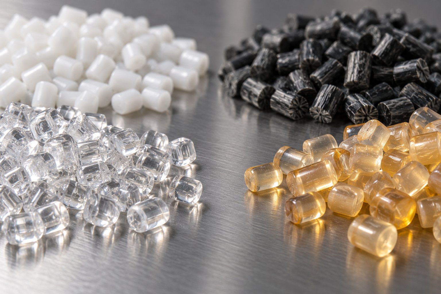
Material Science Behind Short Shots in Injection Molding
Two molds running on adjacent presses, identical machine settings, same operator - yet one fills perfectly while the other keeps shooting short. The difference? The resin. Polypropylene sits in one hopper; 30% glass-filled nylon sits in the other. That single variable - what the plastic actually is and how it behaves under heat and shear - can mean the difference between a complete part and scrap.
Most troubleshooting guides treat "high viscosity" as a single line item and move on. In reality, every resin family brings its own viscosity profile, thermal sensitivity, moisture behavior, and flow personality to the equation. Understanding those differences is what separates a technician who fixes a short shot in injection molding from one who chases it for an entire shift.
Viscosity and Shear-Thinning Behavior Across Resins
Viscosity - the melt's resistance to flow - is the central material property governing whether a cavity fills or falls short. But here is the nuance most operators miss: viscosity is not a fixed number. It changes with temperature, it changes with shear rate, and those changes vary dramatically from one polymer to the next.
Most polymer melts are shear-thinning fluids, meaning they become less viscous when forced to flow faster. Increase the injection speed, and the effective viscosity drops - sometimes significantly. This is why bumping injection velocity can resolve a borderline fill without raising temperature or pressure. The melt literally becomes thinner as it moves faster through the gate and runner.
The degree of shear-thinning, however, differs by resin family. Polypropylene and polyethylene are strongly shear-thinning: push them faster and their viscosity drops sharply, making them relatively forgiving in complex geometries. Polycarbonate and PMMA are less responsive to shear rate changes, so you cannot rely on speed alone to compensate for a difficult flow path.
Thermal sensitivity adds another dimension. Semi-crystalline resins - nylon (PA6, PA66), polypropylene (PP), polyethylene (PE), and PBT - have a distinct melting point rather than a gradual softening range. Below that melting point, the material is essentially solid. Above it, viscosity drops rapidly. This creates a narrow processing window: a few degrees too low and the melt is stiff, reluctant, and prone to stalling in thin features. A few degrees too high and thermal degradation begins. When you are running nylon at a barrel temperature just barely above its melt point, you are already flirting with incomplete fill on every cycle.
Amorphous resins - polycarbonate (PC), ABS, polystyrene (PS), and PMMA - behave differently. They do not have a sharp melt transition. Instead, they soften gradually over a broad thermal range, giving you a wider window to adjust melt temperature without crossing a critical threshold. That broader window generally makes amorphous materials more forgiving for short shot prevention, though their absolute viscosity can still be high (polycarbonate, for example, is inherently thick even at elevated temperatures).
Then come the filled compounds. Adding glass fibers, mineral fillers, or carbon fibers to any base resin increases its effective viscosity because solid particles disrupt the flow and add internal friction. Glass-filled nylon, one of the most common engineering compounds, demands injection pressures between 75 and 100 MPa - substantially higher than the unfilled grade. A 30% glass fill can increase the required injection pressure by 30 to 50 percent compared to the neat resin. The higher the filler loading, the worse the flow. A 50% glass-filled nylon is significantly more resistant than a 30% grade, and parts with long flow paths or thin walls become exponentially harder to fill.
Moisture, Contamination, and Degradation Effects
Even the right resin at the right temperature can produce a short shot if it carries hidden moisture. Hygroscopic resins - nylon, polycarbonate, PET, PBT, and certain TPU grades - absorb water from ambient air. That moisture does not simply evaporate harmlessly during processing. At barrel temperatures, trapped water molecules cause hydrolytic degradation: they break polymer chains, reduce molecular weight, and paradoxically can spike effective viscosity by generating gas pockets and disrupting flow. Steam bubbles expanding inside the melt create voids, splay marks, and localized pressure losses that starve the flow front of driving force.
The effect is insidious because it worsens gradually. A hopper of nylon that was properly dried four hours ago may have reabsorbed enough atmospheric moisture to cross the threshold where short shots begin appearing. Nylon grades typically need to be dried to below 0.2% moisture content by weight. Polycarbonate requires below 0.02%. Miss those targets, and you are essentially injecting a different material than what the process was validated for.
Best practices for drying go beyond simply running a dryer. You'll want to verify the dew point of the desiccant dryer (it should read -40 degrees Celsius or lower for most engineering resins), confirm that residence time in the dryer matches the resin manufacturer's recommendation, and ensure that material throughput does not exceed the dryer's capacity. Over-drying creates its own problems - prolonged exposure to heat can degrade certain resins, causing discoloration and property loss - so following the material data sheet is essential.
Contamination introduces unpredictability that no process setting can compensate for. Foreign resin from a previous production run, metal flakes from equipment wear, or dust from poor housekeeping can partially block nozzles, gates, or hot-runner channels. Even a small restriction at the gate creates a disproportionate pressure drop that robs the cavity of fill energy.
Degraded regrind is a subtler culprit. Every time plastic is reprocessed, the polymer chains shorten slightly and the material's flow behavior shifts. Regrind that has been through multiple heat histories can have measurably higher viscosity than virgin resin of the same grade. Mixing high percentages of degraded regrind with virgin material creates shot-to-shot viscosity variation - some shots flow easily while others resist fill, producing intermittent short shots that appear random but trace directly to inconsistent melt homogeneity. Controlling the regrind ratio (typically capping it at 20 to 25 percent of the total shot weight) and ensuring the regrind has not been over-processed keeps this variable in check.
Lot-to-lot viscosity variation in virgin resin is another factor worth monitoring. Two bags of the same grade from the same supplier can differ in Melt Flow Index by 10 to 15 percent. For a process running near the edge of its fill window, that shift alone can push a borderline fill into an incomplete one. Tracking incoming MFI values and adjusting process parameters proactively when a new lot arrives prevents the surprise.
Resin-Specific Processing Considerations
The table below compares the most commonly molded resin families, highlighting the viscosity behavior, moisture sensitivity, and short shot risk factors specific to each. Use it as a quick reference when setting up a new material or troubleshooting an incomplete fill on an unfamiliar resin.
| Resin Type | Viscosity Behavior | Moisture Sensitivity | Short Shot Risk Factors | Key Processing Considerations |
|---|---|---|---|---|
| Polypropylene (PP) | Low viscosity; strongly shear-thinning; flows easily at moderate temperatures | Non-hygroscopic; drying generally not required | Long flow paths in thin-wall packaging; high flow-length-to-thickness ratios | Wide processing window; fast injection speeds effective; monitor for warpage rather than fill issues |
| Polyethylene (PE - HDPE/LDPE) | Low to moderate viscosity; good shear-thinning response | Non-hygroscopic | Very thin walls in blow-molded conversions; thick-to-thin transitions | Broad thermal range; easy to fill most geometries; watch for sink rather than short shots |
| ABS | Moderate viscosity; amorphous with gradual softening; decent shear-thinning | Mildly hygroscopic; dry 2-4 hours at 80°C | Complex cosmetic parts with thin ribs or snap features at end of fill | Broad processing window; melt temps 220-260°C; responsive to speed adjustments |
| Polycarbonate (PC) | High viscosity; amorphous but inherently thick; limited shear-thinning benefit | Hygroscopic; must dry to below 0.02% moisture; 3-4 hours at 120°C | High viscosity limits flow-length ratios; thin-wall sections freeze quickly; moisture causes splay and viscosity spikes | Requires high melt temps (280-320°C) and high injection pressure; strict drying discipline essential |
| Nylon (PA6, PA66) | Low viscosity when properly melted; semi-crystalline with a sharp melt point; narrow window | Highly hygroscopic; dry to below 0.2%; 4-6 hours at 80°C | Narrow processing window; moisture-induced degradation spikes viscosity and creates gas; rapid crystallization causes fast freeze-off | Process close to melt point; use hot molds (60-90°C); verify drying dew point rigorously |
| Glass-Filled Nylon (PA + GF) | High effective viscosity due to fiber content; fibers disrupt flow and increase pressure demand by 30-50% | Highly hygroscopic; same drying as unfilled nylon | Filler loading increases pressure demand significantly; thin ribs and long flow paths become high-risk; fiber orientation affects mechanical properties | Injection pressures 75-100 MPa; use hot molds (100-120°C); avoid low cylinder temps that shorten fiber length |
| PET | Moderate viscosity; semi-crystalline with sharp melt point; crystallizes rapidly at certain temps | Highly hygroscopic; dry to below 0.005%; 4-6 hours at 150-170°C | Extremely moisture-sensitive; undried PET degrades and loses IV rapidly; narrow melt range | Strict drying is non-negotiable; minimize residence time in barrel; use dehumidifying dryers only |
| PBT | Moderate viscosity; semi-crystalline; rapid crystallization rate | Hygroscopic; dry 2-4 hours at 120°C | Fast crystallization narrows fill window; thin features freeze rapidly | Fast injection speeds essential; mold temps 60-80°C; gate freeze-off risk in small gates |
| Polystyrene (PS) | Low to moderate viscosity; amorphous; flows easily | Non-hygroscopic | Low risk for standard geometries; extreme thin-wall applications may require attention | Very wide processing window; one of the easiest resins to fill; forgiving on most parameters |
A few patterns emerge from this comparison. Semi-crystalline resins with sharp melt transitions and high moisture sensitivity - nylon and PET especially - cluster the most short shot risk factors into a single material. Amorphous, non-hygroscopic resins like polypropylene and polystyrene sit at the opposite end, offering wide processing windows and forgiving flow behavior. Filled compounds land in their own high-risk category regardless of the base resin, simply because the solid particles disrupt flow and multiply pressure requirements.
The practical takeaway is this: material selection and preparation are not peripheral to short shot prevention - they are foundational. Choosing a higher-viscosity resin without accounting for geometry limitations, or skipping drying steps on a hygroscopic grade, bakes the defect into the process before the first cycle ever starts. Matching the resin's flow characteristics to the part geometry, maintaining disciplined drying protocols, controlling regrind quality, and tracking lot-to-lot MFI variation keep the material variable inside the boundaries where the process can deliver a complete fill every shot.
Knowing the material is only half the battle, though. When short shots still appear despite correct resin handling and validated settings, you need a structured way to work through the evidence on the shop floor - reading the part, reading the data, and narrowing down which variable actually crossed the line.
Systematic Troubleshooting Methodology for Injection Molding Short Shots
A 4M root cause table on the wall is valuable. A resin comparison chart in the binder helps. But when you are standing at the press staring at an incomplete part, what you actually need is a sequence - a logical path that tells you what to check first, what to check next, and how each answer narrows the field. Guessing wastes cycles. A structured protocol does not.
The diagnostic method below treats each injection molding short shot as a piece of evidence. Where the defect appears, how consistently it appears, and what the machine data says during the event all point toward specific categories of root cause. Follow the steps in order. Each one either confirms a suspect or eliminates it, moving you closer to the actual source instead of the most convenient assumption.
Reading the Part to Identify the Failure Zone
Before touching a single machine parameter, pick up the part and study it. The location of the incomplete fill is your first and most revealing clue.
Short shots concentrated at last-to-fill areas - the points farthest from the gate, at the tips of ribs, at the ends of runners in multi-cavity tools - suggest the melt ran out of driving force before reaching the extremities. Venting problems, insufficient injection pressure, low melt temperature, or slow fill speed are all strong suspects when the defect consistently lands at the end of the flow path.
Short shots appearing at random or shifting locations tell a different story. If the incomplete region moves from one area to another shot to shot, or if different cavities short on different cycles, the issue is less likely to be mold geometry and more likely tied to material or machine inconsistency - a leaking check ring, fluctuating barrel temperature, inconsistent material feed, or variable melt viscosity from moisture or contamination.
Short shots isolated at specific thin-walled features while the rest of the part fills normally point toward a localized geometry restriction. A thin rib, a narrow boss, or a section with an abrupt thickness transition is choking off flow in that zone. This pattern often means the mold or part design needs attention rather than the process settings.
Step-by-Step Root Cause Isolation Protocol
With the visual evidence in hand, work through the following diagnostic sequence. Each step builds on the previous answer, progressively narrowing the root cause.
- Inspect the defect location on five to ten consecutive short parts. Determine whether the incomplete fill appears at the same last-to-fill zone every cycle (consistent pattern) or shifts randomly between locations or cavities (inconsistent pattern). Record which regions are affected and photograph representative samples.
- Weigh five to ten consecutive shots. Use a precision scale and record each shot weight individually - not just the average. Calculate the range (heaviest minus lightest) and the percent variation. High shot-weight variability (greater than 0.5% variation) points toward the machine: a worn or inconsistent check ring, erratic screw recovery, or feed-throat inconsistencies. Consistently low shot weight with tight repeatability points toward process settings (shot size too small, early transfer) or mold restrictions (blocked vent, undersized gate).
- Perform a fill-only test. Disable second-stage (pack/hold) pressure entirely and run several shots on velocity alone. The resulting short shot should fill approximately 95 to 99 percent of the cavity. If the fill-only part is significantly less than 95 percent full, the melt is not getting enough volume or pressure during the velocity phase - check shot size, injection speed, barrel temperature, and switchover position. If it fills to roughly 95 percent, the velocity phase is adequate and the issue may lie in the transition to pack or in a localized flow restriction.
- Compare actual process data to setpoints. Pull injection pressure curves, fill time, and cushion position from the machine controller. Does actual injection pressure hit the machine's maximum limit during fill? That signals insufficient available pressure. Is actual fill time longer than the validated window? That confirms a speed or viscosity problem. Does cushion disappear to zero at transfer? The barrel does not contain enough melt. Each data point either confirms or eliminates a suspect from the 4M table.
- Check melt temperature with a pyrometer. Purge a small amount of melt into free air and measure its temperature immediately. If actual melt temperature is more than 10 degrees Celsius below the target, barrel heaters, thermocouples, or screw geometry may be underperforming. Low melt temperature elevates viscosity and accelerates freeze-off - a direct path to incomplete fill.
- Inspect the mold vents and gate condition. Pull the mold or examine the parting line surfaces at last-to-fill areas. Vents packed with residue, flattened by over-clamping, or never cut in the first place are a leading cause of persistent shorts at consistent locations. Gate orifices worn oversized or partially blocked by cold slugs also alter fill balance.
- Evaluate material condition. Confirm the dryer is operating at the correct temperature and dew point for the resin. Check the regrind ratio and visually inspect pellets for contamination, discoloration, or moisture clumping. Run a moisture analysis if the resin is hygroscopic. Material-related viscosity spikes are one of the most common causes of intermittent defects, particularly in short run plastic injection molding environments where dryer setups may change frequently between different materials.
- Run a dynamic check-ring repeatability test. Perform ten consecutive identical cycles and record shot weight for each. If weight varies by more than 0.5 percent, the non-return valve is suspect. A worn check ring allows melt to flow backward during injection, reducing the effective volume delivered to the cavity and producing erratic fill from shot to shot.
When Multiple Causes Compound
Here is the reality that separates textbook troubleshooting from shop-floor problem-solving: short shots in production are rarely the result of a single variable crossing a hard threshold. More often, two or three marginal conditions stack on top of each other until the combined effect pushes the process over the edge.
Consider a scenario you might encounter on any given Tuesday. The mold vents are partially fouled - not completely blocked, but restricted enough to add a few bar of back-pressure at the last-to-fill zone. The material is nylon that was dried correctly four hours ago but has been sitting in an open hopper, slowly reabsorbing moisture. Individually, neither condition is severe enough to cause a defect. Together, the slightly elevated melt viscosity from marginal moisture meets the slightly elevated cavity pressure from restricted venting, and the flow front stalls two millimeters short of a complete fill. The defect appears intermittent and random because ambient humidity, dryer cycling, and mold temperature fluctuations all influence whether the stacked margins land just inside or just outside the fill window on any given shot.
This compounding effect explains why adjusting a single parameter sometimes "fixes" the short shot temporarily without addressing the actual root cause. Bumping injection pressure by 5 percent might push the melt past the restriction today, but when the material lot changes next week and viscosity shifts by a few percent, the defect returns. A permanent fix requires identifying and correcting every marginal contributor, not just the one that happens to be the most obvious.
The diagnostic protocol above is designed to expose these compound scenarios. By checking shot weight consistency, process data, melt condition, and mold condition independently, you build a complete picture of which variables are marginal rather than zeroing in on a single suspect and stopping the investigation. Document every finding, even the ones that seem borderline, because borderline is exactly where compounding failures live.
Of course, accurate diagnosis also depends on correctly identifying the defect in the first place. Short shots share visual similarities with several other injection molding problems - and misidentifying a sink mark, a void, or a burn mark as an incomplete fill sends the entire troubleshooting effort down the wrong path.
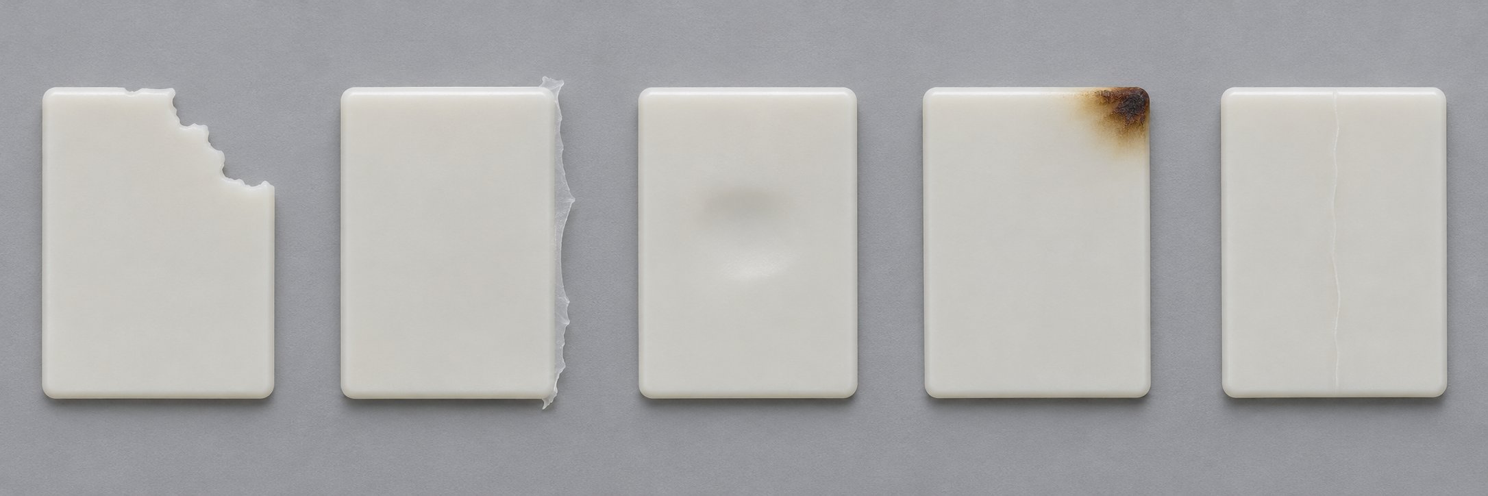
Differential Diagnosis: Short Shot Defect vs Visually Similar Injection Molding Problems
Misidentifying a defect is worse than not diagnosing it at all. When an operator calls a sink mark a short shot, the corrective actions that follow - raising injection speed, increasing shot size, opening vents - target the wrong phase of the process entirely. The result is wasted time, potentially new defects introduced by unnecessary adjustments, and an original problem that persists untouched. A short shot defect in injection molding has distinct characteristics that separate it from every other common molding flaw, but those distinctions are easy to miss under production pressure when a part simply looks "not right."
Short Shots vs Flash and Overfill Defects
Flash and incomplete fill injection molding defects sit at opposite ends of the same spectrum. A short shot means the melt did not reach every region of the cavity. Flash means the melt went beyond the cavity, seeping through parting lines, across shut-off surfaces, or around ejector pins to form thin fins of excess material. One defect reflects too little pressure, volume, or flow capability. The other reflects too much - or tooling that can no longer contain what the machine delivers.
The visual distinction is straightforward: a short shot leaves material missing from the part, while flash adds material where it should not exist. Where confusion creeps in is when operators try to fix a short shot by pushing the process harder - more pressure, faster speed, higher melt temperature - and inadvertently tip into flash at the parting line. That sequence, as covered in the venting discussion by JeekMould, often signals that a mold-side restriction like poor venting is the real problem. The machine is being forced to overpower a vent deficiency, and the excess force finds the weakest seal in the tool. If increasing pressure simultaneously resolves the short shot and introduces flash, the root cause is almost certainly venting or flow restriction - not raw machine capacity.
Understanding the short shot vs flash injection molding relationship helps you avoid this seesaw. The goal is never to brute-force the cavity full; it is to remove the restriction that prevented clean filling in the first place.
Distinguishing Sink Marks, Voids, and Burn Marks
Sink marks are the defect most commonly confused with short shots by less experienced operators. Both produce parts that look incomplete or deficient. The critical difference? A sink mark appears on a part that actually filled. The mold cavity received enough melt to form the complete geometry, but inadequate packing pressure or insufficient cooling time allowed the interior to shrink and pull the surface inward, leaving a shallow depression. You will see dimples or depressions - typically over thick sections, near ribs, or around bosses - but the part outline is fully formed. With a short shot, material is physically absent. There are no depressions because there is no surface to depress. The part geometry simply ends where the melt front stopped.
The process variable that separates them is equally clear. Sink marks respond to pack and hold phase adjustments - higher packing pressure, longer hold time, and improved cooling. Short shots respond to fill phase adjustments - injection speed, melt temperature, shot volume, and venting.
Voids are the hidden cousins of both defects. A part with internal voids appears complete on the outside - every feature is present, every edge is formed - but cutting the part open reveals trapped air pockets or vacuum cavities within the wall. Voids typically form in thick cross-sections where the outer skin solidifies first, then the interior shrinks away from itself without enough packing to compensate. The part passes visual inspection but fails structural or leak testing. If you suspect voids, cross-sectioning or X-ray inspection confirms the diagnosis. A short shot, by contrast, never hides. The missing material is visible on the surface without any destructive testing.
Burn marks deserve special attention because they frequently co-occur with short shots when poor mold venting is the root cause. Trapped gas at a last-to-fill location compresses, heats rapidly, and scorches the resin - leaving a darkened, discolored patch at the exact point where the melt front stalled. You might see an incomplete feature with a charred edge, or a part that alternates between short shots and burn marks depending on minor cycle-to-cycle variation. This short shot burn marks mold venting connection is one of the most reliable diagnostic clues available: if the same location shows both incomplete fill and discoloration across a sample of parts, venting is almost certainly the primary culprit. Improving vent depth and placement at that location resolves both symptoms simultaneously because both originate from the same trapped gas.
Weld lines (knit lines) round out the comparison. These visible seams appear where two melt fronts converge from different directions - around a core pin, through multiple gates, or after splitting to flow around an obstruction. The fronts meet and bond, but the junction is visible as a faint line and can be structurally weaker than the surrounding material. The key distinction is that no material is missing. The part is fully formed; you are simply seeing the boundary where two flow fronts joined. Weld lines respond to melt temperature and injection speed increases that improve bonding at the junction. Short shots respond to entirely different variables because the problem is not bonding - it is that the melt never arrived.
Quick-Reference Defect Comparison Table
The table below consolidates every comparison into a single diagnostic reference. When you pick up a suspect part, match the visual evidence to the correct row and follow the corrective direction that corresponds to the actual defect - not the one it resembles at a glance.
| Defect | Visual Appearance | Key Distinguishing Feature | Common Root Cause Overlap with Short Shots | Primary Corrective Direction |
|---|---|---|---|---|
| Short Shot | Material physically absent from one or more regions of the part; features are incomplete, edges are blunt, or sections end abruptly | Geometry is missing - not deformed, not marked, but absent entirely | N/A (baseline defect) | Fill phase: increase injection speed, pressure, melt temp, shot size; improve venting; widen gates; correct switchover point |
| Flash | Thin fins or excess material protruding along parting lines, ejector pins, or shut-off surfaces | Material extends beyond the intended part boundary rather than falling short of it | Both can stem from venting issues - poor vents cause shorts; pushing process harder to compensate causes flash elsewhere | Reduce injection pressure or speed; inspect parting line fit and clamp tonnage; fix venting to eliminate the need for excessive process force |
| Sink Marks | Shallow depressions or dimples on the surface, typically over thick sections, ribs, or bosses | Part geometry is fully formed; defect is a surface depression, not missing material | Both can result from insufficient material delivery, but sinks are a pack-phase shortage while shorts are a fill-phase shortage | Pack/hold phase: increase packing pressure, extend hold time, improve cooling uniformity; redesign thick sections |
| Voids | Part appears complete externally; internal air pockets or vacuum cavities revealed only by cross-section, X-ray, or functional failure | No surface evidence of missing material; defect is entirely internal | Both relate to insufficient material delivery, but voids form after the skin solidifies while the interior shrinks; shorts are visible on the outside | Increase packing pressure and hold time; core out thick sections; reduce wall thickness variation; improve cooling |
| Burn Marks | Dark, charred, or yellowish discoloration at last-to-fill areas or near trapped-gas locations | Discoloration or scorching is present; material may be present but degraded, rather than absent | High overlap - both frequently caused by inadequate venting at last-to-fill zones; can appear on the same part simultaneously | Improve venting at last-to-fill zones; reduce injection speed to lower gas compression; clean residue from vent channels |
| Weld / Knit Lines | Visible seam or line where two melt fronts converged; no material is missing from the part | Part is fully formed; defect is a bonding weakness at the flow-front junction, not an absence of material | Minimal overlap - weld lines indicate flow fronts met, while short shots indicate a flow front never arrived | Increase melt temperature and injection speed to improve bonding; relocate gates to move weld line; improve venting near junction |
A practical habit worth building: before launching into any corrective action, ask one binary question. Is material physically missing from the part, or is the part fully formed but flawed? If material is absent, you are in the fill phase and the 4M root-cause framework applies directly. If the part shape is complete but shows depressions, internal cavities, discoloration, or seam lines, the corrective path diverges sharply toward packing, cooling, venting gas management, or flow-front bonding. Getting that first answer right saves every minute that follows.
Accurate defect identification steers you toward the right category of corrective action - but one category that often gets overlooked sits inside the machine itself. Wear on the plasticizing hardware can quietly erode fill performance over thousands of cycles, creating conditions that mimic process or mold problems while the real issue hides behind the barrel shroud.
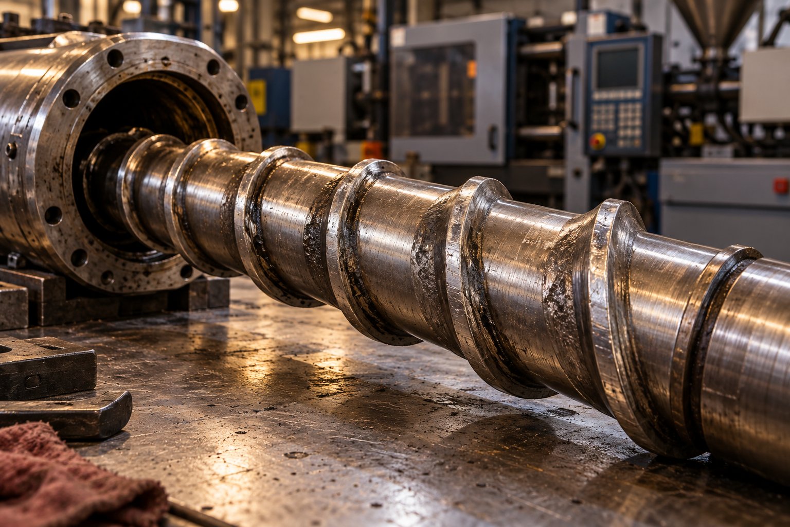
Plasticizing Hardware Condition and Injection Molding Screw Barrel Wear
You have confirmed the process settings match the validated setup sheet. The resin is properly dried. The mold vents are clean. Yet shot weight drifts unpredictably from cycle to cycle, and incomplete parts keep landing on the conveyor. Where do you look next? Behind the barrel shroud - at the plasticizing components that quietly degrade over thousands of hours of operation, eroding fill performance so gradually that no single shift notices the change until the process falls off a cliff.
Injection molding screw barrel wear is one of the most underdiagnosed contributors to short shots because its effects mimic other root causes. A worn check ring looks like a process inconsistency. A degraded barrel bore looks like a temperature problem. A mismatched screw geometry looks like a resin issue. Unless you inspect the hardware directly, you can chase the wrong suspect indefinitely.
Check-Ring Wear and Shot Volume Loss
The check ring - also called a non-return valve - sits at the front end of the screw and serves one critical function during injection: it seals the melt in front of the screw so that forward screw travel pushes material into the cavity rather than allowing it to leak backward through the flights. When the check ring wears, that seal degrades. Melt flows backward during the injection stroke, and the effective volume delivered to the cavity drops.
Imagine squeezing a syringe with a leaking plunger. You push the same distance every stroke, but the amount of fluid that exits the tip varies depending on how much slips past the worn seal. That is exactly what happens with a worn check ring. The machine controller reports the same screw travel and the same transfer position every cycle, but the actual mass of plastic entering the cavity fluctuates unpredictably. Some shots fill. Others fall short. The defect appears intermittent and random - the hallmark of check ring wear short shot problems.
A shot-mass repeatability study is the definitive diagnostic tool here. Disable pack and hold pressure entirely, run ten consecutive fill-only shots, weigh each one individually, and calculate the percent variation. For all-electric machines, variation above 0.5% suggests the non-return valve components need attention. For servo-hydraulic units, the threshold sits around 0.8%, and older hydraulic presses may tolerate up to 1.5% before the valve is considered suspect. Variation well beyond those benchmarks - say, 3% or more - strongly indicates a worn tip, ring, or seat assembly that needs replacement.
One important caution: machine settings themselves can influence check-ring repeatability and create false positives. Excessive melt decompression (suck-back) after screw recovery, for example, can draw air into the barrel through the nozzle-sprue interface, producing shot-weight variation that looks like a leaking valve but is actually a process parameter issue. Research from Orbital Plastics Consulting demonstrated that increasing decompression from 0.2 inch to 0.5 inch on an all-electric press caused shot-weight variation to spike from under 0.4% to nearly 4.5% - not because the valve was worn, but because air was entering the barrel. Before condemning a check ring, verify that decompression amounts are minimal (typically 0.1 to 0.3 inch) and that the nozzle-to-sprue-bushing seal is tight.
Screw Geometry Mismatch and Melt Quality
Even a brand-new check ring cannot compensate for a screw that does not match the resin it is processing. The screw's compression ratio, L/D ratio, and metering-section depth determine how effectively it melts, mixes, and pressurizes the polymer. Run the wrong screw for the material, and you get poor melt homogeneity - pockets of unmelted pellets mixed with overheated material, inconsistent viscosity from shot to shot, and inadequate pressure development to push the melt through the full flow path.
A common scenario: a general-purpose screw designed for polyethylene gets pressed into service running glass-filled nylon. The compression ratio is too low to generate the shear heat that nylon demands, and the metering depth is too deep to build adequate pressure for the high-viscosity compound. The result is a melt that arrives at the nozzle partially unmelted, thermally inconsistent, and unable to fill the cavity reliably. Operators compensate by cranking barrel temperatures higher, which fixes the symptom temporarily but introduces thermal degradation, longer cycle times, and increased energy costs.
Barrel and screw wear compounds the geometry problem over time. As Glycon Corp.'s Jeff Kuhman explains, the original clearance between the screw flight OD and the barrel bore is typically just 0.001 inch per side per inch of diameter - an extremely tight tolerance designed to maximize shear-heat input and pressure-generating capacity. As those clearances increase through abrasive or adhesive wear, three things happen simultaneously. First, the screw loses its ability to generate pressure efficiently because melt leaks backward over the worn flights. Second, shear-heat input drops because the wider gap reduces the mechanical work done on the polymer. Third, the melt arriving at the front of the barrel is cooler and more viscous than it should be - a direct setup for freeze-off and incomplete fill.
Abrasive wear accelerates dramatically when processing filled resins. Glass fibers, mineral fillers, and flame retardants act like sandpaper against flight lands and barrel linings. A screw running unfilled polypropylene might last years before clearances become problematic. The same screw running 30% glass-filled nylon can reach unacceptable wear levels in a fraction of that time, with some aggressive filler packages reducing useful life by 50% or more. The wear is often concentrated at the transition zone and metering section, exactly where pressure generation and melt homogeneity matter most.
Material retention in worn barrels introduces yet another layer of risk. Dead spots - areas where melt stagnates in eroded pockets or widened clearances - allow resin to degrade thermally over extended residence time. That degraded material periodically breaks loose and enters the melt stream as contamination, altering viscosity and disrupting flow behavior unpredictably. If purge shots reveal dark specks, discolored streaks, or charred fragments despite clean virgin material in the hopper, barrel-wall dead spots are a likely source.
When to Replace or Upgrade Plasticizing Components
Knowing that the plasticizing unit degrades is only useful if you act on it before the degradation becomes a production crisis. Reactive replacement - waiting for the screw to fail catastrophically or for scrap rates to become intolerable - means unplanned downtime, emergency procurement lead times, and days of lost production. A proactive approach schedules inspections and replacements around measured wear data, not crisis events.
The following hardware inspection checkpoints should be part of every plasticizing unit maintenance short shots prevention program:
- Check-ring sealing test: Run ten fill-only shots at validated settings and weigh each individually. Calculate percent variation. Variation exceeding acceptable thresholds for the machine type (0.5% for all-electric, 0.8% for servo-hydraulic, 1.5% for older hydraulic) indicates the tip, ring, or seat requires inspection and likely replacement.
- Screw flight measurement: Pull the screw during a scheduled maintenance window and measure flight OD at multiple points along its length using a micrometer. Compare to the original specification. Significant diameter reduction in the transition or metering zones confirms abrasive wear that is reducing pressure capacity and shear-heat input.
- Barrel bore measurement: Use an inside bore gauge to measure the barrel ID at several positions along its length. Increased diameter beyond the original tolerance - especially in the transition and metering zones - confirms barrel-side wear. Cross-reference with screw measurements to determine whether wear is screw-side, barrel-side, or both.
- Melt-quality evaluation: Purge the barrel at processing temperature and examine the extrudate for unmelted pellets, discoloration, streaks, gas bubbles, or charred particles. Poor melt quality despite correct temperature settings and adequate back pressure points to screw geometry limitations, excessive clearance, or barrel dead spots.
When measurements confirm that replacement is necessary, resist the temptation to simply reorder OEM-equivalent parts. The original screw geometry may never have been ideal for the resins and parts you are running today - especially if the application has evolved since the machine was purchased. A replacement screw and barrel specified to match the actual application - accounting for the specific resin family, filler content, shot size requirements, and mixing demands - delivers better melting performance, tighter shot-weight repeatability, and a wider process window than a generic drop-in replacement.
This is where working with a specialist manufacturer adds tangible value. NANHAIYA's custom injection molding screw barrels, for example, are manufactured around the specific machine specifications, resin characteristics, and shot requirements of each application. Their technical review process evaluates screw geometry, wear patterns, melting performance, mixing needs, and material-retention concerns before recommending a design - ensuring the replacement addresses the root cause of the wear rather than simply duplicating the component that failed. For maintenance teams planning a plasticizing-unit rebuild or upgrade, that application-matched approach translates directly into more consistent shot delivery, better melt quality, and fewer of the fill deficiencies that produce short shots cycle after cycle.
Screw and barrel condition is the hardware foundation that everything else in the injection process rests on. When that foundation erodes, even perfectly optimized settings and well-designed molds cannot compensate for the melt-quality and shot-volume inconsistencies that worn components introduce. Treating plasticizing hardware maintenance as a preventive discipline - rather than a reactive emergency - eliminates one of the most persistent and least visible contributors to incomplete fill. That same preventive mindset, applied systematically across every phase of the molding operation, is what ultimately separates shops that occasionally fight short shots from shops that rarely see them at all.
How to Prevent Short Shots in Injection Molding: Strategy and Economics
Fixing a short shot after it appears on the conveyor is recovery. Preventing it from ever occurring is engineering. Every section of this guide so far has traced the defect backward - from symptom to root cause, from root cause to contributing variable. This final section reverses the direction entirely, looking forward across the product lifecycle to show where prevention delivers the highest return and why the economics justify investing in it aggressively.
The Hidden Cost of Short Shots in Production
Most shops quantify short shot costs by weighing the scrap bin. That number, while real, dramatically understates the actual damage. Resin waste is often the smallest line item in the true cost structure. The larger losses hide in places that rarely make it onto a cost report.
Consider what actually happens when short shots start appearing mid-run. The press keeps cycling while the operator notices the defect, meaning several incomplete parts may reach the packing station before anyone reacts. Production stops for troubleshooting - sometimes for minutes, sometimes for an entire shift if the root cause is elusive. A technician begins adjusting parameters, running test shots, and inspecting results, consuming machine time that was scheduled for salable parts. Meanwhile, downstream operations - assembly, packaging, shipping - sit idle or scramble to rearrange schedules around the shortfall. If the defect escaped initial inspection and reached a customer, the consequences escalate to returns, complaints, and potential qualification audits.
Each of these disruptions erodes Overall Equipment Effectiveness (OEE) across all three of its components simultaneously. Availability drops because the press is down for troubleshooting. Performance drops because test shots and slow startups reduce effective cycle output. Quality drops because every incomplete part is scrap. A single short shot event that takes two hours to resolve on a press running a 30-second cycle represents 240 lost shots - and the OEE hit ripples through the shift report, the weekly capacity plan, and the monthly cost variance.
The most valuable step any molder can take is to quantify these losses using their own production data. Pull the downtime logs, scrap records, and rework labor hours associated with short shot events over the past quarter. Add the material cost of scrapped parts, the machine-hour cost of lost production time, and any expedited shipping charges incurred to meet delivery commitments after an unplanned stoppage. That total - almost always far higher than the scrap-bin estimate alone - becomes the business case for investing in prevention rather than continuing to pay for reaction.
A Tiered Prevention Strategy
Short shot prevention strategies do not live in a single department or a single phase of the product lifecycle. They span design, commissioning, and ongoing production - with each tier building on the one before it. Miss a tier, and the downstream phases inherit risk that no amount of shop-floor heroics can fully eliminate.
- Design-phase prevention. This is where the highest-leverage decisions are made and where short shot elimination starts. Conduct a thorough DFM review that evaluates wall-thickness uniformity, flow-length-to-wall-thickness ratios, rib and boss proportions, and gate placement relative to last-to-fill zones. Run mold-flow simulation to predict fill behavior, air traps, hesitation zones, and required injection pressure before committing to steel. Optimize vent placement at every identified last-to-fill location. Balance runners geometrically in multi-cavity tools. Every risk factor caught in CAD costs a fraction of what it costs to correct after the mold is built.
- Commissioning-phase prevention. Once the mold is on the press, scientific molding principles and Design of Experiments (DOE) replace trial-and-error setup. Characterize the resin's viscosity curve through an in-mold rheology study. Establish the fill-only target using a short shot progression. Set the velocity-to-pressure transfer point based on cavity pressure or screw position data, not operator intuition. Use DOE to evaluate how melt temperature, injection speed, mold temperature, and packing pressure interact, then define a validated process window - the range of parameter combinations that consistently produce complete, dimensionally acceptable parts. Document every validated setting on a standardized setup sheet that travels with the mold.
- Production-phase prevention. A validated process window only protects you if you monitor adherence to it and maintain the equipment that supports it. Implement statistical process monitoring on key variables - shot weight, cushion position, peak injection pressure, and fill time - so that drift toward the edge of the window triggers an alert before the defect appears. Schedule preventive maintenance for plasticizing components (check-ring sealing tests, screw and barrel measurements) and mold components (vent cleaning, gate inspection, runner condition) at intervals driven by shot count and material abrasiveness, not calendar dates alone. Enforce material handling discipline: verify dryer dew points before every production start, cap regrind ratios, and track incoming resin lot-to-lot MFI variation so that viscosity shifts are anticipated rather than discovered through scrap.
Each tier addresses a different time horizon and a different set of 4M variables, but they reinforce each other. A well-simulated mold design reduces the sensitivity of the process to marginal machine or material conditions. A scientifically validated process window means the production team knows exactly which parameters to monitor and what constitutes a deviation. Disciplined maintenance and material handling ensure that the hardware and resin conditions stay within the boundaries the validated window assumes.
Building a Short-Shot-Resistant Process
Short shot prevention is a system-level outcome rooted in the 4M framework: Machine capability maintained through scheduled hardware inspections, Mold performance protected by simulation-driven design and regular vent and gate maintenance, Material behavior controlled through disciplined drying and incoming quality checks, and Method stability ensured by scientific molding setup and real-time process monitoring. No single adjustment eliminates the defect permanently - only the coordinated management of all four categories does.
That philosophy separates shops that treat short shots as isolated fire drills from those that rarely encounter the defect at all. Reactive troubleshooting will always have a place - unexpected conditions arise, molds age, materials change. But when the prevention infrastructure is in place, those events become exceptions rather than recurring crises. The injection molding scrap reduction short shots deliver is measurable: lower material waste, fewer unplanned stoppages, tighter OEE numbers, and shipments that leave on schedule instead of waiting for a technician to finish chasing a fill deficiency.
The path from chronic short shots to a resilient, short-shot-resistant process is not a single corrective action. It is a commitment to systematic thinking - diagnosing with the 4M framework, validating with data, preventing through design and discipline, and maintaining the hardware foundation that makes consistent fill possible. Every section of this guide has equipped you with a specific tool for a specific phase of that journey. The rest is execution.
Frequently Asked Questions About Injection Molding Short Shots
1. What is the difference between a short shot and underpacking in injection molding?
A short shot occurs during the fill phase when molten plastic physically fails to reach all regions of the mold cavity, leaving sections of the part entirely missing. Underpacking, on the other hand, happens after the cavity has filled during the pack/hold phase - the melt reaches every area, but insufficient packing pressure causes the material to shrink, producing sink marks, dimensional deviations, or internal voids rather than absent geometry. The corrective actions differ significantly: short shots require fill-phase adjustments such as increasing injection speed, pressure, or melt temperature, while underpacking responds to higher packing pressure, longer hold time, and improved cooling. Confusing the two leads technicians to adjust the wrong phase of the process, wasting time and potentially introducing new defects.
2. What are the most common causes of short shots in injection molding?
Short shots stem from four categories organized under the 4M manufacturing framework. Machine-related causes include insufficient injection pressure, inadequate shot size or zero cushion, low barrel temperature, and slow injection speed. Mold-related causes involve poor or blocked venting, undersized gates, unbalanced runner systems, and low mold temperature. Material causes encompass high melt viscosity, moisture-induced viscosity spikes in hygroscopic resins like nylon and polycarbonate, and contamination from degraded regrind. Method causes include premature velocity-to-pressure transfer and incorrect process settings carried over from previous jobs. In practice, short shots on the production floor are rarely single-cause events - marginal conditions in two or three categories often compound to push the process past the fill threshold.
3. How do you troubleshoot a short shot on the production floor?
Start by inspecting the defect location on five to ten consecutive parts to determine whether the incomplete fill appears consistently at the same last-to-fill zone or shifts randomly. Weigh consecutive shots individually - high shot-weight variation (above 0.5%) points to machine issues like a worn check ring, while consistently low weight with tight repeatability suggests process settings or mold restrictions. Perform a fill-only test by disabling pack/hold pressure; the part should reach approximately 95-99% full on velocity alone. Compare actual process data (injection pressure, fill time, cushion position) against validated setpoints, check melt temperature with a pyrometer, inspect mold vents and gate condition, evaluate material drying and contamination status, and run a check-ring repeatability test. Each step either confirms or eliminates a suspect from the 4M root-cause categories.
4. Can part design cause short shots even with optimized machine settings?
Absolutely. Wall-thickness uniformity, flow-length-to-wall-thickness ratios, and feature geometry collectively determine how much resistance the melt front encounters. Abrupt thickness transitions trigger a hesitation effect where the melt stalls in thinner sections and freezes before filling them. Thin ribs with bases below 40% of the nominal wall, bosses fused directly into sidewalls, and living hinges positioned far from the gate all act as flow restrictors. Every resin has a maximum flow-length-to-wall-thickness ratio - for example, polycarbonate tops out around 100:1, so a 300 mm PC part with 1.2 mm walls and a single gate simply will not fill regardless of process optimization. Running mold-flow simulation before cutting steel catches these issues when they cost an afternoon to fix rather than weeks of rework.
5. How does screw and barrel wear contribute to short shots?
A worn check ring (non-return valve) allows melt to leak backward during the injection stroke, reducing the effective shot volume delivered to the cavity. This creates unpredictable shot-weight variation where some cycles fill and others fall short. Barrel and screw wear increases the clearance between the screw flight OD and barrel bore, reducing both pressure-generating capacity and shear-heat input. The melt arrives cooler and more viscous than intended, accelerating freeze-off. Abrasive resins like glass-filled nylon accelerate this wear dramatically. Suppliers such as NANHAIYA manufacture custom injection molding screw barrels tailored to specific machine specifications, resin characteristics, and shot requirements, helping maintenance teams address root-cause wear rather than simply duplicating the component that failed.
Written by
Nanhaiya Technical Team
Zhoushan Nanhaiya Plastic Machinery Co., Ltd.
The Nanhaiya technical team supports screw and barrel manufacturing projects through application review, technical communication, custom manufacturing coordination, and production and quality control.
Discuss Your Application
Related Articles
More insights on screw barrel technology and plastics processing.
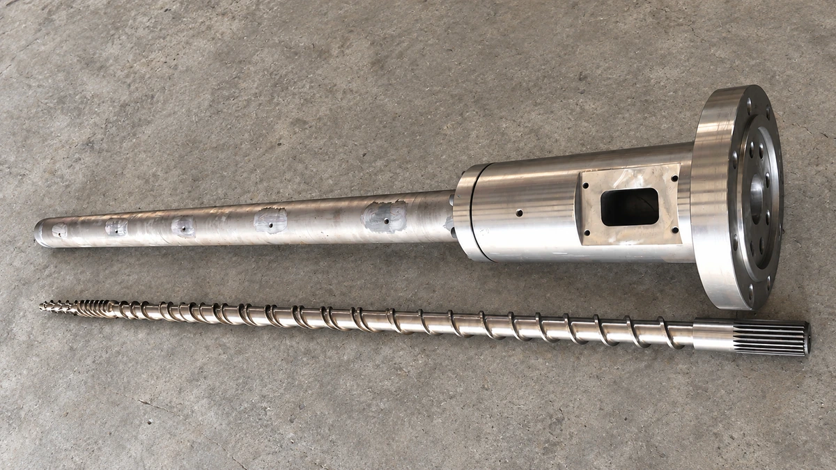
Why Your Single Screw Extruder Design Causes Extrusion Defects
Nov 13, 2026
Learn how single screw extruder design parameters—L/D ratio, compression ratio, channel depth, and mixing elements—affect melt quality, throughput, and defects.
Read Article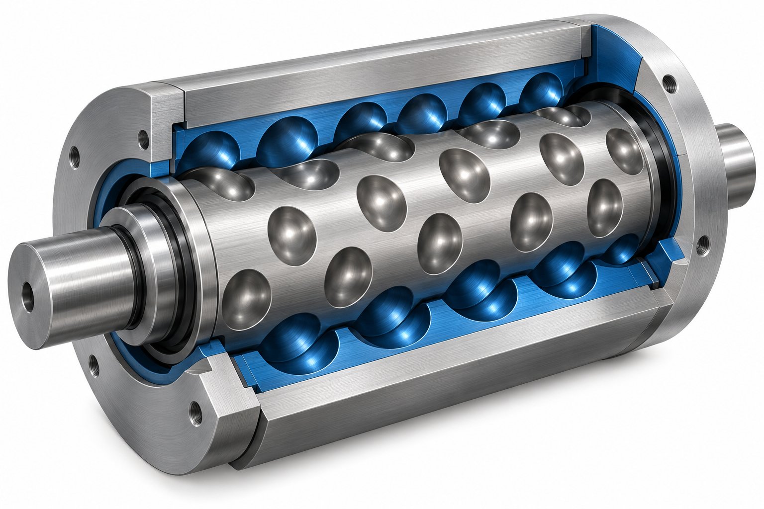
Cavity Transfer Mixer: The Blender Your Extruder Didn't Know It Needed
Nov 13, 2026
Learn how a cavity transfer mixer (CTM) upgrades single-screw extruder mixing. Covers working principles, key parameters, integration, applications, and comparisons.
Read Article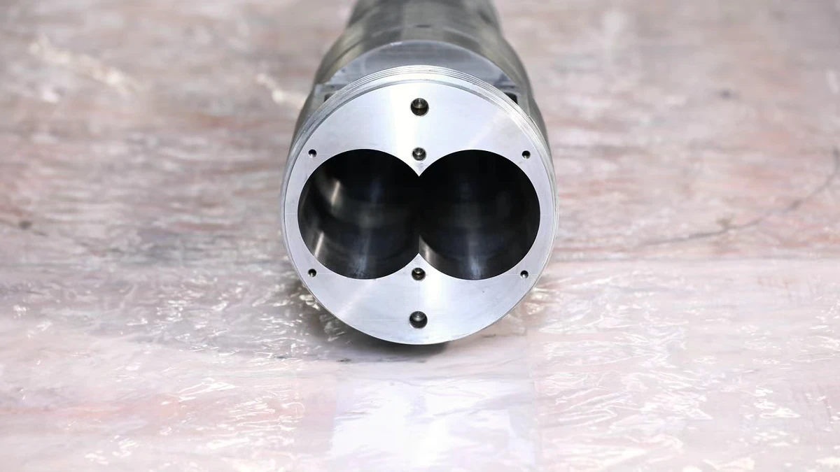
Extruder Barrel Alignment Decoded: Tolerances Most Plants Miss
Nov 13, 2026
Learn extruder barrel alignment tolerances, laser procedures, thermal offsets, and proactive schedules most plants miss — for single-screw and twin-screw lines.
Read ArticleLooking for something else?
Search by material, symptom or product and jump straight to the relevant page.
These are navigation suggestions based on keyword matching — not a quotation, not a delivery commitment, and not a substitute for engineering review. Final specification is confirmed by our engineers against your drawings and processed material.
Need help with screw barrel selection?
Share your machine model, processed material and application. Our team can help with pricing and technical support.