

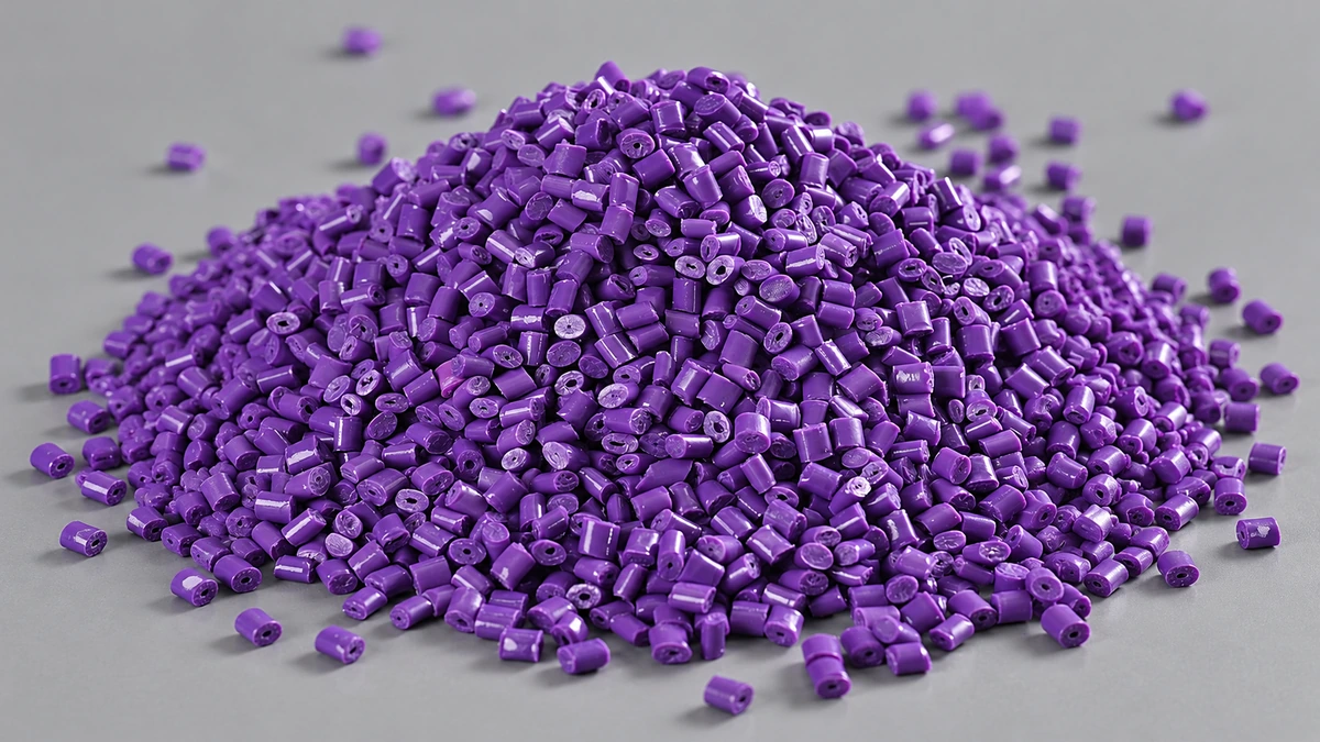
What Masterbatch Dispersion Really Means for Polymer Processors
Imagine pulling a finished plastic part off the line only to find dark specks, faint color streaks, or a dull haze where there should be a glossy surface. The formula looks right on paper. The pigment is the correct grade. Yet something went wrong between pellet and part. More often than not, the culprit is poor masterbatch dispersion.
Defining Masterbatch Dispersion in Practical Terms
Masterbatch dispersion is the process by which concentrated pigment or additive agglomerates held within a carrier resin are broken down and uniformly distributed throughout a host polymer matrix during melt processing, converting clustered raw colorant into individually separated, spatially homogeneous particles that deliver consistent color, opacity, and mechanical performance.
That definition captures the full masterbatch meaning as it applies to real-world compounding and molding. Whether you are coloring a polypropylene masterbatch for automotive trim or tinting polyethylene film for packaging, the underlying challenge is identical: pigments never arrive as the perfectly separated particles a datasheet implies. They come as tightly bound clusters that must be torn apart and spread evenly through millions of polymer chains. The quality of that breakup-and-spread sequence is what separates a flawless part from a reject bin.
Why Dispersion Quality Determines Part Performance
Dispersion quality is not one variable among many — it is the variable. Incomplete breakup of pigment agglomerates triggers surface specks, reduced color strength, and localized weak points that compromise impact resistance. Poor spatial distribution causes streaking, color drift between shots, and inconsistent opacity. As processors from New York (NY) to Guangzhou have learned, even premium pigments underperform when the dispersion process falls short. The economic cost compounds quickly: higher scrap rates, tighter rework cycles, and customer complaints that erode margins.
How This Resource Is Organized
This guide is built around the scientifically recognized three-stage dispersion model — wetting, deagglomeration, and distribution — a framework that clarifies every downstream decision. Each section maps directly onto that model: pigment chemistry and why different colorants resist breakup in different ways, carrier resin selection and let-down ratio science, twin-screw extruder configuration strategies, dispersion aids compared without brand bias, a full defect diagnosis taxonomy, and practical quality measurement methods that close the feedback loop. The goal is to give you a single, technically grounded resource that connects cause to effect at every stage.
The logical starting point is the dispersion process itself — what physically happens inside a melt when agglomerates begin to break apart, and why that sequence unfolds in three distinct phases rather than one.
The Three Stages of Pigment Dispersion Explained
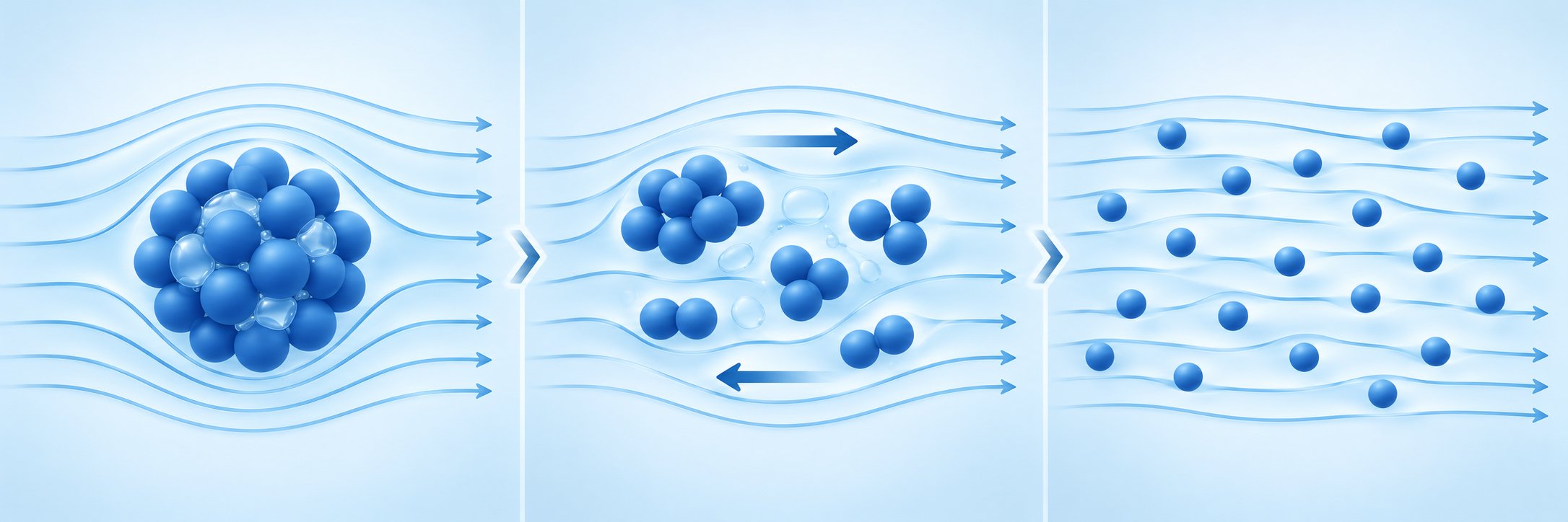
Every master batch that enters a melt-processing line carries the same hidden problem: pigment particles are not individual specks sitting neatly inside the carrier resin. They are dense clusters — agglomerates — held together by surface forces and riddled with trapped air. Converting those clusters into a uniform coloring system requires three distinct physical events, each governed by its own mechanism and each capable of failing independently. Understanding this three-stage sequence is what turns a reactive troubleshooter into someone who can design dispersion quality into a process from the start.
Stage One — Wetting and Air Displacement
Before any mechanical breakup can begin, the polymer melt must penetrate the fine capillaries between pigment particles inside each agglomerate and push out the trapped air and adsorbed moisture. This is wetting — the replacement of a gas-solid interface with a liquid-solid one. You'll notice the process depends heavily on the surface energy differential between pigment and resin: when the melt's surface tension is lower than the pigment's surface energy, the liquid spontaneously wicks into the cluster. When that gap is narrow or reversed, wetting stalls and dry cores survive deep into the mixing zone, no matter how much shear energy follows.
In practice, pigments with high specific surface area — carbon black grades used in masterbatch production, for example — present enormous total void volume. More void volume means more air to displace and a longer wetting window. If the wetting stage is incomplete, subsequent shear simply fractures the outer shell of the agglomerate while the interior remains dry and intact, seeding the specks and gels that show up in finished parts.
Stage Two — Deagglomeration Through Shear
Once the melt has wetted the agglomerate surfaces, mechanical forces take over. Deagglomeration — also called dispersive mixing — is the stage where external shear stress applied by the melt must exceed the cohesive forces binding primary particles together. Think of it as a tug-of-war: on one side, van der Waals attraction and mechanical interlocking hold the cluster intact; on the other, hydrodynamic drag and compressive forces from the processing equipment work to pull it apart.
The cohesive strength of an agglomerate is not a single fixed number. It scales with primary particle size, specific surface area, and what the carbon black industry calls "structure" — quantified by DBP (dibutyl phthalate) oil absorption. High-structure carbon blacks have open, branched aggregates with large internal void volume, making them easier to distribute but harder to wet initially. Organic pigments such as phthalocyanine blue present extremely small primary particles and correspondingly high cohesive energy, demanding intense shear to fracture. The masterbatch manufacturing process must deliver enough stress — in the right zone, for enough residence time — to overcome these forces and reduce clusters toward their primary particle size.
Stage Three — Distributive Homogenization
Breaking agglomerates apart is necessary but not sufficient. Imagine a melt where every cluster has been shattered into fine particles, yet those particles all sit in the same narrow region of the flow channel. The result would be color-rich streaks next to pigment-starved zones. Distributive mixing solves this problem through spatial randomization: repeated splitting, reorientation, and recombination of melt streams spread the already-deagglomerated particles across the entire polymer matrix.
Unlike stage two, distribution does not require high shear stress. It relies on geometric complexity — elements that divide and recombine the flow many times over — rather than brute force. The goal is to eliminate concentration gradients so that any small sample taken from the melt contains the same pigment loading as every other. Sounds straightforward, but if the distributive stage is too short or poorly designed, color inconsistency between parts or even within a single part is inevitable.
| Stage | Mechanism | Key Variables |
|---|---|---|
| 1 — Wetting | Polymer melt displaces air and moisture from agglomerate voids, establishing liquid-solid contact | Surface energy differential between pigment and resin, pigment specific surface area, melt viscosity, void volume of agglomerate |
| 2 — Deagglomeration (Dispersive Mixing) | Hydrodynamic shear stress exceeds cohesive forces binding primary particles, fracturing agglomerates into finer units | Applied shear stress, particle size and surface area, agglomerate structure (e.g., DBP absorption), residence time in high-shear zone |
| 3 — Distribution (Distributive Mixing) | Repeated stream splitting, folding, and reorientation spatially randomize deagglomerated particles throughout the matrix | Number of stream divisions, mixing element geometry, total mixing length, melt flow uniformity |
These three stages overlap in real equipment — wetting continues as fresh agglomerate surfaces are exposed by shear, and some distribution happens even in high-stress zones. Still, treating them as a sequence clarifies a critical diagnostic principle: every dispersion defect traces back to a failure in a specific stage. Specks point to incomplete deagglomeration. Streaks point to poor distribution. Gels and fish eyes often trace all the way back to failed wetting. That cause-and-effect clarity becomes especially powerful when you recognize that dispersive and distributive mixing, despite sounding similar, rely on fundamentally different physics — and demand different hardware solutions.
Dispersive Versus Distributive Mixing and Why Both Matter
The terms "dispersive" and "distributive" show up constantly in technical datasheets, screw design guides, and troubleshooting reports for plastic masterbatch processing. Yet they are routinely swapped, blurred, or treated as synonyms. That confusion is not just academic — it leads engineers to install the wrong mixing elements, chase the wrong root cause, and waste hours of machine time on problems that a clearer vocabulary would solve in minutes. Pulling these two concepts apart is essential for anyone working with masterbatches at any stage of the manufacturing process.
Dispersive Mixing and Agglomerate Breakup
Dispersive mixing is all about force. Its sole purpose is to fracture agglomerates into smaller fragments — ideally down to their primary particle or aggregate size. The mechanism hinges on a simple condition: the externally applied stress must exceed the cohesive forces holding particles together inside a cluster. In a twin-screw extruder, that stress is generated primarily in narrow-gap, high-energy zones — think wide kneading discs plowing through a fully filled channel, or the tight tip clearance between screw flight and barrel wall where both shear and elongational flow fields intensify.
Wide kneading discs, as compounding specialists note, form a pool of molten polymer in front of each disc as it rotates, smearing the material under high shear. That plowing action is exactly what cohesive pigments like phthalocyanine blue or high-structure carbon black need to break apart. Without enough dispersive energy, agglomerates survive intact and show up as specks or undispersed grit in the final part — no amount of stirring downstream will fix a particle that was never broken.
Distributive Mixing and Spatial Uniformity
Distributive mixing operates on a completely different principle. Instead of applying brute force, it rearranges already-broken-down particles so that every micro-region of the melt carries the same pigment concentration. The mechanism relies on repeated stream splitting, reorientation, and recombination — essentially slicing the melt into thin layers and restacking them over and over until concentration gradients vanish.
In hardware terms, this calls for narrow kneading discs, gear-type mixing elements, or toothed blocks that slice through the polymer in a scissoring action rather than smearing it. Shear stress is moderate, even gentle. The priority is geometric complexity: the more times the melt stream is divided and recombined, the more uniform the particle distribution becomes. This is especially critical for masterbatch types where delicate additives — glass fibers, metallic flakes, or shear-sensitive pigments — must be spread evenly without being damaged. A material can be perfectly dispersed yet still produce streaky parts if the distributive step falls short.
Why Both Must Be Sequenced Correctly
Here is the practical takeaway: a well-designed process needs dispersive action first, followed by distributive action. Reverse the order, and you'll stir undispersed clumps into an even spread of clumps — the part looks uniformly bad rather than randomly bad. Stack only dispersive elements, and you'll shatter every agglomerate but leave the fine particles pooled in concentrated bands. Both failure modes are common on production floors and both trace directly to a screw configuration that favors one mixing type while starving the other.
The table below summarizes the key contrasts engineers should keep in mind when evaluating or designing a mixing section:
| Attribute | Dispersive Mixing | Distributive Mixing |
|---|---|---|
| Primary Mechanism | High stress fractures agglomerates into smaller particles | Stream splitting and recombination eliminate concentration gradients |
| Equipment Zone | Narrow-gap, high-energy regions — wide kneading discs, tight tip clearances | Multi-lobed or toothed elements, narrow kneading discs with complex flow paths |
| Shear Level | High — stress must exceed agglomerate cohesive strength | Low to moderate — strain and reorientation matter more than peak stress |
| Defect Addressed | Specks, undispersed agglomerates, surface grit, reduced color strength | Color streaking, concentration gradients, shot-to-shot shade variation |
| Risk if Overused | Excessive melt temperature, polymer degradation, pigment color shift | Under-filled mixing zone, inefficient "whipping" that raises temperature without improving uniformity |
Balancing these two modes is not a one-time decision — it shifts with every change in pigment chemistry, polymer viscosity, and loading level. A carbon black concentrate at 40% loading in polyethylene demands an aggressive dispersive zone followed by an extended distributive section. A pearlescent effect masterbatch in the same resin might skip intensive dispersive elements entirely and rely almost exclusively on gentle distributive mixing to preserve flake integrity. The pigment itself, in other words, dictates which mixing emphasis belongs where — a relationship that becomes clearer when you examine how different pigment chemistries present fundamentally different challenges to the dispersion process.
Pigment-Specific Dispersion Challenges by Chemistry
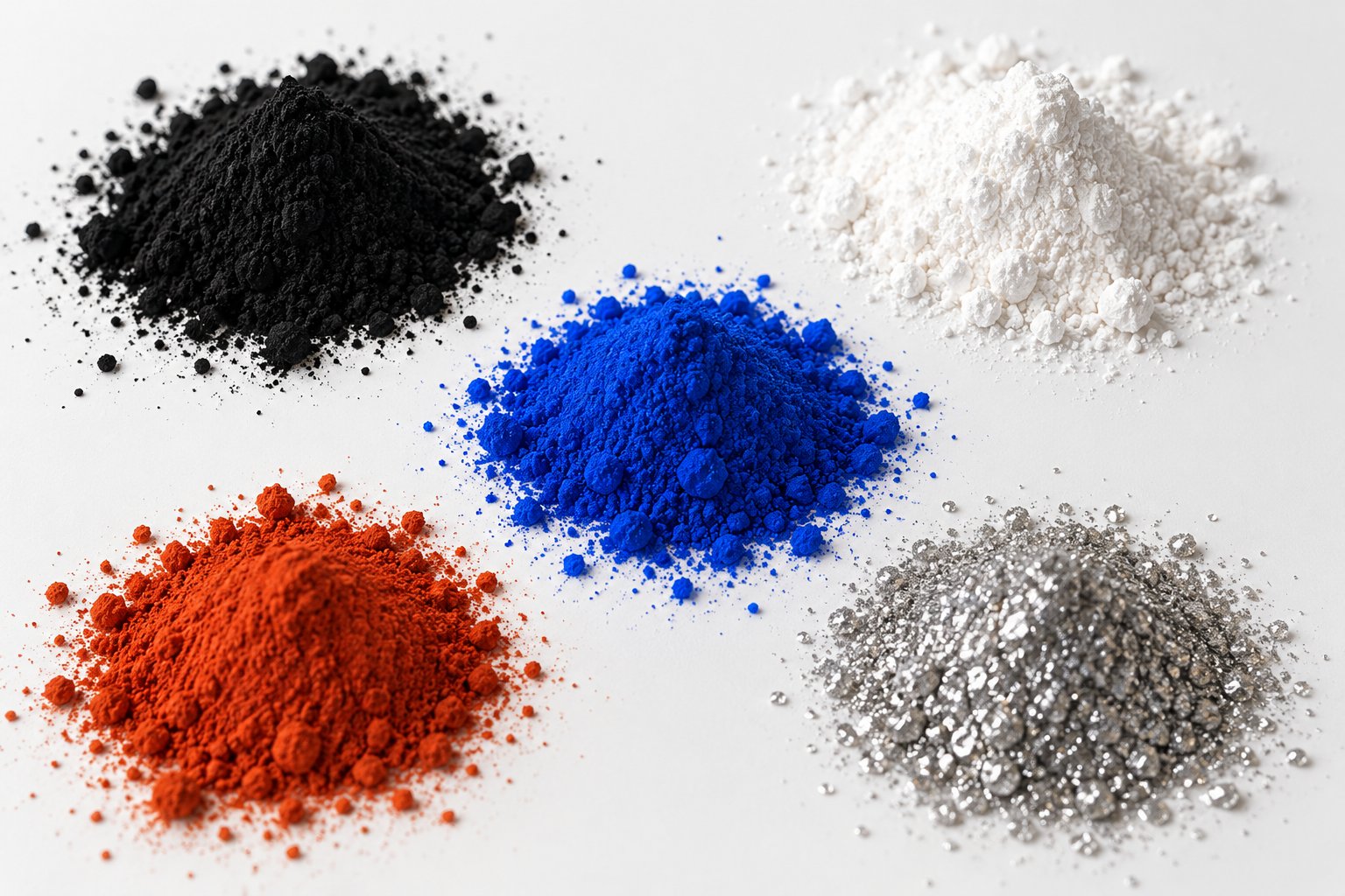
A screw configuration that produces flawless black parts can fail miserably on phthalocyanine blue. A let-down ratio that works perfectly for iron oxide may cause streaking with titanium dioxide. Why? Because the pigment itself — its particle size, surface energy, crystal structure, and mechanical toughness — sets the rules for how much shear is needed, how fast wetting proceeds, and whether distribution requires a gentle touch or an aggressive one. Every polymer masterbatch formulation starts with a colorant, and that colorant's chemistry determines which of the three dispersion stages will be the bottleneck.
Carbon Black Grades and Structure Effects
Carbon black is the most widely used black pigment in plastics, yet treating it as a single material is a recipe for trouble. Grades vary enormously. Ultrafine pigment-grade carbon blacks with primary particles in the 10-20 nm range deliver intense jetness but, as pigment carbon black specialists note, present significant agglomeration challenges and high specific surface areas that resist wetting. Medium-pigment grades (20-40 nm) strike a better balance between tinting strength and dispersibility, making them the workhorse for general PE and PP coloring.
Structure — quantified by DBP oil absorption — adds another layer of complexity. High-structure carbon blacks (DBP above 120 cm³/100 g) form open, branched aggregates that create three-dimensional networks in the polymer melt. These networks improve conductivity and UV protection, but the large internal void volume traps more air, slowing the wetting stage. Low-structure grades (DBP below 80 cm³/100 g) wet and flow more easily, which is why they are preferred in film and fiber applications where melt viscosity must stay low. On a typical masterbatch production line, loading levels for carbon black concentrates in PE or PP can exceed 40%, amplifying every mismatch between grade selection and screw design.
Production method matters too. Furnace-process blacks — the dominant type — offer high thermal stability suited to extrusion and injection molding temperatures. Channel-process blacks develop a dense surface oxide layer during manufacture, giving them better weather resistance but also a more polar surface that can complicate compatibility with non-polar polyolefins unless surface modification or compatibilizers are used.
Titanium Dioxide and Re-Agglomeration Tendency
Titanium dioxide sits at the opposite end of the particle-size spectrum from ultrafine carbon black. Primary particles typically range from 200 to 300 nm — large enough that cohesive forces between individual particles are comparatively low. Sounds like an easy dispersion target, right? In practice, TiO2 presents its own stubborn problem: high particle density (around 4.2 g/cm³ for rutile) means agglomerates settle and pack tightly, and the pigment has a pronounced tendency to re-agglomerate once shear is removed.
Surface treatment plays a decisive role. Rutile-grade TiO2, the standard choice for plastics, is typically coated with alumina, silica, or organic treatments designed to improve wetting and reduce photocatalytic activity. These coatings alter the pigment's surface energy, and as pigment wetting research highlights, a dispersant dose optimized for coated TiO2 can flood or flocculate an organic pigment if reused without adjustment. Anatase grades, less common in plastics, lack the durability of rutile but can be easier to wet in certain aqueous-based systems. For white masterbach formulations — often loaded at 50-70% TiO2 — the sheer volume of pigment magnifies any wetting or re-agglomeration shortfall into visible defects like speck clusters or opacity variation across the part.
Organic and Inorganic Color Pigment Behavior
Organic color pigments bring vivid chroma and high tinting strength, but they are among the most difficult materials to disperse. Phthalocyanine blues and greens are notorious: primary particles can be as small as 30-100 nm, packing enormous surface area into tight agglomerates with very high cohesive energy. The dispersant and anchoring chemistry required for phthalocyanine differs fundamentally from what TiO2 or carbon black needs — a point that coatings formulators reinforce by insisting you name the pigment class before selecting a wetting system. Quinacridone reds and violets are equally demanding, requiring intense dispersive shear and extended residence time to break agglomerates down to their primary crystal size without leaving undispersed specks.
Inorganic color pigments generally behave more forgivingly — with caveats. Iron oxides (reds, yellows, blacks) feature relatively coarse primary particles (200-800 nm) and moderate cohesive forces, making them straightforward to deagglomerate. The trade-off is abrasion: iron oxide is hard enough to accelerate wear on screw elements and barrel liners, a factor that matters in high-throughput operations. Ultramarine blue is the exception in this group. It is shear-sensitive and can decompose under excessive mechanical energy or in acidic environments, releasing sulfur-containing gases that cause odor and surface defects. Processing it demands moderate shear and careful temperature control.
Effect pigments — metallic aluminum flakes and pearlescent mica platelets — flip the mixing priority entirely. These materials rely on their high-aspect-ratio platelet geometry to create shimmer, luster, and angular color shifts. Aggressive dispersive mixing shatters those delicate flakes, destroying the very optical effect you paid a premium to achieve. The extrusion process, as effect-pigment research confirms, pulverizes mica flakes and reduces metallic sparkle when shear is too intense. The recommended approach is gentle distributive mixing — enough to spread the flakes uniformly through the matrix without fracturing them. Particle sizes in the 10-60 micron range are typical, and even small reductions from breakage noticeably degrade luster and brilliance.
| Pigment Category | Primary Particle Size Range | Key Dispersion Challenge | Recommended Mixing Emphasis |
|---|---|---|---|
| Carbon Black | 10-100 nm (varies by grade) | High surface area resists wetting; high-structure grades trap air in branched aggregates; loading levels above 40% amplify viscosity | Extended wetting zone followed by strong dispersive shear; low-structure grades need less dispersive energy |
| Titanium Dioxide | 200-300 nm | High density promotes settling and re-agglomeration; surface treatment chemistry governs wetting speed; very high loadings (50-70%) in white concentrates | Moderate dispersive shear with sustained distributive mixing to prevent re-agglomeration after stress is removed |
| Organic Color Pigments (e.g., phthalocyanine, quinacridone) | 30-100 nm | Extremely high cohesive energy; very small primary particles create tightly bound agglomerates; pigment-specific wetting chemistry required | Intense dispersive shear with adequate residence time; polarity-matched wetting aids essential |
| Inorganic Color Pigments (e.g., iron oxide, ultramarine) | 200-800 nm | Iron oxides are abrasive and accelerate equipment wear; ultramarine blue is shear-sensitive and can decompose, releasing sulfur gases | Moderate dispersive shear for iron oxides (with wear-resistant elements); gentle shear and temperature control for ultramarine |
| Effect Pigments (metallic flakes, pearlescent mica) | 10-60 μm (platelet diameter) | High-aspect-ratio platelets fracture under shear, destroying optical effects; luster depends on intact flake geometry and orientation | Gentle distributive mixing only; avoid high-shear kneading blocks; prioritize stream splitting over stress |
This pigment-by-pigment variation explains why a single "universal" screw design or a one-size-fits-all dispersion aid rarely delivers optimal results. The colorant dictates the process — but the carrier resin that delivers that colorant into the host polymer introduces its own set of variables, particularly around melt flow matching and let-down ratio, where small miscalculations create outsized quality problems.
Carrier Resin Selection and Let-Down Ratio Science
You can select the ideal pigment, design a perfectly sequenced screw, and still end up with streaky, inconsistent parts. How? Two variables that sit upstream of the extruder barrel — the carrier resin inside the masterbatch and the ratio at which it is added to the host polymer — quietly govern whether all that downstream engineering actually works. Masterbatch suppliers and plastic masterbatch manufacturers invest heavily in formulation science precisely because these choices are where compatibility is won or lost. Yet on most production floors, carrier selection is treated as a purchasing decision and let-down ratio as a recipe number, with little thought given to the physics connecting both to dispersion quality.
Melt Flow Index Matching Between Carrier and Host
The carrier resin is the polymer matrix in which pigments are pre-dispersed at high concentration during masterbatch compounding. When that concentrate melts inside the processing machine, the carrier must blend seamlessly into the host polymer so that pigment particles transfer from one matrix to the other. The single most important parameter governing that transfer is the melt flow index — a measure of how easily a polymer flows under a standardized load and temperature.
Imagine dropping a thin, watery syrup into thick honey and stirring. The syrup slides around in pockets rather than blending evenly. Something similar happens when a carrier resin has a significantly higher MFI than the host: the carrier melts into low-viscosity domains that the surrounding, stiffer host polymer cannot efficiently shear. Pigment particles trapped inside those slippery pockets never experience enough stress for full deagglomeration, and the domains themselves resist being folded and redistributed. The result is color streaks aligned with the flow direction and pockets of undispersed concentrate — defects that compatibility specialists link directly to MFI mismatch.
Flip the scenario — a carrier with a much lower MFI than the base resin — and a different failure mode emerges. The carrier pellets resist melting and releasing their pigment load early enough in the process. Unmelted carrier fragments survive deep into the mixing zone or even reach the die, showing up as gels, fish eyes, or hard spots in the finished part.
The practical guideline is straightforward: the carrier MFI should be equal to or slightly higher than the host polymer's MFI, allowing the concentrate to melt readily and disperse freely without creating viscosity pockets that resist shear transfer. For customised masterbatches targeting specific resins — say a high-flow injection-molding polypropylene versus a low-flow blow-molding HDPE — the carrier must be engineered to match each host's rheological window, not a generic middle ground.
Polarity and Viscosity Ratio Considerations
MFI matching addresses flow rate, but it doesn't capture the full picture. Chemical compatibility — specifically polarity — determines whether the carrier and host polymer actually want to mix at a molecular level. A PE-based carrier belongs in polyethylene; a PP-based carrier in polypropylene; a PS-based carrier in polystyrene. Forcing a non-polar polyolefin carrier into a polar engineering resin like PET or nylon invites phase separation, delamination, and catastrophic dispersion failure.
Where polarity gets interesting is in specialty carrier systems. EVA (ethylene-vinyl acetate) copolymers, for example, introduce polar vinyl acetate groups onto a polyethylene backbone. That added polarity improves the carrier's affinity for polar pigments like titanium dioxide and certain organic colorants, helping them wet and release more efficiently inside a PE host. EVA-carrier black masterbatch formulations exploit this same principle — the slight polarity boost aids carbon black wetting without compromising compatibility in PE and PE/EVA blend systems. The trade-off is that EVA carriers soften the final compound slightly, so their use must be balanced against mechanical property targets.
Beyond polarity, the viscosity ratio between the dispersed masterbatch phase and the host matrix influences droplet breakup and distribution. Research on polycarbonate blends with different MFI resins has shown that reducing the viscosity difference between phases improves pigment distribution and lowers color deviation. When the viscosity ratio drifts too far from unity, mixing efficiency drops sharply — one phase simply slides past the other rather than deforming and blending. Optimizing this ratio is part of what separates a generic concentrate from a purpose-built formulation.
Let-Down Ratio Effects on Final Part Quality
The let-down ratio (LDR) — the proportion of masterbatch to base polymer by weight — seems like the simplest variable in the entire process. Add 3% color concentrate to 97% natural resin, blend, and go. Yet incorrect LDRs are among the most frequent causes of quality complaints on production lines, because even small dosing errors cascade through all three dispersion stages.
Typical LDR ranges vary by masterbatch type: color masterbatch commonly runs at 2-5%, additive masterbatch may go up to 10% depending on the active ingredient, and white masterbatch loaded with TiO2 sometimes requires higher ratios to achieve target opacity. These ranges exist because the masterbatch was formulated — carrier chemistry, pigment loading, and dispersion aid package — to perform within a specific dilution window. Step outside that window and the system breaks down.
- Under-dosing the masterbatch: Weak color intensity, insufficient opacity in white formulations, and inadequate additive function (e.g., UV protection below threshold). Operators often compensate by raising temperature or extending cycle time, which risks thermal degradation without fixing the root cause.
- Over-dosing the masterbatch: Excess carrier resin dilutes the host polymer's mechanical properties — tensile strength, impact resistance, and stiffness can all drop measurably. Surplus additive or lubricant migrates to the surface, causing plate-out on molds and dies or blooming on finished parts.
- Inconsistent dosing (shot-to-shot variation): Color shifts between consecutive parts or across a production run. This is especially visible in transparent or translucent applications, where even 0.2% LDR variation produces noticeable shade differences under standard illumination.
- LDR too high for the available mixing length: The processing equipment may not have enough distributive mixing capacity to homogenize the extra concentrate volume, resulting in streaking and concentration gradients even though the dosing is intentional.
- LDR mismatch with carrier MFI: At high let-down ratios, even a modest MFI gap between carrier and host becomes amplified — more carrier volume means more low-viscosity (or high-viscosity) domains competing with the base resin for shear energy.
Getting carrier selection and let-down ratio right eliminates a large share of the defects that processors instinctively blame on pigment quality or machine settings. These two variables define the starting conditions for every dispersion event downstream. Yet even a perfectly matched carrier-host system still depends on what happens inside the barrel — specifically, how screw element geometry translates motor torque into the shear and folding actions that drive deagglomeration and distribution at the micro-scale.
Twin-Screw Configuration Strategies for Optimal Dispersion
Carrier chemistry and let-down ratio define the raw materials entering the barrel, but the screw configuration inside a co-rotating twin-screw extruder determines whether those materials actually become a uniform, defect-free melt. Screw design is the primary lever for translating motor power and barrel heat into controlled pigment breakup and homogenization. Every element along the shaft — its geometry, orientation, and position relative to its neighbors — shapes local shear stress, residence time, and fill level. For anyone asking what is masterbatch processing at its mechanical core, the answer lives in the screw profile.
A typical twin-screw masterbatch line divides the barrel into six functional zones, each defined by the screw elements occupying it: solids conveying, melting and plasticization, dispersive mixing, distributive mixing, venting, and pressure buildup. The same extruder hardware can behave very differently depending on how these zones are configured — a point that CPM's engineering guide on twin-screw design reinforces by noting that element selection controls everything from throughput and melt homogeneity to degassing efficiency and final product quality. Getting the sequence wrong produces specks, streaks, and degraded resin in equal measure.
Kneading Block Geometry and Shear Intensity
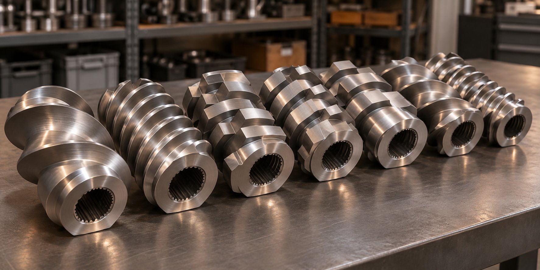
Kneading blocks are the heart of any dispersion-focused screw design. Each block consists of multiple discs stacked on a splined shaft, with every disc offset from the previous one by a defined stagger angle. Three geometric variables — disc width, stagger angle, and number of discs — give process engineers fine-grained control over how aggressively the melt is worked.
Disc width governs how frequently the cross-sectional flow pattern changes along the screw axis. Narrower discs create more interfaces where the melt accelerates and decelerates over short distances, intensifying local pressure fluctuations and shear gradients. That makes narrow-disc kneading blocks the go-to choice for dispersive mixing — exactly what cohesive pigments like phthalocyanine blue or high-structure carbon black need to fracture. Wider discs produce smoother flow paths and lower peak stress, favoring distributive mixing where the goal is gentle spatial rearrangement rather than particle breakup.
Stagger angle is the angular offset between neighboring discs and is arguably the single most influential design variable. At low stagger angles (around 30 degrees forward), the block retains significant forward conveying capacity while still generating moderate shear — a configuration well-suited for initial dispersive work on freshly molten polymer. As the angle increases toward 60 degrees forward, net conveying drops, back-mixing increases, and shear stress climbs sharply. This is where stubborn agglomerates meet their match. Push the angle to 90 degrees (neutral) and forward pumping essentially stops: material oscillates over the block, dramatically extending residence time and driving maximum dispersive energy into the melt. Reverse-stagger kneading blocks actively push material backward, creating intense pressure buildup upstream and the highest stress levels available — ideal for deagglomeration of organic color pigments or heavily loaded carbon black concentrates, but risky for heat-sensitive systems like PVC masterbatch formulations, where the additional viscous heating can trigger degradation.
Number of discs and overall block length determine how many splitting-and-recombining cycles the melt undergoes. Longer blocks increase total energy input and broaden residence time distribution, improving both dispersive and distributive outcomes. The trade-off is higher melt temperature and torque. Shorter blocks deliver more localized effects and are easier to position between conveying elements without spiking thermal load — a practical consideration for polymer masterbatches for healthcare or food-contact applications where regulatory compliance demands tight control of degradation byproducts.
The orientation of the block — forward, neutral, or reverse — completes the picture:
- Forward kneading blocks: Net positive pumping with strong mixing. Useful when throughput must remain high and pressure buildup is acceptable.
- Neutral kneading blocks: Near-zero net conveying. Material dwells longer, intensifying both dispersive and distributive action. Common in the primary mixing zone.
- Reverse kneading blocks: Negative conveying effect. Creates strong upstream pressure, generates the highest shear and stress peaks, and forms effective melt seals. Critical for high-intensity deagglomeration and for isolating vent zones — but demands careful thermal management.
Combining these variables lets engineers tune a single barrel section from gentle folding to aggressive particle fracture simply by swapping elements. A narrow-disc, 60-degree forward kneading block followed by a neutral block, for instance, delivers a sharp dispersive hit and then holds the material in a back-mixing zone long enough to finish the job — a pairing commonly used for titanium dioxide concentrates where re-agglomeration is a concern.
Vent-Zone Configuration for Volatile Removal
Pigment dispersion and volatile removal are often treated as separate engineering problems, but in twin-screw masterbatch production they share the same barrel real estate. Moisture trapped in hygroscopic carrier resins, adsorbed volatiles on pigment surfaces, and residual solvents from recycled feedstock all need to be extracted before the melt reaches the die. If they are not, the volatiles nucleate bubbles, surface blisters, and foaming at the strand die — defects that mimic dispersion failures and obscure their root cause.
A functional vent zone relies on a pressure seal upstream of an open barrel port. Reverse or neutral kneading elements positioned just before the vent create a fully filled, pressurized section that isolates the low-pressure vent region from the rest of the barrel. Material forced over this restriction enters a partially filled zone where conveying elements with large pitch reduce pressure rapidly. That sudden decompression superheats entrained volatiles, flashing them out of the melt and exposing fresh surface area as the screw continually renews the melt film. Vacuum applied to the barrel port pulls the released vapors away.
As devolatilization specialists at Plastics Technology explain, the downstream seal is equally important: if the restriction is too tight or too close to the vent, or if throughput is too high relative to screw speed, the filled melt section backs up into the vent opening, flooding it and blocking the vapor takeoff piping. Designing the downstream seal — typically another set of kneading blocks or a restrictive conveying element — requires balancing fill length against throughput rate and screw RPM. A good rule of thumb is that each vent stage can reduce volatile concentration by roughly an order of magnitude, so multi-vent configurations are standard for heavily loaded or moisture-sensitive formulations.
Vent-zone performance degrades over time as kneading elements and barrel liners wear, widening clearances and weakening the melt seal. When operators notice increasing porosity in strands or rising moisture content in pellets, the root cause is often worn elements rather than a change in raw material quality.
Matching Screw Elements to Pigment and Polymer Systems
The real art of twin-screw configuration lies in matching element selection to the specific pigment and polymer combination on the production schedule. No single profile works for every formulation. Consider the contrast between a 40% carbon black PE concentrate and a pearlescent effect masterbatch in the same polyethylene host: the carbon black demands aggressive dispersive kneading (narrow discs, high stagger angles, possibly a reverse block) followed by a thorough distributive section, while the effect pigment requires almost no dispersive action at all — only gentle tooth-type mixing elements (TME or ZME designs) that split and recombine the melt without fracturing delicate mica platelets.
Screw speed and throughput interact with element geometry to modulate specific mechanical energy (SME) — the total mechanical energy input per unit mass of material. SME is the single best predictor of dispersion outcome in a given formulation: too low and agglomerates survive, too high and polymer chains degrade and pigments shift color. Increasing screw speed at constant throughput raises SME by intensifying shear rate across every kneading block. Increasing throughput at constant speed lowers SME by reducing residence time in high-shear zones. Process engineers adjust both levers in tandem, using torque readouts and melt temperature probes to stay inside the processing window for each recipe.
The table below maps each barrel zone to its typical element type, functional role, and the application context where it matters most:
| Screw Zone | Element Type | Function | Typical Application |
|---|---|---|---|
| Solids Conveying | Large-pitch conveying elements | Grip pellets or powder; transport material forward with minimal compression | All masterbatch types; extra-large pitch for low-bulk-density powders or regrind |
| Melting / Plasticization | Decreasing-pitch conveying elements transitioning to mild kneading blocks (30° forward) | Gradually compress and melt polymer through barrel contact and viscous shear | Polyolefin-based color and additive concentrates; gentle profile for PVC masterbatch to limit thermal history |
| Dispersive Mixing | Narrow-disc kneading blocks at 60° forward, neutral, or reverse stagger | Generate shear stress exceeding agglomerate cohesive forces; fracture pigment clusters | High-structure carbon black, phthalocyanine blue, quinacridone reds; heavily loaded TiO2 white concentrates |
| Distributive Mixing | Wide-disc kneading blocks at low stagger; TME/ZME toothed mixing elements | Split, reorient, and recombine melt streams to eliminate concentration gradients without high stress | Effect pigments (metallic, pearlescent); fiber-filled compounds; polymer masterbatches for healthcare where degradation byproducts must be minimized |
| Venting / Devolatilization | Reverse or neutral kneading block (melt seal) followed by large-pitch conveying elements under open barrel port | Create pressure differential for vacuum removal of moisture, volatiles, and trapped air | Hygroscopic carriers (nylon, PET-based), recycled feedstock with residual contaminants, high-moisture pigments |
| Pressure Buildup / Metering | Tight-pitch conveying elements | Build stable die pressure for consistent strand or pellet output | All formulations; tighter pitch for high-viscosity or highly filled systems requiring die stability |
Because these zones are built from modular, individually replaceable segments, process engineers can reconfigure mixing sections without replacing the entire screw assembly. That modularity is what makes iterative optimization practical — swap a 60-degree kneading block for a 30-degree one, extend a distributive section by adding a toothed element, or replace a worn reverse block whose clearances no longer hold a reliable melt seal. Suppliers of modular screw segments, such as NANHAIYA, offer catalogs spanning conveying elements, kneading blocks at various stagger angles and disc widths, and specialty mixing elements, allowing engineers to review element geometry, shaft matching, and wear conditions before ordering targeted replacements rather than full screw sets.
Screw configuration sets the mechanical framework for masterbatch dispersion, but it does not operate in isolation. Even a perfectly tuned element profile benefits from — and in many formulations depends on — chemical assistance at the pigment-polymer interface. That assistance comes from a category of additives designed specifically to accelerate wetting, reduce inter-particle friction, and lower the shear threshold for deagglomeration: dispersion aids.
Dispersion Aids Compared Without Brand Bias
A precisely configured screw profile delivers the mechanical energy, but chemistry at the pigment-polymer interface decides how efficiently that energy is used. Dispersion aids are low-molecular-weight additives designed to accelerate wetting, reduce the stress threshold for agglomerate breakup, and prevent re-agglomeration downstream. Every masterbatch supplier stocks at least one or two types, yet the category is broader than most formulators realize — and choosing the wrong aid for a given pigment-resin system can introduce as many problems as it solves. Here is a vendor-neutral look at the five major families, what each one actually does inside the melt, and how to match them to your application.
Wax-Based Dispersion Aids and Their Mechanisms
Polyethylene waxes are the most widely used dispersion aids in polyolefin-based masterbatch production. These are low-molecular-weight polyethylene chains — typically 1,000 to 10,000 g/mol — that melt early in the barrel, flow readily around pigment surfaces, and displace trapped air from agglomerate voids. By forming a thin, low-viscosity film between pigment particles and the surrounding polymer melt, PE wax effectively lowers the local interfacial tension and accelerates Stage 1 wetting. As industry processing data confirms, PE wax also reduces overall melt viscosity in the mixing zone, meaning more of the extruder's shear energy reaches the agglomerate rather than being consumed by bulk polymer deformation. Typical loading ranges fall between 0.5% and 3.0% of total batch weight — enough to boost wetting and flow without significantly altering the mechanical properties of the final part.
The key limitation? Standard PE wax is non-polar. It works beautifully in LDPE, HDPE, and LLDPE systems, where chemical affinity between wax and host is high. Pair it with a polar pigment like titanium dioxide, though, and the wax molecules would rather interact with the polymer than the pigment surface — reducing the very wetting benefit you installed it to provide.
Oxidized polyethylene waxes solve this polarity gap. By introducing carboxyl (-COOH) and hydroxyl (-OH) functional groups onto the PE backbone through controlled oxidation, these waxes gain enough polar character to anchor onto the surfaces of polar pigments — TiO2, certain organic colorants, and inorganic fillers like calcium carbonate. The added polarity improves pigment-wax affinity while the polyethylene backbone maintains compatibility with the polyolefin carrier and host. Think of oxidized PE wax as a molecular bridge: one end grips the pigment, the other dissolves into the polymer. For white masterbatch concentrates loaded at 50-70% TiO2, oxidized PE wax is often the default choice because it simultaneously wets the pigment and prevents the re-agglomeration that unmodified PE wax cannot fully suppress.
Polypropylene waxes follow the same low-viscosity, early-melting logic as PE waxes but are preferred whenever the carrier and host polymer are both polypropylene. Why does that distinction matter? Compatibility. A PE wax molecule inside a PP melt is a foreign phase — it can migrate to the surface, cause haze, or create weak interfacial boundaries. A PP wax integrates seamlessly into the PP matrix, delivering the wetting and flow benefits without introducing phase-separation artifacts. For plastic master batch manufacturers running dedicated PP lines — automotive components, fiber-grade concentrates, rigid packaging — PP wax eliminates a compatibility variable that PE wax would add.
EBS and Metal Stearate Functionality
Ethylene bis-stearamide (EBS) is a synthetic wax-like amide that serves double duty. Externally, it acts as a lubricant, reducing friction between the melt and barrel or die surfaces. Internally, it functions as a dispersant by coating pigment particles and reducing the inter-particle friction that holds agglomerates together. That dual action makes EBS especially useful in high-loading formulations — carbon black concentrates above 30%, for instance — where inter-particle contact is so frequent that agglomerates can re-form almost as fast as the screw breaks them apart. EBS raises the slip between neighboring particles, keeping them separated long enough for the distributive mixing section to spread them uniformly.
EBS is compatible with a wide range of thermoplastics — PE, PP, PS, ABS, and engineering resins — making it a versatile option for masterbatch compounders running mixed production schedules. Typical loading is 0.2-1.0% by weight. The main caution: excessive EBS can bloom to the surface, creating a whitish haze on dark-colored parts or interfering with downstream printing and bonding operations.
Metal stearates — most commonly zinc stearate and calcium stearate — bring a different functional profile. Like EBS, they lubricate and reduce friction. Unlike EBS, they also act as acid scavengers, neutralizing residual hydrochloric acid (HCl) or other acidic byproducts generated during processing. This acid-scavenging role makes metal stearates particularly valuable in PVC masterbatch formulations, where thermal degradation of the PVC chain releases HCl that would otherwise catalyze further degradation in a destructive feedback loop. Calcium stearate is the workhorse in PVC systems; zinc stearate is favored where faster initial stabilization is needed. Both contribute to pigment wetting through their surfactant-like molecular structure — a polar metal-carboxylate head group that interacts with pigment surfaces and a long hydrocarbon tail that blends into the polymer melt. Loading levels typically range from 0.3% to 1.5%.
Selection Criteria for Different Polymer Systems
With five families on the table, how do you pick the right one? Four criteria drive the decision:
- Pigment polarity: Non-polar pigments like carbon black pair naturally with standard PE or PP wax. Polar pigments — TiO2, iron oxides, most organic colorants — benefit from oxidized PE wax, EBS, or metal stearates that can anchor onto the pigment surface.
- Carrier resin type: The dispersion aid must be chemically compatible with the carrier and host polymer. PE wax in PE, PP wax in PP, and metal stearates in PVC are baseline matches. Cross-polymer use (e.g., PE wax in PP) is possible but demands testing for migration and haze.
- Processing temperature window: The aid must melt and activate before the primary mixing zone but remain thermally stable through the entire barrel. PE waxes typically melt between 100-130 degrees C; PP waxes between 140-160 degrees C; EBS around 140-145 degrees C. Selecting an aid whose melting point is too close to the barrel temperature in the feed zone can cause premature melting and feeding problems; one that melts too late misses the wetting window entirely.
- Regulatory requirements: Food-contact, pharmaceutical, and medical applications impose strict limits on extractable and migratable substances from packaging polymers. Research on chemical migration from packaging materials highlights that additives including lubricants, stabilizers, and waxes can transfer into food matrices, especially under elevated temperature and extended contact. Regulations such as EU 10/2011 and FDA 21 CFR 178 set specific migration limits for indirect food additives. Any dispersion aid used in a food-contact or healthcare masterbatch must appear on the relevant positive list and meet its specific migration limit — a compliance step that sometimes eliminates otherwise attractive options.
| Dispersion Aid Type | Primary Mechanism | Compatible Polymers | Typical Loading Range |
|---|---|---|---|
| Polyethylene Wax | Lowers melt viscosity around pigment; accelerates wetting by displacing air; forms low-friction film between particles | LDPE, HDPE, LLDPE, EVA | 0.5 - 3.0% |
| Oxidized Polyethylene Wax | Polar functional groups (-COOH, -OH) anchor onto polar pigments; bridges pigment surface to non-polar carrier; prevents re-agglomeration | PE, PP (with polarity-matching benefit for TiO2, CaCO3, organic pigments) | 0.5 - 2.5% |
| Polypropylene Wax | Same wetting and viscosity-reduction function as PE wax; full compatibility with PP carrier and host avoids migration and haze | PP, PP copolymers | 0.5 - 3.0% |
| EBS (Ethylene Bis-Stearamide) | External lubricant reduces melt-metal friction; internal dispersant coats particles and reduces inter-particle friction; prevents re-agglomeration at high loading | PE, PP, PS, ABS, PA, PET, engineering resins | 0.2 - 1.0% |
| Metal Stearates (Zinc, Calcium) | Surfactant-like structure wets pigment surfaces; lubricates melt; scavenges residual acids (HCl in PVC); provides early-stage thermal stabilization | PVC (primary); PE, PP, PS (secondary) | 0.3 - 1.5% |
No single dispersion aid covers every formulation. Many production-proven recipes combine two — an oxidized PE wax for pigment wetting plus EBS for inter-particle lubrication, for example — to address multiple dispersion stages simultaneously. The key is treating aid selection as a formulation decision rooted in pigment chemistry and polymer compatibility, not as a generic "add 1% wax" checkbox.
Even with the right aid at the right loading, the final arbiter of dispersion quality is the finished part itself. Streaks, specks, haze, and color shifts each point back to a specific failure in the wetting-deagglomeration-distribution sequence — and diagnosing which failure occurred is the difference between a quick fix and a week of trial-and-error screw changes.
Diagnosing Every Common Dispersion Defect
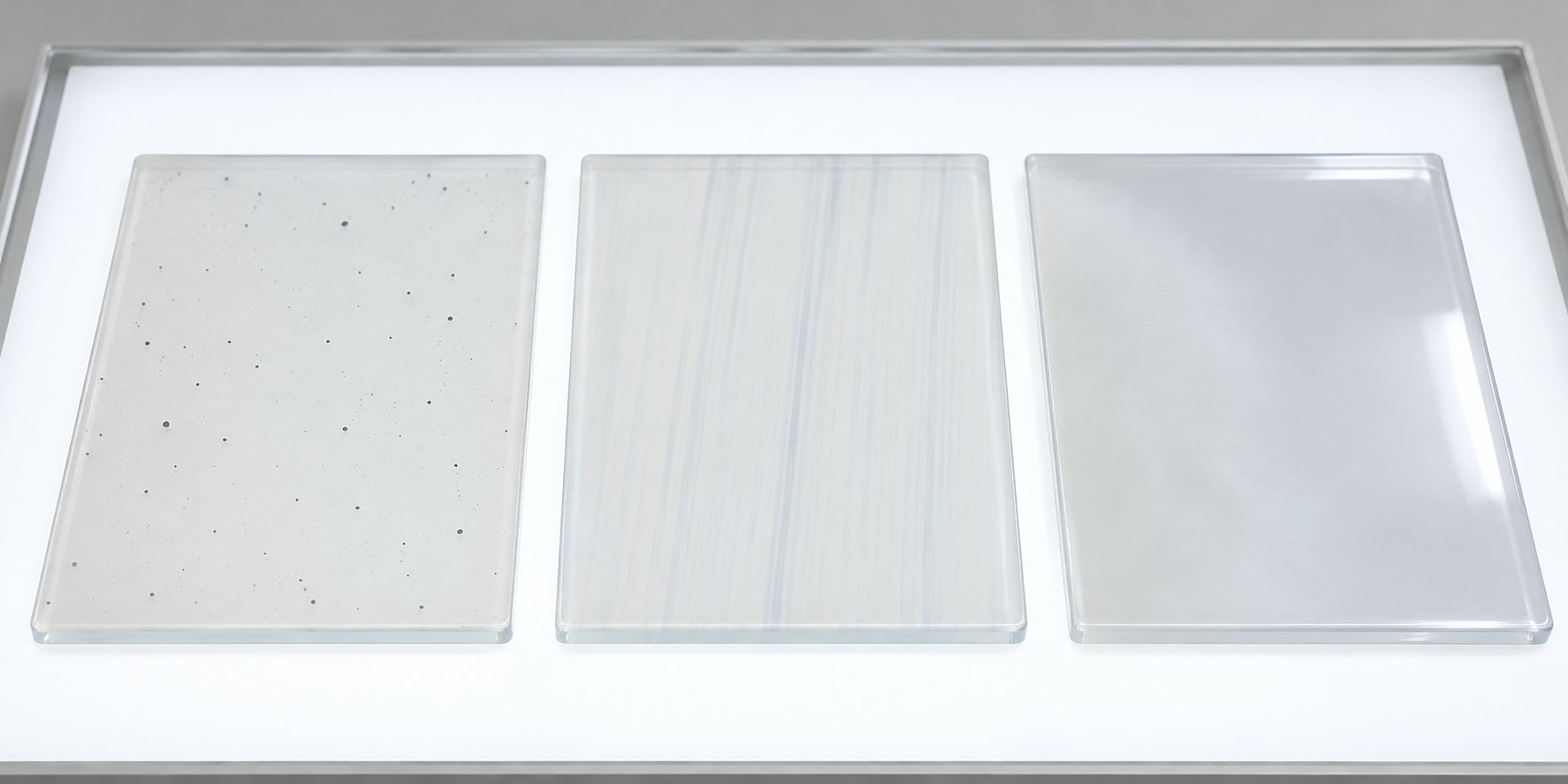
The right dispersion aid at the right loading, a well-sequenced screw profile, a carrier-host match that checks every box — and yet a defect appears on the finished part. What went wrong? More importantly, which stage of the wetting-deagglomeration-distribution sequence failed? Every dispersion defect leaves a visual fingerprint, and reading that fingerprint correctly is what separates a ten-minute fix from days of blind trial and error. Below is a systematic taxonomy of the six most common masterbatch dispersion defects, organized by root cause rather than by the product type where they happen to show up.
Agglomerate-Related Defects and Specking
Specking is the defect most directly linked to incomplete deagglomeration. You'll see it as dark or colored spots — sometimes as small as 50 microns, sometimes large enough to catch with the naked eye — scattered across the part surface or embedded just below it. Each speck is an undispersed pigment agglomerate that survived the dispersive mixing zone intact. Root causes range from insufficient shear stress in the kneading section to oversized agglomerates in the incoming masterbatch plastic concentrate, or outright contamination from degraded material lodged in dead spots within the barrel or die.
Fish eyes are a close cousin. These gel-like, translucent spots usually originate not from pigment but from undispersed carrier resin — small domains of polymer that never fully melted and integrated into the host matrix. Cross-linked material from degraded resin or contamination in recycled feedstock produces the same visual signature. As white masterbatch defect analyses note, moisture or contamination in raw materials combined with low melt temperature frequently leads to these spot-type defects, especially in thin films and glossy molded parts where even tiny inclusions are impossible to hide.
Surface haze rounds out the agglomerate family. Instead of discrete spots, you get a diffuse loss of gloss — the part looks dull or milky where it should be shiny. The cause is near-surface pigment agglomerates that are too small to register as individual specks but large enough to scatter incident light. Think of it as a population of marginal agglomerates: they passed through the dispersive zone partially broken down but never reached primary particle size. The light-scattering effect is proportional to the number and size of these residual clusters, which is why surface haze intensifies as pigment loading increases or as dispersive shear decreases.
Flow-Related Color Defects in Molded Parts
Color streaking is the hallmark of poor distributive mixing. Unlike specks, which are point defects, streaks are directional — they follow the melt flow path and appear as bands of lighter or darker color against the surrounding matrix. The root cause is almost always a concentration gradient: pigment-rich and pigment-poor regions that the distributive mixing section failed to homogenize. MFI mismatch between carrier and host amplifies the problem, as low-viscosity carrier domains slide through the melt without being folded and redistributed. Incorrect let-down ratio — especially under-dosing — can produce the same visual pattern, and as injection molding defect specialists point out, streaks that appear in repeatable positions usually trace to process-side factors like mixing performance, dosing accuracy, or flow behavior rather than to the master batches themselves.
Gate blush catches many processors off guard because it seems to appear at the very spot where shear should be highest — the injection gate. The symptom is a whitening, dulling, or localized color shift radiating outward from the gate. What's happening is counterintuitive: the extreme shear rate at a narrow gate can actually re-agglomerate marginally dispersed pigment particles. Particles that were barely separated during compounding get forced back together under the intense extensional and shear flow at the gate entrance, creating a concentrated zone of loosely bound clusters that scatter light differently from the well-dispersed melt downstream. Widening the gate, reducing injection speed, or — more fundamentally — improving upstream dispersive mixing so particles are fully separated rather than marginally so, are the standard corrective paths.
Weld-line color variation appears wherever two melt flow fronts meet inside a mold cavity — around pins, holes, or inserts. The color along the weld line looks different from the surrounding surface. This defect is driven by pigment orientation and distribution: as two fronts converge, pigment particles — especially anisotropic ones like effect flakes or elongated organic crystallites — align parallel to the weld interface rather than randomly. That alignment changes how light interacts with the surface, producing a visible line even when dispersion quality is otherwise good. Mold design and process optimization — gate position, melt temperature, injection speed — are the primary levers, along with pigment selection that favors equiaxed particles less prone to orientation effects.
Nearly every masterbatch dispersion defect traces back to a failure in one of the three dispersion stages: specks and haze signal incomplete deagglomeration, streaks and shot-to-shot color drift reveal poor distribution, and fish eyes or persistent gels point to a wetting failure where polymer melt never penetrated the agglomerate core.
A Systematic Cause-Effect-Remedy Framework
Rather than chasing each defect independently, the most effective diagnostic approach maps every symptom to its originating dispersion stage, then selects the corrective action that addresses that stage directly. The table below consolidates all six defects into a single reference:
| Defect | Visual Symptom | Primary Root Cause | Corrective Action |
|---|---|---|---|
| Specking | Discrete dark or colored spots on surface or embedded beneath it; visible to naked eye or under low magnification | Insufficient dispersive shear; oversized pigment agglomerates in incoming concentrate; contamination from degraded material in barrel dead spots | Increase dispersive mixing intensity (narrower kneading discs, higher stagger angle); verify incoming masterbatch filter pressure value; purge barrel and die dead zones; check for worn screw elements reducing shear |
| Color Streaking | Directional bands of lighter or darker color following the melt flow path; visible in films, sheets, and molded parts | Poor distributive mixing; MFI mismatch between carrier and host resin; incorrect let-down ratio creating concentration gradients | Extend distributive mixing section (add toothed or gear-type elements); match carrier MFI to host; verify dosing accuracy and LDR; check screw speed-to-throughput ratio |
| Fish Eyes | Small, gel-like translucent spots with a raised or lens-shaped profile; most visible in films and transparent parts | Undispersed carrier resin that never fully melted; cross-linked or degraded polymer fragments; moisture in hygroscopic carrier or feedstock | Increase melt temperature in plasticization zone; pre-dry carrier resin and host polymer; check for degraded material buildup on screw or die; replace contaminated feedstock |
| Gate Blush | Whitening, dulling, or color shift radiating outward from injection gate area | High shear at narrow gate re-agglomerates marginally dispersed pigment; extensional flow forces partially separated particles back together | Improve upstream dispersive mixing to achieve full deagglomeration; widen gate cross-section; reduce injection speed; optimize melt and mold temperature |
| Weld-Line Color Variation | Visible color difference along the line where two melt flow fronts converge; often appears as a darker or lighter seam | Anisotropic pigment particles align parallel to the weld interface, altering light interaction; poor melt-front temperature at convergence point | Select equiaxed pigment particles less prone to orientation; optimize gate position and number; raise melt and mold temperature to improve flow-front fusion; adjust injection speed profile |
| Surface Haze | Diffuse loss of gloss; dull or milky appearance instead of expected sheen; no discrete spots visible | Near-surface pigment agglomerates too small for visible specks but large enough to scatter light; incomplete dispersive mixing at moderate severity | Increase dispersive shear or residence time in kneading zone; add or increase oxidized PE wax or EBS to improve wetting; reduce pigment loading if agglomerates are marginal; verify filter pressure value of incoming masterbatch |
Notice the pattern: corrective actions for specking, haze, and gate blush all point upstream toward the dispersive mixing stage, while streaking and weld-line variation point toward distributive mixing and mold-level flow management. Fish eyes straddle the boundary, often tracing all the way back to incomplete wetting. That stage-specific logic turns a seemingly overwhelming list of possible defects into a manageable diagnostic tree — identify the symptom, map it to a stage, and direct corrective effort precisely where it will have the most impact.
Identifying defects by eye, however, is reactive by nature. A speck that reaches a customer already represents a failure. The next logical step is building a measurement and quality-control system that catches dispersion problems before they leave the production floor — and feeds that data back into process and equipment decisions in a continuous improvement loop.
Measuring Dispersion Quality and Closing the Feedback Loop
A defect taxonomy tells you what went wrong after the fact. A measurement system tells you something is drifting before defective parts ever reach a customer. Yet on many production floors — even at a well-equipped masterbatch company — quality control for dispersion remains surprisingly informal: a visual check of pellet color, maybe a quick glance at a pressed film under a desk lamp. That gap between what could be measured and what actually gets measured is where scrap, rework, and customer complaints quietly accumulate. Closing it requires matching the right test method to the right dispersion stage and, critically, feeding results back into process and equipment decisions fast enough to matter.
Filter Pressure Value Testing and Industry Standards
If you could pick only one quantitative test for masterbatch dispersion, the filter pressure value (FPV) test would be it. Standardized under EN 13900-5 — and now adopted internationally as ISO 23900-5 — FPV testing works on a straightforward principle: a known mass of masterbatch is melted, homogenized in a single-screw extruder, and pushed through a fine screen pack at a constant volume flow controlled by a melt pump. Undispersed agglomerates, gels, and contaminants progressively clog the screen, restricting flow. Because the volume flow is held constant, that restriction shows up as a pressure rise upstream of the filter. The FPV is then calculated as:
FPV = (Pmax - Pstart) / m, where m is the pigment mass in the test sample.
A low FPV means the melt passed through the screen with minimal obstruction — agglomerates were broken down effectively. A high FPV means significant undispersed material survived. What counts as "acceptable" depends entirely on the end application. Fiber spinning for ultra-fine deniers demands FPV values well below those tolerated in injection-molded thick-wall parts, because even a single surviving agglomerate can break a 15-micron filament. Blown film sits in between: biaxial orientation during bubble inflation stretches marginal agglomerates into visible streaks, making the process less forgiving than injection molding but more tolerant than spinning.
FPV testing directly targets Stage 2 of the dispersion model — deagglomeration. It catches agglomerates that the dispersive mixing zone failed to fracture. It does not, however, tell you much about spatial uniformity. A batch could pass FPV testing with flying colors yet still produce streaky parts if distributive mixing was inadequate. That distinction is why FPV should never be the only metric in a QC program.
Optical and Spectrophotometric QC Methods
Microscopy-based evaluation fills the visual gap that FPV cannot reach. The method is simple: press a thin film from the masterbatch let-down, place it on a light table or microscope stage, and compare the visible particle population against a standardized set of reference images. Rating scales — often running from 1 (heavy agglomeration) to 5 (fully dispersed) — give incoming QC inspectors a fast, low-cost screening tool. No specialized lab equipment is required beyond an optical microscope and the reference chart. Microscopy catches both deagglomeration failures (large, dark specks) and distribution failures (uneven pigment density across the film area), making it a versatile first line of defense.
For anyone wondering what is master batch quality in numerical terms, spectrophotometric color measurement provides the answer. A spectrophotometer reads the L*, a*, and b* coordinates of a pressed plaque or film sample in the CIELAB color space, then compares those coordinates against a standard to calculate Delta E (ΔE) — the single-number expression of total color difference. As color science resources explain, a ΔE below 1.0 is imperceptible to the human eye, values between 1.0 and 2.0 are barely noticeable, and anything above 3.0 is clearly visible and typically unacceptable in commercial production. Tracking ΔE batch over batch reveals distribution drift: if pigment is not being spread uniformly through the melt, relative tinting strength drops, L* shifts, and ΔE creeps upward — even when the same raw materials and recipe are in use.
Relative tinting strength measurement adds another layer. By comparing the color strength of a production sample against a reference standard at the same pigment loading, you quantify whether the dispersion process is extracting the full optical potential from the pigment. A 5% drop in tinting strength, for example, often signals that agglomerates are surviving in sizes too small for FPV screens to catch but large enough to scatter light internally rather than absorbing or reflecting it efficiently. This metric is particularly valuable for masterbatch para polietileno film applications, where even minor tinting-strength variation translates into visible shade differences on a packaging line.
Particle size distribution analysis — via laser diffraction or automated image analysis — sits at the R&D end of the sophistication spectrum. These instruments map the full population of particle sizes in a dispersion, revealing not just the median but the tail of the distribution where problematic oversized particles hide. Laser diffraction is fast and repeatable; image analysis adds shape information that helps distinguish true pigment agglomerates from carrier resin gels. Both tools are invaluable for new-product development and root-cause investigations but are rarely practical for routine production-floor QC due to sample preparation time and instrument cost.
Ranking these methods from simplest to most sophisticated gives production teams a clear adoption path:
- Visual pellet and part inspection — no equipment required; catches gross defects only; subjective and operator-dependent.
- Optical microscopy with reference-image rating — light microscope plus standardized chart; detects both agglomerate and distribution failures in pressed films; low cost and fast.
- Spectrophotometric ΔE and tinting strength — benchtop spectrophotometer; quantifies color consistency and distribution quality; batch-traceable data for SPC charts.
- Filter pressure value (FPV) testing per ISO 23900-5 — dedicated lab extruder with melt pump and screen pack; industry-standard quantitative deagglomeration metric; requires capital investment but provides the most reproducible dispersion number available.
- Particle size distribution analysis (laser diffraction or image analysis) — laboratory instruments mapping full size populations; best suited for R&D, supplier qualification, and failure analysis rather than daily QC.
Each method maps onto the three-stage dispersion model in a specific way. FPV is the definitive deagglomeration test — it physically traps particles that dispersive mixing failed to break. Spectrophotometric color strength and ΔE are primarily distribution indicators — they detect the optical consequences of uneven pigment spread. Microscopy bridges both stages, offering a visual snapshot that can reveal agglomerates and concentration gradients simultaneously. A robust QC program layers at least two of these methods — typically microscopy for rapid screening and FPV or spectrophotometry for quantitative records — so that neither deagglomeration nor distribution failures slip through undetected.
Adjusting Process and Equipment When Quality Drifts
Data without action is just paperwork. The real value of a measurement program emerges when QC results trigger specific, targeted corrections before scrap accumulates. Imagine FPV values trending upward over several production runs while the recipe and raw materials remain unchanged. The most common culprit is mechanical: kneading elements in the dispersive zone have worn down, widening clearances and reducing the peak shear stress the melt experiences. A barrel liner worn beyond tolerance has the same effect — the gap between screw flight and wall opens up, and shear intensity drops below the threshold needed to fracture stubborn agglomerates.
Similarly, a gradual decline in relative tinting strength — visible as a slow creep in ΔE values on the SPC chart — often points to distributive mixing elements that have lost their edge geometry. Toothed mixing elements (TME or ZME types) rely on precise tip profiles to split and recombine the melt stream. As those tips round off from abrasive pigments like iron oxide or TiO2 at high loadings, the number of effective stream-splitting events per revolution drops, and concentration gradients survive into the final pellet.
Corrective response follows a logical sequence. First, verify that raw materials — pigment lot, carrier resin, dispersion aid — have not changed. If they have not, pull the screw and inspect element wear. Measure tip clearances against original specifications. Check kneading disc faces for grooving or rounding. Evaluate barrel liner bore with a go/no-go gauge. When wear is confirmed, the fix is component replacement, not wholesale screw redesign. Modular twin-screw programs exist precisely for this scenario: individual kneading blocks, toothed elements, or conveying segments slide off the splined shaft and new ones slide on. Suppliers of modular screw segments such as NANHAIYA review element geometry, shaft matching, filler content, and wear conditions to recommend targeted replacements — a single worn 60-degree kneading block swapped for a fresh one, or a distributive toothed element upgraded to a more aggressive tooth profile to compensate for a recipe change.
Equipment intervention is one piece of the feedback loop. Process parameter adjustments — raising screw speed to increase SME, reducing throughput to extend residence time in the mixing zone, or adding a second vent stage to address moisture-related defects — complement hardware changes. The goal is a closed-loop system where QC data drives both process and equipment decisions in near-real time, preventing the slow quality erosion that turns a marginal dispersion process into a chronic defect generator.
Dispersion quality also varies with the downstream forming process, and QC thresholds must reflect that reality. Injection molding applies high shear at the gate, which can further break marginal agglomerates — or re-agglomerate barely separated particles, as the gate blush discussion showed. Blown film imposes biaxial orientation that stretches any residual concentration gradient into a visible streak, demanding tighter incoming FPV limits. Cast film and sheet extrusion are somewhat more forgiving but still expose haze and specks on glossy surfaces. Fiber spinning sits at the extreme: ultra-fine denier filaments have cross-sections measured in tens of microns, leaving zero tolerance for surviving agglomerates. A single undispersed particle can cause a filament break, line stoppage, and downstream quality cascade. Setting a universal FPV limit across all these applications is meaningless — each process needs its own threshold, derived from empirical correlation between lab FPV values and actual part defect rates.
Building this kind of application-specific, data-driven QC framework transforms dispersion quality from an art practiced by experienced operators into a repeatable engineering discipline — one where every measurement points to a cause, every cause maps to a dispersion stage, and every stage links to specific process parameters and equipment configurations that can be adjusted, documented, and controlled.
Frequently Asked Questions About Masterbatch Dispersion
1. What is masterbatch dispersion and why does it matter?
Masterbatch dispersion refers to breaking down concentrated pigment or additive agglomerates within a carrier resin and spreading them uniformly throughout a host polymer during melt processing. It matters because incomplete dispersion directly causes visible defects such as specks, color streaks, surface haze, and mechanical weak points in finished plastic parts. Even premium-grade pigments will underperform if the dispersion process — which follows three sequential stages of wetting, deagglomeration, and distribution — is not properly managed through correct screw configuration, carrier resin matching, and appropriate dispersion aids.
2. What is the difference between dispersive mixing and distributive mixing in masterbatch processing?
Dispersive mixing uses high shear stress in narrow-gap zones — such as wide kneading disc blocks — to physically fracture pigment agglomerates into smaller particles or primary units. Distributive mixing, by contrast, operates at lower stress levels and relies on repeated stream splitting, reorientation, and recombination to spread already-broken-down particles evenly throughout the polymer matrix. Both must be sequenced correctly in a twin-screw extruder: dispersive action first to reduce particle size, then distributive action to eliminate concentration gradients. Neglecting either stage leads to distinct defect types — specks from poor dispersive mixing or streaks from inadequate distributive mixing.
3. How do you measure masterbatch dispersion quality on the production floor?
The industry-standard quantitative method is filter pressure value (FPV) testing per ISO 23900-5, where masterbatch is extruded through a fine screen and the resulting pressure rise indicates how many undispersed agglomerates remain. For faster daily screening, optical microscopy of thin pressed films rated against reference images detects both agglomerates and uneven pigment concentration. Spectrophotometric measurements of Delta E and relative tinting strength quantify batch-to-batch color consistency and distribution quality. The most effective QC programs layer at least two methods — one targeting deagglomeration failures and another targeting distribution issues — with thresholds tailored to the specific downstream process such as film, molding, or fiber spinning.
4. Why does carrier resin MFI mismatch cause dispersion problems?
When the carrier resin has a significantly higher melt flow index than the host polymer, it melts into low-viscosity pockets that the stiffer surrounding resin cannot efficiently shear. Pigment particles trapped in those slippery domains never experience enough stress for full deagglomeration, producing color streaks and undispersed concentrate spots. Conversely, a carrier with too-low MFI resists melting early enough, leaving unmelted fragments that appear as gels or fish eyes in finished parts. The practical guideline is to select a carrier MFI equal to or slightly higher than the host resin so concentrate melts readily and disperses without creating viscosity mismatches that starve pigment particles of shear energy.
5. Which pigments are hardest to disperse in masterbatch and why?
Organic color pigments — particularly phthalocyanine blues and greens and quinacridone reds — rank among the most difficult to disperse. Their primary particles can be as small as 30 to 100 nanometers, packing enormous surface area into tightly bound agglomerates with very high cohesive energy that demands intense dispersive shear and extended residence time. High-structure carbon blacks also present challenges because their branched aggregate geometry traps large volumes of air, slowing the initial wetting stage. At the opposite extreme, metallic and pearlescent effect pigments are easy to wet but extremely shear-sensitive — aggressive mixing shatters their delicate platelet geometry and destroys the optical effects they are designed to produce, so they require gentle distributive mixing only.
Written by
Nanhaiya Technical Team
Zhoushan Nanhaiya Plastic Machinery Co., Ltd.
The Nanhaiya technical team supports screw and barrel manufacturing projects through application review, technical communication, custom manufacturing coordination, and production and quality control.
Discuss Your Application
Related Articles
More insights on screw barrel technology and plastics processing.
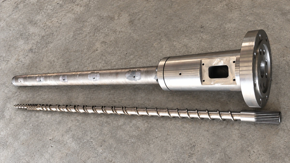
Why Your Single Screw Extruder Design Causes Extrusion Defects
Nov 13, 2026
Learn how single screw extruder design parameters—L/D ratio, compression ratio, channel depth, and mixing elements—affect melt quality, throughput, and defects.
Read Article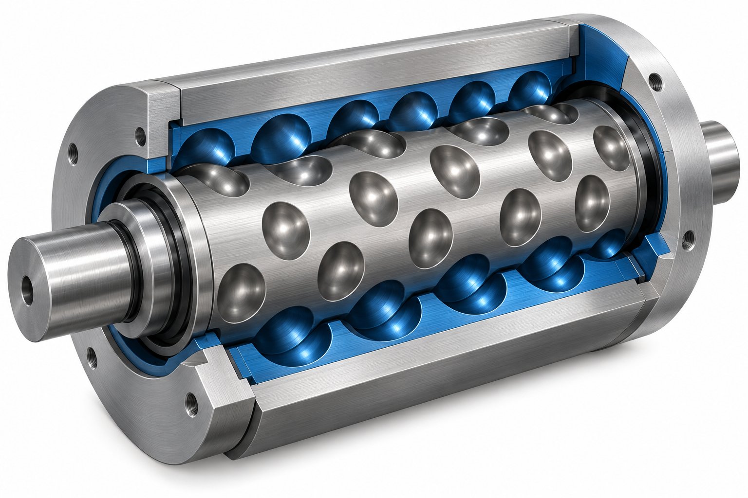
Cavity Transfer Mixer: The Blender Your Extruder Didn't Know It Needed
Nov 13, 2026
Learn how a cavity transfer mixer (CTM) upgrades single-screw extruder mixing. Covers working principles, key parameters, integration, applications, and comparisons.
Read Article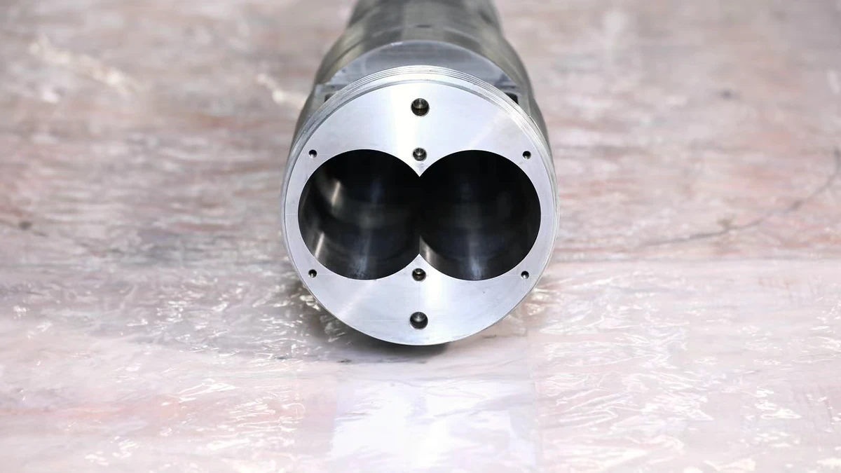
Extruder Barrel Alignment Decoded: Tolerances Most Plants Miss
Nov 13, 2026
Learn extruder barrel alignment tolerances, laser procedures, thermal offsets, and proactive schedules most plants miss — for single-screw and twin-screw lines.
Read ArticleLooking for something else?
Search by material, symptom or product and jump straight to the relevant page.
These are navigation suggestions based on keyword matching — not a quotation, not a delivery commitment, and not a substitute for engineering review. Final specification is confirmed by our engineers against your drawings and processed material.
Need help with screw barrel selection?
Share your machine model, processed material and application. Our team can help with pricing and technical support.