

What Is Melt Fracture and Why Every Extrusion Line Should Care
Imagine running your extrusion line at full capacity, only to pull a sample and find a rough, ridged, or wildly distorted surface where smooth plastic should be. That defect has a name, and it is one of the most persistent challenges in polymer processing.
Defining Melt Fracture in Practical Terms
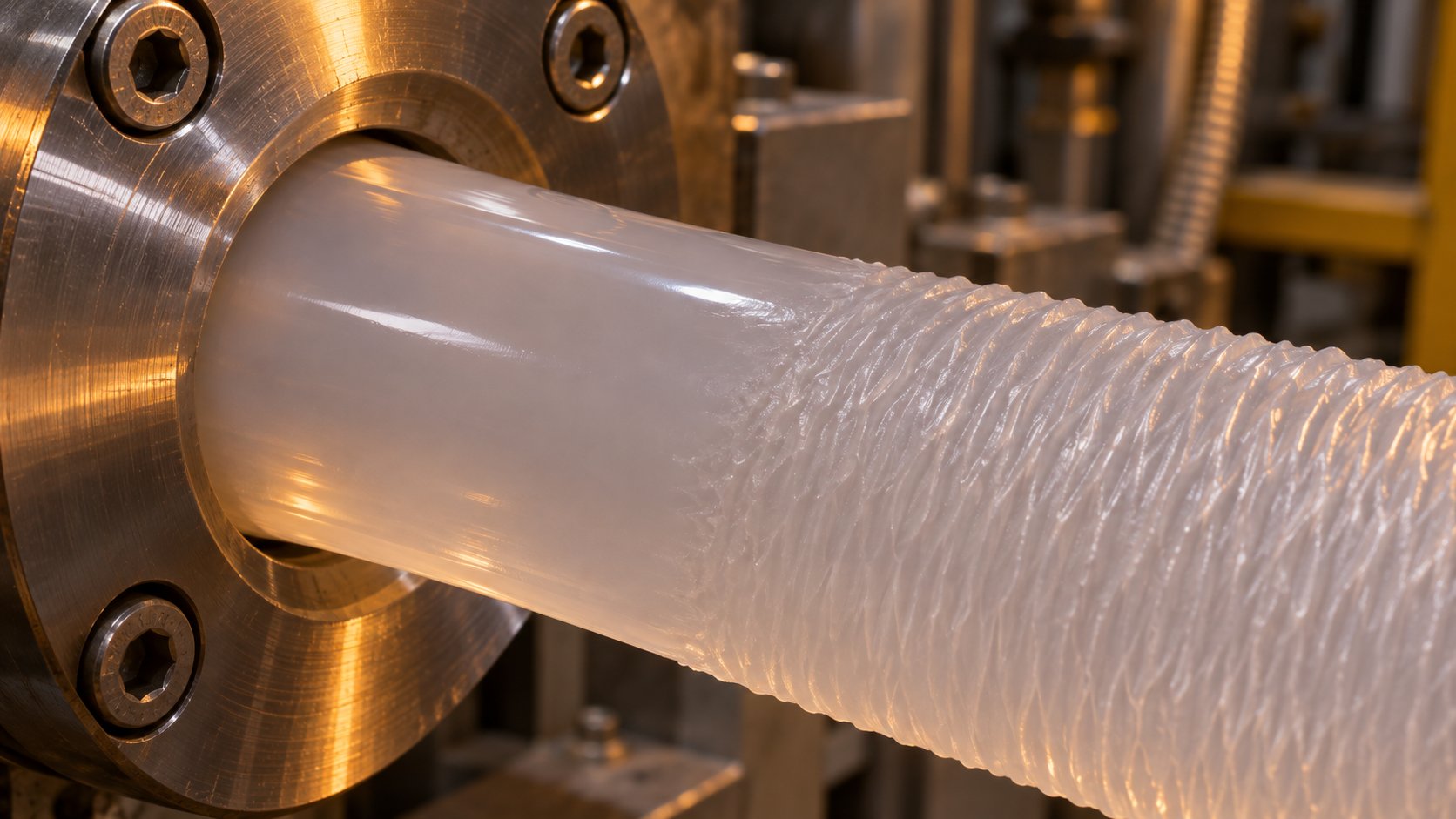
Melt fracture is the visible surface distortion or volumetric irregularity that appears on a polymer extrudate when the melt exceeds a critical wall shear stress or shear rate threshold at or near the die exit. It results from a rupture or instability in the normally smooth, laminar streamlines of the flowing polymer. As ScienceDirect notes, the transition from laminar flow to this fractured state can sometimes even be accompanied by an audible sound, and in extreme cases, discrete particles are discharged instead of a continuous strand.
Melt fracture is not a single defect but a family of flow instabilities - ranging from fine surface roughness known as sharkskin to severe helical or chaotic distortion of the entire extrudate cross-section - that occurs when a polymer melt is forced beyond its stable flow limit inside or at the exit of an extrusion die.
Here is what catches many processors off guard: this phenomenon is not confined to one resin or one process. It spans virtually every thermoplastic family, from polyethylene and polypropylene to PVC, polystyrene, and even fluoropolymers. The specific appearance varies - you might see a fine washboard texture, repeating bamboo-like ridges, a spiraling twist, or a completely chaotic surface - but the underlying trigger is always the same. The polymer melt has been pushed past the shear stress boundary where stable flow can be maintained.
Why Melt Fracture Matters on the Production Floor
Surface defects from extrusion melt fracture are far more than cosmetic nuisances. Their consequences ripple through the entire production chain in several costly ways:
- Scrap and rework: Rough or distorted extrudate that fails visual or dimensional inspection goes straight to regrind - or worse, to waste. In high-specification applications such as optical-grade films or medical tubing, even mild sharkskin can be disqualifying.
- Forced throughput reductions: The most immediate shop-floor response is to slow the line down, pulling the shear rate below the critical threshold. Production capacity drops, delivery schedules slip, and unit costs climb.
- Downstream property losses: Gross melt fracture in blown film compromises optical clarity and haze values. In barrier packaging, surface irregularities can thin or disrupt functional layers, degrading barrier performance. Dimensional inconsistency undermines sealing reliability, and mechanical weak points introduced by the distortion reduce impact and tear strength.
- Mitigation costs: Whether the fix involves fluoropolymer processing aids dosed at ppm levels, die lip polishing, surface coatings, or a full die redesign, each intervention carries material, labor, and downtime expenses.
These cost categories are why understanding the phenomenon deeply is not optional for extrusion engineers and die designers - it is an economic imperative. As processing demands push lines toward higher output rates and thinner gauges, the margin between stable flow and the onset of surface defects continues to shrink.
Who This Guide Serves
This article bridges rheological theory and shop-floor troubleshooting. It is written for process engineers diagnosing a rough extrudate at 2 a.m., die designers selecting land lengths and entry angles, quality-control teams distinguishing true melt-related defects from interfacial instabilities in coextrusion, and resin specifiers evaluating whether a new metallocene grade can run on existing equipment without processing-aid support. The scope covers extrusion processes - film, pipe, profile, and sheet - as well as blow molding and coextrusion, where melt fracture blown film defects and multi-layer flow challenges intersect.
The journey starts with learning to tell the different types of this defect apart, because each one originates in a different zone of the die and responds to a different set of corrective actions.
Three Types of Melt Fracture Every Engineer Must Distinguish
Not every rough extrudate tells the same story. A faint surface texture on a blown film sample and a wildly spiraling pipe parison may both fall under the melt fracture umbrella, yet they originate in different zones of the die, obey different mechanisms, and - critically - demand different corrective actions. Treating them as interchangeable is one of the fastest ways to waste time and money on the wrong fix.
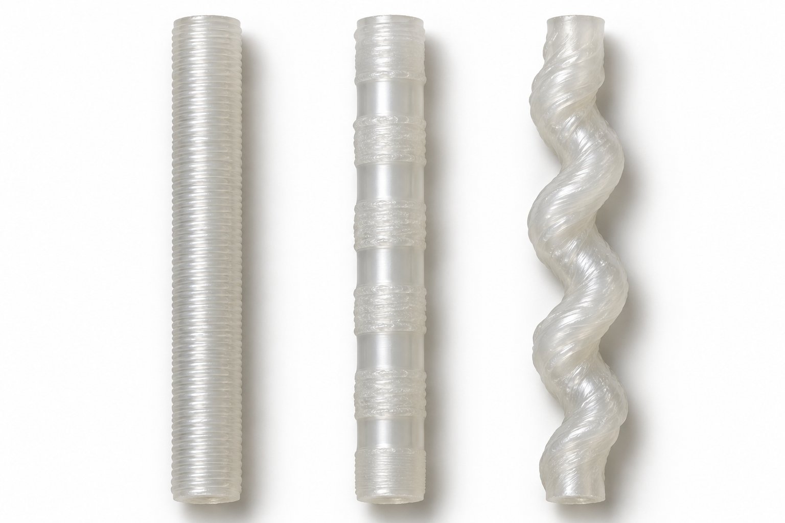
The polymer processing community recognizes three distinct types, and they tend to appear in a predictable sequence as extrusion throughput (and therefore wall shear stress) increases. Think of them as stages on a continuum: the defect starts mild and localized, then grows in severity until it consumes the entire cross-section of the extrudate.
Sharkskin - The Onset Stage
Run your finger along an extrudate that has just crossed its first critical stress threshold, and you will feel it before you see it - a fine, regular, ridge-like roughness reminiscent of, well, sharkskin. The ridges are typically short-wavelength and remarkably uniform, almost like a tiny washboard pressed into the surface.
Where does it come from? Sharkskin originates right at the die exit lip, not deep inside the die land or the entry region. As the polymer melt exits the die, the outermost layer of material - the layer that was sheared hardest against the die wall - suddenly loses its constraint. It must accelerate from near-zero velocity at the wall to the free-surface speed of the extrudate in an extremely short distance. That abrupt velocity rearrangement creates intense extensional stress at the exit corner.
At the molecular level, the prevailing explanation centers on wall slip and chain disentanglement. Polymer chains near the die wall are entangled both with each other and with chains adsorbed onto the metal surface. When the wall shear stress reaches a critical value, those entanglements can no longer hold. The surface layer periodically sticks to the die lip, stretches, snaps free, and then re-adheres - a quasi-periodic cycle that stamps those characteristic ridges into the surface. Research from Leiden University describes this as the extrudate "quasi-periodically sticking to the outlet, widening, snapping loose and narrowing."
Two important practical points about sharkskin:
- It affects only the surface. Cut the extrudate open and the bulk cross-section is undistorted. This is why it is sometimes called surface melt fracture.
- It appears at the lowest critical stress threshold of all three types - often the first warning sign that your melt fracture extrusion window is closing. For many linear polyethylenes, the onset wall shear stress can be in the range of approximately 0.1 to 0.3 MPa, as capillary rheometer studies on LLDPE have confirmed.
Sharkskin is especially familiar to anyone running melt fracture film lines with metallocene LLDPE grades. Their narrow molecular weight distribution makes them particularly prone to this defect, a topic explored in detail later in this guide.
Stick-Slip or Oscillating Melt Fracture
Push the shear rate higher past the sharkskin zone, and something dramatic happens: the extrudate starts alternating between smooth and rough sections in a repeating pattern. Some samples look almost like bamboo stalks - distinct bands of glossy surface separated by rings of distortion. This is stick-slip melt fracture, also called oscillating or spurt flow.
The mechanism is a pressure oscillation cycle driven by the interplay between melt compressibility upstream of the die and flow behavior inside the capillary. Here is the sequence:
- Stick phase: The melt adheres to the die wall under a no-slip condition. Pressure builds in the reservoir upstream as the extruder continues to pump material forward.
- Critical stress reached: Wall shear stress climbs until it triggers a sudden, catastrophic disentanglement of bulk polymer chains from those adsorbed on the wall - a cohesive failure at the interface.
- Slip phase: The melt surges forward under massive wall slip, producing a burst of smooth extrudate. Pressure drops sharply.
- Re-adhesion: As pressure falls, the stress drops below the threshold needed to maintain slip. Chains re-entangle with the wall, the no-slip condition reasserts itself, and the cycle repeats.
The result on the extrudate is unmistakable: alternating bands of rough (stick) and relatively smooth (slip) surface. Research on HDPE and LLDPE has shown that the large volume ratio between the upstream reservoir and the narrow die capillary provides enough compressible "spring" to sustain this oscillation, even though polymer melts have only modest compressibility. Studies by Hatzikiriakos and Dealy demonstrated that the shear stress becomes a double-valued function of the apparent shear rate in this regime - the rheological fingerprint of spurt flow.
The discontinuity on the flow curve - where shear stress becomes a double-valued function of shear rate - is the rheological fingerprint of stick-slip melt fracture and the key to distinguishing it from sharkskin or gross distortion.
Stick-slip instability is a volume distortion initiated inside the die capillary, not just at the exit lip. It occupies an intermediate severity level: worse than sharkskin, but the distortion still shows periodicity. In melt fracture in blown film operations, stick-slip can produce visible banding in the bubble that repeats at a regular interval tied to the oscillation frequency.
Gross Melt Fracture - Volume Distortion
Increase throughput further still, and you cross into the most damaging territory. Gross melt fracture - sometimes called volume melt fracture - involves severe, irregular distortion of the entire extrudate cross-section. Forget subtle surface ridges; imagine a helical corkscrew, a chaotic tangle, or an extrudate so violently deformed that it barely resembles the die profile it just exited.
The origin of gross melt fracture lies upstream, in the die entry or convergence zone, not at the die lip. As pressurized melt accelerates from a wide reservoir into the narrow die capillary, it experiences intense extensional (stretching) stress. When that extensional stress exceeds a critical value, the melt effectively undergoes an elastic rupture - a tensile failure of the viscoelastic fluid. A spiraling motion of the melt in the converging entry can produce helical extrudates, sometimes called "corkscrewing." At even higher throughputs, this entrance instability becomes chaotic and aperiodic, involving true rupture and yielding an extremely rough, irregular filament.
Key characteristics that set gross melt fracture apart:
- It distorts the entire volume, not just the skin.
- It originates in the die entry region, driven by extensional stress in the converging flow.
- It occurs at the highest shear-rate threshold of the three types.
- Not all polymers pass through the sharkskin and stick-slip stages first. Some can jump directly from smooth extrusion to chaotic gross distortion, as Dealy and Kim documented.
The onset of extrusion instabilities has been broadly estimated to lie between 0.1 and 2 MPa of wall shear stress across different polymers, with the specific threshold depending heavily on molecular weight, molecular weight distribution, branching architecture, and the die geometry used.
Side-by-Side Comparison of All Three Types
The table below consolidates the distinguishing features so you can quickly match what you see on your extrudate to the correct instability type - and point your corrective efforts in the right direction.
| Feature | Sharkskin | Stick-Slip (Oscillating) | Gross Melt Fracture |
|---|---|---|---|
| Visual Appearance | Fine, regular, short-wavelength ridges on surface; matte or rough texture | Alternating bands of smooth and rough surface; bamboo-like periodic pattern | Severe helical (corkscrew), wavy, or chaotic distortion of entire cross-section |
| Origin Location | Die exit lip | Die capillary wall (with upstream reservoir compressibility) | Die entry / convergence zone |
| Underlying Mechanism | Periodic stick-release at exit corner; extensional stress on surface layer; chain disentanglement at wall | Global oscillation between no-slip and wall-slip states; pressure builds during stick phase, releases during slip phase | Elastic instability / tensile failure of melt under high extensional stress in converging flow |
| Onset Severity | Lowest critical stress threshold - first to appear | Intermediate - appears between sharkskin and gross distortion zones | Highest critical stress threshold - most severe form |
| Typical Critical Stress Range | Lowest (approximately 0.1 - 0.3 MPa for many linear PEs) | Intermediate (within the multi-valued / discontinuous region of the flow curve) | Highest (can reach 0.5 - 2+ MPa depending on polymer and die geometry) |
| Cross-Section Affected | Surface only | Surface with periodic volume variation | Entire volume |
Knowing which type you are dealing with is more than academic classification - it determines whether your corrective action should focus on the die lip, the die land, the entry geometry, or the resin itself. That corrective logic, in turn, depends on understanding the rheological flow curve that underpins all three instabilities and the shear-stress thresholds specific to each polymer family.
The Flow Curve Decoded — Shear Thresholds Behind Every Defect
Every instability described in the previous section leaves a telltale signature on a single laboratory graph: the polymer flow curve. If the side-by-side comparison table tells you what you are looking at on the extrudate, the flow curve tells you why it appeared — and, more importantly, how close your current operating point is to the next threshold. You do not need a PhD in rheology to read one. You just need to know what the curve's shape is telling you.
Reading the Flow Curve for Melt Fracture Clues
Picture a graph with wall shear stress on the vertical axis and apparent shear rate on the horizontal axis, both plotted on logarithmic scales. When you run a capillary rheometer test — pushing a polymer melt through a small die at progressively higher speeds — you generate exactly this plot. Here is what the curve reveals at each stage:
- Stable power-law region (low to moderate shear rates): The curve climbs smoothly with a predictable slope. The melt flows without any instability, and the extrudate comes out glossy and defect-free. This is the safe operating zone every processor wants to stay inside.
- First critical wall shear stress — sharkskin onset: At a specific stress level, the extrudate surface begins to show fine ridges. On the flow curve itself, the change is subtle — perhaps a barely noticeable inflection — but the extrudate appearance shifts unmistakably from smooth to rough. For many linear polyethylenes, this first threshold falls in a relatively low stress range.
- The discontinuous or multi-valued region — stick-slip territory: Push harder, and the curve does something unusual: it appears to develop a negative slope or a gap. The melt can no longer maintain a single steady-state flow rate for a given applied pressure. Instead, it oscillates between two branches — one corresponding to wall adhesion and one corresponding to wall slip. This is the spurt-flow zone, and it produces those alternating smooth-rough bands on the extrudate. Capillary rheometer studies confirm that plotting pressure versus shear rate makes the onset and cessation of this instability clearly visible.
- Upper stable branch — full wall slip: At still higher rates, the melt transitions entirely to a slip-dominated flow. The curve resumes a monotonic climb, and — counterintuitively — the extrudate may become smoother again because the oscillation has ceased. However, this regime often overlaps with the onset of gross melt fracture driven by entry-zone elastic instability, so a "smooth" surface here does not guarantee a defect-free product.
The discontinuity on the flow curve — where a single applied pressure can correspond to two different flow rates — is the rheological fingerprint of stick-slip polymer melt fracture. Identifying that region on your resin's flow curve is the fastest way to map the danger zone for your process.
One critical nuance deserves emphasis: melt fracture in polymer extrusion correlates more reliably with wall shear stress than with shear rate. As Malvern Panalytical notes, this means the correlation between a laboratory rheometer and actual process conditions may not be exact if you compare only shear rates without accounting for differences in die geometry and pressure drop. Always reference stress values when translating lab data to the production floor.
Critical Shear Stress and Shear Rate Thresholds by Polymer
So what is melt fracture's trigger point for the resin on your line? The answer varies considerably from one polymer family to the next — and even between grades within the same family. Molecular weight, molecular weight distribution, branching architecture, melt temperature, and die geometry all shift the boundaries. The table below provides a practical starting framework. Where published research supplies specific values, they are included; elsewhere, the table directs you to consult your resin supplier's data sheet, because generic numbers could be misleading.
| Polymer | Approx. Critical Wall Shear Stress — Sharkskin Onset | Approx. Critical Wall Shear Stress — Gross Melt Fracture Onset | Notes |
|---|---|---|---|
| HDPE | ~0.1 – 0.3 MPa | ~0.5 – 1.0+ MPa | Strong stick-slip region; broad-MWD grades show delayed onset |
| LLDPE (Ziegler-Natta) | ~0.1 – 0.3 MPa | ~0.5 – 1.0+ MPa | Broader MWD than metallocene grades provides some resistance |
| LLDPE (Metallocene) | ~0.1 – 0.2 MPa | Consult resin data sheet | Narrow MWD makes sharkskin onset earlier and more pronounced |
| LDPE | Generally higher than linear PEs | Consult resin data sheet | Long-chain branching provides significant melt fracture resistance |
| PP | Consult resin data sheet | Consult resin data sheet | Moderate susceptibility; controlled-rheology grades may differ from reactor grades |
| PVC | Consult resin data sheet | Consult resin data sheet | External lubricant system dominates wall-slip behavior; atypical flow curve |
| PS | Consult resin data sheet | Consult resin data sheet | Amorphous; critical stress profile differs from semi-crystalline resins |
| PMMA | Consult resin data sheet | Consult resin data sheet | Amorphous; relatively high melt viscosity narrows the processing window |
| Fluoropolymers (PTFE, FEP, PFA) | Very low relative threshold | Very low relative threshold | Extremely high melt viscosity and poor wall adhesion create severe, early-onset instabilities |
A few patterns stand out. Linear polyethylenes — HDPE and LLDPE — are among the most studied systems, and their sharkskin onset tends to cluster in the 0.1 to 0.3 MPa range under standard capillary test conditions. Research by Ebrahimi et al. found that the onset of flow instabilities in LLDPE is significantly affected by both die geometry and the molecular weight characteristics of the polymer — reinforcing the point that no single universal threshold exists. Fluoropolymers sit at the opposite extreme: their combination of very high melt viscosity and poor wall adhesion means instabilities can appear at remarkably low throughputs, making them some of the most challenging materials to extrude cleanly.
Molecular Weight Distribution and Catalyst Effects
If two polyethylene grades have similar average molecular weights but different molecular weight distributions, they can behave very differently at the die lip. This is one of the most practically important — and frequently underestimated — variables in melt fracture in extrusion.
Here is the core principle: a broad molecular weight distribution (MWD) gives the polymer melt a wide spectrum of relaxation times. Short chains relax quickly and act as internal lubricants, while long chains carry the load. This broad relaxation spectrum translates into stronger shear-thinning behavior — the viscosity drops more steeply as shear rate increases — which effectively lowers the wall shear stress at any given throughput. The result? The melt reaches the critical stress threshold later, at a higher output rate. Broad-MWD resins therefore tend to resist melt fracture better and offer a wider processing window.
Contrast this with a narrow MWD, where nearly all chains have similar lengths. Their relaxation times cluster tightly, shear-thinning is less pronounced, and the wall stress climbs more steeply with increasing shear rate. The melt hits the critical threshold sooner.
This distinction maps directly onto catalyst technology. Traditional Ziegler-Natta catalysts contain multiple types of active sites, each producing chains of different lengths. The outcome, as Shamiri et al. detail, is a heterogeneous polymer with broad — sometimes even multimodal — MWD and uneven co-monomer distribution. From a melt-fracture standpoint, that breadth is an advantage.
Metallocene catalysts, by contrast, feature a single type of active site. They produce polyolefins with remarkably uniform microstructures: narrow MWD, narrow chemical composition distribution, and homogeneous co-monomer placement. These attributes are prized for mechanical properties and film clarity, but they come with a rheological trade-off. Metallocene LLDPE, for example, is notoriously prone to sharkskin because its narrow relaxation spectrum offers less built-in shear thinning. This is precisely why metallocene blown-film lines almost universally require fluoropolymer processing aids — a cost directly traceable to the catalyst's molecular fingerprint.
Long-chain branching adds yet another dimension. LDPE produced via high-pressure free-radical polymerization carries extensive long-chain branches that dramatically increase melt elasticity and strain-hardening behavior. Those branches give the melt greater resistance to the extensional stresses at the die exit, which is one reason LDPE is significantly more resistant to sharkskin than its linear cousins despite sometimes having a narrower MWD than Ziegler-Natta LLDPE. Ebrahimi et al. confirmed that molecular weight characteristics correlate well with critical conditions for the onset of flow instabilities, further underscoring the link between chain architecture and processability.
The practical takeaway? When evaluating a new resin grade — especially one synthesized with a metallocene or other single-site catalyst — do not assume it will run like the Ziegler-Natta grade it replaces. Check the MWD, request capillary rheometer flow curves from your supplier, and factor in the likely need for processing aids or die modifications before the material ever reaches your hopper.
These molecular-level differences also explain why die geometry plays such a powerful role in tipping the balance toward or away from stable flow — a relationship explored in the next section.
Die Design Parameters That Control Melt Fracture Onset
Molecular architecture sets the stage, but the die is where the drama unfolds. Two resins with identical MWD and melt index can behave very differently if one passes through a well-optimized die and the other fights its way through a poorly dimensioned channel. Understanding how specific geometric features push the melt toward — or safely away from — its critical stress threshold gives engineers a set of levers that work independently of resin chemistry. These levers are often the fastest and most cost-effective way to eliminate melt fracture on an existing line.
Land Length, L/D Ratio, and Entry Angle
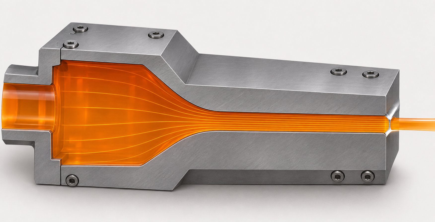
The die land is the final straight section of the flow channel just before the exit, where the cross-section remains constant. Its length relative to its gap — the L/D ratio — is one of the most influential variables in defining melt fracture onset.
A longer land means the polymer melt spends more time under high wall shear stress. If that stress already sits near the critical threshold, additional residence time can push the surface layer into the sharkskin regime or intensify stick-slip oscillations. Yet going too short introduces a different problem: the melt entering the land carries elastic strain energy stored during convergence upstream. A very short land may not provide enough distance for those elastic disturbances to relax before the melt reaches the exit lip, which can amplify both die swell and melt fracture simultaneously. As extrusion consultant Chris Rauwendaal notes, a common starting guideline is to set land length at roughly 10 times the land clearance (gap), though the optimum depends on the polymer's rheology and the shear rate in play.
The entry angle — the taper that funnels melt from the wider upstream channel into the narrow land — plays an equally critical role, particularly for gross melt fracture. A steep convergence angle forces the melt to accelerate sharply, generating high extensional strain energy in a short distance. That extensional stress is the trigger for the elastic entry instabilities that produce helical or chaotic volume distortion. Moderate taper angles spread the acceleration over a longer path, reducing peak extensional stress and delaying gross distortion onset. The general design principle, reinforced by die design best practices, is to avoid abrupt changes in flow channel geometry and to favor small approach angles.
Imagine squeezing toothpaste through a funnel: a gentle taper lets it flow smoothly, but jam it into a sharp constriction and the stream tears apart. The polymer melt behaves analogously — and that tearing is exactly what gross melt fracture looks like.
Die Lip Geometry and Surface Finish
If land length and entry angle govern what happens inside the die, lip geometry governs what happens at the critical instant the melt leaves it. A sharp, square-edged die exit concentrates extensional stress right at the corner where the surface layer must accelerate from near-zero wall velocity to free-stream speed. That stress concentration is the primary driver of sharkskin. Introducing a small chamfer or radius at the exit lip spreads the acceleration zone, reduces peak extensional stress, and can measurably delay onset.
Surface finish matters just as much. A rough die wall increases the effective friction coefficient between polymer and metal, raising wall shear stress at any given throughput. Polishing the land and lip surfaces to a mirror finish is often the simplest first intervention. Beyond mechanical polishing, several surface treatment technologies can further reduce friction and help processors define melt fracture boundaries more favorably:
- Chrome plating: The industry standard for corrosion resistance and moderate friction reduction. Hard chrome provides a smooth, durable surface but offers limited improvement in wall-slip promotion compared to more advanced coatings.
- Diamond-like carbon (DLC) coatings: These amorphous carbon films combine high hardness with low friction and good resistance to adhesive wear. DLC can reduce breakaway forces and suppress polymer adhesion at the die wall, making it a strong option for demanding extrusion applications — though coating architecture must be matched to the substrate and operating temperature, as performance varies significantly between DLC variants.
- PTFE (fluoropolymer) die coatings: Applied to the land and lip surfaces, these coatings dramatically lower the surface energy and friction coefficient, promoting wall slip. They are particularly effective for resins prone to sharkskin but may wear faster than metallic or ceramic alternatives under abrasive filled compounds.
- Nickel-PTFE composite plating: Combines the mechanical durability of nickel with the low friction of embedded PTFE particles. A practical middle ground between pure chrome and pure fluoropolymer coatings.
- Ceramic and nitride coatings (e.g., TiN, CrN): Primarily chosen for wear resistance in filled-resin applications, these coatings also offer moderately low friction and excellent hardness, helping maintain a smooth surface finish over extended production campaigns.
The right choice depends on the resin, the operating temperature, the expected production volume, and whether the dominant concern is sharkskin suppression, wear resistance, or both. In high-output blown film lines running metallocene LLDPE — a scenario familiar to any china melt fracture blown film operation pushing capacity limits — combining a DLC- or PTFE-coated die lip with fluoropolymer processing aids often delivers the widest stable operating window.
Practical Die Modification Checklist
When melt fracture appears on your extrudate, a systematic die review prevents wasted effort. Rauwendaal emphasizes that streamlining the die flow channel is always a sound strategy, but a structured inspection sequence ensures you address the likeliest causes first and avoid unnecessary rework. Follow this stepwise approach:
- Inspect the die lip condition: Look for nicks, burrs, polymer buildup (die drool), or erosion at the exit edge. Even minor damage concentrates extensional stress and can trigger sharkskin on a line that previously ran clean.
- Measure land length against resin recommendations: Compare the actual L/D ratio to the resin supplier's processing guide. If the land is excessively long for a shear-sensitive grade, reducing it — or widening the gap — lowers wall shear stress.
- Evaluate the entry angle: A steep convergence zone is a prime suspect when gross melt fracture (helical or chaotic distortion) is the dominant defect. If redesign is impractical, inserting a tapered flow insert or trumpet-shaped transition can reduce peak extensional stress.
- Check surface finish quality: Run a fingernail or profilometer across the land. Scratches, corrosion pitting, or worn plating increase wall friction. Polish or re-plate as needed.
- Consider a low-friction coating or surface upgrade: If polishing alone is insufficient, evaluate DLC, PTFE, or nickel-PTFE coatings based on your resin and temperature profile.
- Verify thermal uniformity across the die: Uneven die temperatures create viscosity gradients that cause localized zones to exceed the critical stress while the rest of the die operates safely. Check heater bands and thermocouple placement. Die-land heaters, as Rauwendaal notes, can reduce shear stress enough to suppress defects while even allowing throughput increases of up to 20%.
- Document findings and changes: Record every measurement and modification. The next time a similar resin or product runs on this die, the documentation shortens troubleshooting from hours to minutes.
Die geometry and surface condition are powerful tools, but they operate on only one half of the equation — the hardware side. The polymer flowing through that die carries its own molecular fingerprint, and different resin families respond to these geometric levers in strikingly different ways. Understanding those polymer-specific behaviors is what turns a generic checklist into a targeted solution.
Polymer-by-Polymer Melt Fracture Behavior and Mitigation
A die checklist and a flow-curve tutorial are valuable, but they only become actionable when you know how your specific resin behaves under stress. A metallocene LLDPE and a long-chain-branched LDPE might both be "polyethylene," yet their melt fracture profiles could hardly be more different. The same is true when you compare polypropylene to PVC, or either of them to a fluoropolymer like FEP. Each polymer family arrives at the die with a unique combination of molecular architecture, melt elasticity, and wall-adhesion characteristics that dictates which type of instability appears first, at what severity, and which corrective lever works best.
This section walks through the major thermoplastic families one by one, giving you a consolidated reference you can carry to the production floor.
Polyethylenes - HDPE, LLDPE, LDPE, and Metallocene Grades
Polyethylenes dominate extrusion volumes worldwide, and they also dominate the melt fracture literature for good reason: linear PE grades are among the most susceptible resins to surface and volumetric instabilities. Yet not all polyethylenes misbehave equally. The differences come down to chain architecture.
LDPE (low-density polyethylene) is the most forgiving member of the family. Produced via high-pressure free-radical polymerization, LDPE carries extensive long-chain branches that give its melt pronounced strain-hardening behavior. When the surface layer stretches at the die exit, those branches resist the extensional deformation rather than tearing apart. The result is a significantly higher threshold before sharkskin appears compared to its linear cousins. LDPE also exhibits stronger shear thinning, which keeps wall shear stress lower at any given throughput. If you have ever noticed that an older LDPE blown-film line runs trouble-free at speeds that cripple a newer LLDPE line, this molecular advantage is a big part of the explanation.
HDPE (high-density polyethylene) is linear with minimal branching. Its melt fracture behavior is well documented: sharkskin typically appears in the 0.1 to 0.3 MPa wall shear stress range, followed by a pronounced stick-slip regime with clear pressure oscillations, and then gross distortion at higher rates. Broad-MWD HDPE grades produced with Ziegler-Natta catalysts benefit from their wide relaxation-time spectrum - the short chains lubricate internally while the long chains carry the load - which delays onset relative to narrower grades.
LLDPE (linear low-density polyethylene) behaves similarly to HDPE in its susceptibility pattern, but there is a critical split within the LLDPE family tied to catalyst technology. Conventional Ziegler-Natta LLDPE has a relatively broad MWD and heterogeneous co-monomer distribution. That breadth provides some built-in resistance. Metallocene LLDPE, however, tells a different story entirely.
Metallocene catalysts produce chains of remarkably uniform length and composition - excellent for film clarity, dart impact, and seal strength, but problematic for processability. The narrow MWD means less shear thinning and a steeper stress buildup as shear rate increases. Sharkskin onset arrives earlier and is more pronounced. Research from the University of British Columbia confirms that metallocene LLDPE (m-LLDPE) requires processing aids to eliminate these instabilities, with both PPA concentration and temperature playing key roles in delaying the critical threshold. This is why virtually every metallocene blown-film line runs with fluoropolymer processing aids as standard practice - a direct operational cost stemming from the resin's molecular fingerprint.
Polypropylene, PVC, and Polystyrene
Polypropylene (PP) occupies a middle ground. Its semi-crystalline nature and relatively high melt elasticity make it moderately susceptible to extrusion melt fracture, though typically less so than linear polyethylenes at comparable shear rates. Controlled-rheology (CR) PP grades - peroxide-visbroken to narrow the MWD for fiber or nonwoven applications - can behave differently from reactor-grade PP, sometimes showing earlier sharkskin onset due to the narrower relaxation spectrum. Reactor grades with broader MWD generally offer a wider stable processing window. Entry-zone instabilities can produce gross distortion in PP at high throughputs, particularly in profile and sheet extrusion where die geometries impose steep convergence angles.
PVC is the outlier. Unlike polyolefins, PVC does not melt in the conventional sense; it fuses into a gel-like state while retaining some primary particle structure. Wall-slip behavior in PVC extrusion is controlled almost entirely by the external lubricant package - typically stearates and waxes - rather than by the polymer's intrinsic rheology. As Rollepaal's PVC processing guidance explains, sufficient lubrication creates adequate wall slip between the PVC melt and the metal surfaces of the extruder and die, preventing excessive local friction and heat buildup that can cause burning and degradation. Practice shows that shifting the lubricant balance toward higher-melting waxes improves processing reliability at elevated output rates. Get the lubricant system wrong, and you will see surface defects that resemble classic sharkskin - but the fix lies in reformulating the compound, not in changing the die lip or adding a fluoropolymer PPA.
Polystyrene (PS) and PMMA are amorphous thermoplastics with their own distinct critical-stress profiles. PS generally has a moderate processing window and can develop sharkskin at high shear rates, though its tendency is less dramatic than that of linear polyethylenes. PMMA, with its relatively high melt viscosity and stiff backbone, can present a narrower safe operating envelope. Both resins respond well to die-geometry optimization and temperature adjustments, since their amorphous structure eliminates the crystallization-related complications that affect semi-crystalline polymers. For these materials, ensuring a polished die surface and moderate entry angles often provides sufficient margin against surface instabilities.
Fluoropolymers - The Extreme Case
If metallocene LLDPE is the resin that keeps blown-film operators reaching for processing aids, fluoropolymers are the family that keeps rheologists up at night. Materials like PTFE, FEP, and PFA present some of the most severe melt fracture challenges in all of polymer processing - and there is no easy additive shortcut, because the base resin itself is the fluoropolymer.
Why are they so difficult? Three factors converge simultaneously:
- Extremely high melt viscosity: Fluoropolymers require elevated processing temperatures and still deliver viscosities that push wall shear stress toward critical thresholds even at modest throughput rates. As fluoropolymer extrusion guides note, precise temperature control and specialized equipment are essential because even small deviations can trigger instabilities or thermal degradation.
- Poor wall adhesion: The very property that makes fluoropolymers non-stick - their extremely low surface energy - works against stable extrusion. The melt refuses to adhere uniformly to the die wall, creating erratic slip conditions that can produce both sharkskin and stick-slip oscillations at unusually low shear rates.
- Narrow processing windows: The gap between the temperature needed for adequate flow and the ceiling imposed by thermal degradation is tight. Raising melt temperature to reduce viscosity quickly runs into decomposition risks, especially with PTFE, which can release hazardous fumes above its degradation threshold.
The standard playbook of adding a fluoropolymer PPA to promote wall slip obviously does not apply when the problematic resin is already a fluoropolymer. Instead, mitigation relies heavily on die design refinement - optimized land lengths, gentle entry tapers, and ultra-polished or specially coated die surfaces - combined with meticulous temperature profiling and reduced line speeds. Processors report that lowering shear rates, refining temperature distribution, and selecting appropriate fluoropolymer grades for the target application are the primary control strategies. Maximum deformation before melt fracture occurs is reached much sooner than with most other thermoplastics, leaving very little room for error.
Polymer Family Summary Table
The table below consolidates each family's typical behavior, giving you a quick-reference guide for identifying the likeliest instability type and the first mitigation lever to pull.
| Polymer Family | First Instability Type Encountered | Relative Severity | Primary Mitigation Strategy |
|---|---|---|---|
| LDPE | Sharkskin (at relatively high shear rates) | Low - long-chain branching provides strong resistance | Die geometry optimization; rarely needs PPA |
| HDPE | Sharkskin, followed by pronounced stick-slip | Moderate to high | Fluoropolymer PPA; broad-MWD grade selection; die lip polishing |
| LLDPE (Ziegler-Natta) | Sharkskin | Moderate | Fluoropolymer PPA; die surface treatment |
| LLDPE (Metallocene) | Sharkskin (early onset, very pronounced) | High | Fluoropolymer PPA (nearly always required); die coating; consider blending with LDPE |
| PP | Sharkskin or gross distortion depending on die geometry | Moderate | Die entry angle optimization; temperature adjustment; broad-MWD reactor grades |
| PVC | Surface roughness resembling sharkskin | Low to moderate (lubricant-dependent) | External lubricant package reformulation (stearates, waxes); die temperature control |
| PS | Sharkskin at high shear rates | Low to moderate | Die surface polish; moderate entry angle; temperature increase |
| PMMA | Sharkskin | Moderate (narrow processing window) | Die geometry and surface finish; careful temperature profiling |
| Fluoropolymers (PTFE, FEP, PFA) | Sharkskin and stick-slip at very low throughputs | Very high - most challenging family | Die design refinement; ultra-polished surfaces; reduced shear rates; precise thermal control |
A pattern emerges from this comparison: the more linear and uniform the polymer chain, the more vulnerable it is to surface instabilities, while long-chain branching and broad MWD act as built-in buffers. External factors - lubricant packages for PVC, processing aids for metallocene PE, die engineering for fluoropolymers - fill the gap where molecular architecture alone cannot provide enough margin.
Knowing your resin's personality is essential, but the picture is incomplete without understanding how specific process contexts amplify or alter these behaviors. Blown film, blow molding, and coextrusion each impose their own shear-rate demands and diagnostic complications - particularly the critical distinction between a true surface defect and an interfacial instability hiding between coextruded layers.
Application-Specific Challenges from Blown Film to Coextrusion
Resin personality matters, but context matters just as much. A metallocene LLDPE that runs cleanly on a cast-film line at moderate output may produce sharkskin the moment it enters a thin-gauge blown-film die operating at higher shear rates. A blow-molded HDPE drum that looks flawless at one parison weight can develop string-like surface defects when the wall thickness changes. And in coextrusion, the problem multiplies: you might be chasing what looks like a surface defect when the real culprit is buried between layers. Each process imposes its own shear-rate demands, cooling dynamics, and diagnostic complications that reshape how melt fracture shows up - and how you fix it.
Melt Fracture in Blown Film and Blow Molding
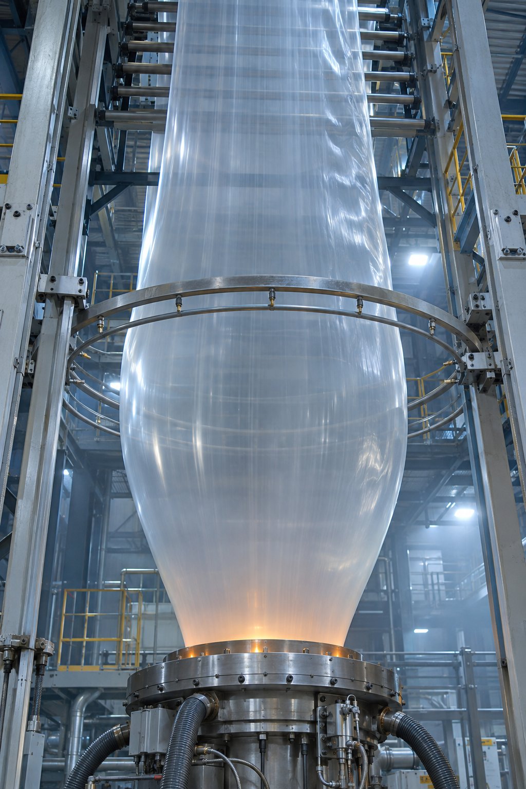
Blown film extrusion is arguably the process most frequently plagued by surface instabilities, and the reason is straightforward: thin-gauge film requires pushing the polymer through a narrow die gap at high throughput, which drives wall shear stress toward the critical threshold faster than almost any other extrusion geometry. When you are producing film at sub-mil thicknesses through a die gap of 80 to 100 mils, the draw ratio between die exit and final gauge is enormous. Any surface roughness stamped into the extrudate at the die lip gets stretched and locked into the finished film, where it scatters light and raises haze values.
Modern production trends make the problem worse. Line-speed increases driven by competitive pressure and capacity optimization push more blown-film operations closer to - or past - the onset boundary. You will notice this especially on lines running metallocene LLDPE, where the narrow molecular weight distribution leaves almost no margin between the maximum draw ratio before melt fracture and the target operating speed. As Plastics Technology reports, melt fracture in blown film can manifest as reduced surface gloss even when the roughness is not visible to the naked eye, while more severe cases produce clearly visible transverse-direction zigzag lines on the bubble.
Two distinct mechanisms can be at work simultaneously on a blown-film line:
- Pressure pulsation (stick-slip): When the melt alternates between adhering to and slipping from die surfaces, the resulting pressure oscillations ripple through the extrudate much like earthquake tremors radiating from a fault line. These pulsations produce banding patterns on the film surface.
- Skin rupture: The newly emerged film swells as it exits the die and is pulled upward while simultaneously being blasted with cooling air. If stretching and cooling happen too fast, micro-tears form on the surface - typically the outside surface, though intense internal bubble cooling (IBC) air can occasionally cause it on the inside as well.
Blow molding faces an analogous challenge during parison formation. The parison - the tubular melt preform that will be inflated into the final part - exits the die head under significant shear stress, especially for large-part applications like drums and industrial containers. Research by Inn et al. at Chevron Phillips documented a distinctive form they called "worm melt fracture" in polyethylene blow molding of large drums: string-like defects of various shapes and sizes appearing on the extrudate surface at high shear rates after the stick-slip transition. Their study found that broader MWD PE resins actually exhibited a greater degree of these string-like defects, which they attributed to a weaker internal melt structure that allows cohesive failure at an internal slip surface - a mechanism tied directly to melt fracture and cohesive forces in polymer melts. The string-like material, they hypothesized, originates from the cohesive slip layer emerging from the die attached to the extrudate surface, linked to die build-up at high shear rates.
For both blown film and blow molding, the most common operator response is to reduce output - effective but economically painful. Better alternatives include adjusting the extruder temperature profile to raise melt temperature, using finer-mesh screen packs to increase recirculation and shear heating, widening the die gap (with the understanding that this limits thin-film capability), or adding fluoropolymer processing aids. As industry practice shows, processing aids coat the metal die surfaces and reduce the coefficient of friction, but the coating distributes unevenly inside spiral-mandrel dies because shear stress varies - lower inside the spirals and higher near lands and lips. This uneven coating can alter flow patterns and sometimes worsen transverse-direction gauge variation, so careful dosing is essential.
Coextrusion - When Melt Fracture Meets Interfacial Instability
Coextrusion adds a layer of diagnostic complexity that trips up even experienced processors. Imagine inspecting a multilayer blown film and finding haze. Your instinct says melt fracture - but what if the roughness is not on the surface at all? What if it is hiding between layers, at the interface where two different polymers meet inside the die?
This is the critical distinction between true melt fracture and interfacial instability, and confusing the two leads to corrective efforts that waste time, money, and material. Applying a processing aid will not fix a viscosity-ratio-driven wave between layers. Changing die lip geometry will not resolve an encapsulation problem originating deep inside the feedblock.
A practical diagnostic test can separate them quickly: immerse a film sample in a glass of water and weigh it down with a paper clip. Surface roughness from melt fracture disappears optically when water fills the surface irregularities - the paper clip beneath looks sharp and clear. Interfacial instability lives inside the film structure, so water cannot reach it. The bumpy interface remains, and the paper clip viewed through the film appears blurry.
The table below lays out the key diagnostic differences side by side so you can pinpoint the root cause before committing to a fix.
| Diagnostic Factor | Melt Fracture | Interfacial Instability |
|---|---|---|
| Defect Location | External surface of the extrudate | Internal interface between adjacent layers |
| Visual Signature | Surface roughness, matte haze, or visible transverse-direction zigzag lines; disappears when immersed in water | Short-wave (uniform internal haze or visible waves) or long-wave (clearly defined TD striations); persists when immersed in water |
| Root Cause | Excessive wall shear stress exceeding the polymer's critical threshold at or near the die exit | Viscosity and/or elasticity mismatch between adjacent layers; thin-layer acceleration exceeding ~300% at the merge point (short wave); large viscosity differences causing encapsulation (long wave) |
| Die Zone of Origin | Die lip and land (sharkskin, stick-slip) or die entry/convergence zone (gross distortion) | Combining adapter, feedblock, or internal merge zone where layers join |
| Corrective Approach | Fluoropolymer PPA; die lip polishing or coating; die gap widening; melt temperature increase; output reduction | Match viscosities of adjacent layers (adjust extruder temperature profiles to equalize backpressure); change layer-thickness ratio so the interface moves toward the center of the flow channel; modify die merge-zone geometry (smaller merge angles, wider post-merge passages) |
A few points deserve special emphasis. Short-wave interfacial instability occurs when two layers merge inside the die and the thinner layer accelerates excessively - beyond roughly 300%, which exceeds the critical shear stress of most polymers at the interface. Long-wave instability, by contrast, results from large viscosity differences: the more viscous layer chokes off and encapsulates the less viscous one, which then builds pressure until it squirts back into the melt stream in a periodic cycle. Both forms can be managed by equalizing backpressures between extruders - raising temperature or adding finer screen packs on the higher-viscosity side - but neither responds to the die-lip modifications or processing aids that fix true surface defects.
Misdiagnosis is the most expensive mistake you can make in coextrusion troubleshooting. The water-immersion test takes thirty seconds and can save days of misdirected effort.
Downstream Impact on Product Performance
Whether the defect originates at the die lip or between coextruded layers, the consequences ripple through every performance attribute your customer cares about. Understanding these downstream impacts is what justifies the engineering effort and cost of elimination.
- Optical clarity and gloss: Even mild sharkskin scatters transmitted and reflected light, increasing haze and reducing gloss. In packaging films where shelf appeal depends on transparency, this alone can disqualify a product. The effect is compounded in melt fracture and inkjetting applications where surface roughness degrades print quality and ink adhesion.
- Barrier properties: In multilayer barrier packaging, surface irregularities can locally thin the functional barrier layer - an EVOH or nylon tie layer, for example - creating weak spots where oxygen or moisture transmission rates spike. The package still looks intact, but its shelf-life protection is compromised.
- Mechanical strength: Gross distortion introduces orientation irregularities and stress concentrators into the extrudate. Impact resistance, tear strength, and elongation at break all suffer. In blow-molded containers, surface defects act as crack initiation sites under drop-impact or internal-pressure loading.
- Dimensional consistency: Stick-slip oscillations produce periodic thickness variations that make it impossible to hold tight gauge tolerances. For pipe and profile extrusion, this translates to out-of-spec wall thickness; for film, it means weight variation per unit area and inconsistent seal-bar performance.
These are not abstract quality metrics - they translate directly into customer rejections, warranty claims, and lost business. A blown-film line producing packaging with borderline haze values may ship product that passes a generous specification today but fails after a customer tightens their requirements tomorrow. Eliminating surface and interfacial defects at the source is always more cost-effective than managing them downstream through sorting, regrading, or over-engineering the specification.
Recognizing the defect type and understanding its process-specific context are essential diagnostic steps. The next question is equally practical: what chemical and thermal tools can you deploy to push the onset threshold further away from your operating point, and how do you choose the right one for your resin and process?
Processing Aids and Temperature Strategies to Reduce Melt Fracture
You have identified the defect type, confirmed it is genuine surface instability rather than an interfacial wave, and reviewed your die geometry. The problem persists. What now? This is where chemical and thermal mitigation tools enter the picture — additives and process adjustments designed to shift the critical stress threshold upward so your operating point falls safely back inside the stable flow envelope. The options range from fluoropolymer processing aids dosed at parts-per-million levels to temperature profile tweaks that cost nothing but carry their own risks. Choosing the right tool — and understanding its mechanism well enough to avoid wasted trials — separates a quick fix from weeks of frustration.
Fluoropolymer Processing Aids — Mechanism and Loading
Fluoropolymer-based polymer processing aids (PPAs) have been the workhorse solution for melt fracture elimination in polyolefin extrusion for decades. If you run blown film with metallocene LLDPE, chances are high that a fluoropolymer PPA is already part of your formulation. But how does a trace additive measured in ppm actually suppress a flow instability driven by fundamental polymer physics?
The mechanism is elegantly simple — and entirely surface-based. Fluoropolymer PPAs, typically built on fluoroelastomer (FKM) or polyvinylidene fluoride (PVDF) chemistries, are immiscible with the polyolefin host resin at processing temperature. During extrusion, the fluoropolymer phase migrates to the die wall and deposits a thin, persistent coating on internal die surfaces. This coating dramatically lowers the friction between the flowing polyolefin melt and the metal wall, promoting wall slip. With slip established, the wall shear stress at any given throughput drops below the critical threshold — and sharkskin disappears.
A few practical details matter enormously on the production floor:
- Induction period: The die coating does not form instantly. Fluoropolymer PPAs require a conditioning period — often several minutes to tens of minutes — before the wall coating fully establishes and the extrudate surface clears. Research comparing PPA chemistries found that PEG-based alternatives decrease die pressure immediately from startup, while fluoropolymer PPAs require an induction time of approximately six minutes before affecting die pressure. This means you will not see results the moment you flip on the masterbatch feeder — patience and a well-planned startup protocol are essential.
- Loading levels: Active PPA concentration in the final extruded product is very low, typically 50 to 500 ppm. The additive is supplied as a masterbatch — fluoropolymer dispersed in a polyethylene carrier at 1 to 3% loading — for precise gravimetric dosing at the extruder throat. At these concentrations, bulk mechanical properties of the finished product remain unaffected; the PPA's action is confined entirely to the die-wall interface.
- Droplet size matters: Contrary to the intuitive assumption that finer dispersion is always better, coating kinetics research has shown that larger fluoropolymer droplets can be superior in practice. The PPA accumulates at the die entrance and flows toward the exit, and the droplet size distribution directly determines how quickly the coating establishes and how reliably it eliminates surface defects at low use levels.
- Defect specificity: Fluoropolymer PPAs are most effective against sharkskin — the exit-lip instability driven by wall adhesion. They have a meaningful but more limited impact on stick-slip, and they generally cannot eliminate gross melt fracture on their own because that defect originates upstream in the convergence zone, not at the die wall.
One significant caveat deserves attention: regulatory pressure on fluoropolymer-based PPAs is intensifying. The EU PFAS restriction proposal submitted to ECHA in 2023 covers fluoropolymers used as processing aids, and the PPWR regulation bans PFAS in food-contact packaging from August 2026. Combined with 3M's exit from fluoropolymer manufacturing, these developments are creating a hard timeline for many melt fracture blown film factories and melt fracture blown film manufacturers to qualify non-fluorinated alternatives — a transition that is technically challenging and already well underway.
Boron Nitride, Silicone, and Stearate-Based Lubricants
Fluoropolymer PPAs are effective, but they are not the only option — and for some resins and regulatory environments, they are not even an available one. Several alternative additive families address surface instabilities through different mechanisms, each with its own strengths and limitations.
- Hexagonal boron nitride (hBN): This is the most technically distinctive non-fluorinated processing aid. Research published in Rheologica Acta (Kazatchkov et al., 2000) demonstrated that boron nitride can eliminate gross melt fracture in polyolefin extrusion — a capability previously associated almost exclusively with fluoroelastomers. The mechanism involves platelet-shaped BN particles depositing on the die surface, reducing wall shear stress. BN is less effective than fluoropolymers against sharkskin alone, but combinations of BN with fluoroelastomers have shown synergistic performance — the fluoropolymer handles the exit-lip instability while BN addresses the upstream elastic distortion. Saint-Gobain's hBN powders hold FDA food-contact approval, making them viable for packaging applications. Limitation: BN alone may not fully eliminate sharkskin in highly susceptible resins like metallocene LLDPE, and the optimum loading must be determined experimentally for each resin system.
- Silicone-based PPAs: Modified copolysiloxane structures operate on a low-surface-energy principle similar to fluoropolymers — they reduce adhesion at the die wall and promote slip. Commercial offerings such as Dow's DOWSIL 5-1050 PPA have demonstrated reduced melt fracture and haze in blown film, along with decreased die lip buildup, and comply with EU food-contact regulations. These additives combine the inherently low surface energy of silicone with polar groups engineered to accelerate migration to metal die surfaces, establishing the slip-promoting coating more quickly than standard silicone oils. Limitation: performance data on stick-slip and gross distortion are less extensive than for fluoropolymers, and compatibility testing with specific resin formulations is essential — interaction effects between silicone PPAs and other additives (antiblocks, slip agents) can produce unexpected results.
- Stearate and wax-based lubricants: These external lubricants are the primary wall-slip control mechanism in PVC extrusion, where fluoropolymer PPAs are not standard practice. Calcium stearate, zinc stearate, and paraffin or oxidized polyethylene waxes create a lubricating layer between the PVC melt and the die surface, preventing the excessive friction that causes surface roughness. In polyolefin systems, stearates play a secondary role — they are sometimes used as co-additives to complement a primary PPA. Limitation: stearates can interfere with heat-seal properties and printability in film applications, and excessive loading may cause plate-out on downstream equipment.
- Polyamide-polyether block copolymers: An emerging class described in recent patent literature (EP4431563A1, WO2023241955A1), these thermoplastic elastomers derive their surface activity from an amphiphilic block structure rather than fluorine chemistry. Early commercial versions have shown promise in blown-film applications where sharkskin is the primary concern. Limitation: the technology is newer, and long-term die-buildup and multi-week production stability data are still being accumulated across the industry.
Choosing among these options is not a one-size-fits-all decision. For a melt fracture blow molding operation running HDPE drums, boron nitride's ability to address gross distortion may be more valuable than a fluoropolymer PPA optimized for sharkskin. For a melt fracture blown film factory navigating PFAS phase-outs, silicone or polyamide-polyether alternatives may be the only regulatory-compliant path forward. In every case, qualification must extend beyond initial melt fracture elimination to include die-buildup evaluation over sustained production runs — an additive that clears the surface but deposits material at the die lip simply trades one problem for another.
Temperature Adjustments — When Raising Melt Temperature Helps and When It Hurts
Imagine you have no processing aid on hand, the die geometry cannot be changed today, and the line is producing unacceptable surface roughness right now. The temptation is immediate: raise the melt temperature. It works — up to a point — but the physics underneath are worth understanding before you reach for the controller.
The interaction is straightforward in principle. Higher melt temperature lowers polymer viscosity. Lower viscosity means lower wall shear stress at any given throughput. Lower wall shear stress means you are further from the critical threshold. Research from the University of British Columbia confirmed this directly: increasing temperature helped eliminate melt fracture in metallocene LLDPE extrusion by shifting the critical shear rate boundary upward, effectively widening the stable processing window.
So why not simply crank up the temperature and be done with it? Because several ceilings close in simultaneously:
- Thermal degradation: Every polymer has a degradation threshold above which chain scission, crosslinking, discoloration, or off-gassing begins. Heat-sensitive resins like PVC and certain engineering thermoplastics have narrow safe ranges, and even polyolefins will yellow, lose molecular weight, or generate gels if held too long at elevated temperatures.
- Die drool: Higher melt temperatures reduce viscosity but can also increase the tendency for low-molecular-weight fractions, waxes, or degradation products to accumulate at the die lip — the phenomenon known as die drool or die buildup. You may eliminate sharkskin only to trigger a different surface defect from drool streaking.
- Narrowed processing window: Raising temperature to fix a surface defect consumes thermal headroom that you might need later for other adjustments. If a downstream issue requires faster cooling or a resin lot arrives with slightly different rheology, you have already used your temperature margin.
- Energy cost and cooling load: Higher melt temperatures mean more energy input and — critically for blown film and blow molding — more cooling capacity required to solidify the product. On lines already limited by cooling, the throughput gain from eliminating melt fracture may be offset by the throughput loss from slower cooling.
Temperature is a blunt tool: it works quickly, costs nothing in materials, but burns through processing headroom. Use it after die-geometry corrections and processing-aid options have been evaluated — not as the first resort.
A practical approach is to use small, deliberate temperature increments — 5 to 10 degrees at a time — while monitoring both the extrudate surface and the die lip for drool formation. Document the temperature at which the defect disappears and the temperature at which side effects begin. That range defines your thermal operating margin for the specific resin-die combination in play.
Chemical aids and temperature adjustments are powerful tools, but they act on the melt at the die. What if the melt arriving at the die is already compromised — thermally inconsistent, partially under-plasticized, or carrying viscosity gradients from worn upstream equipment? That upstream contribution is an often-overlooked factor that can make every die-side and additive-based fix less effective than it should be.
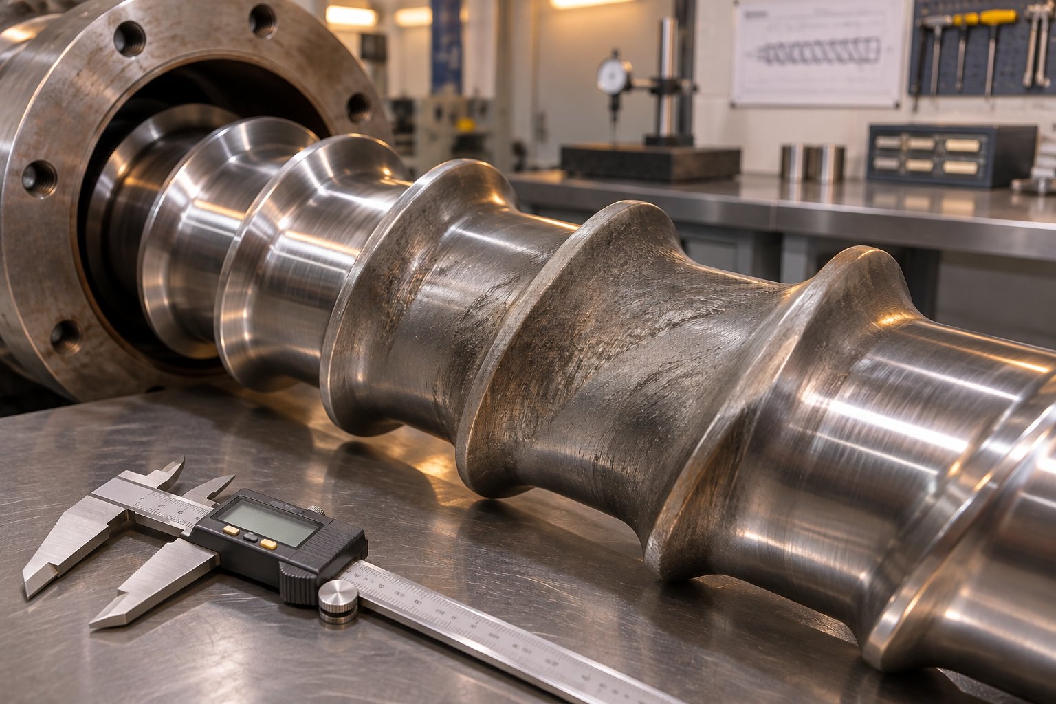
Upstream Factors — Screw and Barrel Condition Affect Melt Quality
You have optimized the die lip, dialed in the right fluoropolymer PPA, and nudged your melt temperature up by a few degrees. The surface improves — but only on three-quarters of the blown-film bubble. One persistent strip still shows sharkskin, or the defect vanishes for an hour and then returns unpredictably. What gives?
The answer often hides far upstream of the die, inside the extruder barrel itself. A worn screw flight, an oversized barrel bore, or uneven compression along the plasticizing channel can deliver a melt stream with hidden viscosity gradients — zones of under-plasticized or thermally inconsistent material that exceed the critical wall shear stress locally, even though the bulk average looks safe on your pressure gauge. This upstream contribution to melt fracture is one of the most frequently overlooked root causes in extrusion troubleshooting, yet it explains a surprisingly large share of intermittent or asymmetric defect patterns that resist every die-side fix.
How Poor Melt Homogeneity Triggers Localized Melt Fracture
Imagine two streams of polyethylene arriving at the die simultaneously. One has been thoroughly sheared and heated to a uniform 220 degrees Celsius; its viscosity sits comfortably below the critical threshold for your die geometry. The other stream — from the same barrel, same screw speed, same temperature setpoint — carries pockets that are five to ten degrees cooler and contain partially entangled chains that never received enough shear energy to fully plasticize. Those cooler, stiffer pockets have higher local viscosity, which means higher local wall shear stress when they pass through the die land. If that localized stress crosses the critical boundary, sharkskin or stick-slip instability appears — but only in the region of the extrudate fed by the inhomogeneous portion of the melt stream.
This is exactly the mechanism that produces the frustrating "one-sided" melt fracture pattern familiar to blown-film operators: the defect shows up on one arc of the bubble but not the other, or it migrates around the circumference over time. It also explains melt fracture down-draw issues in cast film, where periodic thickness variations downstream trace back to viscosity fluctuations that originated in the barrel rather than the die.
What causes this inhomogeneity in the first place? The culprit is almost always degraded screw-and-barrel geometry. Research at Paderborn University demonstrated a direct correlation between screw configuration, throughput, and both thermal and material homogeneity of the melt — measured via radial temperature profiling and gray-value analysis of cross-sectional thin slices. Their findings confirmed that as throughput increases on a given screw, both thermal homogeneity (standard deviation of weighted average melt temperature) and material homogeneity (standard deviation of gray value) deteriorate measurably, and that the screw performance index (SPI) drops in lockstep. A worn screw amplifies this effect because the compromised geometry reduces the energy input available to melt and mix the resin uniformly.
Consider the specific wear scenarios:
- Increased flight-tip clearance: As the gap between the screw flight and barrel wall grows, more polymer leaks backward over the flights instead of being pushed forward. This back-leakage is not just an output problem — it creates pockets of material that experience double or triple the intended shear history alongside pockets that are underworked. The resulting viscosity spread across the melt cross-section can be substantial, particularly with shear-sensitive resins.
- Barrel bore enlargement and ovality: Uneven bore wear — especially the ovality that develops when a deflecting screw wears one side of the barrel more than the other — means the melt film thickness between flight tip and barrel wall varies around the circumference. Thicker melt films receive less shear heating; thinner films receive more. That circumferential temperature gradient propagates all the way to the die.
- Compression-ratio drift: When flight tips in the transition (compression) zone wear down faster than those in the feed zone — a common pattern with abrasive compounds — the effective compression ratio decreases. The screw can no longer compact and melt the solid bed as aggressively as designed. The Paderborn study showed that differences in screw geometry directly influence the degree of melting and thermal uniformity, with poorly configured screws allowing unmelted solids to persist further down the channel.
- Feed-section groove wear: On grooved-feed extruders, worn grooves lose their mechanical grip on pellets, reducing solids-conveying pressure and causing irregular feed pulsations. As screw-barrel design references confirm, grooved feed sections must maintain precise geometry because lost mechanical grip destroys the high-output conveying effect instantly, collapsing throughput stability.
The net result is a melt stream that looks acceptable on an average basis — the melt pressure gauge reads steady, the bulk temperature seems right — but contains hidden heterogeneities that reveal themselves only at the die, where the most stressed zones cross into the instability regime. Diagnosing this requires looking upstream, not just at the die.
Inspecting Screw and Barrel Wear as a Diagnostic Step
Sounds like a lot of effort? The measurement itself is surprisingly straightforward — what matters is consistency, documentation, and knowing which numbers to compare. Here is a practical inspection sequence you can follow during a scheduled shutdown or whenever intermittent defects resist die-side troubleshooting:
- Remove the screw and clean both components: Purge residual polymer from the barrel bore and screw channels using appropriate purge compound or mechanical cleaning tools. Support the screw on a flat surface — a granite inspection table is ideal — and roll it to check for bowing or bending that could indicate deflection damage.
- Measure screw flight OD at multiple stations: Using a calibrated outside micrometer, record the outer diameter of the flight tips at defined positions along the screw: at least one reading in the feed zone, two or three in the transition zone, and one or two in the metering zone. Wear diagnosis best practice recommends measuring at more than one angular orientation at each station to detect asymmetric flight wear.
- Measure barrel bore ID at corresponding stations: Insert a calibrated bore gauge and take readings at the same axial positions, in at least two orientations (0 degrees and 90 degrees) to detect ovality. Electronic bore gauges simplify logging, but a well-maintained analog instrument paired with disciplined record-keeping works just as well.
- Calculate diametral clearance at each station: Subtract screw OD from barrel ID at each corresponding location. Compare the result to the original specification from the machine drawing or documented new-condition baseline. Industry guidance confirms that when diametral clearance exceeds roughly twice the original specification, performance degrades measurably in output, melt quality, and energy efficiency.
- Inspect surfaces visually and document findings: Look for flight-tip rounding, scoring, pitting, corrosion, coating loss, and discoloration at mixing sections or dead zones. Photograph the worst areas. These visual indicators — combined with dimensional data — differentiate abrasive wear from corrosive attack or metal-to-metal contact, each of which calls for a different metallurgical response.
- Compare results against historical records: If previous inspection data exist, calculate the wear rate between inspections. This trend line is more valuable than any single measurement because it tells you how fast the geometry is deteriorating — and when the next service will be needed.
Here is the uncomfortable truth many plants face: this inspection step gets deferred repeatedly because it requires pulling the screw, precise measurement against OEM drawings, and comparison to as-built dimensions that may never have been recorded. Evaluating wear and dimensional matching of screw-barrel assemblies is exactly the kind of work that falls through the cracks — yet it is often the missing diagnostic link between a persistent surface defect and its real upstream cause. For extrusion plants seeking a component-focused resource to evaluate wear, dimensional matching, and plasticizing requirements on single-screw or twin-screw equipment, NANHAIYA's plastic extruder screw-and-barrel support offers a practical route: the company reviews machine information, drawings, photos, and measured dimensions to assess whether custom or replacement screw barrels can restore the plasticizing performance the line needs.
An important caveat belongs here: a replacement screw barrel is not a guaranteed cure for die-related surface defects. If the root cause is a nicked die lip, an unsuitable entry angle, or an incompatible resin-die pairing, new upstream hardware will not fix it. What screw-barrel restoration addresses is the plasticizing contribution — the quality and uniformity of the melt that arrives at the die. It is one essential variable among several, and it must be evaluated alongside die condition, resin selection, and processing-aid strategy rather than in isolation.
When a Screw-Barrel Replacement Genuinely Helps
So your inspection reveals flight-tip clearance that has doubled from the original spec, measurable ovality in the barrel bore through the transition zone, and a compression ratio that has drifted lower as the transition flights wore down faster than the feed section. You are running metallocene LLDPE at near-maximum output with a fluoropolymer PPA already dosed, and one side of the bubble still shows intermittent sharkskin. Does a new screw and barrel actually fix the problem?
In this scenario — where measurable wear-driven melt inhomogeneity has been confirmed as a contributing factor — the answer is very often yes, and here is why. Restoring proper flight clearance, compression ratio, and barrel bore concentricity does three things simultaneously:
- Narrows the melt-temperature distribution: Tighter clearance means more uniform shear heating across the entire melt cross-section. The hot spots and cold spots that create localized viscosity extremes shrink, bringing the worst-case local wall shear stress closer to the average. The Paderborn University research demonstrated that screw configurations with better homogenizing performance — measured by lower standard deviation of weighted average melt temperature — consistently scored higher on the screw performance index. Restoring worn geometry recaptures that homogenizing capability.
- Recovers conveying efficiency: Reduced back-leakage over the flights means the screw delivers more material per revolution at a given RPM. You can often achieve the same throughput at lower screw speed, which translates directly to lower shear rates and lower wall shear stress at the die. That shift alone can move your operating point further from the critical threshold — effectively widening your processing window without touching the die or the resin.
- Stabilizes output over time: Surging and pressure fluctuations caused by worn geometry — the cyclic pattern of solid-bed breakup and erratic conveying — smooth out. Steady melt delivery means the die sees a consistent flow, eliminating the transient spikes in wall shear stress that trigger intermittent defects.
Think of it this way: die-side fixes and processing aids define the boundaries of your melt fracture processing window, while screw-barrel condition determines where within that window your process actually operates. A worn extruder does not shrink the window itself — it pushes your real operating conditions erratically toward the edges, where any boundary excursion causes defects. Restoring the upstream hardware pulls your process back toward the center of the envelope, where margin exists on all sides.
This complementary relationship is key. A new screw barrel paired with a polished die lip, a properly dosed PPA, and a well-matched resin grade creates a system where each lever reinforces the others. Conversely, pouring money into die coatings and premium processing aids while running a badly worn extruder is like upgrading the tires on a car with a bent axle — the new tires help, but they cannot compensate for the upstream problem pulling the vehicle off course.
The logical next step after confirming and correcting every individual contributor — die, resin, PPA, and screw-barrel condition — is to bring all these levers together into a unified framework. Mapping the full processing window and building a prioritized troubleshooting sequence ensures that the next time a surface defect appears, you find and fix the root cause in the right order, without wasting effort on downstream patches while an upstream problem goes undiagnosed.
Building a Wider Processing Window and Systematic Troubleshooting
Every lever discussed so far — die geometry, resin selection, processing aids, temperature adjustments, and screw-barrel condition — acts on a different boundary of the same invisible envelope. That envelope is your melt fracture processing window: the multidimensional space defined by temperature, shear rate, and die pressure within which your extrudate comes out smooth. Step outside any boundary, and defects appear. The challenge is that every combination of resin grade, die design, and upstream equipment condition draws a unique window shape. A metallocene LLDPE on a worn single-screw extruder feeding a tight-gapped spiral die has a very different safe zone than a broad-MWD Ziegler-Natta HDPE on a freshly relined barrel pushing through an optimized pipe head. Troubleshooting, at its core, is the discipline of figuring out which boundary you are closest to — and then applying the lever that moves that boundary most effectively.
Mapping Your Melt Fracture Processing Window
Picture the window as a box with soft edges. On one axis sits shear rate — essentially your line speed and die gap. On another sits melt temperature, which governs viscosity. On a third sits die pressure, influenced by land length, entry angle, and surface friction. Inside the box, the extrudate is defect-free. Push shear rate too high and you cross the critical stress threshold for sharkskin. Drop melt temperature too low and viscosity climbs, shoving wall shear stress past the onset boundary at a throughput that was safe yesterday. Let screw wear introduce viscosity gradients, and localized zones of the melt stream wander outside the window even though the average conditions remain inside it.
The key insight is that every corrective action discussed in earlier sections either widens the window or repositions your operating point within it:
- Fluoropolymer PPAs widen the window by raising the critical wall shear stress for sharkskin onset — the low-stress boundary moves outward.
- Die lip polishing or coating also widens the window by reducing the friction coefficient, which lowers the actual wall stress at any given throughput.
- Increasing melt temperature repositions your operating point by lowering viscosity, pulling the process away from the stress boundary — but the window itself does not change, and thermal degradation imposes its own ceiling.
- Restoring screw-barrel geometry tightens the melt-temperature and viscosity distribution, pulling your worst-case operating condition closer to the average — effectively ensuring you stay inside the window rather than drifting erratically toward its edges.
- Die redesign (entry angle, land length) reshapes the window itself by changing where and how stress builds inside the flow channel.
Identify which boundary of the processing window your operation is closest to, then apply the lever that moves that boundary most effectively. Fixing the wrong boundary wastes time and money while the real constraint remains untouched.
Mapping this window for a specific resin-die combination does not require sophisticated simulation — though rheological modeling helps for high-value products. At a practical level, you can approximate the boundaries through structured trials: run the line at increasing speeds while monitoring extrudate appearance, record the throughput at which sharkskin first appears, note the temperature at which raising melt temp eliminates it, and document the PPA loading at which the onset shifts above your target output. Those data points sketch the edges of your safe zone. Write them down. They become the baseline for every future troubleshooting event on that product.
A Systematic Troubleshooting Sequence
When melt fracture during processing can no longer be ignored — when the defect is on the extrudate and the customer specification is at risk — a prioritized diagnostic workflow prevents the scattershot approach that wastes shifts and material. The sequence below moves from the fastest, lowest-cost diagnostic steps to the most involved interventions, ensuring you rule out simple causes before committing to expensive fixes.
- Identify the melt fracture type. Use the taxonomy from earlier sections. Is it fine surface roughness (sharkskin), alternating smooth-rough bands (stick-slip), or severe helical or chaotic volume distortion (gross)? The type tells you where in the die the instability originates and narrows the corrective options immediately. Melt fracture in LLDPE, for instance, overwhelmingly begins as sharkskin, pointing you toward exit-lip and wall-friction solutions rather than entry-zone redesign.
- Confirm it is melt fracture and not interfacial instability. In coextrusion, perform the water-immersion test described earlier. Surface roughness disappears optically when submerged; interfacial waves do not. Misdiagnosis here is the single most expensive mistake in multilayer troubleshooting.
- Check die condition — lip geometry, land length, surface finish. Inspect the die lip for nicks, buildup, or erosion. Measure land length against resin-supplier recommendations. Run a fingernail across the land surface to detect scratches or worn plating. These are the fastest physical checks and often reveal the root cause — especially if the defect appeared suddenly after a die change, cleaning, or mechanical damage event. Chris Rauwendaal emphasizes that streamlining the die flow channel is always a sound strategy, and a die-land heater retrofit can reduce shear stress enough to eliminate defects while boosting throughput.
- Evaluate resin MWD and consider grade adjustment. If a resin-lot change preceded the defect — a scenario documented in real troubleshooting timelines where a switch to a metallocene-type polyolefin triggered surface roughness — request rheological data from the supplier. Compare the new lot's MWD and critical stress values to the previous lot. A narrower MWD or higher average molecular weight can shift the onset boundary inward, shrinking your safe window. Consider blending with a broader-MWD grade or switching to a resin with more long-chain branching if the product specification permits.
- Trial processing-aid addition at recommended loading. If die condition is acceptable and the resin cannot be changed, introduce a fluoropolymer PPA (or a non-fluorinated alternative where regulatory constraints apply) at the manufacturer's recommended starting concentration. Allow adequate conditioning time — research confirms that fluoropolymer PPAs may need several minutes to establish the die-wall coating. Evaluate extrudate appearance after the coating has fully formed, not during the induction period.
- Inspect screw-barrel dimensional condition for wear-driven melt inhomogeneity. If the defect persists, appears intermittently, or affects only one region of the extrudate (one side of a blown-film bubble, one wall of a profile), the upstream plasticizing system becomes a prime suspect. Measure flight-tip clearance, barrel bore ovality, and compression-ratio drift using the inspection protocol from the previous chapter. For plants that need to confirm dimensional tolerances and evaluate replacement options, NANHAIYA's screw-and-barrel evaluation service provides a component-focused resource for single-screw and twin-screw equipment. Remember that worn components are one contributing factor among many — die-related and resin-related causes must be ruled out first through the steps above.
- Adjust melt temperature as a secondary lever. Raise the melt temperature in small increments (5 to 10 degrees at a time) while monitoring both the extrudate surface and the die lip for drool formation. Capillary rheometer studies on polyethylene have confirmed that increasing processing temperature shifts the critical apparent shear rate for onset significantly upward — from 300 s-1 at 200 degrees Celsius to 800 s-1 at 250 degrees Celsius in one PE study. Effective, but treat it as a secondary lever — it burns through thermal headroom and introduces degradation and die-drool risks.
- Consider die redesign or coating if all else fails. When the defect resists all upstream corrections, PPA additions, and temperature adjustments, the die itself may be fundamentally mismatched to the resin. Options include reducing the entry angle to suppress gross distortion, extending or shortening the land to optimize shear-stress residence time, applying DLC or PTFE coatings to reduce wall friction, or — for high-volume products — commissioning a fully streamlined replacement die. Melt fracture in injection molding follows a parallel logic: gate geometry and runner dimensions must be matched to the resin's critical shear stress, and redesign is the last resort after material and process adjustments have been exhausted.
This sequence is not rigid — experienced troubleshooters sometimes skip steps when the evidence points clearly to one cause. A sudden onset right after a resin-lot change, for example, justifies jumping straight to step four. But when the root cause is ambiguous, working the list in order prevents the common trap of spending thousands on die modifications when the real problem was a worn screw leaking viscosity gradients into the melt stream.
Building Long-Term Melt Fracture Resilience
Fixing today's defect is necessary. Preventing tomorrow's is what separates a reactive operation from a resilient one. Three practices, maintained consistently, transform melt fracture troubleshooting from a crisis-response exercise into a routine quality-assurance function.
1. Routine rheological screening of incoming resin lots. Not every lot of the same grade behaves identically. Molecular weight, MWD, and co-monomer distribution can shift between production campaigns at the resin plant. A simple melt-flow-rate (MFR) check catches gross variations, but it does not reveal MWD differences that affect critical shear stress. Where feasible, periodic capillary rheometer runs on incoming lots — even at just two or three shear rates — build a rheological fingerprint library that flags lots likely to narrow the processing window before they reach the extruder hopper.
2. Scheduled die and screw-barrel inspections. Die lip condition should be checked visually at every die change or cleaning. Screw-barrel dimensional inspections, while more involved, should be calendared at intervals tied to throughput volume and resin abrasiveness — quarterly for glass-filled compounds, semi-annually or annually for unfilled polyolefins. Trend the data. A flight-clearance number in isolation tells you where you are; the rate of change between inspections tells you when the next service window needs to happen.
3. Documenting the confirmed processing window for each product. Every time you successfully troubleshoot a melt fracture event — or every time you qualify a new resin-die combination — record the boundaries: maximum throughput before onset, PPA type and loading, melt temperature range, die-lip condition at the time, and screw-barrel clearance measurements. Store these records where the next shift supervisor or process engineer can find them. The next time a surface defect appears on that product, you will not start from scratch. You will compare current conditions against a known-good baseline and identify the deviation in minutes rather than days.
Melt fracture is not a mystery — it is a boundary condition. Every resin, every die, and every extruder defines a window, and every defect is a signal that the process has drifted outside it. The engineers who master this phenomenon are the ones who map those boundaries deliberately, monitor the variables that shift them, and act on data rather than guesswork. The result is not just smoother extrudate — it is higher throughput, lower scrap, fewer emergency shutdowns, and the confidence to push production closer to the line's true capability without crossing the edge.
Frequently Asked Questions About Melt Fracture
1. What causes melt fracture in polymer extrusion?
Melt fracture occurs when the polymer melt exceeds a critical wall shear stress or shear rate threshold inside or at the exit of an extrusion die. The flowing polymer transitions from smooth, laminar streamlines to an unstable state that imprints surface roughness or volumetric distortion onto the extrudate. Key contributing factors include die geometry (land length, entry angle, lip condition), resin molecular weight distribution, melt temperature, and even upstream screw-barrel wear that introduces viscosity gradients into the melt stream. Linear polymers with narrow MWD, such as metallocene LLDPE, are especially susceptible because they offer less shear thinning, causing wall stress to climb steeply with increasing throughput.
2. What is the difference between sharkskin, stick-slip, and gross melt fracture?
These are three distinct instability types that appear in sequence as shear stress increases. Sharkskin is a fine, regular surface roughness originating at the die exit lip caused by periodic chain disentanglement — it affects only the surface and appears at the lowest critical stress. Stick-slip (oscillating) melt fracture produces alternating smooth and rough bands as the melt cycles between adhering to and slipping from the die wall, driven by pressure oscillations inside the capillary. Gross melt fracture is the most severe form, involving helical or chaotic distortion of the entire extrudate cross-section, triggered by elastic instability in the die entry convergence zone at the highest stress threshold.
3. How do fluoropolymer processing aids eliminate melt fracture?
Fluoropolymer processing aids (PPAs) are immiscible with the host polyolefin resin. During extrusion, the fluoropolymer phase migrates to the die wall and deposits a thin, persistent low-friction coating on internal die surfaces. This coating promotes wall slip, which reduces the actual wall shear stress at any given throughput below the critical onset threshold for sharkskin. PPAs are dosed at very low concentrations — typically 50 to 500 ppm — and require a conditioning period of several minutes before the die-wall coating fully establishes. They are most effective against sharkskin and have limited impact on gross melt fracture originating in the die entry zone.
4. How can worn screw and barrel components contribute to melt fracture?
Worn screw flights and enlarged barrel bores create uneven shear history across the melt stream. Increased flight-tip clearance allows back-leakage, producing pockets of over-sheared and under-sheared material. Barrel bore ovality causes circumferential temperature gradients, while compression-ratio drift from flight wear reduces melting efficiency. These factors deliver a melt with hidden viscosity gradients to the die — localized stiffer zones exceed the critical wall shear stress even when average conditions appear safe. This explains intermittent or one-sided defect patterns on blown-film bubbles. Measuring clearances against original specifications and restoring geometry through replacement screw barrels — evaluated through services like NANHAIYA's screw-and-barrel support at nhyscrews.com — can widen the processing window by improving melt homogeneity.
5. How do you distinguish melt fracture from interfacial instability in coextrusion?
A simple water-immersion test separates the two defects in seconds. Submerge a film sample in water: surface roughness from melt fracture disappears optically because water fills the surface irregularities, making underlying objects look sharp and clear. Interfacial instability lives between coextruded layers inside the film structure, so water cannot reach it — the waviness persists and objects viewed through the film remain blurry. Melt fracture originates at the die lip or entry zone and responds to PPAs, die polishing, or temperature changes. Interfacial instability stems from viscosity or elasticity mismatches between adjacent layers at the merge point and requires equalizing layer viscosities or modifying feedblock geometry.
Written by
Nanhaiya Technical Team
Zhoushan Nanhaiya Plastic Machinery Co., Ltd.
The Nanhaiya technical team supports screw and barrel manufacturing projects through application review, technical communication, custom manufacturing coordination, and production and quality control.
Discuss Your Application
Related Articles
More insights on screw barrel technology and plastics processing.

Injection Molding Color Mixing: From Streaks to Flawless Consistency
Nov 19, 2026
Master injection molding color mixing with expert guidance on colorant types, screw design, process parameters, defect troubleshooting, and Delta E QC protocols.
Read Article
Wrong Extruder Breaker Plate? Spot the Signs Before Scrap Piles Up
Nov 19, 2026
Learn how to select, size, and maintain your extruder breaker plate. Covers hole geometry, pressure drop, polymer-specific specs, and troubleshooting tips.
Read Article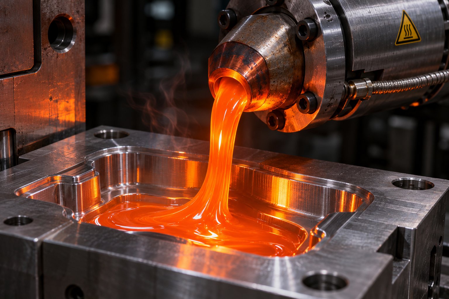
Injection Molding Melt Temperature: Why Your Barrel Settings Lie
Nov 19, 2026
Learn why barrel set points lie about injection molding melt temperature. Complete resin chart, measurement methods, defect troubleshooting, and optimization steps.
Read ArticleLooking for something else?
Search by material, symptom or product and jump straight to the relevant page.
These are navigation suggestions based on keyword matching — not a quotation, not a delivery commitment, and not a substitute for engineering review. Final specification is confirmed by our engineers against your drawings and processed material.
Need help with screw barrel selection?
Share your machine model, processed material and application. Our team can help with pricing and technical support.