

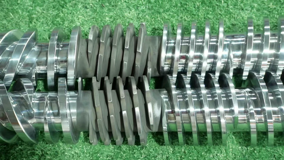
What Is Melt Mixing and Why It Dominates Polymer Processing
Melt mixing is the process of combining two or more components—polymers, fillers, additives, or pigments—in the molten state using thermal energy and mechanical shear to produce a homogeneous compound. It is the most widely used industrial method for creating polymer blends, filled compounds, and specialty formulations at scale. If you have ever wondered why the vast majority of commercial plastic compounds start on an extruder rather than in a reactor or a solvent tank, the answer traces back to this single technique and the practical advantages it carries.
Definition and Core Mechanism
Imagine dropping polymer pellets into a heated barrel. As the material moves forward, it absorbs thermal energy and crosses its melting or softening temperature. At that point, rotating screws or rotors subject the softened mass to intense shear forces. These forces do two critical things simultaneously: they break apart clusters of filler particles or additive agglomerates, and they spread the resulting smaller domains evenly throughout the polymer matrix. The outcome is a melt mix with uniform composition, ready to be shaped into pellets, film, or profiles.
Research into the efficiency of this process confirms that it can be classified into two fundamental actions—distributive mixing (stretching, folding, and rearranging material) and dispersive mixing (reducing the size of filler aggregates or liquid droplets). Both actions happen inside the same equipment, often within different zones of a single screw shaft. Understanding this dual mechanism is what separates a good compound from a mediocre one—a topic explored in depth later in this article.
Melt Mixing vs Solution Mixing vs In-Situ Polymerization
Three principal routes exist for compounding polymers with other materials, and each comes with distinct trade-offs:
- Melt mixing (melt compounding): Components are combined above the polymer's softening point using mechanical shear. No solvents are needed, and the process integrates directly into continuous extrusion lines—making it the dominant industrial choice.
- Solution mixing: The polymer and fillers are dispersed in a common solvent, then the solvent is evaporated. This route can achieve fine filler dispersion because the low-viscosity medium allows ultrasonic or high-speed agitation, but it restricts you to solvent-soluble polymers and demands solvent recovery infrastructure. As one comprehensive review of nanocomposite fabrication notes, polymers insoluble in conventional low-boiling-point solvents—such as polyethylene—simply cannot be processed this way.
- In-situ polymerization: Nanofillers are dispersed in the monomer first, and then polymerization occurs around them. The method can yield excellent nano-scale dispersion, yet it requires elaborate reaction control, specific chemical agents, and waste-handling facilities that complicate scale-up.
The melt-based route wins on practicality. It is environmentally friendlier because it eliminates organic solvents, it is compatible with existing extrusion and injection-molding infrastructure, and it accommodates a wide range of polymer types—from hydrophilic EVOH to completely hydrophobic perfluoropolymers. Even in the food-product space, the idea of combining dry ingredients into a heated, mixed state echoes broadly; think of how a cinnamon muffin melt mix relies on controlled heat and thorough blending to achieve consistent flavor. The polymer world simply replaces flavor with performance properties, and the oven with a twin-screw extruder.
Clarifying Terminology Overlaps
One source of confusion for engineers and researchers alike is the interchangeable use of closely related terms. You will encounter "melt mixing," "melt blending," and "melt compounding" in both academic literature and supplier data sheets, sometimes referring to the exact same process.
Terminology note: "Melt compounding" typically implies the addition of fillers, reinforcements, or functional additives to a polymer matrix. "Melt blending" often refers strictly to polymer-polymer systems without particulate fillers. "Melt mixing" is the broadest umbrella term, covering both scenarios. In practice, all three describe the same core mechanism—combining materials in the molten state under shear—so context determines the precise meaning. When reading a mixed melting point study in analytical chemistry, keep in mind that this is an entirely different concept: it refers to the depression of a substance's melting point when mixed with an impurity, not to polymer processing.
With the definition, mechanism, and terminology landscape established, the real engineering challenge comes into focus: how do you actually control what happens inside the melt? The answer lies in two mixing mechanisms—dispersive and distributive—that every screw rotation must deliver simultaneously.
Dispersive and Distributive Mixing Mechanisms Explained
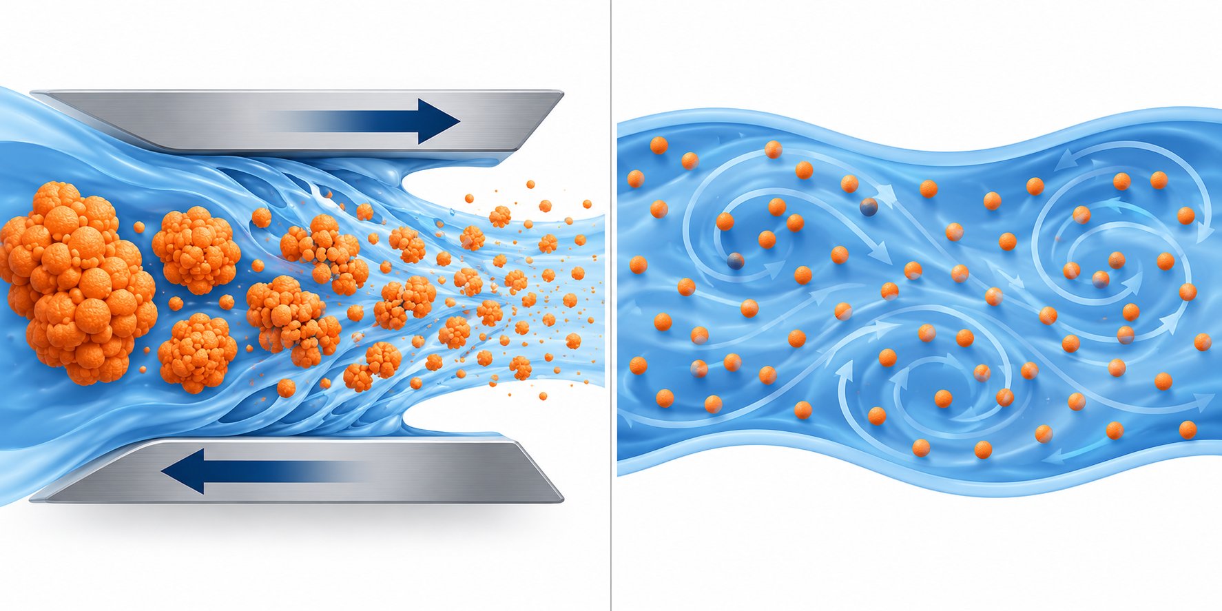
Every melt mixing operation—whether it runs on a lab-scale batch mixer or a production twin-screw extruder—depends on two distinct mechanisms working in concert. Dispersive mixing breaks things apart. Distributive mixing spreads them around. Sounds simple? The engineering reality is anything but, because each mechanism demands different flow conditions, different screw element geometries, and different stress levels. Confusing one for the other is surprisingly common. As one industry expert notes, engineers frequently claim they need to improve dispersion when they actually need an additive distributed more uniformly—or they install distributive elements when the real problem is stubborn agglomerates that need to be shattered first.
Dispersive Mixing and Stress Thresholds
Dispersive mixing is all about force. Its job is to break cohesive clusters—filler agglomerates, droplets of a minor polymer phase, pigment clumps—into their smallest achievable primary units. For this to happen, the shear or elongational stress imposed on the cluster must exceed its cohesive strength. Think of carbon black: during combustion, individual particles fuse into aggregates, and those aggregates cling together through weak van der Waals forces to form larger agglomerates. The extruder must apply enough stress to rupture those inter-aggregate bonds without necessarily breaking the fused aggregates themselves, since aggregates represent the ultimate minimum particle size.
Two stress-based mechanisms drive this break-up: rupture and erosion. Rupture requires a high instantaneous stress that snaps the agglomerate apart in a single event. Erosion works more gently, peeling material from the agglomerate surface over a longer residence time. A 2024 study from the University of Paderborn analyzed these effects using 3D CFD simulations with particle tracking on a co-rotating twin-screw extruder. The researchers found that toothed mixing elements (ZME) generated the highest and most uniformly distributed shear stresses across particles, making them especially effective for dispersive duty. Kneading blocks with a 45-degree stagger angle also performed well, though their shear stress distribution was less even.
In practical screw design, dispersive mixing is promoted by wide kneading discs. A wide disc plows through the molten polymer, creating a pool of material in front of it and smearing it under high shear as the disc rotates. Increasing the stagger angle toward 90 degrees—or adding reverse-pumping elements—restricts forward flow, forces the mixing zone to fill completely, and increases the work applied to the compound. The trade-off? More dispersive intensity means higher melt temperatures from viscous dissipation, which can degrade heat-sensitive polymers. Similar to how you would not crank the heat to maximum when preparing an ice melt mix for a driveway—too aggressive a formulation damages the surface it is meant to protect—excessive shear in an extruder damages the very polymer it is meant to improve.
Distributive Mixing and Flow Reorientation
Distributive mixing serves a completely different purpose. Instead of reducing particle size, it rearranges already-broken-down domains so they are spread uniformly throughout the melt volume. Imagine squeezing a drop of food coloring into cake batter: the color is already at its smallest scale, but you still need to fold and stir until the batter shows no streaks. That folding action—repeated splitting, reorientation, and recombination of flow streams—is exactly what distributive mixing accomplishes in a polymer melt.
In a twin-screw extruder, distributive mixing is promoted by narrow kneading discs and specialized toothed or slotted elements. Narrow discs slice through the melt in a scissoring action rather than plowing through it. Each disc divides the flow, and the next disc recombines it at a different orientation—much like an extruder melt tube static mixer splits and recombines streams in a pipe. The Paderborn study confirmed that toothed mixing elements achieved the best distributive mixing index (MQ), followed closely by 90-degree kneading blocks with standard disc widths. Conveying elements and short kneading blocks performed significantly worse, leaving visible particle accumulations near the barrel wall even at moderate screw speeds.
Rotation speed matters here too. Increasing RPM improved the distributive mixing index across all element types tested. At 200 RPM, the short kneading block (KB12) showed an MQ value around 2.38; doubling the speed to 400 RPM cut that value nearly in half. The mixed melting point concept from analytical chemistry—where blending two substances alters their thermal behavior—offers a loose analogy: just as molecular-level intermixing changes physical properties, thorough distributive mixing at the macro level changes the compound's mechanical and optical uniformity.
Why Both Mechanisms Must Work Together
Here is where many operations fall short. A compound can be distributed but not dispersed—particles are spread evenly, yet they remain as large, visible agglomerates that create weak spots, color streaks, or surface defects. Conversely, a compound can be dispersed but not distributed—agglomerates are shattered into fine particles, yet those particles cluster in one region of the melt, producing composition gradients and inconsistent part performance.
| Parameter | Dispersive Mixing | Distributive Mixing |
|---|---|---|
| Primary function | Break agglomerates into primary particles | Spread particles uniformly throughout the melt |
| Stress requirement | High shear or elongational stress exceeding cohesive strength | Low to moderate stress; relies on repeated flow reorientation |
| Dominant equipment zones | High-shear kneading sections with wide discs and restrictive elements | Mixing sections with narrow discs, toothed elements, or slotted geometries |
| Typical screw elements | Wide kneading blocks (e.g., KBW 45/5/30), reverse elements, high stagger angles | Narrow kneading blocks (e.g., KP 45/5/20), toothed mixing elements (ZME), gear-type mixers |
| Quality outcome controlled | Final particle or droplet size; absence of visible agglomerates | Composition uniformity; absence of concentration gradients or streaks |
| Failure symptom | Visible specks, gels, or undispersed filler clusters | Blotchy color, property variation across a part, or uneven filler loading |
In real-world compounding, both mechanisms occur simultaneously within the same screw section, but they can be biased toward one or the other through element selection. A tyler mixer melts and blends confectionery ingredients by balancing heat and agitation; a twin-screw compounder does essentially the same for polymer systems, except the agitation is engineered at the element level. Wide-disc kneading blocks followed by a neutral or reverse element create a highly filled, high-shear zone that favors dispersion. Narrow-disc kneading blocks or toothed elements in a forward-conveying arrangement favor distribution with gentler energy input.
The critical takeaway: screw or rotor design is the primary engineering lever for balancing dispersive and distributive action. Get the balance wrong, and no amount of temperature adjustment or speed tweaking will compensate. Get it right, and you unlock consistent compound quality—setting the stage for the next decision, which is choosing the right equipment platform to house that screw design.
Equipment for Melt Mixing: From Batch Mixers to Twin-Screw Extruders
Balancing dispersive and distributive action is only half the puzzle. The other half is choosing a machine platform that can physically deliver the shear profiles, residence times, and throughput rates your formulation demands. Three principal equipment categories dominate melt mixing today: internal (batch) mixers, single-screw extruders, and co-rotating twin-screw extruders. Each occupies a distinct niche, and understanding their strengths and limits prevents costly mismatches between the formulation on paper and the compound that actually exits the die.
Internal Batch Mixers and Their Role
Picture an enclosed chamber with two counter-rotating rotors spinning inside it. A hydraulic ram presses raw material down into the rotors, forcing the charge through narrow gaps where intense shear does the heavy lifting. That, in essence, is an internal batch melt mixer—commonly known by trade names like Banbury or by laboratory-scale variants such as the Haake Rheomix.
Internal mixers excel in situations that call for high shear intensity on viscous, difficult-to-process materials. Rubber compounding is the classic example: incorporating carbon black, silica, oils, and curatives into an elastomer matrix demands enormous mechanical energy, and the enclosed chamber keeps volatile ingredients from escaping. Operators can monitor rotor speed, torque, temperature, and mixing time during each batch cycle, adjusting parameters in real time if the torque curve signals incomplete filler incorporation.
Beyond rubber, internal mixers remain popular for small-batch R&D and formulation screening. When you only need 50 grams to test a new pigment loading or validate a compatibilizer, firing up a full-scale extrusion line is impractical. A lab-scale internal mixer lets you iterate quickly, evaluate the mixed melting point method of a new blend system under controlled thermal conditions, and gather torque-versus-time data that hints at how the material will behave during scale-up.
The limitation? Internal mixers are inherently batch devices. Each cycle requires loading, mixing, and discharging the compound—often onto a two-roll mill or into a downstream extruder for pelletizing. That stop-start workflow caps throughput and introduces batch-to-batch variability, which is why high-volume thermoplastic compounding has largely migrated to continuous platforms.
Single-Screw vs Twin-Screw Extruders
Single-screw extruders are the workhorses of plastics forming—film lines, pipe extrusion, profile production—but they were never designed primarily as mixers. Their operating principle is drag flow: the polymer melts against the heated barrel wall and is dragged forward by screw rotation. The shear rate peaks at the barrel surface and drops toward zero at the screw root, creating a velocity gradient that limits how thoroughly the channel contents can be turned over.
As extrusion veteran Jim Frankland explains, the polymer in a single-screw channel tends to stay in roughly the same radial position because of continuing shear-thinning effects from barrel to root. Engineers have tried to overcome this with barrier flights, Maddock-type mixers, and other flow-interrupting devices, but each one creates a pressure drop that reduces output and raises melt temperature. Multiple high-shear sections become impractical because the cumulative pressure loss and thermal penalty are too severe.
Twin-screw extruders solve this problem fundamentally. In a co-rotating intermeshing design, the two screws can transfer the entire channel contents from one screw to the other—repeatedly. This full-channel turnover delivers intensive mixing with far less pressure drop per mixing event, because the intermeshing flights act as positive displacement elements that maintain forward conveyance even as material is folded and reoriented. The screws typically run in a starved-fed condition, meaning the barrel is not completely filled at every point, which provides available volume for these screw-to-screw transfers and allows dedicated functional zones along the barrel length.
| Feature | Internal Batch Mixer | Single-Screw Extruder | Co-Rotating Twin-Screw Extruder |
|---|---|---|---|
| Operating mode | Batch | Continuous | Continuous |
| Mixing intensity | High (enclosed chamber, controlled ram pressure) | Low to moderate (drag-flow limited) | High (modular elements, screw-to-screw transfer) |
| Throughput scalability | Limited by batch size and cycle time | Good for forming; modest for compounding | Excellent—scales from lab to multi-ton/hr lines |
| Configuration flexibility | Fixed rotor geometry; adjustable speed and time | Limited to flight and mixer inserts | Fully modular screw and barrel sections |
| Degassing capability | Limited without auxiliary equipment | Possible but constrained | Integrated vacuum vent zones |
| Primary application | Rubber compounding, R&D screening | Polymer forming, simple color blending | Thermoplastic compounding, masterbatch, nanocomposites |
The practical takeaway: if your goal is simply to melt a single resin and push it through a die, a single-screw extruder is efficient and cost-effective. The moment you need to disperse fillers, blend immiscible polymers, or incorporate reactive additives, a twin-screw platform gives you the mixing control that a single screw physically cannot match.
Modular Screw Architecture and Functional Zones
What truly sets co-rotating twin-screw extruders apart is their modular barrel-and-screw architecture. Instead of a single monolithic screw, the shafts accept interchangeable elements—conveying flights, kneading blocks, toothed mixers, and reverse-pumping segments—that slide on and lock via splined connections. Engineers assemble these elements in a specific sequence to create distinct functional zones, each optimized for a different stage of the compounding process.
Here are the key functional zones and the element types that build them:
- Solids conveying zone: Deep-flighted, large-pitch conveying elements rapidly move raw pellets or powder away from the feed throat and prevent bridging. The barrel may be cooled to keep material free-flowing.
- Melting/plasticization zone: Staggered kneading blocks (typically 30- to 60-degree stagger angles) apply intensive shear to convert solid pellets into a continuous melt. Wider discs and tighter stagger angles increase energy input and accelerate melting.
- Mixing zone: Narrower kneading discs, toothed mixing elements (ZME), or gear-type distributive mixers blend the melt to compositional uniformity. This is where additives, pigments, or a secondary polymer phase are incorporated and spread evenly.
- Venting/devolatilization zone: Deep-flighted conveying elements with large pitch create a partially filled, low-pressure region. Vacuum ports in the barrel extract moisture, trapped air, or residual volatiles—critical for compounds that would otherwise exhibit surface defects or voids.
- Pressure build-up zone: Tight-pitch conveying elements at the screw tip generate the pressure needed to push the melt through a die plate or strand die for pelletizing. Element pitch, length, and barrel temperature all influence the final discharge pressure.
Each zone's performance hinges on element geometry, stagger angle, and pitch. A 90-degree kneading block, for instance, acts almost as a flow restriction—it neither pumps forward nor backward—making it useful as a melt seal before a vent port. A 30-degree forward kneading block, by contrast, provides modest shear while still conveying material downstream. Swapping just a few elements can shift residence time distribution, shear history, and the balance between dispersive and distributive action across the entire barrel length.
This modularity is why screw configuration is widely regarded as the central design decision in twin-screw compounding. Two processors running identical raw materials on the same machine model can achieve dramatically different compound quality simply by rearranging the element sequence. In analytical chemistry, you might define mixed melting point as a technique for verifying compound identity through thermal behavior; in polymer compounding, the equivalent diagnostic tool is the screw configuration itself—it defines how thoroughly the thermal and mechanical history of the melt is controlled from feed to discharge.
Yet even the most elegant screw layout means little if the processing parameters feeding it are wrong. Temperature, screw speed, feed rate, and back-pressure each interact with element geometry in ways that can either amplify or undermine the intended mixing outcome—a topic that deserves its own careful examination.
Processing Parameters That Control Melt Mixing Quality
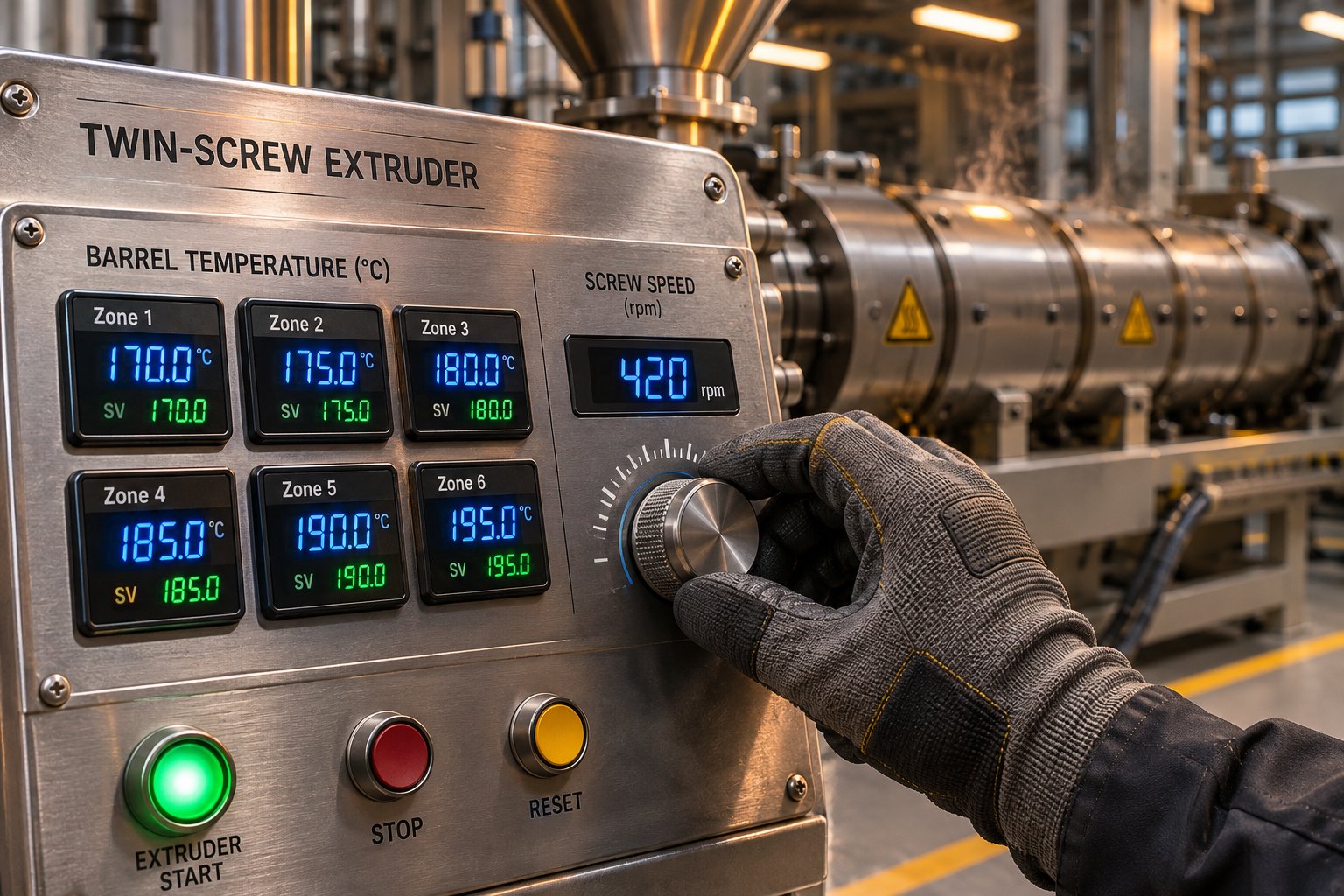
A carefully sequenced screw design gives you the potential for excellent mixing. Whether that potential is realized depends entirely on the processing parameters you dial in—and on how those parameters interact with one another. Temperature, screw speed, feed rate, and back-pressure form a tightly coupled system: change one, and the others shift in ways that can either sharpen or sabotage compound quality. Understanding these interdependencies is what separates a stable, optimized melt mixing process from one that drifts between acceptable and out-of-spec.
Temperature Profile and Viscosity Control
The barrel temperature profile is your first and most direct lever for controlling melt viscosity. Set the zones too cold, and the polymer stays too viscous to flow through kneading blocks efficiently—torque spikes, throughput drops, and undispersed agglomerates survive the mixing section. Set them too hot, and the melt becomes so fluid that shear stresses collapse below the threshold needed for dispersive mixing. Worse, excessive temperature accelerates thermal degradation, chain scission, and discoloration in heat-sensitive resins like PVC or PLA.
In practice, compounders rarely run a flat temperature profile from feed to die. A typical strategy ramps barrel temperatures upward through the melting zone to ensure complete plastication, holds a moderate setpoint through the mixing section to maintain useful viscosity, and may reduce temperature near the die to cool the melt before pelletizing. The barrel setpoint, however, is not the melt temperature—viscous dissipation inside filled kneading sections can push the actual polymer temperature 20-40 °C above the barrel wall. This gap widens at higher screw speeds and with more viscous formulations, making melt temperature monitoring (via immersion thermocouple or IR probe) far more informative than barrel-zone readings alone.
Think of it like cooking: do you put melted butter in pancake mix at a rolling boil, or do you let it cool slightly so it blends in without cooking the eggs? Temperature management in melt mixing follows the same logic—just enough heat to enable flow, but not so much that you damage the ingredients.
Screw Speed, Shear Rate, and Energy Input
Screw speed (RPM) is the parameter that most directly controls shear rate. Higher RPM means faster relative motion between screw flights and the barrel wall, which raises the velocity gradient acting on the melt. For dispersive mixing, that translates into higher stress on filler agglomerates and polymer droplets—exactly what you want when trying to break stubborn clusters apart.
The relationship is not free of cost, though. Greater screw speeds deliver more mechanical energy input in the mixing zones, resulting in a greater melt temperature. This viscous dissipation effect is especially pronounced in fully filled kneading blocks, where every gap between disc and barrel converts rotational energy into heat. For a polymer like nylon 6,6 that tolerates high processing temperatures, the thermal penalty may be acceptable. For a temperature-sensitive biopolymer, it can mean the difference between a functional compound and a degraded one.
Screw speed also has a secondary influence on residence time, though this effect is smaller than many engineers assume. Research on twin-screw compounding confirms that throughput has a considerably larger impact on residence time than RPM does. Increasing screw speed modestly shortens the time material spends in the barrel, but the dominant factor is how fast new material is being fed in—which brings us to feed rate.
Feed Rate, Fill Level, and Back-Pressure
Co-rotating twin-screw extruders typically run starved-fed: a gravimetric or volumetric feeder meters material into the barrel at a controlled rate independent of screw speed. This decoupling is powerful because it lets you adjust the degree of fill in each barrel section. A higher feed rate at constant RPM increases the fill level, ensuring kneading blocks operate fully filled and apply maximum shear. A lower feed rate leaves kneading zones partially starved, reducing energy input and shear stress but extending the residence time distribution.
Larger throughput reduces both the average residence time and the width of the residence time distribution, tightening the thermal history each particle of compound experiences. For reactive processes or thermally sensitive blends, that narrower distribution translates directly into more consistent product quality. The mixed melting point procedure used in analytical chemistry illustrates an analogous principle: a controlled, consistent thermal exposure reveals true material identity, whereas erratic heating produces ambiguous results.
Back-pressure—generated by the die plate, screen pack, or downstream pelletizer—also shapes fill level and residence time. Higher die restriction forces melt back upstream, extending the length of fully filled zones and increasing the pressure-driven component of flow. Moderate back-pressure can improve mixing by keeping kneading sections fully engaged, but excessive restriction raises melt temperature and can cause surging or die drool.
| Parameter | Primary Effect on Mixing | Common Trade-Off |
|---|---|---|
| Barrel temperature profile | Controls melt viscosity; determines stress transfer to fillers and dispersed phases | Too high degrades polymer; too low causes incomplete melting and excessive torque |
| Screw speed (RPM) | Directly sets shear rate; increases dispersive mixing intensity | Higher RPM raises melt temperature via viscous dissipation; may degrade heat-sensitive resins |
| Feed rate (throughput) | Governs fill level and residence time distribution; affects whether kneading zones are fully or partially filled | Higher throughput shortens residence time—less mixing time per unit mass; lower throughput extends time but may overshear |
| Back-pressure (die restriction) | Extends fully filled zones; increases pressure-driven mixing upstream of the die | Excessive back-pressure raises melt temperature and causes surging or die instability |
| Screw configuration | Defines the spatial distribution and intensity of dispersive vs. distributive zones | More aggressive mixing elements increase energy input and wear; gentler designs may leave agglomerates intact |
Specific Mechanical Energy as a Scaling Metric
With so many interacting parameters, how do you compare a process running at 200 RPM and 10 kg/h on a 26-mm lab extruder with one running at 150 RPM and 300 kg/h on a 92-mm production line? The answer is specific mechanical energy (SME)—the total mechanical energy transferred from the motor through the screws and into each kilogram of compound, typically expressed in kWh/kg.
SME captures the cumulative thermo-mechanical history in a single number. It accounts for screw speed, torque, and throughput simultaneously, which is why it has become the go-to metric for scale-up decisions. A detailed case study scaling a masterbatch from a 26-mm to a 92-mm twin-screw extruder demonstrated this vividly. The lab-scale process achieved an optimized SME of 0.083 kWh/kg. When the identical screw design and temperature profile were transferred directly to the 92-mm machine, the SME dropped to just 0.026 kWh/kg—a 69% shortfall. The result was catastrophic: solid, unmolten pellets discharged through the diverter valve, and the process could not produce usable product.
Root-cause analysis revealed that the larger extruder's reduced area-to-volume ratio limited heat transfer, and a low-viscosity raw material created a lubricating effect along the barrels and screws. Only after the screw design was reworked and the temperature profile and speed were adjusted did the SME climb to 0.086 kWh/kg—closely matching the lab-scale reference. At that point, the process stabilized, the melt became fully homogeneous, and the expected throughput scale-up factor was achieved.
The lesson is straightforward: matching SME across scales is a necessary condition for matching product quality. It is not the only condition—residence time distribution, peak shear rate, and melt temperature profile also matter—but without SME alignment, the other parameters lose their meaning. Much like the mixed melting point technique in chemistry, where two supposedly identical substances are confirmed by comparing their thermal behavior side by side, SME lets engineers confirm that two processes at different scales are delivering equivalent mechanical work to the compound.
Parameters, however, do not operate in a vacuum. The polymers and additives being processed bring their own viscosity, crystallinity, and shear-sensitivity into every interaction—properties that fundamentally shape which parameter window will produce an acceptable compound and which will not.
How Polymer Properties Shape Melt Mixing Behavior
You can perfect your screw configuration, dial in optimal barrel temperatures, and match SME targets to the decimal—yet still produce a subpar compound. Why? Because the polymers and additives you feed into the extruder carry intrinsic properties that dictate how they respond to every parameter you set. Viscosity, crystallinity, molecular weight, and thermal transitions all interact with your processing window in ways that no amount of parameter tuning can override if you have not accounted for them upfront. This is the gap most troubleshooting guides skip: the material itself is half the equation.
Viscosity Ratio and Blend Morphology
When blending two immiscible polymers, the single most influential material property is the viscosity ratio—the viscosity of the dispersed phase divided by the viscosity of the matrix. This ratio determines how the minor phase deforms, breaks up, and ultimately distributes under shear. Conventional wisdom holds that when the viscosity ratio approaches unity (K ≈ 1), the minor phase disperses most readily into fine, uniform droplets because the matrix can efficiently transfer shear stress to the dispersed domains.
Reality, however, is more nuanced. A study on PS/PP blends from Hasselt University and the Université de Blida challenged this expectation by keeping the PS matrix constant and varying the viscosity of dispersed PP across four grades. Blends with K >> 1—where the dispersed PP was far more viscous than the PS matrix—actually produced the finest, most homogeneous microstructure. The high-viscosity PP particles resisted coalescence while the lower-viscosity matrix acted as a lubricant, preventing re-agglomeration. Most strikingly, only the high-K blend spontaneously formed a unique microfibrillar morphology, with PP fibrils reaching up to 50 micrometers in length and aspect ratios above 20.
Blends where K << 1, by contrast, showed the opposite behavior. The low-viscosity PP domains coalesced readily within the more viscous PS matrix, producing larger, coarser droplets and a less uniform dispersion. The researchers concluded that the overall melt viscosity of the blend—not just the ratio between phases—plays a dominating role: high total blend viscosity generates high internal shear stresses and dispersive forces that deform droplets without allowing coalescence.
What does this mean practically? If you are blending two polymers and getting coarse morphology despite adequate screw speed, do not automatically assume you need more shear. Check the viscosity ratio first. You may need to select a different grade of the dispersed polymer, adjust the processing temperature to shift relative viscosities, or introduce a compatibilizer that modifies interfacial tension. Understanding what is mixed melting point in analytical chemistry helps verify compound identity through thermal behavior; understanding viscosity ratio in polymer blending helps predict compound morphology through rheological behavior. Both are diagnostic tools—just applied to very different problems.
Crystallinity, Glass Transition, and the Processing Window
Every polymer carries a thermal fingerprint that defines when and how it can be processed. For semi-crystalline polymers like polypropylene, polyethylene, or nylon, the melting temperature (Tm) is a hard boundary: barrel zones must exceed Tm to ensure complete plastication. Isotactic PP, for instance, melts between approximately 160-170 °C, so processing typically starts at 180 °C or higher. Fall below that threshold, and unmelted pellets survive the mixing section—exactly the failure mode seen in the scale-up case study discussed earlier.
Amorphous polymers like polystyrene, polycarbonate, or PMMA behave differently. They lack a sharp melting transition and instead soften gradually above their glass transition temperature (Tg). Polystyrene, with a Tg around 90 °C, becomes processable well below the temperatures needed for semi-crystalline resins. This gradual softening gives amorphous polymers a wider processing window but also means viscosity changes more predictably with temperature—a useful characteristic for fine-tuning shear conditions.
Blending a semi-crystalline polymer with an amorphous one introduces complexity. The PS/PP blend research demonstrated that the Tg of the PS matrix increased in the blends compared to pure PS—not because of chemical interaction, but because dispersed PP droplets physically constrained the molecular relaxation of the amorphous PS chains, acting as barriers similar to inert glass-bead fillers. Meanwhile, the melting temperature of the dispersed PP decreased in the blends relative to neat PP, with the most pronounced drop occurring in the finest microstructures where homogeneous nucleation dominated.
The practical implication is clear: your processing window is not simply the Tm or Tg of each component read from a data sheet. It is the overlap zone where all components are simultaneously above their softening or melting points yet below their degradation thresholds. For blends, this overlap can be surprisingly narrow—sometimes only a 20-30 °C window separates incomplete melting from thermal decomposition.
- Melt viscosity: Determines the stress the matrix can transfer to dispersed phases or filler particles. Higher viscosity means higher shear stress at a given screw speed—beneficial for dispersive mixing but demanding more motor torque.
- Viscosity ratio (K = ηdispersed / ηmatrix): Controls droplet deformation and break-up dynamics. Values near unity are traditionally favored, though recent research shows K >> 1 can yield finer morphologies in certain systems.
- Melt flow index (MFI): A practical, single-point proxy for melt viscosity measured under standard conditions (e.g., 230 °C / 2.16 kg for PP). Higher MFI indicates lower viscosity and easier flow—but also signals lower molecular weight and potentially weaker mechanical properties.
- Molecular weight (Mw) and molecular weight distribution (MWD): Higher Mw raises viscosity and elastic response; broader MWD increases shear sensitivity. Pilot-scale reactive extrusion studies show that narrowing MWD through peroxide-initiated chain scission reduces non-Newtonian behavior and can improve processability for applications like fiber spinning.
- Crystallinity and Tm: Define the minimum barrel temperature for semi-crystalline polymers. Higher crystallinity increases the enthalpy required for melting, demanding more energy input in the plasticization zone.
- Glass transition temperature (Tg): Sets the lower bound for processing amorphous polymers. Ranges vary enormously—from -110 °C for HDPE to 275 °C for polyamide-imide—so material selection directly constrains the temperature profile.
- Thermal stability / degradation ceiling: The upper bound of the processing window. Exceeding it causes chain scission, crosslinking, discoloration, or volatile generation—all of which degrade compound quality.
Shear-Thinning Behavior in Practical Terms
Most polymer melts are non-Newtonian: their viscosity decreases as shear rate increases—a phenomenon called shear thinning. At low shear rates, polymer chains are entangled and resist flow, producing high apparent viscosity. As shear rate climbs, chains align in the flow direction, disentangle, and slide past one another more easily. The viscosity can drop by an order of magnitude or more between the near-zero-shear plateau and high-rate processing conditions.
This behavior is both a blessing and a complication for melt mixing. On the positive side, it means that twin-screw extruders operating at high screw speeds effectively reduce the apparent viscosity of the melt, lowering torque requirements and enabling the polymer to flow into tight clearances where mixing occurs. A dynamic melt mixer exploiting this principle can process high-viscosity engineering resins that would stall a lower-shear device. On the negative side, shear thinning means the stress the matrix exerts on filler agglomerates or dispersed polymer droplets does not scale linearly with screw speed. Doubling RPM does not double the shear stress—it delivers diminishing returns because the melt becomes progressively thinner.
The Carreau-Yasuda model captures this behavior mathematically, describing how viscosity transitions from a Newtonian plateau at low shear rates to a power-law decay at high rates. The PS/PP blend study used this model to extract zero-shear viscosity and relaxation time constants for each polymer grade. The critical shear rate (1/λ) at which thinning begins varied significantly across PP grades: high-MFI (low molecular weight) PP showed thinning onset at much higher shear rates, while low-MFI PP—with its longer chains and denser entanglement network—began thinning earlier. In a dynamic melt mixer or twin-screw compounder, this means you can shift the effective processing regime by choosing a different polymer grade, not just by changing RPM.
Consider the reactive extrusion data from pilot-scale CR-PP production: adding just 200 ppm of peroxide to a PP with an MI of 4 substantially reduced complex viscosity and expanded the Newtonian plateau to higher frequencies. The chain scission shortened the polymer backbone, reduced entanglements, and made the melt less shear-sensitive. In practical terms, the modified resin flowed more uniformly across the operating range—exactly the kind of rheological tuning that simplifies parameter selection for downstream melt mixing or fiber spinning.
The interplay works both ways, too. Just as adding melted butter to cake mix changes the batter's flow behavior—too much and the batter runs thin, too little and it stays lumpy—adjusting the molecular architecture of your polymer feedstock changes how it responds to every processing parameter. MFI, molecular weight distribution, crystallinity, and shear-thinning characteristics are not fixed obstacles; they are design variables you can manipulate through grade selection, additive packages, or reactive processing to bring the material's behavior into alignment with your screw configuration and parameter targets.
Material properties set the boundaries. Processing parameters operate within those boundaries. But for an increasingly important class of compounds—polymer nanocomposites—the boundaries tighten dramatically, because nano-scale fillers introduce surface-area effects, agglomeration forces, and viscosity spikes that push conventional parameter windows to their limits.

Melt Mixing for Polymer Nanocomposites and Filler Dispersion
Nano-scale fillers amplify every challenge discussed so far. Their enormous surface area drives viscosity upward, their van der Waals attraction pulls them into stubborn agglomerates, and their sensitivity to excessive shear means that the same mechanical energy needed to peel platelets apart can also snap polymer chains in half. Yet melt mixing remains the route most researchers and manufacturers choose when the goal is to move a nanocomposite from lab curiosity to commercial product. The reasons are practical, the challenges are real, and the strategies for overcoming them differ significantly depending on whether you are working with clay, graphene, or carbon nanotubes.
Why Melt Mixing Suits Nanocomposite Scale-Up
Imagine you have developed a promising polymer-clay nanocomposite using solution mixing in the lab. The X-ray diffraction pattern shows beautifully exfoliated platelets, and the tensile modulus has jumped 40%. The next question your production team asks is: how do we make 500 kg/h of this? Solution mixing immediately hits a wall—solvent procurement, explosion-proof reactors, evaporation energy, solvent recovery systems, and environmental permitting. In-situ polymerization demands monomer handling, reaction control, and catalyst management that most compounding plants simply are not equipped for.
Melt mixing sidesteps all of that. The nanofiller is pre-weighed, fed into the same twin-screw extruder already running your base resin, and dispersed through the same kneading blocks and mixing elements your team already understands. No solvents. No reactors. No new waste streams. The process slots directly into existing extrusion infrastructure, and parameter adjustments—screw speed, temperature profile, element configuration—are the same levers engineers use for any filled compound.
This compatibility with standard equipment is the single biggest reason the technique dominates industrial-scale nanocomposite production. A NIOSH-archived study comparing nanocomposite dispersion across several melt mixers reinforced this point, evaluating how different equipment platforms handle nano-scale filler distribution and confirming that conventional compounding hardware—when configured correctly—can achieve meaningful dispersion improvements without specialized machinery. The study underscored that mixer selection and screw design matter far more than exotic equipment when scaling nanocomposite production.
There is also a tunability advantage. By rearranging screw elements, you can independently dial up dispersive intensity in one zone (to shatter agglomerates) while preserving gentler distributive action downstream (to spread the liberated particles without overheating the melt). That zone-by-zone control is something neither solution mixing nor in-situ polymerization can replicate—they apply energy globally, not locally.
Dispersion Challenges and Compatibilization Strategies
If the process is so accessible, why do so many nanocomposite compounds still fall short of their theoretical property gains? The answer lies in the physics of nano-scale dispersion. Consider montmorillonite clay: each platelet is roughly 1 nm thick and 100-500 nm across, stacked into tactoids held together by electrostatic forces and shared interlayer cations. Fully exfoliating those stacks—separating every platelet into an individually dispersed sheet—requires shear stresses high enough to peel layers apart while simultaneously allowing polymer chains to diffuse into the expanding interlayer galleries. That is a tall order in a viscous melt where diffusion rates are orders of magnitude slower than in dilute solution.
Carbon nanotubes present an even tougher challenge. Their extreme aspect ratios (length-to-diameter ratios of 100:1 or higher) cause them to entangle into dense, rope-like bundles. Van der Waals attraction energy per unit length is enormous for tube-tube contacts, so the stress required to peel individual tubes from a bundle can exceed what standard kneading blocks deliver without also degrading the polymer matrix. Graphene nanoplatelets (GNPs) sit somewhere between clay and CNTs in difficulty: their platelet geometry is similar to clay, but they lack the convenient interlayer chemistry that organomodification provides for montmorillonite.
Across all three filler types, the core tension is the same: you need enough energy to separate particles, but not so much that you destroy them or the polymer. Excessive residence time at high shear can break CNTs into shorter fragments, reduce the aspect ratio that drives reinforcement, and trigger polymer chain scission simultaneously. The processing window is narrower than for conventional mineral fillers, and the consequences of missing it are more severe.
Compatibilizers and coupling agents widen that window by reducing the energy barrier to dispersion. For polymer-clay systems, the most established strategy is organomodification of the clay itself—replacing interlayer sodium ions with quaternary ammonium surfactants that expand gallery spacing and improve thermodynamic compatibility with nonpolar polymers like PP or PE. On the polymer side, maleic anhydride grafted polypropylene (MAH-g-PP) is the workhorse compatibilizer. The anhydride groups on the grafted chains form hydrogen bonds or covalent linkages with hydroxyl groups on the clay surface, pulling polymer chains into the galleries and enabling stress transfer from the matrix to the filler during mixing. Research on MAH-g-PP reactive extrusion has shown that grafting percentage, molecular weight retention, and compatibilizer loading all influence the final nanocomposite morphology—too much compatibilizer can actually cause agglomeration at the interface rather than preventing it.
For graphene and CNT systems, silane coupling agents and functionalized polymers play analogous roles. Silane treatments introduce organic functional groups onto the filler surface, improving wettability by the polymer melt and lowering the interfacial energy that drives re-agglomeration. The key insight is that compatibilization is not a substitute for mechanical mixing—it enables mechanical mixing by lowering the stress threshold at which agglomerates begin to break apart. Without it, you would need impractically high shear intensities that would degrade the matrix long before the filler is dispersed.
Much like how product formulators in the food industry carefully balance ingredients—consider how gerber graduates yogurt melts mixed berry combines fruit powders, yogurt cultures, and stabilizers to achieve uniform flavor in each piece—nanocomposite engineers must balance filler surface chemistry, compatibilizer loading, and mechanical energy input to achieve uniform nano-scale dispersion in each pellet.
Comparing Nanoclay, Graphene, and CNT Systems
Each nanofiller class brings a unique combination of geometry, surface chemistry, and property enhancement potential to the melt mixing process. The table below provides a side-by-side comparison of the three major systems across the parameters that matter most to process engineers.
| Attribute | Polymer-Clay (Organoclay / MMT) | Polymer-Graphene (GNP) | Polymer-CNT (MWCNT / SWCNT) |
|---|---|---|---|
| Typical filler loading | 1-10 wt%, commonly 3-5 wt% | 0.5-15 wt%, commonly 1-5 wt% | 0.1-5 wt%, commonly 0.5-3 wt% |
| Particle geometry | Platelet stacks (tactoids); ~1 nm thick, 100-500 nm lateral | Few-layer platelets; 1-10 nm thick, 1-25 μm lateral | Hollow tubes; 5-50 nm diameter, 1-50 μm length |
| Required shear intensity | Moderate to high; must overcome electrostatic interlayer forces | High; strong van der Waals adhesion between restacked platelets | Very high; entangled bundles require sustained stress to disentangle |
| Primary compatibilizer strategy | Organomodification of clay + MAH-g-polyolefin or amine-functionalized polymer | Silane treatment or oxidative functionalization of GNP + MAH-g-PP or maleated elastomers | Acid functionalization of CNTs + compatibilizer grafts; non-covalent wrapping with block copolymers |
| Dispersion target | Full exfoliation (individual platelets) or high-level intercalation | Exfoliation into few-layer or single-layer sheets with minimal restacking | Individualization of tubes from bundles without shortening |
| Key property enhancements | Gas barrier improvement, stiffness, flame retardancy, HDT increase | Thermal conductivity, electrical conductivity, stiffness, barrier properties | Electrical conductivity at very low loading, EMI shielding, tensile strength |
| Main processing risk | Incomplete exfoliation leaves tactoids that act as stress concentrators | Restacking of platelets during cooling; thermal degradation of surfactant | Tube breakage from excessive shear reduces aspect ratio and conductivity |
Several patterns emerge from this comparison. First, effective loading ranges decrease as filler aspect ratio increases. CNTs can reach electrical percolation thresholds below 1 wt% thanks to their extreme length-to-diameter ratio, while clay systems typically need 3-5 wt% to meaningfully shift barrier or mechanical properties. Graphene falls in between, with conductivity percolation typically occurring around 1-3 wt% depending on platelet quality and dispersion state.
Second, the higher the filler surface area, the more dramatically melt viscosity increases—and the narrower the processing window becomes. Adding 3 wt% well-dispersed CNTs to a polyamide matrix can double or triple the low-shear viscosity, choking feed sections and spiking torque. Process engineers must compensate by increasing barrel temperature (accepting some thermal penalty), reducing feed rate (sacrificing throughput), or redesigning the screw to deliver energy more gradually across a longer mixing section.
Third, compatibilizer chemistry varies by system but the underlying principle is universal: reduce the interfacial energy between filler and matrix so that mechanical energy goes toward separating particles rather than fighting thermodynamic resistance. For clay, organomodification plus MAH-g-PP is a proven combination backed by decades of commercial use. For graphene and CNTs, the field is still evolving. Recent published research has explored graphene nanoplatelet nanocomposites fabricated via twin-screw compounding, with academic groups optimizing screw configurations, compatibilizer chemistries, and multi-pass strategies to push dispersion quality closer to what solution methods achieve—without the solvent burden.
A practical tip worth highlighting: many processors achieve better nano-dispersion by masterbatch dilution rather than direct compounding. A concentrate containing 15-20 wt% nanofiller in a carrier resin is first produced under aggressive mixing conditions on a dedicated line. That masterbatch is then let down into the final resin at the target loading on a second pass, where gentler distributive mixing spreads the pre-dispersed filler uniformly. The two-step approach decouples the high-energy dispersive stage from the final blending stage, reducing the risk of matrix degradation in the finished compound.
Achieving nano-scale dispersion, however, is only as good as the screw configuration that delivers it. The specific sequencing of kneading blocks, conveying elements, and vent zones along the barrel—and the wear those elements accumulate when processing abrasive nanofillers—determines whether your nanocomposite reaches its theoretical potential or falls quietly short.
Screw Configuration Strategy and Vent-Zone Performance
Great dispersion on paper means nothing if the element sequence along your screw shafts cannot deliver it in practice. Screw configuration is where every principle discussed so far—dispersive versus distributive action, processing parameters, material rheology, nanofiller challenges—converges into a single, physical arrangement of metal segments. Get that arrangement wrong, and you chase problems from the feed throat to the pelletizer. Get it right, and the process practically runs itself. The difference often comes down to how deliberately you sequence three critical zones: melting, mixing, and venting.
Sequencing Elements for Melting, Mixing, and Venting
Think of a twin-screw extruder as a timeline. Raw material enters at one end, finished compound exits at the other, and every millimeter of screw length in between must perform a specific job. Engineers build that timeline by stacking modular elements onto splined shafts in a carefully planned order.
The journey begins with coarse-pitch conveying elements in the feed section. Their deep flights grip pellets or powder and push them forward with minimal compression—just enough to prevent bridging and ensure a steady, starve-fed flow into the barrel. As material advances into the melting zone, the element character shifts. Staggered kneading blocks—typically at 30- to 60-degree offsets—force the softening polymer through narrow disc-to-barrel gaps where friction and shear convert solid pellets into a continuous melt. Wider discs and steeper stagger angles accelerate this conversion but also spike torque, so engineers calibrate block length and angle to match the melting enthalpy of each specific resin.
Once a uniform melt exists, the screw transitions into the primary mixing zone. Here, the element palette broadens. Narrower kneading discs in a forward orientation deliver distributive blending—splitting and recombining flow streams to spread pigments, fillers, or a secondary polymer phase throughout the matrix. Where stubborn agglomerates survive, a short section of neutral or reverse kneading blocks raises local fill level and stress for targeted dispersive action. The key principle, as CPM's engineering guide emphasizes, is that screw design rarely relies on kneading blocks alone; conveying elements between mixing sections relieve pressure, control fill, and prevent the cumulative temperature rise that degrades heat-sensitive formulations.
A secondary or final mixing section downstream may add gentle distributive polishing—think of it as the last fold in a batter—before tight-pitch conveying elements in the metering zone build stable discharge pressure for consistent pellet geometry. Whether you are compounding a filled masterbatch or blending something as creatively formulated as a cake mix with melted ice cream folded in for moisture, the logic is identical: sequence the energy-intensive steps first and the gentle homogenization steps last.
Devolatilization and Vent-Zone Design Principles
Between mixing and metering sits one of the most underappreciated sections of the screw: the vent zone. Many compounds generate volatiles—moisture from hygroscopic nylons, residual monomers from recycled feedstock, entrapped air from low-bulk-density powders—that must escape before the melt reaches the die. If they do not, the consequences show up immediately: surface bubbles, voids, splay marks, and degraded mechanical properties.
A functional vent zone requires three things working together. First, deep-flighted conveying elements with large pitch create a partially filled, low-pressure region directly beneath the vent port. This starved condition gives volatiles a free surface from which to flash off. Second, a melt seal upstream—typically a reverse or neutral kneading block—prevents vacuum from pulling backward through the barrel and destabilizing the feed. Third, a downstream seal stops the vacuum from drawing melt forward prematurely; in many configurations the die itself serves this role.
Devolatilization expert Rob Jerman notes that the downstream seal design is particularly critical: if the restriction is too tight or too close to the vent face, high throughput or low screw speed can cause the filled region to back up under the vent opening and flood the port—blocking the vapor takeoff system entirely. A useful rule of thumb he offers is that each properly designed vent stage can reduce volatile concentration by roughly an order of magnitude, so a triple-vented extruder can bring a 50%-solids feed below 0.1% residuals.
For twin-screw compounders, screw speed changes alter seal stability in both directions. Increasing RPM shortens the filled length behind each seal, making it more susceptible to failure. Decreasing RPM extends the filled length, which risks flooding the vent with polymer. The operating window for clean, efficient devolatilization is therefore narrower than many processors realize—and it must be validated experimentally for each formulation rather than assumed from generic guidelines.
Wear Monitoring and Segment Replacement
Even a perfectly configured screw degrades over time. Abrasive fillers—glass fiber, calcium carbonate, talc, mineral concentrates—erode element flights with every rotation. Industry data identifies four primary high-wear zones: the feeding section where solid particles scrape against the barrel wall, the filler-addition port where entangled glass fibers shear into sharp fragments, the mid-barrel region where axial pressure causes screw deflection and barrel scraping, and the discharge end where cantilevered screw shafts sag under gravity. High processing temperatures compound the problem by weakening metal hardness, and moisture or reactive additives introduce corrosive wear on top of mechanical abrasion.
As clearances between kneading disc tips and barrel bore widen, two things happen simultaneously. Dispersive mixing intensity drops because the shear stress in those gaps is proportional to the inverse of gap width—wider gaps mean lower peak stresses. And distributive mixing suffers because worn flights lose their ability to fully wipe the barrel wall, allowing material to stagnate and degrade in dead zones. The result is a slow, often invisible decline in compound quality that processors may attribute to raw-material variation when the real culprit is worn hardware.
Periodic inspection and timely replacement of worn segments restores process consistency. When evaluating replacement components, consider these factors:
- Element geometry and stagger angle: Replacement segments must match the original configuration's dispersive-distributive balance. Even small deviations in disc width or offset angle shift the mixing profile.
- Metallurgy and wear resistance: Powder metallurgy (PM) steel and tungsten-carbide-coated elements offer superior abrasion resistance compared to standard tool steels, extending service intervals in highly filled formulations.
- Shaft spline compatibility: Modular elements must seat precisely on the shaft spline. Mismatched tolerances introduce vibration, accelerate wear, and can damage the shaft itself.
- Supplier technical support for configuration review: Processors evaluating component options for conveying, mixing, dispersion, and venting sections benefit from suppliers who can review element geometry, shaft matching, filler content, and wear conditions. NANHAIYA, for example, manufactures modular screw elements and kneading blocks for twin-screw compounding, masterbatch, pelletizing, and recycling equipment, and supports configuration changes or segment replacement by assessing the specific demands of each application.
A disciplined wear-monitoring program—measuring flight-tip diameters at scheduled intervals and tracking torque trends over time—catches degradation before it reaches the finished product. The investment is minimal compared to the cost of off-spec compound, customer complaints, or an emergency shutdown triggered by a seized element.
Screw configuration and component condition are, in many ways, the physical embodiment of every decision made upstream: material selection, parameter targets, and mixing-mechanism balance all collapse into the metal spinning inside the barrel. The remaining question is how to tie all of these threads—materials, parameters, and hardware—into a single, coherent optimization framework that a process engineer can follow from first trial to stable production.
Building a Decision Framework for Melt Mixing Optimization
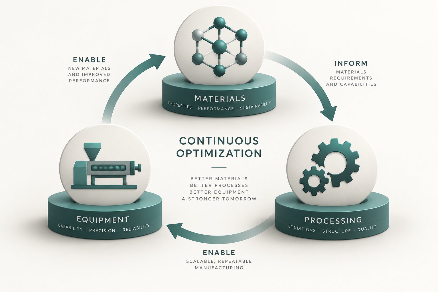
Materials, parameters, and hardware—every section of this article has treated one of these three domains in relative isolation. Real compounding operations, however, never afford that luxury. A change in filler type ripples through your temperature profile, your screw configuration, and your SME target simultaneously. A worn kneading block shifts your dispersive threshold, which forces you to compensate with higher screw speed, which raises melt temperature, which narrows your thermal safety margin. The interactions are circular, not linear, and optimizing one domain while ignoring the other two is the single most common reason melt mixing operations plateau below their potential.
What process engineers need is not another list of isolated tips but a unified framework that ties materials, parameters, and equipment into a coherent decision loop. The structure below provides exactly that.
The Three Pillars of Melt Mixing Optimization
Every successful compounding operation rests on three interdependent pillars. Imagine them as the legs of a tripod: remove one, and the whole system collapses.
Pillar 1 — Material Selection. This is where the process begins, long before anyone touches a barrel heater. Which base polymer are you using, and what are its melt viscosity, crystallinity, and degradation ceiling? What filler system are you incorporating—mineral, glass fiber, nanofiller—and at what loading? Does the filler-polymer interface require a compatibilizer like MAH-g-PP, a silane coupling agent, or a reactive masterbatch? Each of these choices defines the rheological landscape your extruder must navigate. A high-viscosity nylon filled with 30% glass fiber presents a fundamentally different challenge than a low-viscosity PP blended with 3% organoclay, even if both run on the same machine.
Pillar 2 — Processing Parameters. Temperature profile, screw speed, feed rate, back-pressure, and their integrative metric—specific mechanical energy—form the operational envelope. These are your real-time control levers, the variables you adjust shift by shift to keep compound quality on target. Yet every lever has limits set by Pillar 1: you cannot push barrel temperature above the degradation ceiling of your resin, and you cannot raise screw speed beyond the torque capacity of your drive without reducing feed rate.
Pillar 3 — Equipment Configuration. Screw element layout, barrel zone design, vent-port placement, and die restriction define the physical pathway through which material and energy interact. Research on twin-screw compounding confirms that screw configuration and barrel geometry are the structural backbone of the process—they determine residence time distribution, shear history, and whether each functional zone (melting, mixing, venting, pressure build-up) operates as designed.
Successful melt mixing requires simultaneous optimization across all three pillars—material selection, processing parameters, and equipment configuration—because changing one variable cascades into required adjustments in the other two.
Consider a concrete scenario. You are compounding a PP-based nanocomposite and your materials team switches from a standard montmorillonite clay to a higher-aspect-ratio graphene nanoplatelet. That single change in Pillar 1 triggers a cascade: the new filler increases melt viscosity at equivalent loading (Pillar 2 must respond with adjusted temperature and possibly reduced feed rate), demands higher dispersive shear to overcome stronger van der Waals adhesion (Pillar 3 may require wider kneading blocks or an additional mixing section), and generates fewer volatiles than organomodified clay (Pillar 3 vent-zone design can potentially be simplified). Treating the filler swap as a drop-in substitution—without revisiting parameters and screw layout—virtually guarantees underdispersed product.
This three-pillar logic also explains why copying a competitor's published processing conditions rarely works. Their material grades, screw element inventory, and barrel geometry differ from yours. The only transferable metric is SME, and even that requires validation against your specific residence time distribution and thermal profile. Much like how a gerber mixed berry yogurt melts product depends on precise ingredient ratios, processing temperatures, and equipment calibration working together to deliver consistent texture in every piece, your compound depends on all three pillars aligning to deliver consistent morphology in every pellet.
Practitioner Checklist for Process Development
Frameworks are useful, but engineers need actionable steps. The following checklist distills the three-pillar approach into a practical sequence you can follow from first trial to stable production:
- Characterize raw material rheology and thermal behavior. Before running a single extrusion trial, measure or obtain melt viscosity curves (ideally Carreau-Yasuda fits), DSC data for melting point and glass transition, TGA data for degradation onset, and MFI for quick benchmarking. These numbers define your processing window boundaries.
- Define the target morphology or dispersion state. What does "good" look like for your compound? For a polymer blend, the target might be a sub-micron dispersed-phase domain size. For a nanocomposite, it might be full exfoliation confirmed by XRD or TEM. For a color masterbatch, it might be a maximum acceptable delta-E. Without a quantitative target, optimization has no finish line.
- Select a screw configuration to deliver the required dispersive and distributive mixing. Map your functional zones—solids conveying, melting, primary mixing, secondary mixing, venting, pressure build-up—and assign element types and stagger angles to each. Use the dispersive-versus-distributive comparison table from earlier sections as a guide. If your formulation includes abrasive fillers, specify wear-resistant metallurgy for high-shear elements from the outset.
- Set initial processing parameters based on material data. Start with barrel temperatures 10-20 °C above the melting point of your highest-Tm component, a moderate screw speed (50-70% of maximum), and a feed rate that fills kneading zones without flooding vent ports. These starting points are not final answers—they are educated first guesses anchored in Pillar 1 data.
- Measure SME and product quality. Record motor torque and throughput to calculate SME for each trial. Simultaneously evaluate compound quality against your Step 2 targets—microscopy for morphology, mechanical testing for property verification, visual inspection for surface defects. Optimization studies in polymer processing consistently show that tracking multiple performance measures simultaneously prevents single-objective traps where improving one property inadvertently degrades another.
- Iterate configuration and parameters toward targets. If dispersive mixing is insufficient (visible agglomerates survive), add wider kneading blocks or increase screw speed. If distributive mixing is lacking (composition gradients or color streaks), introduce toothed mixing elements or extend the distributive zone. If melt temperature exceeds the degradation ceiling, reduce screw speed and compensate with higher barrel temperature or longer mixing sections. Each adjustment loops back through all three pillars, so re-measure SME and quality after every change.
This iterative loop—adjust, measure, compare, repeat—is the same logic that multi-objective optimization algorithms apply computationally, evolving a population of solutions toward a Pareto front where no single objective can be improved without trading off another. You are doing the same thing manually, guided by data rather than intuition. Over time, the data you accumulate builds an internal knowledge base that accelerates future development cycles and reduces the number of iterations needed for new formulations.
Continuous Improvement Through Configuration and Component Selection
Optimization is not a one-time event. Formulations evolve as raw material suppliers change grades, as recycled content percentages climb, and as end-use specifications tighten. Screw elements wear. Barrel liners thin. What ran perfectly last quarter may drift out of specification this quarter without any deliberate change on your part.
The modular architecture of twin-screw extruders is purpose-built for this reality. Instead of replacing an entire screw shaft every time the process demands a tweak, you swap individual segments—adding a kneading block here, extending a conveying section there, replacing a worn dispersive element with a fresh one. That modularity turns Pillar 3 into a living, adjustable system rather than a fixed constraint.
Where twin-screw configuration is the optimization lever, component suppliers such as NANHAIYA provide modular screw elements and kneading blocks that let engineers adjust conveying, mixing, dispersion, and venting zones without replacing entire screws. By reviewing element geometry, shaft matching, filler content, and current wear conditions, such suppliers help processors translate the three-pillar framework into physical hardware changes—closing the loop between what the process needs and what the equipment delivers.
A few guiding principles keep the continuous-improvement cycle productive rather than chaotic:
- Change one variable at a time when troubleshooting. Simultaneous changes in screw layout and processing parameters make it impossible to attribute cause and effect.
- Benchmark every configuration change against SME and product quality. If the new layout does not move the needle on at least one measurable outcome, revert and investigate further before trying another modification.
- Schedule wear inspections at fixed intervals tied to throughput tonnage, not calendar time. A line running 24/7 with 40% glass fiber accumulates wear far faster than one running intermittent batches of unfilled resin.
- Document screw element maps for every validated configuration. When a process drifts, the first diagnostic step is confirming that the physical element layout still matches the documented map. Missing or swapped segments are a surprisingly common root cause of unexplained quality shifts.
Melt mixing remains the most industrially scalable, solvent-free route for producing polymer blends, compounds, and nanocomposites. From molecular-level compatibilization strategies to macro-level decisions about kneading block width and stagger angle, the depth of engineering choices offers continuous room for improvement. The processors who outperform their peers are not the ones with the biggest extruders or the newest controls—they are the ones who treat materials, parameters, and equipment as a single, interconnected system and iterate relentlessly until all three pillars are aligned.
Frequently Asked Questions About Melt Mixing
1. What is the difference between melt mixing, melt blending, and melt compounding?
All three terms describe combining materials in the molten state under mechanical shear, and they are often used interchangeably. However, subtle distinctions exist. Melt compounding typically refers to incorporating fillers, reinforcements, or functional additives into a polymer matrix. Melt blending usually describes polymer-polymer systems without particulate fillers. Melt mixing is the broadest umbrella term that covers both scenarios. In practice, the context of the formulation—whether it involves fillers or only polymers—determines which term is most precise.
2. Why is a twin-screw extruder preferred over a single-screw extruder for melt mixing?
Co-rotating twin-screw extruders transfer the full channel contents from one screw to the other repeatedly, delivering intensive mixing with far less pressure drop per mixing event than a single-screw design. Their modular architecture allows engineers to assemble interchangeable conveying elements, kneading blocks, and mixing segments in a customized sequence, creating distinct functional zones for melting, mixing, venting, and pressure build-up. Single-screw extruders rely on drag flow, which limits radial turnover and restricts mixing intensity. While single-screw machines remain efficient for simple melting and forming tasks, any operation requiring filler dispersion, immiscible polymer blending, or reactive compounding benefits from the twin-screw platform's superior mixing control.
3. What is specific mechanical energy (SME) and why does it matter for scale-up?
Specific mechanical energy is the total mechanical energy the motor transfers through the screws into each kilogram of compound, expressed in kWh/kg. It integrates screw speed, torque, and throughput into one number, making it the most reliable metric for comparing processing conditions across different machine sizes. During scale-up, matching SME between a lab extruder and a production line is a necessary condition for matching product quality. Case studies have shown that failing to match SME—sometimes by as much as 69%—can result in unmolten pellets and completely unusable product, even when screw design and temperature profiles appear identical.
4. How do you achieve good nanofiller dispersion through melt mixing?
Effective nanofiller dispersion requires balancing high enough shear stress to break agglomerates without degrading the polymer matrix or fracturing the fillers themselves. Key strategies include using compatibilizers such as maleic anhydride grafted polyolefins or silane coupling agents to lower the interfacial energy between filler and matrix, configuring screw elements with dedicated high-shear dispersive zones followed by gentler distributive sections, and employing a masterbatch dilution approach where a high-loading concentrate is first produced under aggressive conditions and then let down into the final resin on a second pass. Screw element suppliers like NANHAIYA (https://www.nhyscrews.com/products/segment-screw) can help processors select kneading block geometries suited to specific nanofiller types and loading levels.
5. How often should twin-screw extruder screw elements be inspected and replaced?
Inspection intervals should be tied to cumulative throughput tonnage rather than calendar time, because wear rates vary enormously depending on filler type, loading, and processing temperature. Lines running abrasive fillers like glass fiber or calcium carbonate at high loadings may need flight-tip diameter measurements every few hundred hours. Key indicators of element wear include declining torque at constant conditions, visible agglomerates in previously clean compounds, and widening clearances measured during scheduled shutdowns. Replacing worn kneading blocks and conveying elements with geometry-matched, wear-resistant replacements restores dispersive and distributive mixing performance and prevents the slow, often invisible quality drift that worn hardware causes.
Written by
Nanhaiya Technical Team
Zhoushan Nanhaiya Plastic Machinery Co., Ltd.
The Nanhaiya technical team supports screw and barrel manufacturing projects through application review, technical communication, custom manufacturing coordination, and production and quality control.
Discuss Your Application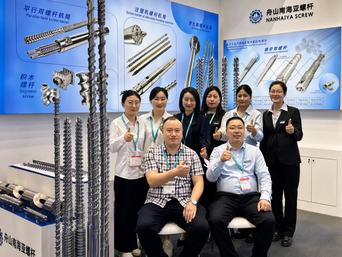
Related Articles
More insights on screw barrel technology and plastics processing.
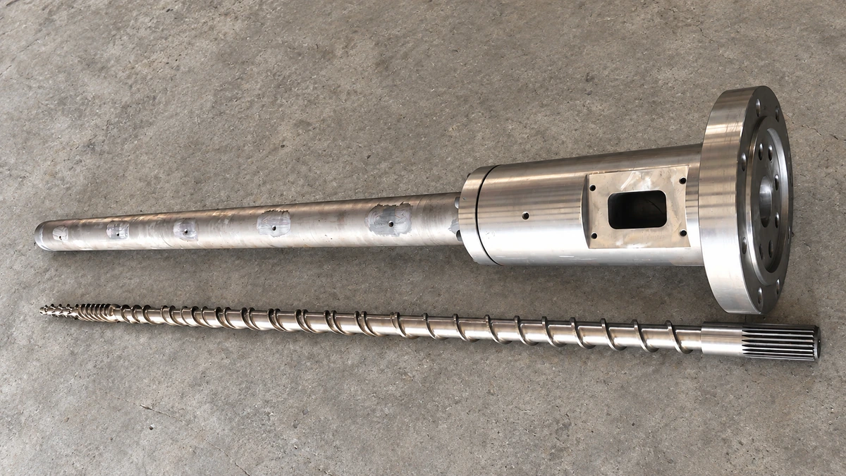
Why Your Single Screw Extruder Design Causes Extrusion Defects
Nov 13, 2026
Learn how single screw extruder design parameters—L/D ratio, compression ratio, channel depth, and mixing elements—affect melt quality, throughput, and defects.
Read Article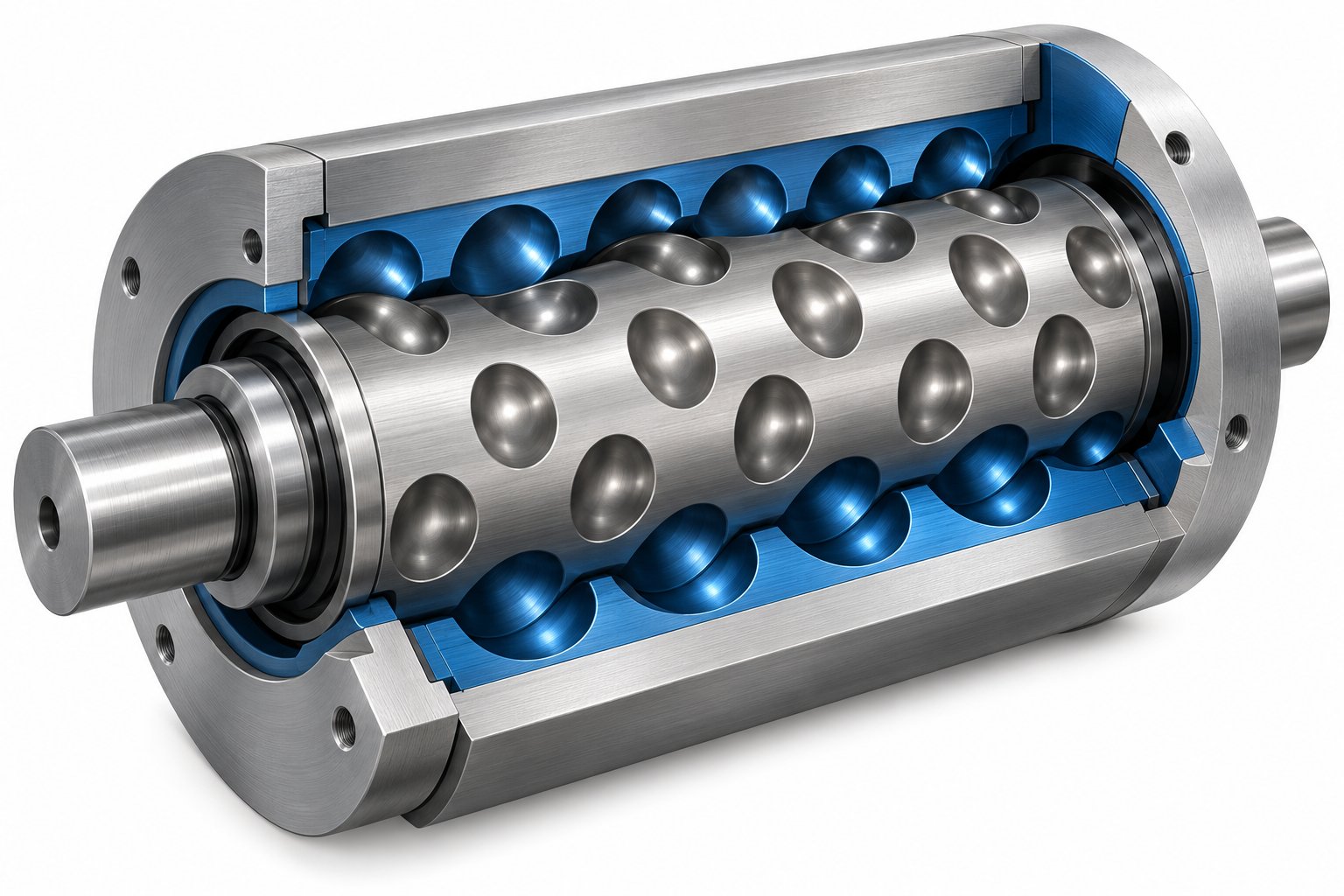
Cavity Transfer Mixer: The Blender Your Extruder Didn't Know It Needed
Nov 13, 2026
Learn how a cavity transfer mixer (CTM) upgrades single-screw extruder mixing. Covers working principles, key parameters, integration, applications, and comparisons.
Read Article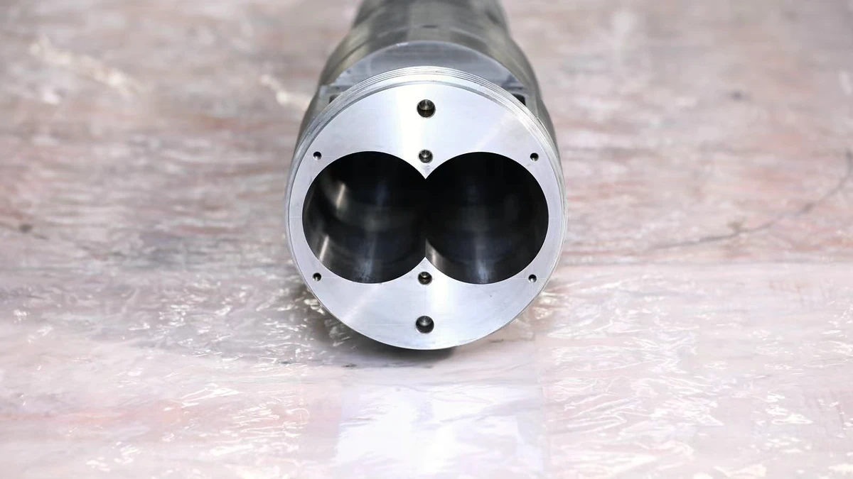
Extruder Barrel Alignment Decoded: Tolerances Most Plants Miss
Nov 13, 2026
Learn extruder barrel alignment tolerances, laser procedures, thermal offsets, and proactive schedules most plants miss — for single-screw and twin-screw lines.
Read ArticleLooking for something else?
Search by material, symptom or product and jump straight to the relevant page.
These are navigation suggestions based on keyword matching — not a quotation, not a delivery commitment, and not a substitute for engineering review. Final specification is confirmed by our engineers against your drawings and processed material.
Need help with screw barrel selection?
Share your machine model, processed material and application. Our team can help with pricing and technical support.