

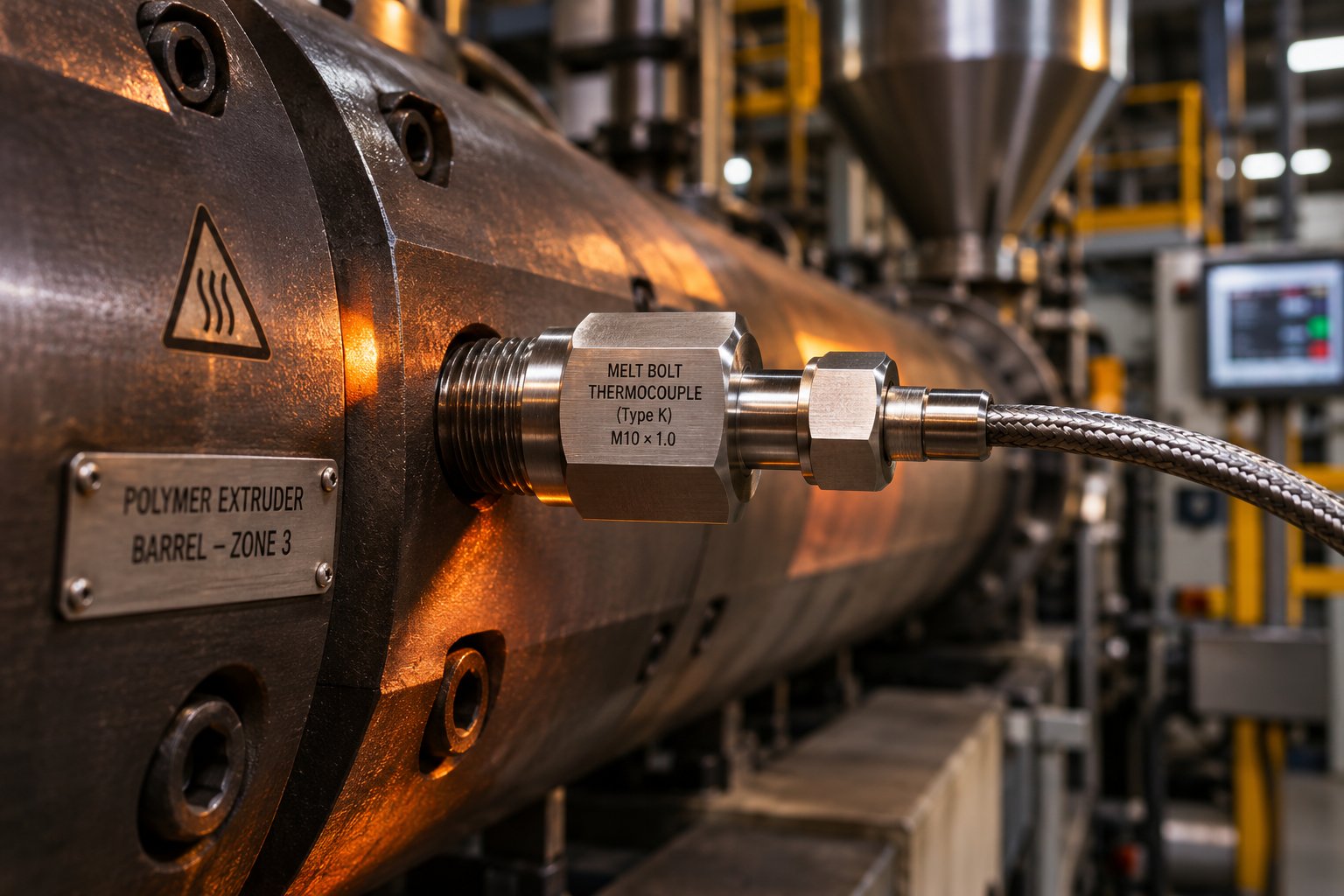
What Is a Melt Thermocouple and Why It Matters
A melt thermocouple is a temperature sensor whose sensing tip is immersed directly in molten polymer inside an extruder or injection molding barrel. Unlike standard barrel-mounted sensors that read the temperature of the surrounding steel, this probe contacts the flowing plastic itself, delivering a true measurement of what the material actually experiences before it exits the die or fills a mold.
That distinction sounds subtle, but the consequences are anything but. When you rely solely on a barrel-wall reading, you're measuring metal — not plastic. And because molten polymers are extraordinarily poor conductors of heat (roughly 70 to 200 times less conductive than the steel around them, as research from Dow's Mark Spalding demonstrates), the temperature at the barrel surface can differ dramatically from the temperature at the center of the melt channel.
A melt thermocouple measures the temperature of the polymer stream itself, providing data that barrel-surface sensors cannot replicate.
Defining the Melt Thermocouple
Picture a sheathed thermocouple element — typically stainless steel or Inconel — threaded into a tapped port on the barrel wall through a compression fitting or a melt bolt. The critical detail? Its tip protrudes past the steel and into the melt channel, making direct contact with flowing resin. Fixed melt bolt thermocouples are the most common version: a rugged, threaded bolt housing the sensor element, designed to withstand process pressures that can exceed 10,000 psi in injection molding. The sensing junction sits at the end of the probe, right in the polymer stream, converting the heat it absorbs into a small millivolt signal that your controller reads as temperature.
This design contrasts sharply with a barrel-zone thermocouple, which sits flush against (or embedded within) the barrel wall. That sensor tells you what the steel is doing — useful information, certainly, but not a direct reflection of what the polymer feels as it moves through the channel.
Why Barrel Temperature Alone Falls Short
Imagine setting your barrel zones to 220 °C and assuming the polymer exits at 220 °C. In reality, shear heating from the rotating screw can push the melt well above the barrel setpoint, while residence-time effects and cooling zones create gradients across the channel. Experimental data from single-screw extrusion studies shows that the actual temperature profile across a transfer-line cross-section is parabolic: cooler near the barrel wall, significantly hotter at the center. In one documented test, a flush-mount sensor read 198 °C while the bulk melt was closer to 233 °C — a gap of 35 degrees that would wreck any quality-sensitive process.
Extrusion expert Jim Frankland reinforces this point: barrel temperatures have a surprisingly small effect on actual melt temperature because polymers are excellent insulators and residence time is short. The screw's mechanical energy — not the barrel heaters — dominates the temperature the resin reaches. Adjusting barrel setpoints without monitoring the melt directly is, in many cases, guesswork.
This is exactly why a properly installed melt thermocouple transforms temperature data from an approximation into a genuine process variable. Whether you're running a single-screw extruder, a twin-screw compounding line, or an injection molding cell, the probe gives you the number that actually correlates with part quality, fill behavior, and material integrity.
The sections ahead walk through every stage of getting that number right — from sensor construction and thermocouple type selection, through installation depth and signal wiring, all the way to calibration, troubleshooting, and sourcing replacements when a probe reaches end of life.
How Melt Thermocouples Work and What They Are Made Of
Every melt thermocouple — regardless of brand, bolt size, or mounting style — operates on a single physical phenomenon discovered in the early 1800s: the Seebeck effect. Two wires made from dissimilar metal alloys are joined at one end to form a sensing junction. When that junction is heated by the surrounding polymer melt, it generates a tiny voltage — typically just a few millivolts — proportional to the temperature difference between the hot junction immersed in the plastic and a cold-junction reference point back at the controller terminal. Your temperature display, PLC, or data logger interprets that millivolt signal and converts it into a readable temperature value.
Sounds straightforward? The physics are simple. The engineering challenge, however, is keeping that delicate sensing junction alive and accurate inside an environment that combines extreme pressure, corrosive chemical byproducts, and abrasive filler materials — all simultaneously.
Thermocouple Construction for Melt Environments
A standard laboratory thermocouple would fail within hours inside a plasticating barrel. Melt thermocouples are purpose-built to survive conditions that routinely exceed 10,000 psi in injection molding and involve direct contact with chemically aggressive polymer melts. The construction that makes this possible is mineral-insulated (MI) cable technology — the same architecture trusted in petrochemical reactors and aerospace engine testing.
Inside the probe, two thermocouple wires run through tightly compacted magnesium oxide (MgO) powder. This mineral insulation serves a dual purpose: it prevents the wires from shorting against each other or against the outer sheath, and it transfers heat efficiently from the sheath wall to the sensing junction. The entire assembly is encased in a seamless metal sheath — most commonly 304 or 316 stainless steel for general polymer processing, or Inconel 600 when corrosive resins like PVC, fluoropolymers, or flame-retardant compounds are involved. Inconel's nickel-chromium composition resists the hydrochloric acid and hydrofluoric acid vapors these materials can release at processing temperatures.
The sheath, wires, and insulation are then swaged (drawn down) into a compact, pressure-tight cable that can be bent, trimmed, and terminated without losing functionality. For a 5/16 melt bolt thermocouple — one of the most common form factors in extrusion — this MI cable is housed inside a threaded bolt body with a sealing washer and a connection head or lead wire at the opposite end.
One critical construction detail that directly affects your readings is the junction style:
- Grounded junction — The thermocouple wires are welded directly to the inside of the sheath tip. Heat transfers rapidly from the melt through the sheath wall to the junction, producing a faster response time. The tradeoff? The sensing circuit is electrically connected to the sheath, making it vulnerable to ground loops and electromagnetic noise from barrel-band heaters and variable-frequency drives.
- Ungrounded junction — The weld bead is electrically isolated from the sheath by the MgO insulation. Response time is slightly slower because heat must conduct through the insulation layer before reaching the junction, but the sensor gains immunity to electrical noise and stray currents — a significant advantage on machines with multiple heater zones and VFDs.
For most polymer processing environments, ungrounded junctions are the safer default choice because electrical noise is nearly universal on production floors. Grounded versions make sense when response speed is the overriding priority and proper signal shielding is already in place.
Here are the key construction elements you should evaluate when specifying or inspecting any melt thermocouple:
- Sheath material — Stainless steel for standard resins; Inconel for corrosive or halogenated polymers
- Thermocouple wire type — Determines temperature range and accuracy (covered in the next section)
- Mineral insulation — Compacted MgO for electrical isolation and thermal conductivity
- Junction style — Grounded for speed, ungrounded for noise immunity
- Mounting hardware — Bolt thread size, sealing washer, and connection head or lead-wire termination
Thermocouple Types and Their Temperature Limits
The "type" designation on a thermocouple — Type J, Type K, Type N, and so on — refers to the specific pair of metal alloys that form the sensing wires. Each combination produces a different voltage-versus-temperature curve, which means each has a different usable range, accuracy profile, and set of environmental sensitivities. In polymer melt measurement, three types dominate.
Type J (Iron / Constantan) pairs an iron positive wire with a copper-nickel alloy negative wire. It operates from -210 °C up to about 760 °C and produces a relatively high millivolt output per degree, making it slightly more sensitive than Type K. Many legacy extrusion and injection molding machines — and a large share of Dynisco melt thermocouples — ship with Type J calibration. The limitation? The iron conductor is susceptible to oxidation at elevated temperatures, which shortens service life and accelerates drift when the sensor operates near the upper end of its range for extended periods.
Type K (Chromel / Alumel) uses a nickel-chromium positive wire and a nickel-aluminum negative wire. Its usable range extends from -200 °C to approximately 1,260 °C — far beyond what any commodity or engineering polymer requires. This broader headroom means the wires experience less metallurgical stress at typical plastics processing temperatures (generally 150 °C to 400 °C), which translates to slower drift and longer probe life compared to Type J in the same application. Type K is the most widely used thermocouple calibration worldwide and is the go-to choice for new melt-monitoring installations.
You might wonder: can the thermocouple wire itself melt during polymer processing? The melting point of Type K thermocouple wire — specifically, the chromel and alumel alloys — sits well above 1,400 °C, far beyond any plastics processing temperature. Wire integrity is never the limiting factor. What does limit lifespan is gradual metallurgical change: prolonged exposure to temperatures in the 343 °C to 593 °C range can cause "atomic ordering" in the positive leg of Type K wire, producing a cumulative positive drift in readings over weeks or months.
Type N (Nicrosil / Nisil) was developed specifically to address the drift and oxidation weaknesses of Type K. Its nickel-chromium-silicon and nickel-silicon alloy wires offer improved stability and resistance to oxidation at high temperatures, making it an excellent upgrade path for processors running engineering resins (PEEK, PEI, PPS) where barrel temperatures approach 400 °C and long-term accuracy matters. The tradeoff is a slightly lower millivolt output and higher cost per probe.
Exotic thermocouple types — such as tungsten-rhenium (Type C) — are designed for extreme environments like melting furnaces and vacuum metallurgy, where temperatures exceed 2,000 °C. They have no practical role in plastics processing and are mentioned here only because they occasionally appear in searches for "thermocouple melting points."
The table below provides a quick-reference comparison for the three types most relevant to polymer melt measurement:
| Characteristic | Type J (Iron / Constantan) | Type K (Chromel / Alumel) | Type N (Nicrosil / Nisil) |
|---|---|---|---|
| Usable Temperature Range | -210 °C to 760 °C | -200 °C to 1,260 °C | -270 °C to 1,300 °C |
| Standard Accuracy (Class 1) | ±1.5 °C or ±0.4% | ±1.5 °C or ±0.4% | ±1.5 °C or ±0.4% |
| Drift Susceptibility | Moderate — iron leg oxidizes at high temps | Moderate — atomic ordering in 343-593 °C range | Low — designed for improved long-term stability |
| Polymer-Processing Suitability | Good for commodity resins up to ~400 °C; common on legacy machines | Excellent general-purpose choice; widest installed base | Best for high-temp engineering resins and quality-critical processes |
| Relative Cost | Low | Low to moderate | Moderate to high |
Choosing between these types is often straightforward: match the thermocouple calibration to what your controller expects (swapping from J to K requires reconfiguring the input), and select the type whose drift characteristics and environmental resistance best fit your resin portfolio and maintenance schedule. For a retractable melt bolt thermocouple that will be inspected and swapped regularly, Type J may be perfectly adequate. For a fixed probe in a continuous compounding line running glass-filled nylon at 290 °C around the clock, Type K or Type N is the smarter long-term investment.
Construction and type selection get the right sensor into the barrel. The next question — and the one that separates a textbook choice from a real-world solution — is which physical mounting style puts the sensing junction exactly where it needs to be relative to the flowing polymer.
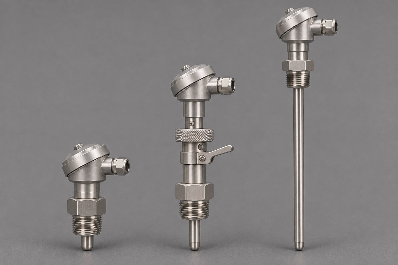
Types of Melt Thermocouples From Fixed Bolt to Retractable
Mounting style determines far more than how a melt thermocouple attaches to your barrel. It dictates whether you can adjust immersion depth after startup, whether you can service the probe without shutting down the line, and whether your sensing junction lands in the right zone of the polymer stream for your specific process. Picking the wrong configuration means either living with a compromise or pulling the machine offline to make a change — neither of which is appealing during a production run.
Three broad categories cover the vast majority of polymer processing installations: fixed bolt designs, retractable bolt designs, and immersion or variable-depth probes. Each serves a distinct operational need, and understanding their differences prevents the kind of mismatch that turns a reliable sensor into a source of misleading data.
Fixed Melt Bolt Thermocouples
If you've worked on an extruder or injection molding barrel, you've almost certainly handled one of these. A fixed melt bolt thermocouple houses a mineral-insulated sensing element inside a threaded bolt — typically 1/2"-20 UNF, though M18x1.5 and other thread sizes are common depending on the machine origin. The bolt screws into a tapped port on the barrel or adapter, and the sensing tip protrudes a factory-set distance into the melt channel. That distance cannot be adjusted after installation.
Why is this the most widely used configuration? Simplicity and durability. There are no moving parts, no adjustment mechanisms, and no sliding seals to maintain. The 304 stainless steel construction (with optional Inconel 600 or Hastelloy for aggressive resins) handles process pressures and temperatures across the full range of commodity and engineering polymers. Immersion lengths typically range from flush mount to about 1 inch (25 mm), and junction types include both grounded and ungrounded options.
The fixed design shines in stable, well-characterized processes where the optimal immersion depth is already known. Once installed and torqued to spec, it delivers consistent, repeatable readings shift after shift with virtually zero operator intervention. Cost per unit is the lowest of any melt-probe configuration, making it practical to install multiple units along a barrel or at every adapter and die location.
The limitation is equally straightforward: if you need a different immersion depth — because you've changed barrel diameters, switched to a screw design that alters the melt-channel geometry, or discovered that your current depth reads too close to the wall — you'll need to replace the probe entirely with one built to a different tip length.
Retractable Melt Bolt Thermocouples
Imagine running a continuous extrusion line 24/7 and needing to inspect or replace a temperature sensor without depressurizing the barrel. A retractable melt bolt thermocouple makes that possible. The probe slides within a pressure-rated housing, allowing the operator to withdraw the sensing tip from the melt stream while a sealing mechanism keeps molten polymer from escaping through the port.
This design is a major advantage for continuous extrusion and compounding operations where unplanned downtime is measured in thousands of dollars per hour. Instead of scheduling a full shutdown to swap a suspect sensor, maintenance can retract the probe, inspect the tip for degradation or polymer buildup, clean or replace it, and re-insert — all while the screw keeps turning.
Beyond serviceability, retractable designs offer an adjustable-depth feature that fixed bolts cannot match. The probe's insertion depth can be varied to optimize the sensing junction's position within the melt channel. This is particularly valuable when running different barrel sizes on the same line or when you want to verify that your reading truly represents flowing polymer rather than a boundary layer influenced by barrel-wall temperature. Some retractable melt thermocouples feature graduated markings on the stem, letting you log the exact immersion depth for each process setup and reproduce it after maintenance — a detail that the ICS Schneider engineering team rightly emphasizes as essential for traceable measurements.
The tradeoff? Retractable probes cost more than fixed bolts, and the sliding seal is an additional wear component that requires periodic inspection. In high-pressure injection molding applications, verifying the seal's pressure rating against actual process conditions is critical before specifying this style.
Immersion and Variable-Depth Probes
Some processes demand more than a single-point temperature reading. When you need to understand the radial temperature profile across the melt channel — from the barrel wall all the way to the center — a variable-depth probe is the right tool. These sensors allow operators to progressively move the sensing tip from a flush position deeper into the polymer flow, recording temperatures at multiple immersion depths to build a cross-sectional profile.
Why does that profile matter? Because the melt stream is rarely isothermal. Experimental work on single-screw extruders has documented parabolic temperature distributions where the core of the stream runs significantly hotter than the region near the wall. A variable-depth probe reveals this gradient directly, letting you determine exactly where in the channel your fixed production sensor should sit for the most representative reading.
Immersion melt thermocouples — including plastic immersion types designed for full melt-stream contact — extend this concept further. Their longer probes reach well past the boundary layer, providing measurements from deep within the flowing polymer. This makes them especially useful during process development, material trials, or troubleshooting situations where you suspect that shear heating or insufficient mixing is creating hidden temperature variations.
In injection molding, a related category deserves mention: combined melt pressure sensors with integrated thermocouples. An injection molding melt pressure sensor with thermocouple gives you both cavity or nozzle pressure and temperature from a single port, reducing the number of barrel penetrations while providing correlated data for scientific molding practices. These transducers are particularly common in nozzle positions, where capturing temperature just before injection or die entry helps verify that the polymer meets quality specifications at the exact moment it matters most.
Nozzle melt thermocouples — whether standalone or integrated into a pressure transducer — represent a special subcategory. Installed at the machine nozzle tip, they capture the final melt temperature after all barrel zones, screw work, and back-pressure effects have had their influence. For processors practicing scientific molding or running tight-tolerance medical and automotive parts, a nozzle reading often correlates more strongly with part quality than any upstream barrel measurement.
The table below summarizes how these three primary configurations compare across the factors that matter most when choosing a melt thermocouple style:
| Feature | Fixed Melt Bolt | Retractable Melt Bolt | Variable-Depth / Immersion Probe |
|---|---|---|---|
| Adjustability | None — tip depth is set at manufacture | Adjustable during operation via sliding mechanism | Fully adjustable; designed for profiling at multiple depths |
| Replacement Ease | Requires depressurizing and removing the bolt | Probe can be retracted and serviced without full shutdown | Varies by design; some require depressurization |
| Relative Cost | Low | Moderate to high | Moderate to high |
| Best-Fit Application | Stable production lines with known immersion requirements | Continuous extrusion and compounding needing live serviceability | Process development, troubleshooting, and radial temperature profiling |
Selecting the right mounting style is only half the equation. Each of these probe types can be installed in a barrel zone, an adapter flange, a die inlet, or a nozzle tip — and the location you choose determines what the sensor actually tells you about your process. The differences between those installation points, and the processing methods that benefit most from each, shape how melt temperature data translates into real product quality.
Melt Thermocouple Applications Across Polymer Processing
Most guides on melt temperature measurement focus almost exclusively on single-screw extrusion — and for good reason, since that's the most common platform. But polymers travel through many types of machines before they become finished parts, and the physics of heat transfer and shear don't change just because the equipment does. Every process that pushes molten plastic through a confined channel benefits from knowing the true melt temperature thermocouple data, not just the barrel-zone setpoint glowing on a controller screen.
Where you place the sensor — and which process you're running — determines the kind of insight you gain. A single melt thermocouple at the adapter tells one story. Sensors at multiple strategic points along the barrel, die, and nozzle tell a much richer one.
Extrusion and Compounding Applications
In single-screw extrusion, installing probes at the adapter between the barrel and the die is the most common starting point. That location captures the cumulative thermal history of the polymer after it has passed through every barrel zone and experienced the full effect of screw-driven shear heating. But a single adapter reading doesn't reveal where along the barrel things started going wrong. Adding sensors at intermediate barrel positions and at the die inlet builds a temperature profile that exposes localized hot spots, confirms whether the screw design is delivering the expected thermal behavior, and flags when shear heating is exceeding acceptable limits.
Twin-screw compounding raises the stakes considerably. Corotating intermeshing twin-screw extruders are among the most aggressive energy-input devices in polymer processing — the motor, not the barrel heaters, dominates how much energy the material absorbs. Research conducted on Leistritz ZSE-27 twin-screw extruders demonstrated that aggressive melting-zone screw configurations produced melt temperatures 10 to 30 degrees Celsius higher than extended melting-zone designs — and that an immersion probe recorded temperatures 20 to over 40 degrees Celsius above what a flush-mount sensor showed at the same location. The takeaway is stark: without a properly immersed melt thermocouple, a compounder running an aggressive screw design may never realize how much thermal damage the formulation is absorbing.
That same Leistritz study revealed another practical detail. Higher melt temperatures from aggressive screw designs led to visible degradation — smoke and discoloration — at elevated screw speeds, along with lower attainable throughput rates. Processors who relied only on barrel-zone readings would miss the early stages of that degradation entirely, because the metal temperature doesn't reflect the energy the screw is dumping directly into the polymer. Monitoring the actual melt stream transforms temperature from a passive display value into an actionable process control variable.
Injection Molding Melt Monitoring
Injection molding introduces a different set of challenges. The process is cyclic rather than continuous, melt pressures spike during injection, and the thermal state of the polymer at the moment it enters the mold cavity directly determines fill behavior, crystallization rate, and final part dimensions. A few degrees of melt temperature variation can shift the viscosity enough to cause short shots on one cycle and flash on the next.
Melt thermocouples in injection molding are typically installed at the nozzle or in the barrel near the front zone, where they capture the polymer's temperature just before it enters the mold. Combined pressure-temperature transducers — an injection molding melt pressure sensor with thermocouple built into a single housing — are especially popular in this setting because they deliver correlated pressure and temperature data from a single barrel penetration. That pairing supports scientific molding practices, where processors use sensor data to set the velocity-to-pressure (V/P) switchover point, optimize packing pressure, and verify cycle-to-cycle consistency.
A study published in the journal Technologies demonstrated what happens when nozzle-mounted pressure sensing is combined with rigorous parameter optimization. Researchers used a nozzle pressure sensor to define online quality characteristic values — peak pressure, relative viscosity, and a viscosity index — and then fed those values into an adaptive process control system. The result was a reduction in product weight standard deviation to as low as 0.0148 grams and a coefficient of variation of just 0.035%. While that study focused on pressure rather than temperature, the principle reinforces why capturing real data at the nozzle matters: it's the last point where you can detect and correct deviations before the polymer is locked into its final shape.
For processors running tight-tolerance automotive or medical parts, a nozzle melt thermocouple reading often correlates more strongly with part quality than any upstream barrel measurement, because it reflects the true thermal state of the material after all screw work, back-pressure effects, and zone-to-zone variations have played out.
Blow Molding and Film Extrusion
Blow molding and film extrusion share a common sensitivity: wall-thickness uniformity. In blow molding, the parison (or preform) must exit the die head at a consistent temperature around its entire circumference and along its length. Even small thermal gradients cause some sections to stretch more than others during inflation, producing thin spots that become structural weak points in the finished container. As engineering resources on blow molding uniformity emphasize, hot spots in the die cause thinner walls in those areas, while cooler zones restrict stretching and create heavy sections.
A melt thermocouple installed at the die inlet or parison head catches these thermal variations before they reach the mold. Processors who monitor melt temperature at this location can distinguish between a uniformity problem caused by die geometry and one caused by an upstream temperature excursion — a distinction that barrel-zone readings alone simply cannot make.
Blown film extrusion follows the same logic. The annular die must deliver polymer at a uniform temperature to produce film with consistent gauge and optical clarity. Temperature deviations as small as 2 to 3 degrees Celsius can show up as haze bands or thickness rings in the finished film. Placing a melt thermocouple at the die inlet gives operators a direct measurement they can correlate with film quality data, closing the loop between machine settings and product performance.
Across all of these processes, the core message is the same: barrel-zone thermocouples are standard on every machine, but they measure steel. Adding dedicated probes at strategic locations transforms your temperature data from an approximation into a true process variable. The key insertion points span the entire flow path:
- Barrel zones — Intermediate positions along the plasticating section to detect localized shear heating
- Adapter — Between barrel and die, capturing cumulative melt temperature after all screw work
- Die inlet — The final check before polymer enters the shaping tool
- Nozzle tip — Critical for injection molding, where the reading reflects the exact thermal state entering the mold cavity
- Parison head — Essential in blow molding for wall-thickness control and uniformity monitoring
Knowing where to place a sensor is one thing. Getting it seated correctly — at the right depth, with the right seal, and without introducing the very errors you're trying to eliminate — is where many installations quietly go wrong. The details of immersion depth, orientation, and torque make the difference between a melt thermocouple that delivers trustworthy data and one that reads little better than the barrel sensor it was meant to replace.
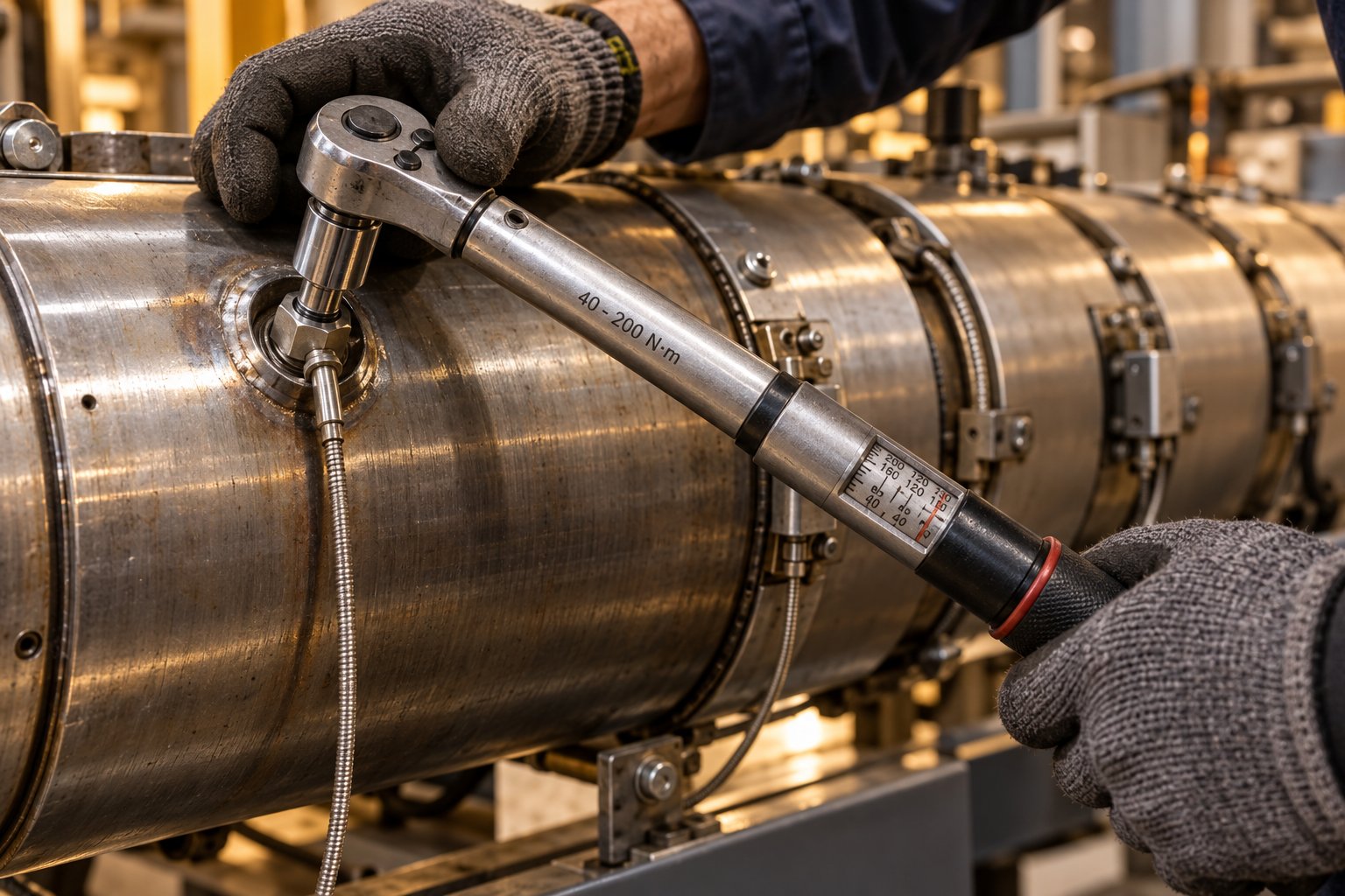
Installation Best Practices for Reliable Melt Readings
You've selected the right thermocouple type, chosen between fixed and retractable mounting, and identified the ideal location on your barrel or adapter. Everything looks good on paper. Yet a surprising number of melt thermocouple installations deliver readings that are no more useful — and sometimes less accurate — than a simple barrel-surface sensor. The reason almost always traces back to how the probe was physically installed: too shallow, too deep, improperly sealed, or wired through a noisy cable tray. Getting the hardware right is where theory meets reality.
Choosing the Right Immersion Depth
Immersion depth is the single most influential installation parameter. It determines whether your sensing junction contacts flowing polymer or simply reads the thermal environment of the barrel wall and measuring bore. As ICS Schneider's engineering analysis demonstrates, a difference of only a few millimeters in probe position can move the sensing tip from a cooler wall-dominated zone into the hotter core of the melt stream — producing temperature differences of 8 to 10 degrees Celsius or more on the same extruder under the same operating conditions.
The probe tip must extend far enough past the barrel wall to escape the stagnant boundary layer — that thin region of polymer clinging to the steel surface where heat conduction from the metal dominates. If the tip sits within this zone, you'll get a reading that tracks barrel temperature rather than melt temperature. The measurement might look stable and repeatable, which makes it deceptively convincing, but it won't reflect what the polymer actually experiences as it flows through the channel.
How far is far enough? A widely cited guideline in extrusion practice suggests approximately 6 mm of immersion as a useful starting point for conventional immersion thermocouples. The idea is to position the sensing junction well beyond the metal-influenced boundary region and into the flowing melt. However, this number is a technical guideline, not a universal rule. A 20 mm melt channel, a large adapter opening, and a narrow die slit represent completely different geometries. In a very small flow opening, 6 mm may already constitute a significant fraction of the cross-section. In a large-diameter barrel, the same 6 mm might still land within the boundary-layer zone.
A more reliable principle: aim for the tip to reach approximately one-third of the melt-channel diameter. At that depth, you're past the wall-dominated thermal region and sampling polymer that's representative of the bulk flow, without extending so far that the probe becomes a flow obstruction or a mechanical liability. Keep in mind that optimal depth also depends on screw design and throughput rate — a high-output screw pushing material at elevated velocity creates a thinner boundary layer than a slow-turning metering section processing the same resin.
What happens if you go too far? More immersion depth is not automatically better. As the probe extends deeper into the channel, it faces increasing mechanical load from the viscous melt flowing around it. Highly viscous polymers, high throughput rates, or unfavorable probe geometry can generate significant bending stress on a slender sheath projecting freely into the flow. A probe that reaches unnecessarily deep can also disturb the flow profile itself — particularly when its cross-section is no longer negligible compared to the free channel area. The result may be localized shear heating right at the sensor tip, contaminating the very measurement you're trying to take.
Orientation, Sealing, and Torque
Immersion depth gets the most attention, but it's not the only mechanical detail that matters. The angular orientation of the probe relative to the direction of polymer flow can affect both measurement quality and sensor longevity — especially with blade-shaped or flat-tipped sensing elements. When a sensor with an asymmetric tip is positioned with its broad face perpendicular to the melt flow, it creates greater flow resistance and higher mechanical loading than when aligned parallel to the stream. Even for round-tipped probes, consistent orientation ensures that the sensing junction occupies the same position in the flow profile every time the sensor is installed or replaced. If you're documenting your process — and you should be — record the angular position along with the immersion depth.
Sealing is the next critical detail. A melt thermocouple port is a direct penetration through the barrel wall into a pressurized polymer stream. The sealing mechanism — whether a crush washer, a compression fitting, or an O-ring assembly — must be rated for the actual process pressure and temperature you're running, not just the nominal machine specification. In injection molding, pressure spikes during the injection phase can momentarily exceed steady-state values by a wide margin. A fitting rated for 3,000 psi may handle continuous extrusion pressures just fine but fail under a 15,000 psi injection spike. Melt leaking past a compromised seal degrades quickly, cakes around the fitting, and can eventually seize the probe in the port — turning a routine sensor swap into a multi-hour extraction job.
Torque is the detail most technicians get wrong by trying to get it right. It's natural to want a tight seal, but over-torquing the melt bolt compresses and deforms the sheath, potentially crushing the mineral insulation inside and shifting the position of the sensing junction. In extreme cases, it can crack the sheath wall, creating a path for moisture ingress that degrades the insulation resistance over time. Under-torquing, on the other hand, leaves the seal incomplete and the probe loose in the port — which means it may vibrate, shift position, or leak. The solution is straightforward: follow the manufacturer's specified torque value for your particular bolt size and seal type. Use a calibrated torque wrench, not a feel-based estimate.
Common Installation Mistakes to Avoid
Even experienced maintenance teams fall into a handful of recurring traps. Any one of these errors can undermine the accuracy of an otherwise well-chosen melt thermocouple and turn your investment into a source of misleading process data:
- Insufficient immersion depth — The most frequent error. If the sensing tip barely clears the barrel wall or sits flush with the bore, you're measuring a thermal blend of metal and polymer rather than the melt itself. The reading may appear stable precisely because it's dominated by the massive, slow-changing barrel temperature — masking real melt variations you need to see.
- Over-torquing the bolt — Excessive force deforms the sheath, damages the internal mineral insulation, and can alter the position of the sensing junction relative to the tip. A crushed probe delivers compromised readings from the moment it's installed, and the damage is invisible from the outside.
- Neglecting anti-seize compound on threads — Melt thermocouple bolts operate at elevated temperatures for extended periods. Without a high-temperature anti-seize compound on the threads, galling and corrosion bond the bolt to the barrel port over time. The result is a seized probe that requires destructive removal — often damaging the port threads and necessitating a costly barrel repair.
- Ignoring measuring-bore deposits — Degraded polymer can accumulate inside the thermocouple bore, preventing the new sensor from seating fully. If the bolt doesn't thread in to the same depth as the original, the effective immersion changes without anyone realizing it. Clean the bore thoroughly before every installation.
- Routing extension wires alongside power cables — Thermocouple signals are millivolt-level, making them extremely susceptible to electromagnetic interference. Running extension wire through the same conduit or cable tray as barrel-heater power leads, VFD cables, or motor feeders injects electrical noise directly into the measurement circuit. The result is erratic, jumping temperature displays that trigger false alarms or mask real process shifts.
- Using the wrong replacement sensor — Two probes with identical threads and the same thermocouple type can have different internal sensing-junction positions, different sheath diameters, or different tip geometries. Simply matching the thread and calibration type is not enough. As real-world case studies confirm, swapping to a mechanically different probe can shift the displayed temperature by 8 degrees Celsius or more — even though both sensors are functioning correctly at their respective measuring positions.
A poorly installed melt thermocouple can give readings that are less accurate than a simple barrel-surface sensor, defeating its purpose entirely.
The bottom line: mechanical installation is not a secondary concern. It is part of the measurement system. Sensor type, immersion depth, orientation, sealing, torque, bore condition, and wire routing all contribute to the quality of the number on your display. Change any one of these variables carelessly, and you've changed the measurement — even if the thermocouple itself is perfectly calibrated.
Of course, even a flawlessly mounted probe is only as good as the signal path between its sensing junction and your controller screen. The millivolt output traveling through extension wire, terminal blocks, and analog-to-digital converters faces its own set of threats — from mismatched wire alloys to uncompensated cold junctions — that can quietly erode measurement integrity in ways that no amount of installation care can fix.
Signal Conditioning and Wiring That Protect Measurement Quality
A perfectly installed plastic melt thermocouple, seated at the ideal depth with the correct torque and a clean bore, still has one more gauntlet to run before you see a temperature on your controller: the signal path. That tiny millivolt output — often less than 20 mV for a Type K sensor at typical processing temperatures — must travel through extension wire, across terminal blocks, through analog-to-digital converters, and into your control system's display logic without picking up errors along the way. And the factory floor, with its barrel-band heaters cycling on and off, variable-frequency drives switching at kilohertz rates, and contactor coils snapping closed, is one of the most electrically hostile environments imaginable for a millivolt signal.
This is where many otherwise well-designed melt temperature installations quietly fall apart. The thermocouple itself is fine. The installation is textbook. But the number on the screen drifts, jumps, or reads a few degrees off — and nobody can figure out why.
Extension Wires and Cold-Junction Compensation
Here's a detail that catches even experienced electricians off guard: the wire connecting your plastic melt thermocouples to the controller is not ordinary copper hookup wire. It must be thermocouple extension wire made from the same alloy pair as the sensor itself. A Type K thermocouple requires Type KX extension wire (nickel-chromium positive, nickel-aluminum negative). A Type J sensor needs Type JX extension wire (iron positive, constantan negative). The reason is fundamental to how thermocouples work.
Remember the Seebeck effect from earlier? A voltage is generated wherever two dissimilar metals meet and a temperature difference exists. If you splice copper wire onto a Type K thermocouple lead, you've just created two new thermoelectric junctions — one at each splice point — each generating its own spurious voltage that adds to (or subtracts from) the true melt signal. The measurement error depends on the temperature at those splice points, which means it changes unpredictably with ambient conditions on the plant floor. On a hot summer day with the panel door open, the error might be 3 degrees. On a cool morning, it could be 1 degree in the opposite direction. You'll chase phantom process drifts that have nothing to do with the polymer.
Using the correct extension wire eliminates these parasitic junctions because the wire alloy matches the thermocouple alloy — no dissimilar-metal interface, no spurious voltage.
The signal path does eventually transition from thermocouple alloy to copper, though. That transition happens at the controller's input terminal block (or at an intermediate junction box), and this is where cold-junction compensation enters the picture. Your controller contains a small temperature sensor — usually a thermistor or an RTD — right at the terminal where the thermocouple wire connects. The controller measures this "cold junction" temperature and mathematically adds the equivalent millivolt offset back into the signal so the final reading reflects the absolute temperature at the sensing tip, not just the difference between the melt and the terminal block.
If cold-junction compensation is disabled, misconfigured, or simply broken — say, the reference sensor inside the controller fails — every reading will be offset by the terminal-block temperature. In a 35 °C panel enclosure, that's a 35-degree error on every channel. Most modern controllers enable compensation by default, but legacy systems and standalone data loggers sometimes require manual configuration. It's worth verifying, especially after a controller replacement or firmware update.
Signal Conditioning and Noise Reduction
Between the terminal block and the displayed value, several processing steps transform that raw millivolt signal into a usable temperature number. The controller's analog-to-digital converter (ADC) samples the voltage, a linearization algorithm corrects for the thermocouple's nonlinear voltage-temperature curve (each type has a different polynomial), and a digital filter smooths out rapid fluctuations. Standard PLC thermocouple input cards typically sample at rates between 1 and 10 readings per second — more than adequate for extrusion, where melt temperature changes occur over seconds or minutes.
Injection molding is a different story. Shot-to-shot monitoring, where you want to capture the melt temperature peak during each injection cycle, demands faster sampling. A typical injection cycle lasts 10 to 30 seconds, and the thermal transient at the nozzle can spike and decay within a fraction of that window. Standard PLC cards may miss the peak entirely, reporting an averaged value that underestimates the true maximum. Dedicated thermocouple amplifier modules with sampling rates of 100 Hz or higher — available from industrial data acquisition suppliers — capture these transients faithfully and give scientific molding practitioners the resolution they need for meaningful cycle-by-cycle analysis. Research into open-source injection mold monitoring systems has demonstrated that even relatively modest 10 Hz acquisition rates can successfully distinguish process phases and detect abnormal operating patterns, but higher rates are preferable when tracking rapid thermal events during filling and packing.
Electrical noise is the invisible saboteur of thermocouple signal quality. The most common offenders on a polymer processing floor include:
- Variable-frequency drives (VFDs) — Their PWM output stages switch at 2 to 16 kHz with voltage slew rates of thousands of volts per microsecond, radiating broadband electromagnetic interference that couples into nearby thermocouple wiring through both capacitive and inductive mechanisms.
- Barrel-band heater contactors — Each time a contactor opens or closes, the inductive kick generates a voltage spike that can propagate through shared conduit or cable trays into low-level signal circuits.
- Solid-state relays (SSRs) with phase-angle control — Unlike zero-cross SSRs, phase-angle controllers chop the AC waveform partway through each half-cycle, injecting harmonics and broadband switching noise into the electrical environment.
The countermeasures are well-established but frequently skipped during installation. Shielded thermocouple extension cable — with the shield grounded at the controller end only — provides a conductive barrier that intercepts radiated noise before it reaches the signal conductors. Physical separation from power wiring is equally important: maintain at least 50 mm (2 inches) of clearance from heater power cables and cross power runs at 90-degree angles when parallel routing cannot be avoided. These aren't theoretical guidelines — they reflect the same raceway segregation practices used in industrial control panel design to protect sensitive analog signals from power-circuit interference.
Terminal connections deserve their own mention. A thermocouple terminal that has loosened by even a fraction of a turn develops contact resistance that fluctuates with vibration and thermal cycling. The result on your display? Erratic, jumping readings that look like sensor failure but disappear the moment you re-tighten the screw. Periodic terminal checks — especially after machine shutdowns and startups that thermally cycle the panel — prevent this frustratingly intermittent problem.
To keep your plastic immersion melt thermocouple signal clean and trustworthy from sensing junction to screen, use this checklist as a baseline:
- Use the correct thermocouple extension wire type (JX for Type J, KX for Type K, NX for Type N)
- Verify that cold-junction compensation is enabled and the reference sensor is functional
- Route thermocouple cables in shielded conduit or use shielded extension cable with the shield grounded at the controller end only
- Maintain physical separation from VFD output cables, heater power runs, and contactor wiring — minimum 50 mm, 90-degree crossings where parallel runs are unavoidable
- Inspect and re-tighten terminal connections periodically, especially after thermal cycling events
- For high-speed processes like injection molding, consider dedicated thermocouple amplifier modules with sampling rates above standard PLC card capabilities
With the signal path secured, your displayed temperature faithfully represents what's happening at the probe tip inside the melt channel. That fidelity, however, only lasts as long as the sensor itself remains healthy. Thermocouple wire degrades, sheaths corrode, and connections deteriorate — all of which introduce errors that creep in gradually, often too slowly to trigger alarms but fast enough to push your process outside its validated window. Recognizing these failure modes before they compromise your product is the next critical skill.
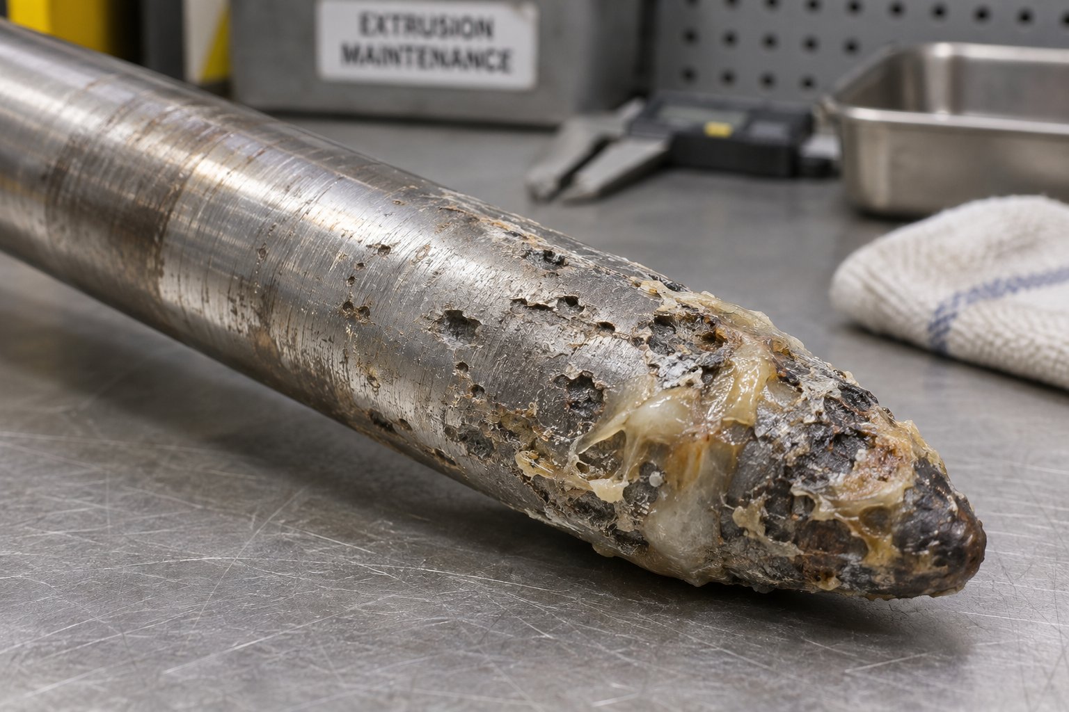
Troubleshooting Erratic Readings and Common Melt Thermocouple Failures
Your wiring is clean, your extension cables are the correct alloy, and cold-junction compensation checks out. Yet the temperature display still behaves strangely — sluggish to respond, jumping between values, or occasionally flashing an error code. The problem has shifted from the signal path to the sensor itself. Understanding how plastic melt-type thermocouples fail — and recognizing the early warning signs — separates a quick probe swap from hours of misguided troubleshooting aimed at the wrong component.
Melt thermocouple failures generally fall into three categories, each with distinct symptoms and root causes. Think of them as the slow, the erratic, and the dying.
Slow Response and Lagging Readings
You change a barrel setpoint or increase screw speed, and the melt temperature reading barely moves — or it creeps upward over minutes when it should respond in seconds. Sluggish response is one of the most common complaints, and it usually points to one of three causes.
First, consider the thermocouple construction itself. A heavy-walled sheath designed for extreme pressure ratings adds thermal mass between the melt and the sensing junction. That extra metal takes time to equilibrate. If your process demands fast response — injection molding shot-to-shot monitoring, for instance — and your probe was specified for a high-pressure extrusion application, the sheath may simply be too thick for the job.
Second, junction style matters. An ungrounded junction, where the sensing wires are insulated from the sheath tip by a layer of compacted MgO powder, inherently responds more slowly than a grounded junction because heat must conduct through that insulation before reaching the thermocouple wires. If your original installation used a grounded sensor and someone replaced it with an ungrounded version during maintenance, the response time difference can be noticeable — and confusing if the swap wasn't documented.
Third — and often overlooked — degraded polymer can cake onto the probe tip over time. This baked-on layer acts like thermal insulation, shielding the sensing junction from the flowing melt. The reading becomes increasingly representative of stagnant, partially carbonized material rather than the live process stream. Retractable melt thermocouples offer a practical advantage here: you can withdraw the probe during operation, inspect the tip, clean off any deposits, and re-insert without shutting down the line.
How do you confirm the diagnosis? The simplest method is a side-by-side comparison. Install a known-good sensor of identical type and construction in a nearby port and compare how quickly each responds to a deliberate process change. If the suspect probe lags significantly behind the reference, you've confirmed the problem is at the sensor — not in the controller or wiring.
Erratic Readings, Signal Noise, and Open-Circuit Failures
When a temperature display jumps wildly — bouncing 10 or 20 degrees within seconds — your first instinct might be to blame the thermocouple. Sometimes that instinct is right, but the root cause frequently lives outside the sensor itself.
Loose terminal connections are the number-one culprit. A thermocouple terminal screw that has backed out even a quarter-turn creates intermittent contact resistance that fluctuates with vibration and thermal expansion. The displayed temperature dances around unpredictably, and the problem may vanish temporarily when someone bumps the panel — only to return minutes later. As a field troubleshooting guide from Hongtai emphasizes, checking and re-tightening terminal screws should be your very first diagnostic step, before replacing anything.
Degraded extension wire insulation is the next suspect. Over months or years, heat radiating from the barrel, chemical vapors in the processing environment, and mechanical abrasion can crack or fray the insulation covering thermocouple extension leads. Damaged insulation allows the two conductors to intermittently short together or contact grounded metalwork, injecting spurious voltages into the signal. Pelican Wire's analysis of thermocouple wire failures identifies insulation breakdown as one of the seven primary root causes, noting that symptoms include erratic readings, electrical noise, and intermittent signal loss.
Moisture ingress into the thermocouple sheath itself creates a subtler but equally damaging problem. If the sheath seal at the tip or at the connection head is compromised — through a hairline crack, a poorly seated gasket, or corrosion-induced pinhole — humidity can penetrate the MgO insulation. Wet MgO conducts electricity, partially short-circuiting the thermocouple wires. The result is readings that drift unpredictably, especially during startup when the probe heats up and moisture migrates within the sheath.
Electromagnetic interference from variable-frequency drives, large motor starters, and barrel-band heater contactors can also produce jumping readings, but if you've followed the shielding and separation practices from the previous section, EMI is less likely to be the primary cause. When it is, the noise signature tends to be a fast, high-frequency oscillation superimposed on a stable baseline — distinctly different from the slow, random wandering caused by loose connections or wet insulation.
The most dramatic failure mode is the open circuit. When a thermocouple wire breaks — due to thermal fatigue, corrosion, or mechanical stress — the circuit is interrupted entirely. No millivolt signal reaches the controller. Most modern controllers respond by driving the display to maximum scale (often showing 9999 or a similar overflow value) or by displaying a dedicated fault code. An open-circuit condition is at least obvious. The real danger comes from intermittent opens, where a cracked wire makes and breaks contact with vibration or thermal expansion, producing sporadic spikes to full scale interspersed with apparently normal readings. These intermittent faults can masquerade as process disturbances for days before becoming permanent.
Sheath Degradation and When to Replace
Every melt thermocouple operates in a chemically active environment. The polymer melt isn't just hot — it can be corrosive, abrasive, or both. And while the thermocouple construction used for melt applications is engineered to resist these attacks, no sheath material is immune indefinitely.
Corrosive degradation is most aggressive with halogenated polymers. PVC processing releases hydrochloric acid at elevated temperatures. Fluoropolymers like PTFE and FEP can generate traces of hydrofluoric acid. Flame-retardant compounds — particularly those based on brominated or chlorinated chemistries — produce similarly aggressive byproducts. These acids attack the grain boundaries of stainless steel sheaths, causing pitting that progresses inward over time. Inconel sheaths resist this attack longer but are not exempt from it. A quick reference to any thermocouple melting points list will confirm that the metal itself won't melt at polymer processing temperatures, but chemical attack doesn't need to reach the melting threshold to destroy a sheath. Pitting and intergranular corrosion compromise structural integrity and create pathways for moisture and contaminants to reach the thermocouple wires inside.
Abrasive fillers cause a different kind of damage. Glass fiber — present at 10% to 50% loading in many engineering resins — acts like fine sandpaper against the probe tip. Mineral fillers such as calcium carbonate, talc, and wollastonite have a similar effect at high loading levels. Over thousands of hours, the sheath thins at the point of greatest exposure, eventually reaching a wall thickness where it can no longer withstand process pressure safely. Protective coatings such as ceramic, Stellite, or tungsten carbide can extend sheath life in severe erosion environments, but they add cost and are typically reserved for the most demanding applications.
How do you know when a melt thermocouple has reached end of life? Waiting for a catastrophic failure — a sheath breach, a full open circuit, or a melt leak through the fitting — is the most expensive option. A proactive approach uses the following replacement-trigger checklist:
- Visible sheath pitting or thinning — Any surface damage visible to the naked eye during a retraction inspection or scheduled removal signals that the protective barrier is compromised.
- Readings that drift outside calibration tolerance — If a comparison check against a reference sensor shows a deviation exceeding your process tolerance (often ±2 to ±3 °C for quality-critical applications), the thermocouple wire has likely undergone metallurgical changes.
- Intermittent open-circuit faults — Sporadic spikes to full-scale display indicate a wire that is cracking under thermal cycling or corrosive attack and will soon fail completely.
- Response time exceeding acceptable limits — A side-by-side test against a new sensor reveals whether polymer buildup, insulation degradation, or sheath thickening has slowed the probe beyond usefulness.
- Any evidence of melt leakage around the fitting — Polymer weeping past the seal washer or compression fitting means the pressure boundary is breached. The probe and possibly the sealing components must be replaced immediately.
Replacing a sensor when one or more of these triggers is present — rather than waiting for a production-stopping failure — protects both product quality and equipment integrity. The cost of a new probe is trivial compared to a rejected batch or an emergency shutdown to extract a seized, corroded melt bolt from a barrel port.
Recognizing failure symptoms, however, only tells you that something has gone wrong. It doesn't tell you whether the readings were drifting for weeks before the symptoms became obvious — or how far they had wandered from the truth. That invisible, gradual loss of accuracy is the most insidious threat to any thermocouple-based measurement, and it can only be caught through deliberate, periodic verification against a known reference.
Calibration, Drift, and Comparing Measurement Alternatives
A thermocouple that reads 235 °C today might read 238 °C six months from now — on the exact same melt stream, at the exact same process conditions. Nothing broke. No wire cracked. No terminal loosened. The sensor just... shifted. This slow, silent drift is the most dangerous failure mode a melt thermocouple can exhibit, because it never triggers an alarm, never throws a fault code, and never shows up as erratic behavior on the display. It simply moves your process window without telling you.
Calibration is the only defense against this invisible threat. Yet across competing guides and technical resources on polymer melt measurement, calibration receives almost no attention. That gap leaves processors flying blind — trusting a number that may have quietly wandered degrees away from reality.
Why Melt Thermocouples Drift Over Time
Drift originates inside the thermocouple wire itself. The Seebeck voltage your controller reads depends on the precise metallurgical composition and crystalline structure of the two alloy wires forming the sensing junction. When those wires sit at elevated temperatures for hours, days, and weeks on end, their internal structure changes — and so does the voltage they produce at a given temperature.
Several mechanisms drive this degradation:
- Grain growth and crystalline restructuring — Prolonged heat exposure causes the metal grains within the thermocouple wire to enlarge and realign. These metallurgical changes alter the thermoelectric properties of each conductor, shifting the voltage-temperature relationship that your controller's linearization algorithm assumes is fixed.
- Oxidation — Even inside a mineral-insulated sheath, trace amounts of oxygen can reach the wire surfaces over time. Oxidation preferentially attacks one conductor more than the other, introducing an asymmetric change in thermoelectric output. As research on environmental effects on thermocouples notes, surface-level contamination and oxidation amplify the impact of temperature-induced material changes.
- Contamination from process materials — Polymer decomposition byproducts that migrate through micro-defects in the sheath or past compromised seals can deposit on the wire surface, altering its composition at the molecular level. Halogenated resins like PVC and fluoropolymers are particularly aggressive contributors.
- Atomic ordering (Type K specific) — In the chromel leg of Type K thermocouples, prolonged exposure to temperatures in the 343 °C to 593 °C range causes short-range ordering of the crystal lattice. This phenomenon produces a cumulative positive drift that can reach several degrees over months of continuous operation — a well-documented characteristic that Type N thermocouples were specifically engineered to resist.
Two critical details make drift especially treacherous. First, it is cumulative: the longer the exposure, the greater the shift. A probe that has been in service for six months has drifted more than one installed last week, even if both are the same model and type. Second, drift accelerates with higher operating temperatures. A processor running PEEK at 380 °C will see thermocouple drift develop faster than one running polyethylene at 200 °C. One study cited in Electronics Cooling's thermocouple drift analysis found that sheathed Type N thermocouples exhibited drift as large as -10 to -13 °C after exposure to approximately 400 °C over test durations ranging from 300 to 1,200 hours — and that different sheathing materials on Type K sensors produced drifts of approximately -20 °C and +5 °C after 1,000 hours at 1,200 °C. While those extreme temperatures exceed polymer processing ranges, the underlying mechanism operates at lower temperatures too, just more slowly.
The practical takeaway? A thermocouple that melts its way through months of continuous service without a single fault or alarm may nonetheless be feeding your controller a number that is 3, 5, or even 8 degrees away from reality. And in quality-sensitive processes — medical tubing, automotive fuel-system components, optical-grade film — that invisible offset can mean the difference between in-spec production and an entire shift of scrap.
Calibration Methods and Recommended Frequency
Calibration doesn't mean adjusting the thermocouple — you can't tune a passive wire. It means comparing the probe's output against a traceable reference standard and documenting the deviation. If the deviation exceeds your acceptable tolerance, you replace the sensor. If it falls within tolerance, you record the result, note the date, and return the probe to service with confidence that the number on your screen still means what you think it means.
Two practical approaches dominate plant-floor thermocouple verification:
Dry-block calibrator comparison. A dry-block (or dry-well) calibrator heats a precision-machined metal block to a series of known temperatures. You insert the melt thermocouple alongside a reference-standard sensor — typically a calibrated RTD or a reference-grade thermocouple with a current certification — and compare readings at each setpoint. As Kaye Instruments' calibration selection guide explains, dry blocks are compact, portable, and well-suited to straight, small-diameter probes like thermocouples, making them the most convenient option for on-site verification. The key requirement is proper insert selection: the calibration well must closely match the probe diameter to ensure adequate thermal contact and minimize air-gap error.
Controlled-temperature bath comparison. A stirred liquid bath — using silicone oil, water, or other media depending on the target range — provides superior thermal uniformity and contact compared to a dry block. This makes baths the preferred choice when you need the lowest possible uncertainty or when calibrating probes with irregular geometries. The tradeoff is that baths are bulkier, require fluid management, and are less practical for field use. For polymer processing facilities with an in-house metrology lab, a bath-based comparison at two or three points spanning the operating range gives the most reliable drift assessment.
Ice-point verification. The simplest field check of all uses a properly prepared ice-water bath at 0 °C. Submerge the thermocouple tip in a mixture of crushed ice and distilled water, wait for the reading to stabilize, and note the deviation from 0.0 °C. This won't characterize drift across your full operating range, but it does provide a quick, zero-cost sanity check that catches gross errors — a broken wire, a corroded junction, or a controller misconfiguration — in minutes. Many experienced technicians perform an ice-point check whenever they remove and reinstall a probe, simply as a confidence verification before committing it back to the process.
A thermocouple that has drifted just a few degrees can push a process outside its validated window, causing scrap, dimensional variation, or degraded material properties — long before the deviation becomes visually obvious.
How often should you calibrate? The answer depends on the stakes involved. Processors in quality-critical industries — medical device manufacturers, automotive Tier 1 suppliers, pharmaceutical and food packaging operations — typically verify melt thermocouples on a fixed schedule: every 3 to 6 months, or after a set number of production hours, whichever comes first. Some regulated environments require calibration records as part of their quality management system, with results traceable to national measurement standards.
General-purpose operations often take a less formal approach, verifying only when readings seem suspect or when a probe is removed for maintenance. That strategy works until it doesn't — and when it fails, the root cause is almost always a gradual drift that accumulated unnoticed between checks. A good compromise is to pair scheduled calibration with event-triggered verification: check any probe that has been in continuous service for more than 2,000 hours, any probe that has been exposed to a particularly aggressive resin run, and any probe that shows even subtle changes in reading consistency.
Melt Thermocouples vs Infrared and RTD Alternatives
Thermocouples aren't the only technology capable of measuring temperature in polymer processing. Two alternatives occasionally surface in discussions — infrared pyrometers and resistance temperature detectors (RTDs) — and understanding their strengths and limitations helps clarify why immersion thermocouples remain the dominant choice for true melt measurement.
Infrared (IR) pyrometers measure temperature without physical contact. An optical sensor captures the thermal radiation emitted by the polymer surface and converts it to a temperature value. This sounds ideal — no probe to corrode, no sheath to erode, no immersion depth to debate. The catch? IR sensors read surface temperature only. They cannot see into the interior of the melt stream, which means they miss the radial gradients that make melt measurement necessary in the first place. Worse, their accuracy depends heavily on the emissivity of the target material. Polymer emissivity varies with resin type, color, filler content, and surface texture. A transparent or reflective melt — common with unfilled polycarbonate or certain grades of PET — can fool an IR sensor into reading far below the actual temperature. IR pyrometers have a legitimate role in measuring surface temperatures of extruded profiles, sheet, and film after they exit the die, but they are not a substitute for an immersion probe inside the melt channel.
Resistance temperature detectors (RTDs) use the predictable change in electrical resistance of a platinum element to measure temperature. Compared to thermocouples, they offer superior accuracy (typically ±0.1 °C to ±0.35 °C versus ±1.5 °C for standard thermocouple classes), better long-term stability, and near-zero drift — attributes that Tempsens' comparison of RTD versus thermocouple technology highlights as key differentiators. So why aren't RTDs the default in polymer processing? Response time is one reason: the platinum sensing element's physical mass makes RTDs slower to react to rapid temperature changes than a fine-wire thermocouple junction. More critically, RTDs are mechanically fragile compared to a swaged, mineral-insulated thermocouple cable. The vibration, high pressures, and mechanical shock inherent in barrel-mounted melt applications can damage delicate RTD elements that would survive indefinitely in a laboratory or pipeline installation. RTDs also max out at approximately 850 °C — adequate for plastics but limiting for facilities that also process metals or ceramics.
The table below captures how these three measurement technologies compare across the factors that matter most for polymer melt applications:
| Characteristic | Thermocouple (Melt Immersion) | Infrared Pyrometer | RTD (Pt100) |
|---|---|---|---|
| Measurement Type | Direct contact with flowing melt | Non-contact; surface radiation only | Direct contact; resistance-based |
| Response Speed | Fast (grounded junction) to moderate (ungrounded) | Very fast (milliseconds) | Moderate to slow |
| Accuracy (Typical) | ±1.5 °C (Class 1) to ±2.5 °C (Class 2) | ±1% to ±2% of reading; emissivity-dependent | ±0.1 °C to ±0.35 °C (Class A) |
| Long-Term Stability | Subject to drift; requires periodic calibration | Stable (no contact degradation); lens fouling possible | Excellent; minimal drift over years |
| Relative Cost | Low to moderate | Moderate to high | Moderate |
| Polymer-Processing Suitability | Excellent — purpose-built for high-pressure, corrosive melt environments | Limited to surface measurement after die exit; not suitable for in-barrel melt | Limited — fragile construction and slower response restrict use in high-pressure, high-vibration melt applications |
For the vast majority of in-barrel and in-die polymer melt measurement, thermocouples remain the practical choice. They tolerate the pressure, survive the chemistry, respond quickly enough for process control, and cost little enough to deploy at multiple points along the flow path. Their one significant weakness — drift — is manageable through the calibration practices described above.
Exotic thermocouple types like tungsten-rhenium, with a melting point above 2,000 °C, occasionally appear in searches from engineers working in melting furnace environments or ultra-high-temperature metallurgy. These have no role in plastics processing, where even the most demanding engineering resins top out below 450 °C. The standard Type J, K, and N options, paired with a disciplined calibration schedule, cover the entire polymer temperature spectrum with margin to spare.
Drift detection, calibration verification, and technology comparison all serve the same goal: making sure the number on your screen matches what's actually happening inside the melt channel. When a probe eventually falls outside acceptable tolerance — or reaches any of the replacement triggers identified in the troubleshooting section — the next step is finding a replacement that matches your specifications exactly. And that sourcing process, from gathering the right dimensional data to evaluating potential suppliers, has its own set of pitfalls worth navigating carefully.
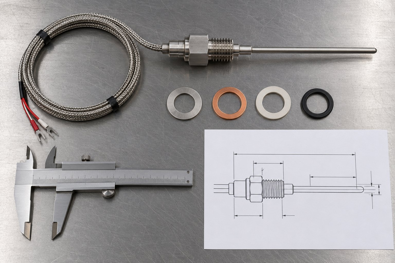
Sourcing Replacement Melt Thermocouples and Spare Parts
A melt thermocouple that fails a calibration check or trips one of the replacement triggers discussed earlier needs to come out of the barrel — and a correctly specified replacement needs to go in. That sounds simple enough, but ordering the wrong probe is one of the most common and costly mistakes maintenance teams make. Two sensors can look nearly identical on the outside — same thread, same lead wire color, same general shape — and still differ in immersion depth, junction style, sheath alloy, or thermocouple type in ways that shift your displayed temperature by several degrees the moment you power up. Getting the replacement right on the first order saves days of troubleshooting and eliminates the risk of running production on a sensor that doesn't match your validated process parameters.
What to Evaluate When Sourcing Replacement Probes
Imagine pulling a worn melt thermocouple from a barrel port and handing someone the task of ordering a replacement. If the only information that person communicates to the supplier is "I need a Type K melt bolt thermocouple," you're headed straight into what one thermocouple manufacturer's ordering guide calls "email ping-pong" — a multi-day exchange of clarifying questions that delays the order and increases the chance of miscommunication. An industrial thermocouple is not a commodity fastener. It is a highly customizable instrument where a single mismatched specification can render it useless — or worse, functional but inaccurate.
The critical specifications you need to pin down before contacting any supplier include:
- Thermocouple type (calibration) — Type J, K, or N. This must match your controller's input configuration exactly. A Type J probe plugged into a Type K input channel will display a temperature, but the number will be wrong by a margin that grows with temperature. If you're unsure what you have, check the wire colors against a thermocouple color code chart: Type K uses yellow and red (ANSI standard), while Type J uses white and red.
- Bolt thread size and length — Common formats include 1/2"-20 UNF, M18x1.5, and the widely used 5/16 melt bolt thermocouple configuration found on many extrusion adapters and die assemblies. Thread pitch, engagement length, and hex size must all match the existing barrel port. A thread gauge eliminates guesswork.
- Sheath diameter — The outer diameter of the sensing probe that extends into the melt channel. Even a fraction of a millimeter difference can affect how the probe seats in the bore and the thermal contact it makes with the flowing polymer.
- Immersion depth — The distance from the barrel wall face to the sensing tip. As earlier sections made clear, a change of just a few millimeters shifts the reading from the boundary layer into the flowing melt core — or vice versa. Measure the old probe carefully, from the sealing face of the bolt to the tip.
- Connection type — Lead wire termination (bare leads, plug connector, or terminal head), wire insulation material (fiberglass for high ambient temperatures, PFA for chemical resistance), and cable length. A probe with a 1-meter lead wire won't reach a panel that's 3 meters away, and splicing copper extension wire into the gap introduces the measurement errors discussed in the signal conditioning section.
- Pressure rating — Especially critical in injection molding, where instantaneous pressures during the injection phase can far exceed the steady-state values common in extrusion. A probe rated for 5,000 psi may be perfectly adequate on an extruder adapter but dangerously undersized in a molding nozzle that sees 20,000 psi spikes.
- Machine OEM part numbers — If the original sensor carries a manufacturer's part number, reference it. Many OEM numbers cross-reference to standard thermocouple configurations that suppliers can replicate exactly.
The single most effective thing a maintenance team can do to ensure a correct replacement order is to send the supplier a dimensional drawing of the old probe — or, better yet, the worn probe itself along with clear photographs and caliper measurements. Every reputable thermocouple supplier will tell you the same thing: a sketch with dimensions beats a verbal description every time. When a variable depth melt thermocouple or a retractable design is involved, the internal sliding mechanism, seal components, and housing dimensions add layers of complexity that plain-text descriptions rarely capture adequately.
Sourcing Thermocouples and Related Spare Parts
Where you source replacement probes depends on your priorities — speed, cost, technical support, and whether you need just the thermocouple or a broader set of barrel-zone components at the same time. Several sourcing strategies serve different operational realities.
OEM direct replacement is the lowest-risk option. Ordering the identical part number from the machine manufacturer guarantees dimensional and electrical compatibility. The downside? OEM pricing typically carries a premium, and lead times can stretch to weeks, especially for older machines or discontinued sensor models. For critical production lines where a validated sensor specification cannot change, OEM sourcing is often the right call despite the cost.
Specialty thermocouple manufacturers — companies that build custom probes to customer specifications — offer a balance of precision and flexibility. They can replicate an OEM design from your drawing or worn sample, often at lower cost and shorter lead time. The key is providing complete specifications (the checklist above) so the manufacturer's engineering team can verify compatibility before production begins.
Consolidated spare-parts suppliers appeal to maintenance teams and equipment rebuilders who prefer to minimize the number of vendors they manage. Instead of placing separate orders for thermocouples, nozzle tips, check rings, and barrel accessories from different sources, a single supplier handles the entire barrel-zone component set. This approach reduces procurement overhead and simplifies inventory management — particularly for facilities running multiple machine brands.
One example of this consolidated approach is NANHAIYA's extrusion and injection molding spare parts catalog, which covers screw tips, check rings, non-return valves, injection nozzles, and thermocouples alongside other barrel-zone components. For maintenance teams already sourcing mechanical wear parts like screw tips or non-return valves, adding thermocouples to the same order streamlines procurement. An important detail to note: their currently listed thermocouple is described for barrel-temperature measurement rather than confirmed melt-probe specification. Teams requiring immersion-style or melt bolt designs should submit drawings, worn samples, and dimensional details so NANHAIYA can assess compatibility and manufacturing feasibility before quoting. That kind of upfront communication — the same best practice that applies to any thermocouple supplier — prevents the specification mismatches that lead to wrong-part shipments and wasted downtime.
Related components such as nozzle tips, barrel liners, and check rings often reach end of life on a similar schedule to the thermocouples installed nearby. Bundling these items into a single procurement cycle reduces shipping costs and ensures that every component in the barrel zone starts fresh at the same time, giving you a clean baseline for process validation.
Regardless of which sourcing path you choose, a few universal principles apply:
- Never order from memory alone. Pull the old probe, measure it, photograph it, and reference any visible part numbers before placing the order.
- Confirm the thermocouple type matches your controller input. A Type K probe on a Type J channel — or vice versa — produces plausible but incorrect readings that can run undetected for weeks.
- Verify the type K thermocouple melting point and wire rating exceed your maximum process temperature with margin. The type K thermocouple wire melting point sits above 1,400 °C, so wire survival is never the concern in plastics — but sustained operation near the upper limit of a given type accelerates drift, making thermocouple selection a longevity decision as much as a compatibility one.
- Request a calibration certificate if your quality system requires traceable measurement. Many suppliers offer NIST-traceable calibration as an add-on service at the time of manufacture, which is far more convenient than calibrating in-house after delivery.
- Stock at least one spare per critical measurement point. A melt thermocouple failure at 2 AM on a continuous extrusion line is not the time to discover that your preferred supplier needs five business days to ship a replacement.
The entire lifecycle of a melt thermocouple — from selecting the right type and construction, through installing it at the correct depth with proper torque and wiring, to calibrating it on schedule and sourcing an accurate replacement when it reaches end of life — forms a single, interconnected measurement system. Skip any link in that chain, and the number on your controller screen stops meaning what you think it means. Get every link right, and you have something no barrel-zone sensor can provide: a direct, trustworthy window into the thermal state of the polymer that becomes your product.
Frequently Asked Questions About Melt Thermocouples
1. What is the difference between a melt thermocouple and a barrel thermocouple?
A barrel thermocouple sits flush against or embedded within the barrel wall, measuring the temperature of the surrounding steel. A melt thermocouple protrudes through the barrel wall so its sensing tip contacts the flowing polymer directly. Because molten plastics conduct heat 70 to 200 times less efficiently than steel, barrel readings can differ from actual melt temperature by 35 degrees Celsius or more. This gap makes melt thermocouples essential for any quality-sensitive polymer process where true material temperature drives part quality, fill behavior, and material integrity.
2. How deep should a melt thermocouple be inserted into the barrel?
A widely cited starting guideline is approximately 6 mm of immersion past the barrel wall, but the most reliable principle is to position the sensing tip at roughly one-third of the melt-channel diameter. At that depth, the junction clears the stagnant boundary layer influenced by barrel-wall temperature and samples representative flowing polymer. Going too shallow means you read barrel temperature rather than melt temperature. Going too deep risks flow obstruction, mechanical stress on the sheath, and localized shear heating at the sensor tip. Optimal depth also varies with screw design, throughput rate, and barrel diameter.
3. How often should melt thermocouples be calibrated?
Quality-critical industries such as medical device manufacturing, automotive, and food packaging typically calibrate melt thermocouples every 3 to 6 months or after a set number of production hours. General-purpose operations often verify only when readings seem suspect, though this risks undetected drift. A practical compromise is scheduled calibration paired with event-triggered checks: verify any probe in continuous service beyond 2,000 hours, after exposure to aggressive resins like PVC or fluoropolymers, or whenever reading consistency changes. Dry-block calibrators and ice-point checks are the most common plant-floor verification methods.
4. What causes erratic or jumping melt thermocouple readings?
The most common cause is loose terminal connections at the controller or junction box, where even a quarter-turn of looseness creates intermittent contact resistance. Other frequent culprits include degraded extension wire insulation that allows conductors to short or contact grounded metalwork, moisture ingress through a compromised sheath seal that partially shorts the internal wires, and electromagnetic interference from VFDs or heater contactors coupling into unshielded signal cables. Before replacing the sensor, always re-tighten terminals, inspect wire insulation, verify shielding, and confirm that thermocouple extension cables are physically separated from power wiring.
5. Can I use an RTD or infrared sensor instead of a melt thermocouple?
Each technology has trade-offs. Infrared pyrometers measure surface temperature only and cannot read inside the melt stream, making them unsuitable for in-barrel measurement. Their accuracy also depends on polymer emissivity, which varies by resin type and color. RTDs offer superior accuracy and near-zero drift but are mechanically fragile compared to mineral-insulated thermocouple cables, making them vulnerable to the high pressures and vibration inside plasticating barrels. For in-barrel and in-die polymer melt measurement, thermocouples remain the most practical choice due to their pressure tolerance, chemical resistance, fast response, and low cost per measurement point.
Written by
Nanhaiya Technical Team
Zhoushan Nanhaiya Plastic Machinery Co., Ltd.
The Nanhaiya technical team supports screw and barrel manufacturing projects through application review, technical communication, custom manufacturing coordination, and production and quality control.
Discuss Your Application
Related Articles
More insights on screw barrel technology and plastics processing.
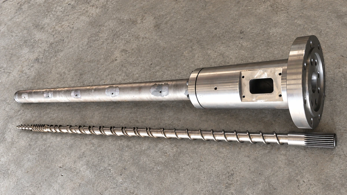
Why Your Single Screw Extruder Design Causes Extrusion Defects
Nov 13, 2026
Learn how single screw extruder design parameters—L/D ratio, compression ratio, channel depth, and mixing elements—affect melt quality, throughput, and defects.
Read Article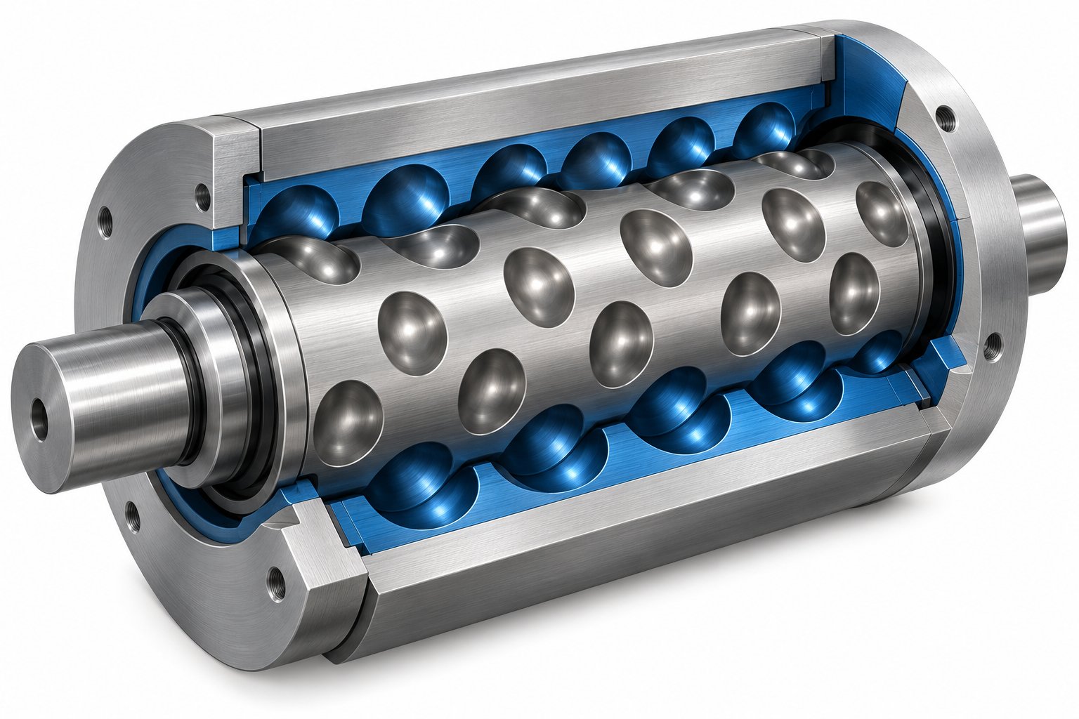
Cavity Transfer Mixer: The Blender Your Extruder Didn't Know It Needed
Nov 13, 2026
Learn how a cavity transfer mixer (CTM) upgrades single-screw extruder mixing. Covers working principles, key parameters, integration, applications, and comparisons.
Read Article
Extruder Barrel Alignment Decoded: Tolerances Most Plants Miss
Nov 13, 2026
Learn extruder barrel alignment tolerances, laser procedures, thermal offsets, and proactive schedules most plants miss — for single-screw and twin-screw lines.
Read ArticleLooking for something else?
Search by material, symptom or product and jump straight to the relevant page.
These are navigation suggestions based on keyword matching — not a quotation, not a delivery commitment, and not a substitute for engineering review. Final specification is confirmed by our engineers against your drawings and processed material.
Need help with screw barrel selection?
Share your machine model, processed material and application. Our team can help with pricing and technical support.