

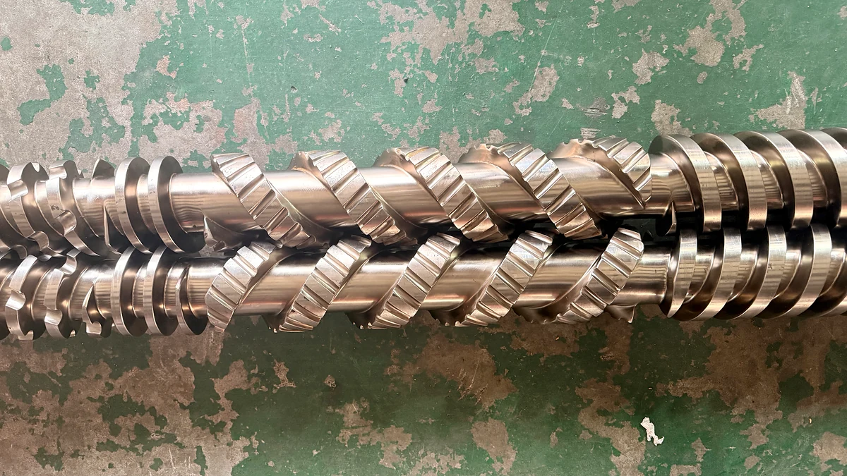
What Is a Plasticating Screw and Why It Matters
Imagine dumping a bucket of hard plastic pellets into a machine and expecting a perfectly shaped, defect-free part on the other end. Something has to bridge that gap between raw resin and homogeneous melt - and that something is a single rotating component buried inside the barrel of every injection molding machine and extruder.
A plasticating screw is a helical-flighted shaft housed inside a heated barrel that conveys, compresses, melts, and meters solid polymer into a uniform molten state ready for shaping.
That definition is the one you'll want to bookmark. Every shot you mold and every meter of extrudate you produce depends on how well this component performs those four jobs in sequence.
Defining the Plasticating Screw
If you arrived here searching for thread forming screws for plastic, self tapping screws for plastic, or plastic screw inserts - those are fastener-type hardware items used to join plastic parts together. A plasticating screw is an entirely different component. It lives inside the plasticating unit of a polymer processing machine, and its sole purpose is to transform solid pellets or powder into a consistent, pressurized melt. The screw rotates within a close-fitting barrel, and through a combination of mechanical shear and conducted heat, it does the heavy thermodynamic work that no other part of the machine can replicate. As industry sources emphasize, plasticization and melt uniformity directly determine a final product's strength, elasticity, surface smoothness, and dimensional accuracy.
Injection Molding vs. Extrusion Context
The plasticating screw appears in two major contexts. In extrusion, it rotates continuously, pushing a steady stream of melt through a die to form profiles, films, sheets, or pipes. In injection molding, the screw rotates to plasticize a measured dose of polymer, then acts as a ram - driving forward axially to inject that dose into a mold cavity. Research published in Polymers highlights that while the underlying melting physics are similar in both processes, injection molding adds cyclic complexity: the screw must start, stop, retract, and inject, which changes residence time, pressure profiles, and melting behavior compared to continuous extrusion. This article covers screw design principles relevant to both contexts because the core geometry - flights, channels, compression zones - serves the same fundamental purpose regardless of machine type.
Who Needs to Understand Screw Design
You don't need to be a polymer scientist to benefit from understanding how this component works. Process engineers adjust screw speed, back pressure, and temperature profiles every day - decisions that interact directly with screw geometry. Tooling managers approve screw purchases and need to match the design to the resin and application. Maintenance teams measure wear, diagnose melt-quality defects, and decide when a screw has reached end of life. For all three groups, the screw is the variable that sits upstream of every quality problem and every efficiency gain in the plasticating process.
So what exactly are the individual features that make up this critical component, and how does each one influence what happens to the polymer traveling through the barrel? The answers start with understanding the screw's anatomy - its flights, channels, and the three distinct functional zones that divide it from end to end.
Anatomy and Terminology of the Plasticating Screw
Pick up any technical manual on injection molding or extrusion, and you'll quickly run into terms like "flight clearance," "root diameter," or "helix angle" - often without a clear explanation of what each one means or where it sits on the screw. That gap in clarity leads to miscommunication between process engineers and tooling suppliers, and it can turn a straightforward screw replacement into a frustrating guessing game. A shared vocabulary is the foundation for every design decision that follows.
Screw Flight and Channel Terminology
Think of a plasticating screw as a cylinder wrapped with a continuous spiral ridge. That ridge is the flight - the raised helical land that pushes polymer forward much like the thread on a bolt moves a nut. The open valley between consecutive flights is the channel, and this is where the resin actually sits, compresses, and eventually melts as it travels along the barrel.
Several dimensions define how these features interact with the polymer:
- Root diameter - the diameter measured at the bottom of the channel, across the screw's solid core. It determines channel depth and changes from zone to zone.
- Outside diameter (OD) - the diameter measured at the tips of the flights. On most single-screw designs, the OD stays constant along the entire length, with the radial clearance-to-diameter ratio typically around 0.001, ranging from 0.0005 to 0.0020.
- Pitch - the axial distance from one flight to the next corresponding flight. On a standard "square pitch" screw, the pitch equals the OD.
- Lead - the axial distance the flight advances in one full revolution. For a single-flighted screw, lead and pitch are identical; for multi-flighted designs, they differ.
- Helix angle - the angle the flight makes relative to a plane perpendicular to the screw axis. A standard square-pitch screw has a helix angle of approximately 17.66 degrees.
- Flight width (land width) - the thickness of the flight measured along the screw axis. Wider flights increase shear on the melt film but reduce the open channel area available for throughput.
- Flight clearance - the tiny radial gap between the flight tip and the barrel wall. This clearance must be tight enough to prevent excessive melt backflow yet large enough to avoid metal-to-metal contact and premature wear.
You'll notice that none of these features exist in isolation. Change the root diameter, and you change channel depth. Alter the pitch, and you shift the helix angle. Every dimension on the screw is linked, which is exactly why precise terminology matters when specifying a plastic screw for processing rather than a plastic screw used as a fastener.
The Three Functional Zones Explained
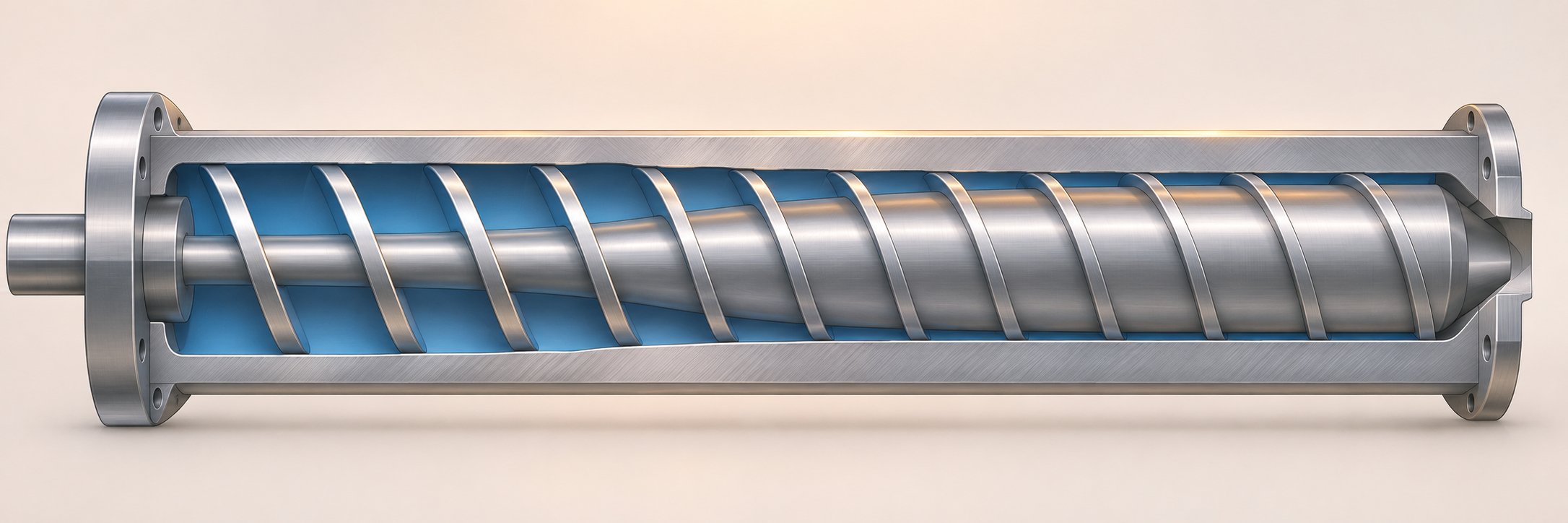
A standard single-flighted plasticating screw is divided into three zones, each responsible for a distinct phase of polymer processing. These zones are created not by separate mechanical parts but by the constant pitch yet varying channel depth along the screw's length.
Feed section. Here, the channel is deepest, and the root diameter is at its smallest. Solid pellets or powder drop from the hopper into these deep channels and are conveyed forward by the rotation of the flights against the barrel wall. Friction between the polymer and the barrel surface is the primary driving force - without it, the pellets would simply spin in place. The resin remains mostly solid throughout this zone, and efficient solids conveying depends on keeping the feed throat cool to maintain a high friction differential between the barrel wall and the screw surface.
Transition (compression) section. The root diameter gradually increases, which shrinks the channel depth and physically compresses the polymer. This compression squeezes out air trapped between pellets and forces the solid bed against the hot barrel wall, accelerating heat transfer. Melting begins in earnest here, driven by a combination of conducted barrel heat and viscous shear. The rate at which the channel depth decreases - the compression gradient - directly influences how aggressively the resin is melted and compacted.
Metering section. The channel is shallowest and the root diameter largest, both remaining constant across this zone. By this point, the polymer should be fully molten. The metering section's job is to generate a uniform, pressurized flow of melt at a consistent temperature, ready to pass through a die or into a mold cavity. Shallow channels in this zone create high shear rates that further homogenize temperature and mix any remaining inconsistencies in the melt.
Reference Table of Plasticating Screw Nomenclature
The table below consolidates every key term into a single scannable reference. Keep it handy next time you're reviewing a screw drawing or discussing specifications with a supplier - whether you're working with plastic screws in a processing context or evaluating screws with plastic washers used elsewhere, precise language prevents costly mistakes.
| Term | Definition | Typical Location on the Screw |
|---|---|---|
| Flight | Helical ridge that conveys polymer forward along the barrel | Entire screw length |
| Channel | Open space between consecutive flights where resin resides | Entire screw length |
| Root Diameter | Diameter at the base of the channel (screw core) | Varies - smallest in feed, largest in metering |
| Outside Diameter (OD) | Diameter at the flight tips; typically constant along the screw | Entire screw length |
| Pitch | Axial distance from one flight to the next corresponding flight | Entire screw length (usually constant) |
| Lead | Axial advance per full revolution; equals pitch on single-flighted screws | Entire screw length |
| Helix Angle | Angle between the flight and a plane perpendicular to the screw axis (~17.66° at square pitch) | Entire screw length |
| Flight Width | Axial thickness of the flight land | Entire screw length |
| Flight Clearance | Radial gap between the flight tip and the barrel bore | Entire screw length |
| Channel Depth | Radial distance from the root to the flight tip; (OD - root diameter) / 2 | Deepest in feed zone, shallowest in metering zone |
The second table maps each functional zone to its primary role, so you can see at a glance how the screw's geometry orchestrates the complete transformation from solid pellets to pressurized melt.
| Zone | Channel Depth | Primary Function | State of Polymer |
|---|---|---|---|
| Feed Section | Deep (constant) | Solids conveying - receives and transports pellets or powder forward via barrel-wall friction | Solid |
| Transition (Compression) Section | Progressively decreasing | Melting - compresses and plasticates the solid bed through shear and conducted heat | Solid + melt mixture |
| Metering Section | Shallow (constant) | Melt metering - homogenizes temperature and delivers melt at uniform pressure | Fully molten |
These terms and zones form the language you'll need for every topic ahead - from understanding how compression ratio and L/D ratio are calculated, to diagnosing why a particular screw geometry produces unmelts in one resin but works perfectly with another. The geometry of each zone doesn't just describe the screw; it dictates the quality of your melt.
Key Design Parameters That Control Melt Quality
Knowing the names of each feature on a plasticating screw is one thing. Understanding the numerical values behind those features - and how shifting one number ripples through every quality metric in your process - is where real melt control begins. This section puts concrete numbers and practical ranges on the parameters that matter most, so you can evaluate whether your current screw geometry actually fits the resin you're running.
L/D Ratio and Its Processing Impact
L/D ratio - the flighted length of the screw divided by its nominal diameter - is the simplest way to express how much working room a screw has for melting, mixing, and pressure generation. The most common L/D sits around 24:1, with some screws as short as 20:1 and others stretching to 30:1 or beyond.
What do those numbers mean in practice? A 20:1 screw on a 60 mm barrel is only 1,200 mm of flighted length. That's tight: you have fewer turns to distribute among the feed, transition, and metering zones, which limits how gently you can taper the compression and how thoroughly you can homogenize the melt. A 24:1 screw on the same barrel stretches to 1,440 mm - enough for a well-balanced three-zone layout on most commodity resins. Push to 30:1 (1,800 mm) and you gain extra turns for longer transition zones, additional mixing sections, or vented two-stage designs. The trade-off? Longer residence time means more heat history, which can degrade shear-sensitive polymers like PVC or certain bioplastics. Longer is not automatically better - it has to match the material's thermal tolerance and the process goal.
How Compression Ratio Is Calculated
Compression ratio quantifies how aggressively the screw squeezes polymer as it travels from the feed zone to the metering zone. The calculation itself is straightforward:
Compression Ratio = Feed-Zone Channel Depth (Hf) ÷ Metering-Zone Channel Depth (Hm). A screw with a 10 mm feed depth and a 2 mm metering depth has a compression ratio of 5.0:1.
That single number quietly governs melting efficiency, melt homogeneity, and output consistency. Too low a ratio for a given resin leaves pellets poorly compacted, trapping air that causes splay, gels, and pressure instability. Too high, and the screw overfeeds the downstream section, generating excessive shear heat, promoting degradation, and even plugging mixers.
Why does resin type matter so much here? Semi-crystalline polymers like HDPE and nylon undergo a large density change when they melt - their ordered crystalline structure collapses, and the bulk-to-melt density gap can be significant. Compression ratios of 3.0:1 to 4.5:1 are typical to fully consolidate that solid bed. Amorphous resins such as polystyrene and polycarbonate have no crystalline phase to collapse, so the density change during melting is modest. Ratios of 2.0:1 to 3.0:1 are usually sufficient - push higher and you generate unnecessary shear heat with no benefit to solids conveying. Heat-sensitive materials like PVC sit at the bottom of the range (1.5:1 to 2.5:1) because aggressive compression creates internal friction that barrel cooling alone cannot offset within PVC's narrow thermal window.
Trade-Offs in Screw Geometry Decisions
Here's where screw design gets interesting - and frustrating. Every parameter you adjust to improve one outcome tends to compromise another. Think of it as a three-way tug-of-war between throughput, melt homogeneity, and wear life:
- Deepen the channels to increase throughput, and you sacrifice mixing intensity because the melt sees lower shear rates in those deeper passages.
- Narrow the flight width below the standard 10% of barrel diameter to gain more open channel area, and you allow greater melt leakage back over the flights - reducing pumping efficiency and accelerating wear at the flight tips.
- Steepen the helix angle (increase pitch beyond square pitch) to move material faster per revolution, and you shorten effective residence time, which can leave the polymer undermixed or incompletely melted.
- Increase the compression ratio for better melting completeness, and you ramp up viscous dissipation - converting more motor energy into heat that can degrade sensitive resins and increase specific energy consumption.
This conflict-of-objectives reality means there is no single "best" screw geometry. Each parameter must be designed as part of a package - L/D, compression ratio, channel depth, pitch, and flight width all interacting simultaneously. The table below summarizes the key parameters, their practical ranges, and the melt-quality effects you can expect when adjusting each one.
| Parameter | Definition | Typical Range | Effect on Melt Quality |
|---|---|---|---|
| L/D Ratio | Flighted screw length divided by nominal diameter | 20:1 - 30:1 (24:1 most common) | Higher L/D increases melting and mixing capacity but raises residence time and degradation risk for heat-sensitive resins |
| Compression Ratio | Feed channel depth ÷ metering channel depth (Hf / Hm) | 1.5:1 - 4.5:1 (resin-dependent) | Controls melting intensity; too low causes unmelts, too high causes degradation and excessive shear heating |
| Channel Depth (Feed) | Radial distance from root to flight tip in the feed zone | Set by resin bulk density; deeper for low-density pellets or powder | Deeper channels increase solids intake but reduce shear and mixing effectiveness |
| Channel Depth (Metering) | Radial distance from root to flight tip in the metering zone | Typically 25-50% of feed depth | Shallower channels improve melt homogeneity and pumping stability; too shallow increases shear heating |
| Flight Width | Axial thickness of the flight land | ~10% of barrel diameter | Wider flights increase shear on the melt film in the clearance zone but reduce open channel area for throughput |
| Helix Angle | Angle between the flight and a plane perpendicular to the screw axis | ~17.66° (square pitch) | Steeper angles move material faster per revolution, reducing residence time; affects the balance between drag flow and pressure flow |
| Pitch | Axial distance from one flight to the next | Equal to diameter (square pitch) is standard; variable pitch used for special applications | Tighter pitch slows conveying rate and increases residence time; wider pitch boosts output but may reduce melting completeness |
Notice how nearly every "Typical Range" column includes a qualifier - resin-dependent, set by bulk density, application-specific. That's the core lesson. Screws for plastic processing cannot be specified by a single favorite number. The geometry has to reflect the physics of the specific polymer flowing through it: how it melts, how it flows, and how much mechanical energy it can absorb before it degrades. Those physics - drag flow, pressure flow, and the melting mechanism itself - are exactly what separate a well-designed plasticating screw from one that merely looks right on a spec sheet.
How a Plasticating Screw Melts Polymer
Numbers on a spec sheet tell you what the screw looks like. But they don't tell you what actually happens to each pellet as it spirals from hopper to nozzle. That story is written in physics - drag forces, pressure gradients, viscous dissipation, and a melting mechanism that plays out one thin film at a time inside the channel. Understanding these forces is the difference between reading a screw drawing and truly controlling what it does to your polymer.
Drag Flow and Pressure Flow in the Metering Zone
Picture the screw as stationary and the barrel rotating around it - an inversion that polymer scientists use because it simplifies the math without changing the physics. In this reference frame, the barrel wall drags the melt forward along the channel like a conveyor belt pulling a viscous fluid. This is drag flow, and it's the primary mechanism that moves polymer from the feed end toward the discharge. Its magnitude depends on barrel circumferential speed, channel depth, and the melt's viscosity.
Working against drag flow is pressure flow. As the screw builds pressure to push melt through a die or past a non-return valve, a pressure gradient develops along the channel. That gradient drives melt backward - from the high-pressure discharge end toward the lower-pressure feed end - through the same channel the drag flow is trying to fill. The net output of the metering zone is the difference between these two competing flows.
Why does this matter on the shop floor? When you increase back pressure on an injection molding machine, you steepen the pressure gradient, which amplifies the backward pressure flow component. Net throughput drops, but the melt spends more time in the channel under higher shear, improving homogeneity and mixing. Reduce back pressure, and the drag component dominates: throughput rises, but the melt may arrive at the screw tip with temperature gradients and poorly dispersed additives. Every back-pressure adjustment you make is essentially a rebalance of this drag-versus-pressure equation.
Research into leakage-flow effects in metering channels has shown that the flight clearance introduces a third flow component. Melt escaping over the flight tips from the high-pressure side to the low-pressure side reduces pumping efficiency, especially as clearance grows with wear. For shear-thinning polymer melts - which covers virtually every commercial resin - this leakage becomes increasingly pressure-sensitive, meaning small changes in processing conditions can produce disproportionate shifts in output stability.
The Melting Mechanism Along the Screw Channel
Drag and pressure flows explain how melt moves, but how does solid resin become melt in the first place? The answer was first described systematically by Tadmor in 1966, and decades of refinement have validated the core concept while adding nuance. Here's the mechanism in plain terms.
As solid pellets are conveyed into the transition zone, they compact into a dense plug called the solid bed. This bed presses against the hot barrel wall, and a thin film of melt forms at the interface - initially just micrometers thick. The barrel's relative rotation drags this thin melt film in the cross-channel direction, sweeping it off the barrel surface and depositing it against the advancing (pushing) flight. There, the film accumulates into a melt pool that grows progressively wider as more barrel-contact melting feeds it.
Meanwhile, the solid bed itself shrinks - primarily in width, as the melt pool expands to occupy the channel. Experimental investigations using the classic Maddock screw-pull technique - where the extruder is stopped abruptly, cooled, and the solidified channel content is sectioned - have confirmed this pattern across both semi-crystalline and amorphous resins. Cross-sections taken along the screw clearly show a solid bed narrowing from one end to the other, with a melt pool widening on the pushing-flight side.
What drives the energy input? Not barrel heaters alone. The dominant contributor is viscous dissipation - mechanical energy converted to heat as the melt film shears between the moving barrel surface and the stationary solid bed beneath it. The thinner the film, the higher the shear rate, and the more intense the heat generation. This is why shear heating, not barrel conduction, accounts for the majority of the melting energy in most extrusion and injection molding processes. Barrel heaters set the thermal boundary conditions and initiate the first melt film, but the screw's rotation does the heavy thermodynamic lifting.
One complication worth noting: the solid bed doesn't always behave like a rigid plug. At higher screw speeds, solid bed break-up can occur in the compression and metering zones, fragmenting the plug into isolated chunks surrounded by melt. These fragments melt unevenly, producing temperature variations and unmelt that persist all the way to the screw tip. Research at Paderborn University observed break-ups becoming more frequent above 120 rpm on shorter compression zones and above 180 rpm on longer ones - a practical ceiling that explains why simply cranking up screw speed doesn't always solve throughput problems.
Connecting Physics to Process Settings
Every process knob you turn connects back to the physics described above. Consider the sequence that transforms a pellet into a pressurized, homogeneous melt:
- Pellet entry. Gravity feeds solid pellets from the hopper into the deep-channeled feed section. A cooled feed throat maintains a friction differential - high friction against the barrel wall, low friction against the screw root - to ensure forward conveying rather than co-rotation with the screw.
- Solids compaction. As the channel depth begins to decrease in the transition zone, air is expelled and pellets compress into a dense solid bed that spans the full channel width.
- Melt-film formation. The compacted bed contacts the heated barrel wall. Conducted heat softens the outermost layer, creating a thin melt film at the barrel-polymer interface. This initial film thickness is influenced by barrel temperature, the polymer's flow temperature, and even the porosity of the pellet bed surface, which reduces heat transfer at the start of melting.
- Melt-pool growth. Barrel rotation drags the melt film cross-channel into the melt pool on the pushing-flight side. Viscous shear within the film generates the majority of the melting energy. The solid bed narrows progressively as more material joins the melt pool.
- Solid bed elimination. Through the combined action of conducted heat and viscous dissipation, the solid bed is consumed entirely - ideally before the polymer exits the transition zone.
- Melt homogenization and metering. In the shallow metering section, the fully molten polymer experiences high shear that evens out temperature gradients. Drag flow pushes the melt forward against the pressure gradient, delivering a uniform, pressurized stream to the screw tip, die, or non-return valve.
When this sequence plays out cleanly, you get stable shot weights, consistent melt temperature, and defect-free parts. When it doesn't, the physics point directly to the cause:
- Unmelts reaching the mold or die - the solid bed wasn't fully consumed before the metering zone. Root causes include a screw for plastic processing with too low a compression ratio for the resin, insufficient L/D for the melting rate required, or screw speed set too high for the barrel temperature profile.
- Material degradation (black specks, discoloration) - excessive viscous dissipation in shallow channels or extended residence time in stagnant zones. Overly aggressive compression ratios, excessive back pressure, or worn flights that create dead spots can all push sensitive polymers past their thermal limits.
- Inconsistent melt temperature - solid bed break-up sending fragments of varying size into the metering zone. Each fragment melts at a different rate, producing a temperature distribution rather than a single melt temperature. Reducing screw speed, adjusting barrel profile, or switching to a screw geometry with a longer, gentler compression gradient can stabilize the solid bed and narrow the temperature spread.
The takeaway is direct: barrel heaters and process settings interact with screw geometry, but the geometry itself dictates where and how melting energy is delivered. A well-matched screw for your specific plastic and process makes every knob adjustment more predictable. A mismatched one forces constant compensation - tweaking temperatures, speeds, and pressures to work around a mechanical reality that tuning alone cannot fix.
That raises the obvious follow-up question. If a single screw geometry can't serve every resin and application equally well, what types of plasticating screws exist, and how do you pick the right one?
Types of Plasticating Screws Compared
The answer, it turns out, is not a single universal screw but an entire family of designs - each built around a different strategy for melting, mixing, and conveying polymer. Most processors start with whatever screw shipped inside the machine. Whether that default is the right tool for the job is a question surprisingly few shops ever ask. Understanding what's available - and where each design excels or falls short - is the first step toward making that call.
General-Purpose Screws and Their Limitations
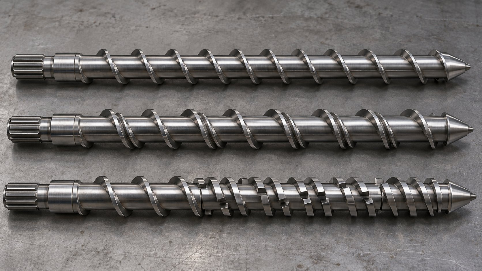
The general-purpose (GP) screw is by far the most widely installed plasticating screw in the industry. Its design is the classic three-zone layout covered in earlier sections: a deep-channeled feed section, a tapered transition section, and a shallow metering section, all on a single flight. It's simple to manufacture, relatively inexpensive, and capable of processing a broad range of resins at moderate speeds. For many shops running mixed-material schedules, a GP screw is the pragmatic default.
But "good enough for everything" often means "ideal for nothing." The GP screw's fundamental weakness lies in its single-channel melting mechanism. As the solid bed shrinks and the melt pool grows, nothing physically separates the two. At higher screw speeds, the solid bed breaks apart - fragments of unmelted pellet get swept into the melt pool and carried downstream before they finish melting. Independent testing at the University of Massachusetts confirmed this effect: the GP design showed the highest throughput potential but suffered from excessive melt-temperature variation and pressure surging above 40 RPM.
The result on the shop floor? Unmelts in molded parts, gels in extruded film, inconsistent shot weights, and operators chasing temperature and back-pressure adjustments to compensate for a problem that's fundamentally geometric - not procedural. If you've been fighting these symptoms despite careful process tuning, the screw itself may be the root cause.
Barrier, Mixing, and Wave Screw Designs
Engineers developed alternative screw geometries specifically to address the GP screw's melting and mixing shortcomings. Here are the major types you'll encounter.
Barrier screws. The defining feature is a secondary flight - the barrier flight - introduced in the transition zone that splits the channel into two separate passages: a solids channel and a melt channel. Only fully molten polymer can cross over the barrier flight (which has a controlled undercut clearance), so unmelted chunks are physically retained until they finish melting. This eliminates solid-bed break-up and delivers a thermally homogeneous melt to the metering zone.
Two principal barrier configurations dominate. The Maillefer (crossing) type uses a barrier flight that gradually crosses from the pushing flight to the trailing flight, progressively narrowing the solids channel. The Barr (parallel) type runs the barrier flight roughly parallel to the main flight, creating a wider solids channel with approximately one-third more melting surface area on a screw of equivalent axial length. This makes parallel designs generally better suited for polymers with higher melting-energy requirements - materials with high melting points, high specific heats, or strong shear-thinning behavior. Crossing barrier screws, conversely, handle lower-energy polymers well and create less disruption to the solid bed at the barrier start, making them a better fit for hard or slippery resins whose solid beds are more fragile.
Modifications like the Dray-Lawrence type increase the lead (helix angle) within the barrier section to push more volume through the melting zone for higher output. As Jim Frankland of Frankland Plastics Consulting notes, increasing the lead by 25% on a 3.5-inch screw boosts melting area by less than 10% due to fewer total turns - the real benefit is greater volumetric capacity, not dramatically faster melting. Barrier screws commonly deliver 20% or more additional output compared to a GP screw of the same diameter and L/D, along with significantly tighter melt-temperature uniformity.
Dispersive and distributive mixing screws. Mixing is a separate challenge from melting, and many screw designs address it with dedicated mixing elements added to the metering zone or positioned between the barrier and metering sections. Dispersive mixers use high-shear features - tight clearances, barrier undercuts, or fluted sections - to break apart agglomerates such as pigment clusters, filler bundles, or gels. Distributive mixers use cavity-transfer geometry, pin elements, or notched flights to fold and redistribute the melt stream without adding excessive shear. The ideal mixing section often combines both principles. Reiloy USA has developed a screw that can be reconfigured between dispersive and distributive modes by adjusting barrier undercut height, notch geometry, number of flights, and root depth within the mixing section - allowing one screw to handle materials as rheologically different as ABS and nylon.
Wave screws. A wave screw replaces the conventional constant-depth metering section with a channel whose root oscillates in a sinusoidal pattern. The alternating peaks and valleys force the melt stream through repeated cycles of compression and expansion, enhancing mixing intensity and melt-temperature uniformity without adding separate mixer elements. Wave designs are particularly effective in blown film extrusion, where gauge uniformity is directly tied to melt homogeneity.
Energy-transfer (ET) screws. Developed by Robert Barr Inc., the ET screw and its successor, the Variable Barrier Energy Transfer (VBET) design, change leads and flight geometry in the melting section to reduce internal pressure, enabling better material flow while maintaining melt quality. By managing energy input more efficiently, these designs also reduce screw wear - a significant benefit in high-volume production. ET screws are available as dedicated designs or as retrofit options for conventional single-flighted GP screws.
Note: if your search brought you here looking for plastite screws for plastic assembly, plastic anchor screws, or screws with plastic anchors, those are fastener products used in joining applications - entirely different from the plasticating screw types discussed here. Similarly, a plastic screw anchor is a wall-mounting insert, not a polymer-processing component.
When to Move Beyond a GP Screw
The GP screw persists as the industry default because it works acceptably across many situations - especially at moderate speeds, with forgiving resins, and where part-quality tolerances are wide. The myth is that this acceptable range covers all production scenarios. It doesn't, and the cost of that assumption is hidden in scrap rates, longer cycles, and excess energy consumption that processors rarely attribute back to the screw.
Consider upgrading from a GP design when you encounter any of these situations:
- Output-limited by melting capacity. If pushing screw speed higher produces unmelts or pressure surging, a barrier screw attacks the root cause directly - it provides more melting area and prevents solid-bed break-up.
- Melt uniformity drives your quality spec. Film, sheet, optical parts, and tight-tolerance moldings all demand narrow melt-temperature distributions. A barrier screw with a mixing section can achieve melt-temperature uniformity within ±1 °C - a level a GP screw simply cannot sustain at production speeds.
- Color or additive dispersion is inconsistent. Adding a dispersive or distributive mixing section - whether as part of a new screw or retrofitted onto an existing one - addresses distribution problems that no amount of back-pressure adjustment can fully resolve.
- Energy costs are a concern. Barrier and ET screws melt polymer more efficiently per kilogram, meaning less motor energy wasted as excess heat that then has to be removed through cooling.
The table below provides a side-by-side comparison of the major plasticating screw types to help you match the right geometry to your processing challenge.
| Screw Type | Design Feature | Best-Fit Application | Limitations |
|---|---|---|---|
| General-Purpose (GP) | Single-flighted, three-zone layout with constant pitch; no barrier or mixing elements | Mixed-material shops running moderate speeds; wide part-quality tolerances; budget-constrained replacement | Solid-bed break-up at higher speeds; poor melt-temperature uniformity; limited mixing capability |
| Barrier - Maillefer (Crossing) | Secondary flight crosses from pushing to trailing flight, narrowing the solids channel progressively | Lower-energy polymers (low melting point, low specific heat); hard or slippery resins with fragile solid beds | Less melting surface area than parallel designs; may require metering section extension for high head-pressure applications |
| Barrier - Barr (Parallel) | Barrier flight runs roughly parallel to main flight, creating a wider solids channel with ~33% more melting area | Higher-energy semi-crystalline polymers (HDPE, PP, PA); output-limited processes; film and sheet extrusion | Can disrupt fragile solid beds at barrier start if not designed with gradual introduction; usually needs metering length after barrier section |
| Dispersive Mixing | High-shear elements (tight clearances, fluted sections, barrier undercuts) in the metering zone | Pigment dispersion; breaking filler agglomerates; eliminating gels in filled or masterbatch-colored resins | Adds shear heat; not suited for heat-sensitive polymers; can increase pressure drop |
| Distributive Mixing | Cavity-transfer geometry, pin elements, or notched flights that fold and redistribute melt without high shear | Blending additives, color concentrates, or multi-component melts; applications needing homogeneity without thermal degradation | Limited ability to break agglomerates; less effective alone when dispersive action is also needed |
| Wave | Oscillating (sinusoidal) root depth in the metering zone creates alternating compression and expansion | Blown film extrusion requiring tight gauge uniformity; applications where mixing must occur without separate mixer hardware | More complex to manufacture; geometry is application-sensitive and requires careful design |
| Energy Transfer (ET / VBET) | Modified leads and flight geometry in the melting section reduce internal pressure and improve material flow | High-volume extrusion where wear life and energy efficiency are priorities; retrofit upgrade for existing GP screws | Design-sensitive; poorly executed versions underperform; benefits depend on matching geometry to material properties |
Choosing the right screw type is only half the equation. A barrier screw optimized for HDPE won't perform the same way on polycarbonate, and a wave screw tuned for blown film may be entirely wrong for profile extrusion. The geometry that gives you the best melting and mixing also has to match the thermal behavior, viscosity profile, and mechanical sensitivity of the specific polymer family running through your barrel - a material-by-material consideration that shapes everything from compression ratio to screw metallurgy.
Material-Specific Screw Design Considerations
A barrier screw that excels on polyethylene can produce black specks in polycarbonate. A gentle-compression design perfect for PVC will leave nylon pellets half-melted. The reason is simple: every polymer family melts differently, flows differently, and punishes the wrong geometry in its own way. Matching screw design to resin behavior is arguably the single most impactful decision a processor can make - yet it's the one most often skipped in favor of a one-size-fits-all replacement.
Amorphous vs. Semi-Crystalline Screw Requirements
The distinction between these two polymer classes shapes every dimension on the plasticating screw, starting with how much energy each one demands. Injection molding expert John Bozzelli illustrates the gap vividly: nylon 6, a semi-crystalline resin, requires roughly 716 BTU/kg to melt, while ABS - an amorphous material processed at a similar temperature - needs only about 342 BTU/kg. That's nearly double the energy input for nylon, and the screw geometry has to deliver it.
Why the difference? Amorphous resins have randomly tangled polymer chains. As heat enters, they soften progressively - like frozen butter warming on a counter. A partially melted amorphous pellet is taffy-like, deformable, and relatively forgiving if it slips past the transition zone. Compression ratios of 2.0:1 to 3.0:1 and moderate transition lengths handle these materials well because the density change during melting is modest and the energy barrier is low.
Semi-crystalline resins behave more like ice. Their ordered chain structures stay rigid until the melting point is reached, then require an additional energy dose - the heat of fusion - to break apart the crystalline lattice. As Bozzelli puts it, they "do not soften until they reach their melting temperature." This creates a dramatic solid-to-melt transition that demands higher compression ratios (typically 3.0:1 to 4.5:1) and longer transition zones to ensure every pellet receives enough compaction and barrel-wall contact to fully melt. When the transition is too short, solid-bed break-up occurs - fragments of still-hard pellets escape into the metering zone, winding up in the part and wearing the screw along the way.
For processors running both polymer families on the same machine, this contrast is the root of many quality headaches. A screw designed for semi-crystalline PE will over-shear amorphous PS, while a screw optimized for ABS will under-compress nylon. If your operation handles a mixed resin schedule, two application-matched screws - swapped as needed - often outperform a single compromise geometry.
Handling Shear-Sensitive and High-Viscosity Polymers
Some resins don't just melt differently - they degrade differently, and screw geometry must respect those thermal boundaries.
Shear-sensitive materials like PVC and PMMA operate within narrow processing windows. PVC, in particular, releases hydrochloric acid when overheated, attacking both the polymer and the metal surfaces it contacts. Screws for these materials need shallow channels, gentle compression ratios (1.5:1 to 2.5:1), and ample L/D to spread the energy input over more screw turns. Aggressive compression or tight clearances generate localized hot spots that barrel cooling alone cannot correct.
On the opposite end, high-viscosity polymers such as HDPE and high-molecular-weight polyethylene (HMWPE) resist flow so strongly that shallow metering channels create excessive viscous dissipation. Deep-channel screw designs reduce shear rates in the metering zone, keeping melt temperature within acceptable limits. The trade-off is reduced mixing intensity - which is why high-viscosity screws often pair deep metering sections with dedicated mixing elements downstream to compensate.
Screw Metallurgy for Abrasive and Corrosive Resins
Geometry isn't the only variable that changes with the resin. Filled and reinforced polymers - glass-fiber-filled nylon, mineral-filled PP, carbon-fiber-reinforced PEEK - introduce hard particles that scour flight surfaces and widen clearances with alarming speed. Even unfilled semi-crystalline pellets cause measurable wear because they remain rigid until they reach melting temperature, grinding against the barrel and flights under compression.
Tooling managers need to understand three tiers of metallurgical protection:
- Nitrided steel. Gas nitriding hardens the surface of a standard 4140 steel screw to approximately 65-70 Rc. It's the baseline treatment - adequate for unfilled commodity resins but insufficient for glass-filled or mineral-loaded materials. Think of it as the entry-level defense.
- Hardfaced flights with tool-steel cores. Cobalt-based (Stellite) or nickel-chrome-boron (Colmonoy 56 or 83) weldments applied to the flight tips significantly extend wear life in abrasive service. Colmonoy 56 handles mildly corrosive and mildly abrasive resins, while Colmonoy 83 provides stronger protection at a higher cost. For barrels, tungsten-carbide-lined bimetallic sleeves resist abrasive scouring far longer than plain nitrided bores.
- Full corrosion-resistant alloys. Highly corrosive polymers such as fluoropolymers (producing hydrofluoric acid), PVC (hydrochloric acid), and acetals (formic acid) require nickel-based alloys - Hastelloy, Inconel, or Monel - for all melt-contact surfaces. DuPont recommends these alloys for all equipment processing its Teflon fluoropolymers, noting that even small cracks in chrome plating can undermine protection. HIP (hot isostatic pressing) barrels offer the best corrosion resistance available, though they cost three to four times more than standard bimetallic options.
One frequently overlooked detail: corrosion-resistant alloys have a lower coefficient of thermal expansion (CTE) than standard steel. When the barrel and screw expand at different rates during processing of high-temperature resins, the clearance changes - potentially causing the screw to bind and produce extreme flight wear. Matching the barrel and screw metallurgy for CTE compatibility is just as important as choosing the right hardness grade. This is the kind of detail that a screw manufacturer's technical team should evaluate during specification - not something to discover after installation when worn flights start generating black specks or when plastic screw hole plugs won't mask the cosmetic defects showing up in your finished parts.
The table below consolidates recommended compression ratios and screw design notes across the most common resin families. Use it as a starting reference when evaluating whether your current geometry fits the material running through it - and keep in mind that filled grades within any family shift the requirements toward more wear-resistant metallurgy and sometimes altered compression.
| Resin Family | Examples | Recommended Compression Ratio | Screw Design Notes |
|---|---|---|---|
| Amorphous - Standard | PS, ABS, SAN | 2.0:1 - 3.0:1 | Moderate transition length; lower energy requirement; GP or barrier screw both viable; good tolerance for processing variation |
| Amorphous - Engineering | PC, PPO, PSU | 2.0:1 - 2.8:1 | Higher melt temperatures; watch for shear sensitivity in thin channels; mixing section recommended for color consistency |
| Semi-Crystalline - Commodity | HDPE, PP, LLDPE | 3.0:1 - 4.0:1 | Long transition zone critical; barrier screw strongly preferred above 40% shot capacity; deep feed section for low-bulk-density pellets |
| Semi-Crystalline - Engineering | PA 6, PA 66, POM, PBT | 3.0:1 - 4.5:1 | High heat of fusion; L/D of 24:1 minimum; solid-bed break-up risk high with GP screws; POM is corrosive - requires nickel alloy contact surfaces |
| Shear-Sensitive | PVC (rigid and flexible), PMMA | 1.5:1 - 2.5:1 | Shallow channels; gentle compression gradient; avoid dead spots where material can stagnate and degrade; corrosion-resistant metallurgy required for PVC |
| High-Viscosity | HDPE (HMW), HMWPE, UHMWPE | 3.0:1 - 3.5:1 | Deep metering channels to limit viscous dissipation; mixing elements needed downstream; high torque demand on drive |
| Filled / Reinforced | GF-Nylon, GF-PP, mineral-filled resins | Match base resin family | Hardfaced flights (Stellite or Colmonoy); bimetallic barrel liner; increased flight clearance allowance to account for accelerated abrasive wear |
| Corrosive | Fluoropolymers (PTFE, FEP), flame-retardant compounds | Match base resin family | Full nickel-alloy construction (Hastelloy, Inconel); HIP barrels recommended; CTE-matched screw and barrel pairing essential |
Selecting the best screws for plastic processing always means matching two things simultaneously: the geometry to the resin's melting behavior and the metallurgy to the resin's chemical and mechanical aggression. Ignore either half of that equation, and you'll find yourself diagnosing the same defects repeatedly - unmelts, degradation, inconsistent dimensions - without ever tracing the problem back to a screw that simply wasn't designed for the material it's being asked to process. Those recurring defect patterns, and how to trace each one back to a specific screw-related root cause, are exactly where troubleshooting begins.
Common Plasticating Problems Traced to Screw Design
Recurring defects rarely announce their true origin. A process engineer sees unmelts in a part and reaches for the barrel temperature controller. A maintenance technician spots black specks and orders a purge compound. An operator notices shot-weight drift and bumps the cushion setting. Each response treats the symptom - but in a surprising number of cases, the root cause is the plasticating screw itself: its geometry, its condition, or the way it interacts with the non-return valve at the screw tip. Tracing defects back to their mechanical source - rather than endlessly tweaking process parameters - is the fastest path to a permanent fix.
Unmelts, Degradation, and Inconsistent Shot Weight
Three categories of plasticating failure account for the majority of screw-related quality complaints. Each one leaves a distinct signature on the finished part, and each one traces back to a specific geometric or wear-related issue inside the barrel.
Poor melt homogeneity (unmelts and gels). When solid fragments survive the transition zone and reach the metering section, they show up as hard spots, clear specks in opaque parts, or gels in film and sheet. The underlying mechanism is straightforward: the solid bed wasn't fully consumed before the polymer reached the shallow metering channel. Why? The compression ratio may be too low for the resin being processed - a GP screw designed for amorphous ABS, for example, will undercompress semi-crystalline nylon, leaving rigid pellet fragments intact. Alternatively, worn flights may have increased the radial clearance to the point where melt leaks backward over the flight tips instead of building the pressure needed to compact the solid bed. Industry analysis of screw wear confirms that as clearance increases, the screw loses pumping pressure - and without adequate pressure in the transition zone, melting stalls. A third possibility is excessive screw speed outrunning the melting rate, causing solid-bed break-up before the barrel can deliver enough thermal energy.
Material degradation (black specks and discoloration). If unmelts represent too little energy input, degradation represents too much - or too much time. Black specks are essentially carbonized polymer: resin that overheated in a dead zone, on a worn screw root, or inside a stagnant pocket where material couldn't refresh. When the screw has root wear - especially on the forwarding side of the flights - pockets form where material hangs up and degrades. Over time, thin flakes of carbon break loose and enter the melt stream, appearing as dark specks or streaks in the molded part. An overly aggressive compression ratio for a shear-sensitive resin creates a different degradation path: excessive viscous dissipation generates localized temperatures well above the barrel setpoint, and no amount of barrel cooling can offset heat generated inside the polymer mass itself. The result is the same - discolored, weakened resin reaching the mold cavity.
Inconsistent shot weight. Shot-to-shot weight variation in injection molding usually points to instability at the screw tip - specifically, at the non-return valve (check ring). But the screw's metering zone plays a direct supporting role. If the metering section delivers melt at an unsteady pressure - because of channel-depth inconsistencies from wear, or because the transition zone is sending partially melted slugs downstream - the check ring has to manage an unpredictable melt stream during every recovery stroke. Even a perfectly functioning check ring cannot fully compensate for a metering zone that delivers pulsating pressure rather than a smooth, steady flow.
Excessive screw recovery time. When the screw takes noticeably longer to plasticize a shot than it did when the machine was new, the culprit is almost always reduced conveying efficiency. Worn flights leak melt backward, so the screw has to rotate more turns to accumulate the same volume of material in front of the tip. Increased recovery time directly extends cycle time, eroding productivity - and if the operator compensates by raising screw speed, the additional shear can push melt temperature beyond spec, compounding quality issues.
Non-Return Valve Interaction and Wear
The non-return valve - most commonly a sliding check ring - is the mechanical handshake between the plasticating phase and the injection phase of every molding cycle. During screw recovery, the screw rotates and retracts. The check ring opens, allowing molten polymer to flow through channels in the screw tip and accumulate in front of it. When the screw drives forward to inject, the check ring slides backward and seats against its mating surface, sealing the melt in front of the screw so it can be pressurized into the mold.
When this seal is tight, the system works as designed: shot volume is repeatable, pack pressure transfers predictably, and cushion position remains stable. When the seal degrades - through wear of the check ring OD, the seat, or the tip body - melt slips past the valve during injection, and the screw creeps forward. The processor loses control over consistent packing of the cavities, creating dimensional variation, sink marks, and short shots that appear intermittent and random.
Here's the critical interaction: check-ring wear and screw wear compound each other. A worn metering zone delivers melt at inconsistent pressure, which forces the check ring to seal against varying flow conditions - accelerating its own wear. Meanwhile, a worn check ring that leaks during injection allows melt to flow backward into the metering channel, disrupting the next recovery stroke and introducing additional shear and residence time into material that has already been plasticized. The check-ring area is also a notorious location for material hang-up and degradation - restricted flow through the valve openings creates localized shear that can carbonize resin, especially during color changeovers when previous-run pigment gets trapped in dead spots.
Imagine you're troubleshooting a mold that produces acceptable parts for twenty shots, then suddenly throws a short shot followed by a part with black specks. The instinct is to check barrel temperatures or adjust transfer position. But the pattern - intermittent shorts combined with contamination - is a classic signature of a worn check ring releasing trapped, degraded material in bursts. If the screw flights upstream are also worn, the two problems feed each other in a cycle that process adjustments alone cannot break. Replacing the valve without inspecting the screw, or vice versa, often provides only temporary relief.
Diagnosing Screw Wear vs. Process Settings
The challenge for maintenance teams and process engineers is that screw wear mimics process-setting errors. A melt that's too hot could mean the barrel profile is set too high - or it could mean worn flights are generating excess shear. Inconsistent shot weight could be a transfer-position issue - or a leaking check ring. The symptoms overlap, which is why many shops chase process parameters for weeks before pulling the screw and discovering the real problem.
A systematic approach separates the two:
- Trend your recovery time. If the screw takes progressively longer to build the same shot at the same RPM and back pressure, conveying efficiency is declining - a mechanical issue, not a settings issue.
- Monitor cushion stability. Plot cushion position shot-to-shot. Increasing scatter indicates check-ring leakage or metering-zone instability - neither of which responds to transfer-position tuning.
- Check melt temperature at the nozzle. If actual melt temperature exceeds the barrel setpoint by more than 10-15 °F and continues to climb, excess shear from worn clearances is the likely driver. Worn screws force higher RPM to maintain output, which further elevates melt temperature in a self-reinforcing loop.
- Inspect purge shots. If black specks or discoloration persist after thorough purging, the contamination is mechanically lodged - in root-wear pockets, around the check ring, or in dead spots that purge compound cannot reach without a screw pull.
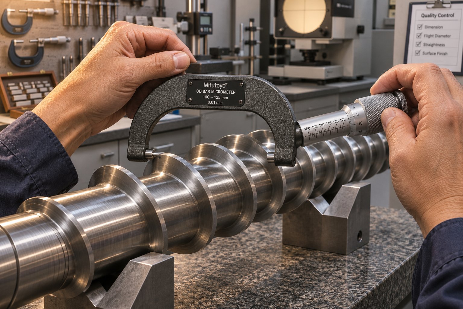
- Measure flight OD. A common rule of thumb flags replacement when radial clearance reaches four times the original tolerance, but as screw-wear research emphasizes, resin viscosity matters: a high-viscosity PE tolerates more clearance before output drops than a low-viscosity PP does under the same conditions.
Note: if you arrived here searching for plastic self tapping screws, self tapping screws plastic, plastic caps for screws, or plastic shutter screws, those are fastener and hardware products - not the plasticating screw components discussed in this troubleshooting guide.
The table below maps the most common plasticating problems to their symptoms, screw-related root causes, and corrective actions. Use it as a diagnostic starting point before investing time in process-parameter adjustments that may only mask a mechanical issue.
| Problem | Symptom | Likely Screw-Related Root Cause | Corrective Action |
|---|---|---|---|
| Unmelts / gels in parts | Hard spots, clear specks in opaque parts, surface roughness, fisheyes in film | Compression ratio too low for the resin; solid-bed break-up from excessive screw speed; worn flights reducing compaction pressure; GP screw lacking barrier geometry | Match compression ratio to resin family; reduce screw RPM; measure flight OD and replace if clearance exceeds limits; upgrade to barrier screw for semi-crystalline resins |
| Material degradation (black specks, discoloration) | Dark specks or streaks on part surface; yellowing or browning; burnt odor from nozzle | Root wear creating stagnant pockets; excessive compression ratio for shear-sensitive resin; material hang-up in check-ring area; dead spots from worn or pitted screw surfaces | Pull screw and inspect for root pitting and carbon buildup; reduce compression ratio or switch to shear-sensitive screw geometry; clean or replace check ring; verify barrel profile is not overheating rear zones |
| Inconsistent shot weight | Part weight variation shot to shot; intermittent short shots; unstable cushion position | Worn check ring allowing melt leakage during injection; metering zone delivering unsteady pressure due to channel wear; combined screw and check-ring wear compounding instability | Inspect and replace check ring, seat, and tip; measure metering-zone flight clearance; address both screw and valve wear together rather than individually |
| Excessive screw recovery time | Longer cycle times; screw takes more rotations to build same shot volume; motor load increases at same RPM | Worn flight OD increasing leakage flow; reduced solids-conveying efficiency from worn feed-section flights; loss of pumping pressure across metering zone | Measure flight OD wear along full screw length; evaluate rebuild vs. replacement based on wear severity; consider custom injection molding screw barrels matched to your machine specs, resin profile, and shot requirements for a tailored replacement |
| Melt-temperature variation | Parts with varying gloss, warpage, or shrinkage across production run; melt temp readings fluctuate more than ±5 °C | Solid-bed break-up sending uneven fragments into metering zone; insufficient mixing in GP screw; worn barrier flights losing separation effectiveness | Upgrade to barrier screw with mixing section; reduce screw speed to stabilize solid bed; if barrier flights are worn, have screw rebuilt or replaced with application-matched geometry |
| Pressure surging at die or nozzle | Cyclic fluctuations in head pressure; pulsating extrudate; dimensional variation in extruded profiles | Worn metering flights causing unstable pumping; solid-bed break-up in transition zone; improper L/D for the resin's melting requirements | Inspect and restore flight OD; lengthen transition zone or increase L/D on replacement screw; verify compression ratio matches the specific polymer being processed |
Every row in that table shares a common thread: the corrective action eventually leads back to evaluating the physical condition and geometric suitability of the screw. Process settings can mask a worn or mismatched screw for a while, but they cannot fix it. At some point, the screw needs to be pulled, measured, and either rebuilt or replaced - and the replacement needs to be specified for the application, not just grabbed off the shelf as a generic drop-in. That decision process - when to replace, how to measure wear, and what information to gather before ordering - is the final step in turning diagnosis into action.
Selecting and Replacing a Plasticating Screw
Diagnosing a screw-related problem is only half the battle. The other half is acting on that diagnosis - deciding whether to refurbish the existing screw or replace it entirely, measuring the actual wear to justify the decision, and then specifying a replacement that matches the application rather than simply replicating whatever came out of the barrel. This final step is where many shops stumble. They pull a worn screw, call the first supplier they find, order a generic replacement to the same nominal dimensions, and reinstall it without questioning whether the original geometry was right in the first place. That's how the same defects return six months later.
When to Replace or Refurbish a Plasticating Screw
Not every worn screw needs to go in the recycling bin. Refurbishment - welding hardfacing material back onto worn flights, regrinding to original OD, and re-nitriding - can restore a screw to serviceable condition at roughly 40-60% of the cost of a new one. But refurbishment has limits. It makes sense when the wear is confined to the flight tips and the root diameter remains within spec. It does not make sense when you see root pitting, cracks at the flight-to-root fillet, corrosion along the channel floor, or bowing that feeler gauges confirm exceeds a few thousandths. At that point, the screw's structural integrity is compromised, and rebuilding the flights on a weakened core buys time rather than reliability.
Santa Fe Machine Works identifies five practical triggers for replacement rather than repair: excessive surface damage such as cracking, pitting, or erosion; diminished efficiency showing up as longer cycle times or frequent downtime; maintenance costs that exceed the replacement price; design obsolescence that can't accommodate new materials or tighter tolerances; and loss of precision due to cumulative wear over thousands of operating hours. When two or more of these triggers overlap, replacement almost always delivers a better return than another rebuild cycle. Think of plastic screw covers on decorative hardware - they hide what's underneath for a while, but they don't fix the damage. The same logic applies to patching a screw that's past its useful life.
Measuring Screw and Barrel Wear
You can't make a replace-or-refurbish decision without numbers. Subjective inspection - eyeballing the flight edges or running a fingernail across the root - catches catastrophic damage but misses the gradual clearance increases that silently erode melt quality and output consistency. A structured measurement protocol turns guesswork into data.
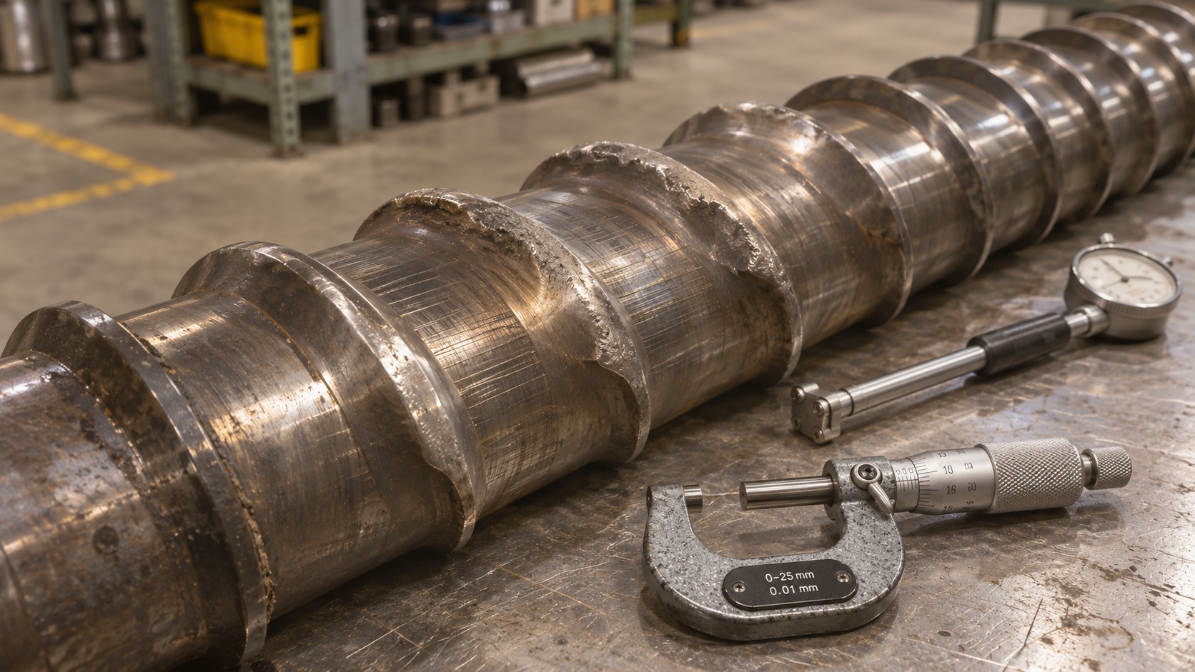
Screw measurement. Davis-Standard's maintenance guidelines lay out a clear sequence: remove the screw, clean all solidified resin using brass tools and copper gauze (never steel wire brushes, which damage the surface), and let the screw cool to room temperature before taking any readings. Establish a reference point at one end, number each flight, and lay a tape measure along the full length to correlate each measurement to a specific location on the screw. Using an OD bar micrometer - a standard micrometer modified with a parallel bar that spans across two flights - measure the outer diameter at every flight and log the values in a spreadsheet.
Plotting flight number versus measured OD against the original dimensions creates a visual wear profile. You'll immediately see which zones have worn fastest. The transition zone typically shows the most aggressive flight-tip wear because it's where partially melted, still-abrasive pellets are under maximum compression against the barrel wall. The feed section may wear faster if you're running glass-filled or mineral-loaded resins that are fully abrasive in their solid state.
Barrel measurement. Adams Engineers recommends using a bore gauge inserted from each end of the barrel, measuring as far down as you can reach from both sides. Record values and compare them to the original bore diameter. Over time, the barrel ID increases as material erodes the inner surface - especially in the transition and early metering zones where compaction forces and abrasive contact are highest.
Interpreting the numbers. The effective clearance is the gap between the measured barrel bore and the measured screw flight OD. Compare this to the original radial clearance (typically around 0.001 times the nominal diameter). Industry diametrical-wear guidelines categorize wear into three levels: low wear, where you may notice a slight decrease in output at a given RPM; medium wear, where the screw should be monitored closely with rebuild or replacement planned for the near future; and high wear, where the screw should be rebuilt or replaced immediately. The specific thresholds vary by screw diameter and resin viscosity, which is why trending your measurements over regular intervals - rather than relying on a single snapshot - gives the most actionable picture of component life remaining.
A good maintenance program schedules these inspections at regular intervals and logs every data point. Over several cycles, the wear profile reveals your component's expected lifespan in your specific production environment, enabling planned replacement rather than emergency downtime.
Specifying a Custom Replacement Screw for Your Application
Here's where most processors leave value on the table. The default instinct is to order a drop-in replacement - same dimensions, same geometry, same material grade as the original. That approach makes sense only if the original screw was already well-matched to your resin, your part, and your process requirements. As this entire article has shown, many factory-supplied screws are general-purpose compromises. Replacing a worn GP screw with a new GP screw perpetuates the same limitations.
A better approach treats screw replacement as a specification project. Walk through this evaluation process before contacting any supplier:
- Document the current screw's performance baseline. Record melt temperature (actual, not setpoint), recovery time, cushion stability, shot-weight variation, and any recurring defect patterns. This baseline tells you what the replacement needs to improve on - not just what dimensions to replicate.
- Identify the primary resin(s) and their processing demands. Use the compression-ratio and material-design tables from earlier sections to determine whether the existing geometry actually matches the polymer being processed. If you're running semi-crystalline nylon on a screw designed for amorphous ABS, the geometry mismatch is the first thing to correct.
- Evaluate whether a screw-type upgrade is justified. If you've been fighting unmelts, melt-temperature variation, or output limits on a GP screw, a barrier screw with a mixing section may deliver permanent relief that a like-for-like replacement never will.
- Assess barrel condition simultaneously. Replacing a worn screw into a worn barrel restores only half the clearance. Bore-gauge the barrel before ordering the screw so you can decide if the barrel needs relining or replacement at the same time - matching the pair is always more effective than addressing one component in isolation.
- Select metallurgy based on the resin's abrasive and corrosive characteristics. Filled resins demand hardfaced flights and bimetallic barrels. Corrosive resins need nickel-alloy construction. Specifying the wrong metal grade guarantees premature wear regardless of how perfect the geometry is.
- Gather all machine-specific data the supplier will need. A custom screw cannot be designed without precise information about your equipment and process targets.
When you're ready to contact a manufacturer, have the following data points organized and ready to share:
- Machine make, model, and clamp tonnage
- Barrel bore diameter (measured, not nominal, if the barrel has wear)
- Current screw dimensions: overall length, flighted length, L/D ratio, flight OD, root diameters in each zone
- Shot-size requirements (minimum and maximum)
- Primary resin(s) processed, including filler type and loading percentage
- Part-quality priorities (surface finish, dimensional tolerance, optical clarity, strength)
- Cycle-time targets and current recovery time
- Known defect history linked to plasticating performance
- Barrel metallurgy and condition (so the screw can be matched)
Manufacturers who specialize in application-matched components will use this information to engineer a screw that addresses your specific combination of machine, resin, and quality requirements. NANHAIYA, for example, builds custom injection molding screw barrels around the processor's machine specifications, resin characteristics, and shot requirements. Their technical review evaluates screw geometry, wear patterns, melting performance, mixing adequacy, and material-retention concerns - essentially mirroring the evaluation checklist above - to match the screw and barrel to the application rather than defaulting to a generic catalog geometry. That kind of application-level engineering is what separates a replacement that solves problems from one that simply restarts the same wear cycle.
One final point worth emphasizing: don't treat plastic screw covers or cosmetic fixes downstream as acceptable alternatives to addressing the root cause at the plasticating unit. Every quality defect, every cycle-time penalty, and every energy inefficiency traced to a worn or mismatched screw is a cost that compounds with every shot. The screw is where your melt problems start - and a properly specified replacement is where they end.
Frequently Asked Questions About Plasticating Screw Design
1. What is the difference between a plasticating screw and a regular plastic screw?
A plasticating screw is a helical-flighted shaft inside an injection molding machine or extruder barrel that conveys, compresses, melts, and meters solid polymer into a uniform molten state. It is an industrial processing component - not a fastener. Regular plastic screws, such as thread-forming or self-tapping screws for plastic, are hardware items used to mechanically join plastic parts together. The two share a name but serve entirely unrelated functions in manufacturing.
2. How does compression ratio affect plasticating screw performance?
Compression ratio is calculated by dividing the feed-zone channel depth by the metering-zone channel depth. It determines how aggressively the screw compacts and melts the polymer. Semi-crystalline resins like nylon and HDPE typically need ratios of 3.0:1 to 4.5:1 because their crystalline structure demands more energy to melt. Amorphous resins such as ABS and polycarbonate perform well at 2.0:1 to 3.0:1. Setting the ratio too low causes unmelts and trapped air, while setting it too high generates excessive shear heat that can degrade heat-sensitive materials like PVC.
3. When should I replace a plasticating screw instead of refurbishing it?
Refurbishment is cost-effective when wear is limited to the flight tips and the root diameter remains within specification. Replacement becomes the better option when you observe root pitting, cracks at the flight-to-root fillet, corrosion along the channel floor, or measurable bowing. Additional triggers include maintenance costs exceeding the replacement price, design obsolescence preventing use of new materials, and loss of precision from cumulative wear. Manufacturers like NANHAIYA offer custom injection molding screw barrels engineered around specific machine specs, resin profiles, and shot requirements, ensuring the replacement addresses the application rather than simply duplicating the original geometry.
4. What causes black specks in injection molded parts related to the screw?
Black specks are carbonized polymer - resin that overheated in stagnant zones, worn root surfaces, or dead spots inside the barrel. Root wear on the screw creates pockets where material hangs up, degrades over time, and eventually breaks loose into the melt stream. An overly aggressive compression ratio for shear-sensitive resins also generates localized temperatures far above barrel setpoints, carbonizing material internally. The non-return valve area is another common site for material hang-up and degradation, especially during color changeovers when pigment gets trapped in restricted flow paths.
5. What is the best L/D ratio for a plasticating screw?
There is no single best L/D ratio - it depends on the resin and process. The most common ratio is 24:1, which provides a well-balanced three-zone layout for most commodity resins. Shorter screws at 20:1 offer less working length for melting and mixing, making them suitable only for easy-to-process materials or smaller machines. Longer screws at 30:1 provide extra turns for extended transition zones, additional mixing sections, or vented two-stage designs, but they increase residence time, which can degrade heat-sensitive polymers. The right L/D must balance the polymer's melting energy requirement against its thermal sensitivity.
Written by
Nanhaiya Technical Team
Zhoushan Nanhaiya Plastic Machinery Co., Ltd.
The Nanhaiya technical team supports screw and barrel manufacturing projects through application review, technical communication, custom manufacturing coordination, and production and quality control.
Discuss Your Application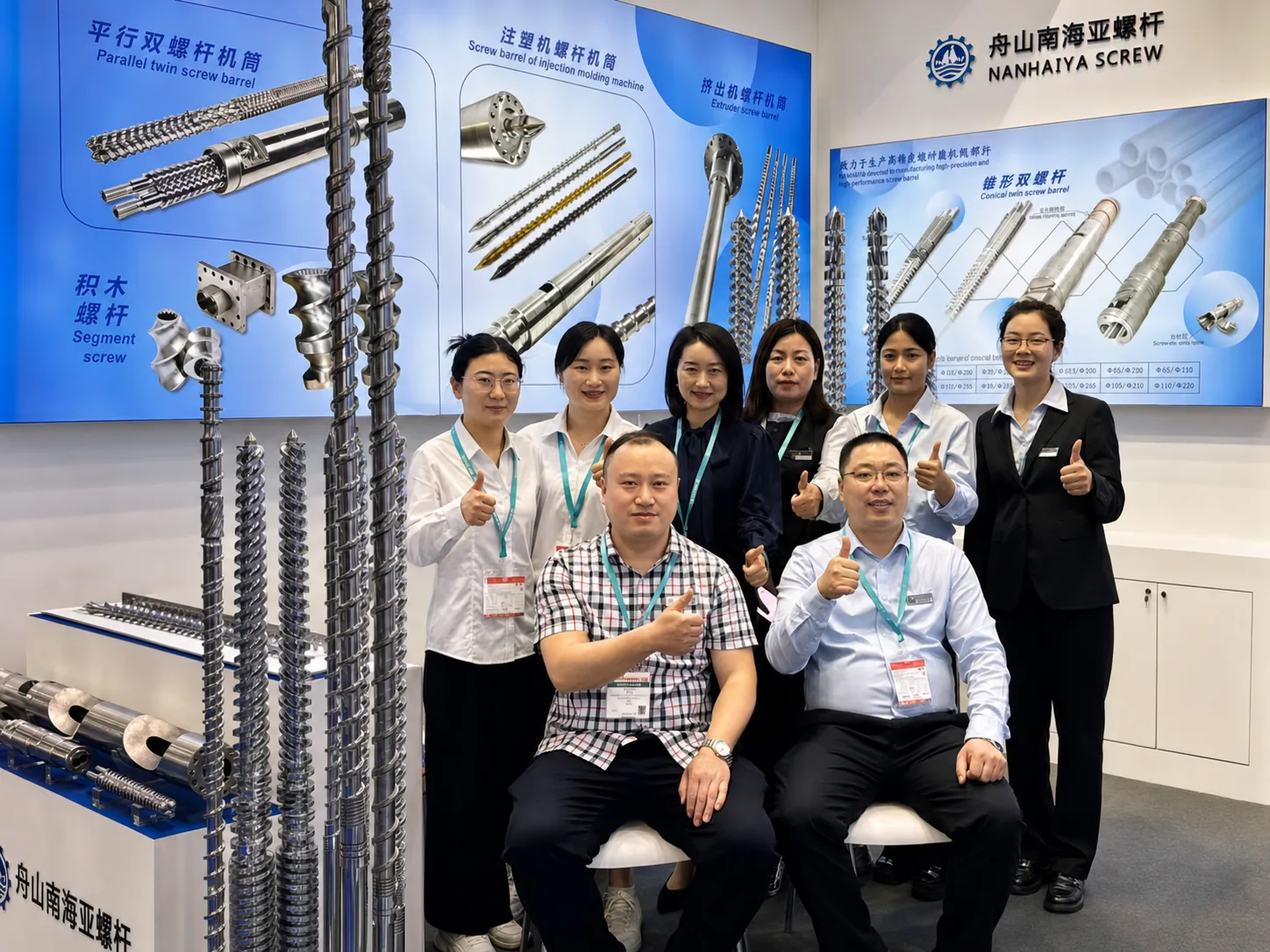
Related Articles
More insights on screw barrel technology and plastics processing.
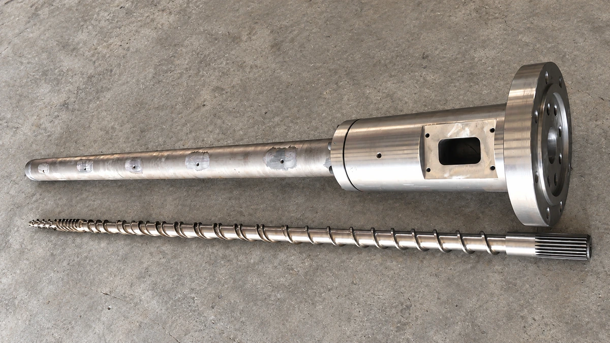
Why Your Single Screw Extruder Design Causes Extrusion Defects
Nov 13, 2026
Learn how single screw extruder design parameters—L/D ratio, compression ratio, channel depth, and mixing elements—affect melt quality, throughput, and defects.
Read Article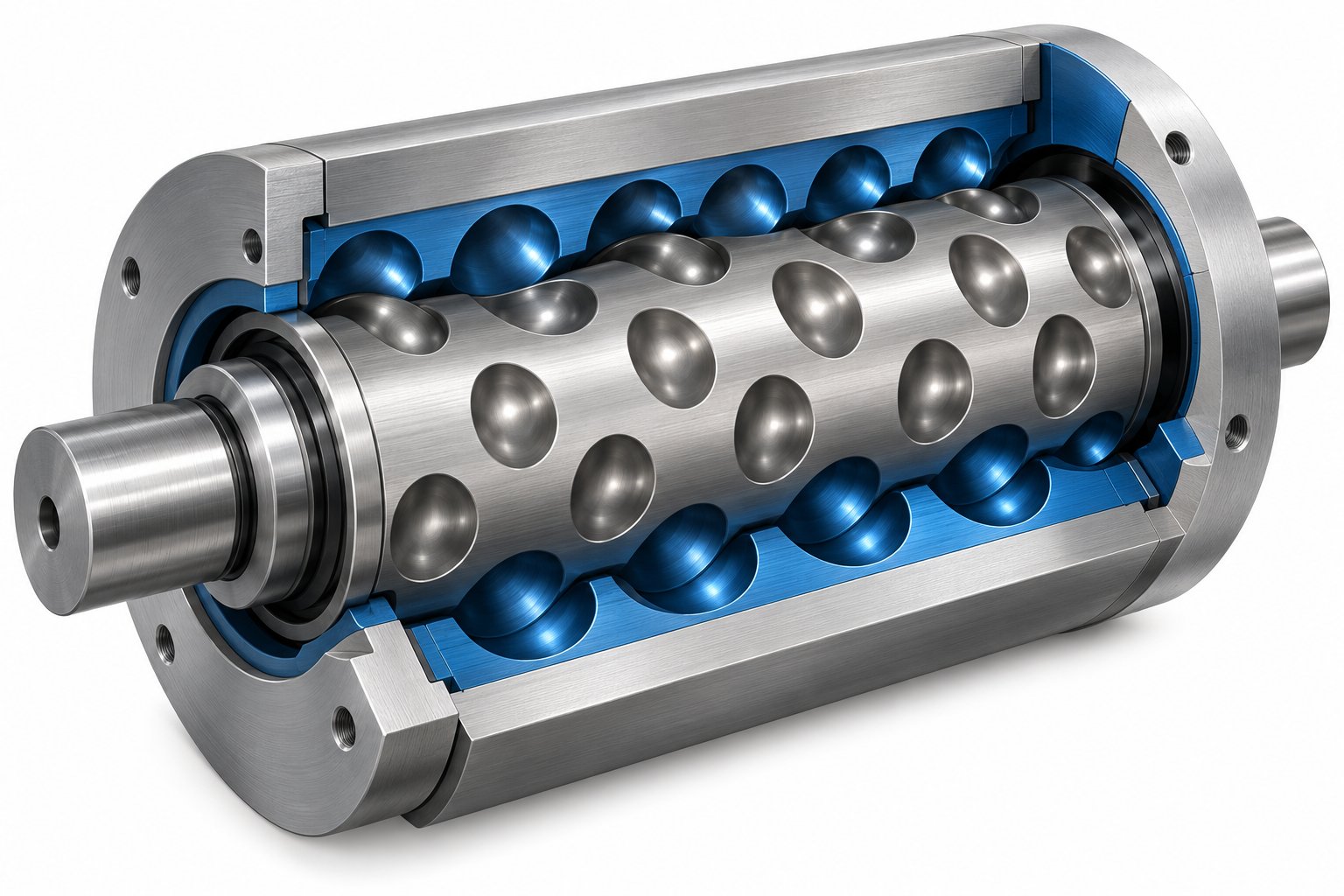
Cavity Transfer Mixer: The Blender Your Extruder Didn't Know It Needed
Nov 13, 2026
Learn how a cavity transfer mixer (CTM) upgrades single-screw extruder mixing. Covers working principles, key parameters, integration, applications, and comparisons.
Read Article
Extruder Barrel Alignment Decoded: Tolerances Most Plants Miss
Nov 13, 2026
Learn extruder barrel alignment tolerances, laser procedures, thermal offsets, and proactive schedules most plants miss — for single-screw and twin-screw lines.
Read ArticleLooking for something else?
Search by material, symptom or product and jump straight to the relevant page.
These are navigation suggestions based on keyword matching — not a quotation, not a delivery commitment, and not a substitute for engineering review. Final specification is confirmed by our engineers against your drawings and processed material.
Need help with screw barrel selection?
Share your machine model, processed material and application. Our team can help with pricing and technical support.