

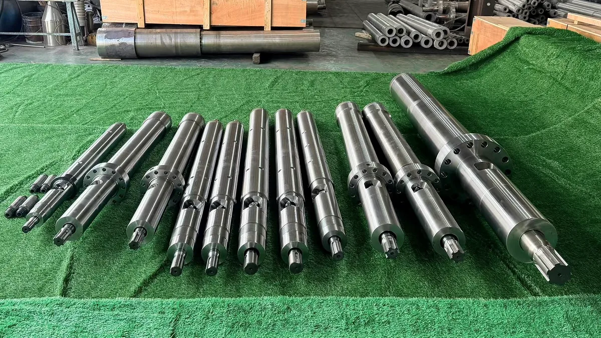
What Is Reciprocating Screw Injection Molding and Why It Matters
Reciprocating screw injection molding is a plastics manufacturing method in which a single helical screw performs two essential jobs: it plasticates (melts and homogenizes) the polymer, then drives axially forward like a ram to inject the molten material into a mold cavity. This dual-function design makes it the backbone of modern thermoplastic production, powering the vast majority of injection molding machines in operation worldwide.
If you've ever wondered how a single component can melt plastic and push it into a mold, the answer lies in the "reciprocating" action itself. The screw rotates to convey and melt resin, then stops spinning and shoots forward to fill the cavity. That back-and-forth motion is what separates this technology from every machine that came before it.
Defining the Reciprocating Screw Principle
At its core, every injection molding machine built on this principle follows the same cycle. Plastic pellets drop from a hopper into the barrel, where the rotating screw conveys them forward. As the material travels along the screw's helical flights, a combination of mechanical shearing and barrel heat transforms solid granules into a uniform melt. The screw simultaneously retracts, accumulating a precise "shot" of molten polymer ahead of its tip. Once enough material has gathered, the screw stops rotating and plunges forward, injecting the melt through a nozzle and into the mold cavity under high pressure.
The complete sequence looks like this: feed, rotate and recover, inject, hold pressure, cool, and eject. Each stage depends on the one before it, and the screw is the central player in most of them. You'll notice this makes the injection molding machine remarkably compact compared to systems that separate plasticating and injection into different units.
Why This Technology Became the Industry Standard
Before the reciprocating screw arrived, plunger-type machines dominated the landscape. These older systems relied on a heated torpedo inside the barrel to melt granules, but they had no real means of mixing or homogenizing the resin. The result was uneven melt temperatures, inconsistent shot quality, and a narrow range of processable materials.
A paradigm shift began in the 1950s when pioneers like William Willert developed the reciprocating screw concept. By the early 1960s, nearly every major injection molding machine manufacturer offered a screw-based press. The reason was simple: screw plasticating delivered a homogeneous melt with close temperature control and uniform viscosity, enabling up to 50% faster production rates than plunger systems. It also allowed lower injection pressures since the resin was fully melted before entering the mold, and it made material or color changes significantly faster.
The reciprocating screw simultaneously provides mechanical shearing, conductive heating, and pressure generation in one compact unit - replacing what previously required multiple components or stages.
This combination of melt uniformity, shot-to-shot consistency, and broad material versatility is why the reciprocating screw principle remains the dominant architecture in injection molding terminology and practice. Yet the screw itself is far from a simple component. Its geometry is divided into distinct functional zones, each engineered to handle a specific phase of the melting process - and understanding those zones is where most molders start gaining a real competitive edge.
Understanding the Three Functional Screw Zones in Plastic Injection Molding
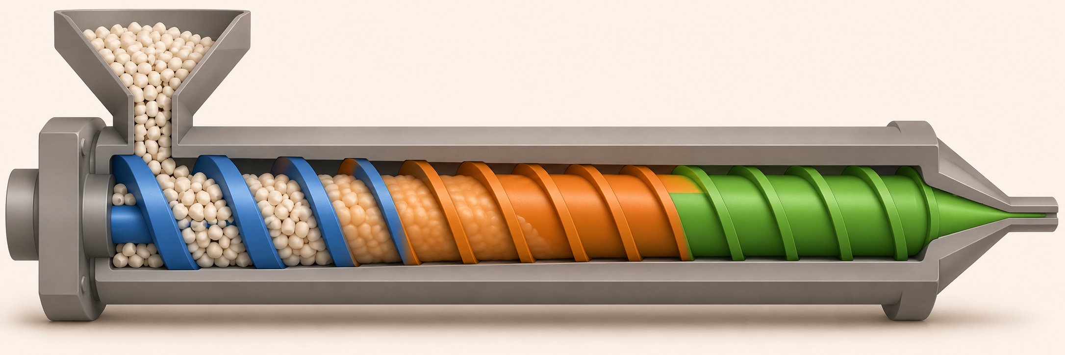
Picture a reciprocating screw sitting on a bench. It looks like one continuous helix, but functionally it's three machines welded end to end. Each zone has a distinct channel geometry, a specific job in the melting process, and a direct influence on the quality of every part that comes off your press. Misunderstand any one of them, and you'll chase defects that no amount of parameter tweaking can fix.
In plastic injection molding, every screw - whether general-purpose or application-specific - is divided into a feed zone, a compression (transition) zone, and a metering zone. The differences come down to channel depth, the energy applied to the resin, and the physical state of the polymer at each stage. Let's walk through them one at a time.
Feed Zone - Solids Conveying and Initial Heating
The feed zone is where everything starts. Pellets drop from the hopper into deep, constant-depth channels between the screw flights. The primary job here is deceptively simple: move solid granules forward consistently and begin warming them up.
What actually makes conveying work is a friction differential. The barrel wall is engineered to grip the pellets more than the screw root does. Imagine placing your hand on a conveyor belt - if the belt grabs your palm harder than the surface beneath your feet, you move forward. The same principle drives resin down the channel. Grooved feed throats and controlled barrel-wall temperatures enhance this friction advantage, while the screw root is often polished to reduce drag.
Why does this matter on the shop floor? If feeding is inconsistent - due to bridging in the hopper, moisture-swollen pellets, or an improperly cooled feed throat - every zone downstream inherits the problem. You'll see recovery-time variation, cushion drift, and shot-weight swings that make a plastic injection molding operator for toys or medical parts equally frustrated. Consistent pellet feeding is the foundation of downstream melt quality, and it depends almost entirely on the geometry and thermal management of this first section.
Compression Zone - Melting and Densification
This is where the real transformation happens. As the channel depth gradually decreases, solid pellets are squeezed against the hot barrel wall with increasing force. The shrinking channel accomplishes two things simultaneously: it compacts the loosely packed solids into a denser mass, and it dramatically increases the shear energy transferred into the material.
Here's how melting actually progresses. A thin film of molten polymer forms against the barrel wall. The rotating screw scrapes this film off and collects it into a "melt pool" on one side of the channel, while a shrinking "solid bed" remains on the other side. As the channel gets shallower, the solid bed narrows until - ideally - all material is fully melted by the time it exits this zone.
The interplay between shear heating and barrel conductive heating is critical. For high-viscosity resins, the barrel heaters do more of the heavy lifting. For lower-viscosity materials, internal shear generates the majority of thermal energy. Getting this balance wrong leads to either unmelted particles passing downstream or thermally degraded resin showing up as black specks and discoloration.
The compression ratio - defined as the ratio of feed zone channel depth to metering zone channel depth - is one of the most important screw specifications. Higher compression ratios increase shear heat, improve melt uniformity, and consume more energy, but they also raise the risk of degrading heat-sensitive plastics. Lower ratios are gentler but may leave material insufficiently melted. Selecting the right compression ratio for your polymer family is not optional - it's foundational.
Metering Zone - Homogenization and Pressure Building
By the time resin reaches the metering zone, it should be fully molten. This final section features a constant, shallow channel depth designed to do two things: homogenize the melt to a uniform temperature and viscosity, and build the pressure needed to push material through the non-return valve and into the mold.
Think of the metering zone as quality control before injection. Any remaining temperature gradients or viscosity inconsistencies get worked out here through continued shearing at a controlled, steady rate. The shallow channel ensures the melt experiences consistent residence time and energy input across every revolution. When the metering zone does its job well, you'll notice tighter shot-weight tolerances, fewer surface defects, and more predictable filling behavior - the kind of consistency that matters when you're tracking pareto analysis defect types injection molding quality data fields and trying to drive reject rates toward zero.
The length and depth of this zone vary depending on the screw design. A general-purpose screw allocates roughly equal lengths to all three zones, but specialty screws built for specific polymer families shift these proportions significantly. A screw optimized for semi-crystalline materials like nylon, for example, might use a longer compression zone to handle the sharper melting transition, while a screw for amorphous resins like polycarbonate could feature an extended metering zone for better homogenization.
Three Zones at a Glance
| Zone Name | Primary Function | Typical Relative Length (General-Purpose Screw) | Channel Depth Trend |
|---|---|---|---|
| Feed Zone | Solids conveying and initial heating | Approximately one-third of flighted length | Deep and constant |
| Compression (Transition) Zone | Melting, densification, and shear energy input | Approximately one-third of flighted length | Gradually decreasing |
| Metering Zone | Melt homogenization and pressure building | Approximately one-third of flighted length | Shallow and constant |
Keep in mind that this roughly equal 1:1:1 split applies to general-purpose screw designs intended for commodity resins like PP and PE. Specialty screws redistribute these proportions - sometimes dramatically - to match the thermal behavior and viscosity characteristics of specific polymer families. Always consult manufacturer data sheets for the exact zone geometry recommended for your primary resin.
These three zones work as an integrated system, and a problem in one ripples through the others. A feeding inconsistency becomes a melting inconsistency, which becomes a metering inconsistency - and ultimately a defective part. Yet the screw zones only tell half the story. The real art of reciprocating screw injection molding lies in how you set the process parameters that govern what happens inside each zone: back pressure, screw speed, barrel temperatures, and the often-overlooked details of decompression and cushion control.
How Process Parameters Interact During Plasticating and Injection
Here's a scenario every injection mold machine operator has lived through: you bump up back pressure to fix a mixing issue, and suddenly recovery time creeps up, melt temperature drifts higher, and a part that was running fine starts showing flash. You didn't change "everything" - you changed one setting. Yet the process responded as if you'd rewritten the entire setup sheet.
That's because plasticating and injection parameters don't operate in silos. They form an interconnected system where adjusting one variable shifts the behavior of several others. The question experienced molders ask isn't "What should I set this parameter to?" It's "How do I tune these settings together, not in isolation?" Answering that question is the difference between chasing defects and controlling a process.
Back Pressure and Screw RPM - Balancing Melt Quality Against Recovery Time
Back pressure is the resistance applied against the screw as it rotates and retracts during recovery. Think of it as a brake on the screw's rearward travel. The higher you set it, the harder the screw has to work to push material forward past the non-return valve and accumulate a shot. That extra effort translates into more shear energy, longer residence time in the barrel, and more thorough mixing of the melt.
Industry guidance from RJG recommends setting back pressure to approximately 500 to 1,000 psi specific (plastic pressure) for most applications. The purpose is consistency - compressing the melt ahead of the screw to ensure uniform density shot after shot. Go too low, and you'll get poorly mixed, low-density shots with air pockets, color streaks, and viscosity variation. Go too high, and the screw generates excessive shear heat, extends recovery time, and can degrade shear-sensitive polymers like PVC or POM.
Screw RPM works on the other side of the same equation. Faster rotation accelerates recovery, which sounds like a win for cycle time. But higher RPM also adds shear heat to the melt, sometimes substantially. When you pair high RPM with high back pressure, you're stacking two sources of energy input on top of each other. For robust commodity resins like PP or HDPE, this might be tolerable. For engineering-grade materials used in medical injection molding - think polycarbonate or PEEK - that excess thermal energy can push the polymer past its processing window and trigger degradation.
The practical balance looks like this: set back pressure high enough to achieve a dense, consistent shot with good color dispersion, then adjust screw RPM so that recovery finishes roughly 1.5 to 2 seconds before the cooling timer expires. If recovery finishes too early, material sits idle in the barrel and degrades. If it finishes too late, it forces extended cycle times and undermines consistency. The interplay between these two settings controls melt temperature, homogeneity, and cycle efficiency simultaneously - and adjusting one without considering the other almost always creates a new problem.
Barrel Temperature Profiles and Their Role in Shear-Conductive Heating Balance
A common misconception is that barrel heater bands "melt" the plastic. In reality, they supplement the shear energy generated by the screw. The barrel temperature you read on the controller represents the steel temperature, not the actual polymer temperature - and the two can differ by 20 to 40 degrees Fahrenheit depending on screw design, back pressure, and material viscosity.
For high-viscosity resins that resist flow, conductive heat from the barrel does more of the work because the polymer doesn't shear as easily. For low-viscosity resins, screw shear generates the lion's share of thermal energy, and barrel heaters mostly maintain a stable thermal environment. Understanding which energy source dominates for your material is essential to selecting the right temperature profile.
Three common barrel temperature strategies exist, each suited to different material behaviors:
- Ascending (ramp) profile: Temperatures increase from the feed zone to the nozzle. This is the most widely used approach, well suited for general-purpose resins like PP, PS, and ABS. It matches the screw's natural melting progression - gentle heating at the rear, full melt refinement at the front.
- Flat profile: All zones run at or near the same temperature. This works best for shear-sensitive materials like polycarbonate and PMMA, where the barrel simply needs to maintain a stable environment while the screw provides most of the melt energy.
- Reverse (humped) profile: The feed zone runs hotter, with temperatures stepping down toward the front. This is a specialty setup for high-viscosity resins or tacky pellets that slip in the feed section. Nylons (PA6, PA66) and glass-filled compounds sometimes benefit from this approach to stabilize solids conveying.
Choosing the wrong profile creates a cascade of issues. An aggressive ramp can overheat the front zone, causing drool and stringing at the nozzle. A flat profile on a material that needs progressive heating can leave unmelted particles in the shot. A reverse profile applied without cause can trigger bridging and screw starvation. The key is matching the profile to both the resin's thermal behavior and the screw's shear characteristics - not simply copying a setup sheet from a different machine or mold.
Decompression and Cushion - Protecting Shot Consistency
Two often-overlooked settings quietly govern whether all your careful back pressure, RPM, and temperature tuning actually translates into repeatable parts: decompression (suck-back) and cushion.
Decompression is the small rearward pull of the screw after recovery completes. Its purpose is to relieve pressure at the nozzle tip, preventing the melt from drooling or stringing into the mold between shots. Sounds straightforward, but the speed and distance of that pull matter enormously. Sucking back too quickly can cause splay by drawing air into the melt front. Sucking back too far can create a void at the screw tip and compromise the non-return valve's ability to seal during the next injection stroke. Too little decompression, and you get nozzle drool that fouls the sprue or creates cosmetic defects on the part surface.
Cushion is the small amount of melt that remains in front of the screw at the end of the injection and holding phases. It's typically a few millimeters of screw travel, and its consistency shot to shot is one of the most reliable indicators of process stability. A consistent cushion means the non-return valve is sealing properly, the shot volume is repeatable, and holding pressure is being effectively transmitted to the cavity.
When cushion varies - drifting up one shot, dropping the next - you'll see dimensional inconsistency, weight variation, and degraded surface quality. These symptoms often get blamed on temperature or pressure settings, but the root cause frequently traces back to a worn check ring, incorrect decompression, or an improperly sized shot relative to barrel capacity. In fields like medical injection molding, where dimensional tolerances are tight and every part must be traceable, cushion monitoring is not optional - it's a core process control metric. Even an injection mold cooling time calculation formula becomes meaningless if the shot entering the cavity isn't consistent to begin with.
Process parameters are a system - changing one always affects others. Back pressure, screw RPM, barrel temperatures, decompression, and cushion must be tuned as an integrated set, not adjusted in isolation.
This systems-level perspective is what separates experienced processors from those stuck in a cycle of reactive troubleshooting. Every parameter discussed here converges at one critical point: the screw tip, where the non-return valve must seal perfectly to preserve the shot you've worked so hard to prepare. A worn or damaged valve can undermine even the most precisely tuned process - and it's a failure mode that most molders don't catch until the damage shows up in their parts.
The Non-Return Valve and Its Role in Shot Consistency
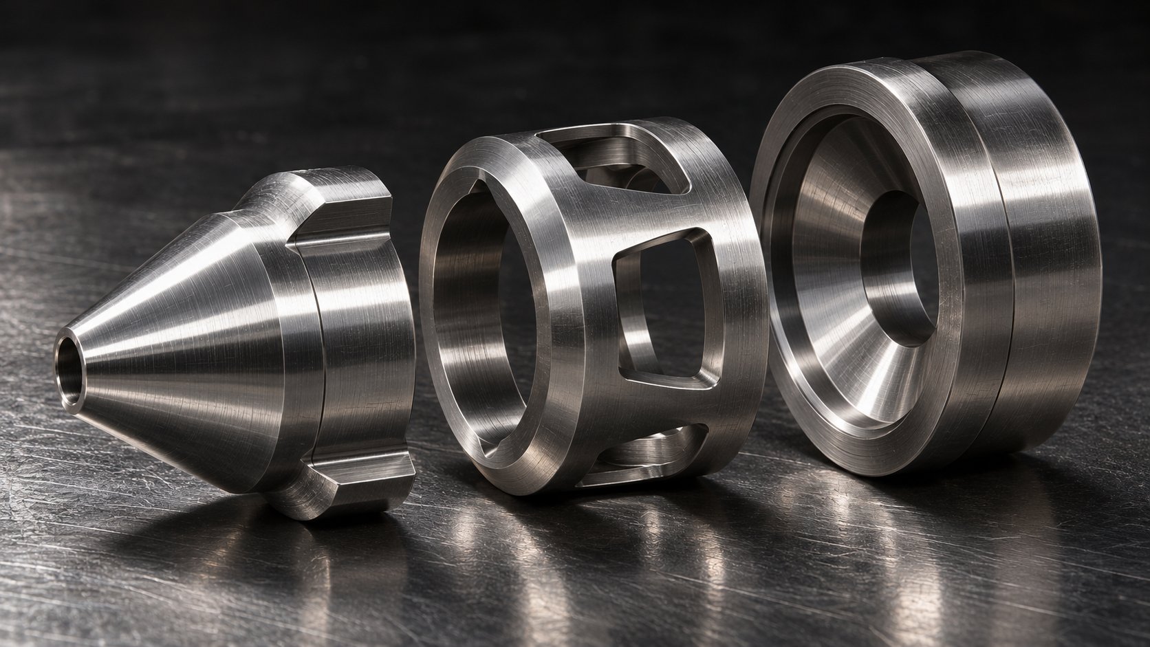
You can dial in flawless barrel temperatures, perfectly balanced back pressure, and textbook screw RPM - and still watch your process drift if one small assembly at the tip of the screw isn't doing its job. The non-return valve, commonly called the check ring, is arguably the most consequential wear component in the entire reciprocating screw injection molding system. It sits right at the boundary between plasticating and injection, and its condition determines whether the precise shot you've built actually reaches the mold intact.
Think of the check ring as a one-way gate. During recovery, it opens to let freshly melted polymer flow forward and accumulate in front of the screw. During injection, it slams shut to prevent that melt from leaking backward over the screw flights. When it works, you get repeatable shot volumes and stable cushion readings. When it doesn't, every downstream quality metric suffers - and the symptoms often mimic problems that have nothing to do with the valve itself.
How the Check Ring Functions During Recovery vs. Injection
The mechanical sequence is straightforward, but the demands on the valve are extreme. During screw rotation (recovery), the metering flights push molten plastic forward through the check ring assembly. This forward flow pressure slides the ring rearward, away from its seat, creating an open channel for the melt to pass through and accumulate ahead of the screw tip. The back pressure set on the machine - typically 500 to 750 psi plastic pressure for unfilled resins - determines how much resistance the melt encounters during this forward flow.
The moment injection begins, the dynamics reverse. The screw stops rotating and drives forward as a ram. Melt pressure ahead of the screw tip now pushes the ring forward against its seat, creating a seal that should prevent any polymer from flowing backward. Two seals must form simultaneously: one between the ring and its mating seat, and another between the ring's outer diameter and the barrel wall. The pressures involved are staggering - injection can generate 20,000 to 45,000 psi of plastic pressure when filling thin-walled parts.
Here's the critical point: the machine will execute the same screw movement every cycle regardless of whether the valve seals properly. If the ring doesn't close consistently, some melt escapes backward during injection, and the actual volume delivered to the mold changes - even though the machine's position readout looks identical. As Turner Group notes, modern machines control screw position, velocity, and pressure with exceptional precision, but that precision only translates into the molded part if the check ring closes predictably and seals consistently from cycle to cycle.
Common Non-Return Valve Designs
Not every check ring works the same way. The design you choose affects seal quality, flow restriction during recovery, sensitivity to specific materials, barrel wear rates, and maintenance complexity. Three primary categories cover the vast majority of applications in custom injection molding, blow injection molding, metal injection molding, and general thermoplastic processing:
- Sliding check ring (most common): A three- or four-piece assembly consisting of a retainer, a check ring, and a rear seat. During recovery, the ring slides rearward to allow flow. During injection, it slides forward against the seat to seal. Critically, the ring does not rotate with the screw - it only moves axially. This reduces barrel wall wear compared to rotating designs. Four-piece versions, which use a separate hardened front seat, tend to last longer and offer more material flexibility because the seat can be manufactured from a harder alloy than the retainer. For most applications, this style is the recommended starting point due to its versatility and durability.
- Ball check: Instead of a sliding ring, a ball or similar component floats inside the tip housing and plugs a flow hole during injection. The simplified internal geometry makes ball checks better suited for processing highly sensitive materials like polycarbonate and acrylic, and they provide a more positive shutoff with low-viscosity resins or very small shot sizes. The trade-off is that the sealing outer diameter rotates with the screw, which can accelerate barrel bore wear over time.
- Poppet valve (quick shut-off): A variation that uses a poppet or plug element to seal the flow path during injection. Poppet designs deliver exceptionally fast, positive shutoff characteristics, making them well suited for precision applications where even minor back-flow would compromise part quality. Like ball checks, however, their sealing surface typically rotates with the screw, introducing the same potential for increased barrel ID wear. These valves also tend to be more complex and costly to maintain.
A key distinction worth remembering: sliding check rings are the only common design where the sealing OD does not rotate with the screw. Locking-ring variants - popular with some machine OEMs - key the ring to the retainer so it rotates during plastication. While some molders believe this improves sealing, injection molding expert John Bozzelli has documented significant scoring and barrel damage from locking-ring rotation after as few as 2,000 hours of use, raising serious questions about their long-term cost-effectiveness.
Wear Indicators and Impact on Part Quality
Check ring wear doesn't announce itself with alarms. It develops gradually through normal production and accelerates with abrasive fillers, corrosive off-gases, or high processing speeds. As leakage increases, process consistency slowly deteriorates - making the problem easy to mistake for material variation, machine control drift, or changing mold conditions.
A worn check ring allows melt to flow backward over the screw flights during injection and pack-hold phases. The consequences show up across multiple quality metrics:
- Cushion variation: Shot-to-shot cushion position becomes erratic because varying amounts of melt escape past the worn seal each cycle.
- Short shots and inconsistent fill: Less material reaches the cavity than intended, especially on parts with thin walls or long flow lengths.
- Part weight variation: The actual delivered shot volume changes cycle to cycle, even though machine settings remain constant.
- Degraded holding-pressure effectiveness: Back-flow through the valve bleeds off the pressure meant to pack the cavity, leading to sink marks, voids, and dimensional instability.
One of the biggest dangers is that operators often compensate for these symptoms by adjusting pressures, positions, temperatures, or hold times. This can temporarily mask the underlying mechanical issue rather than correct it - widening the process window and making the root cause even harder to identify later.
Fortunately, several practical shop-floor checks can reveal a failing valve before it ruins a production run:
- Monitor cushion consistency: Track the screw position at the end of pack-hold over 20 to 30 consecutive shots. If the cushion drifts or shows excessive variation (beyond your normal process capability), the check ring is a prime suspect.
- Perform a rising-injection-pressure test: With the nozzle sealed against the sprue bushing or a purge cap, command the screw forward at a slow, constant velocity. A healthy check ring will allow pressure to build steadily and hold. A worn ring will show pressure that plateaus prematurely or drops off as melt leaks backward.
- Visual inspection during maintenance pulls: When the screw is pulled for scheduled service, examine the ring, seat, and retainer for scoring, galling, material buildup, and dimensional wear on the OD. Compare the ring's outer diameter against the known barrel bore dimension. Even a few thousandths of an inch of clearance growth can cause meaningful back-flow at injection pressures.
- Track part weight trends: A gradual increase in part weight standard deviation - even when all machine parameters remain locked - is a classic leading indicator of check ring deterioration.
The connection between check ring condition and overall process stability cannot be overstated. Every upstream effort - screw zone optimization, back pressure tuning, temperature profiling - funnels through this single valve. When it seals, your process runs like a Swiss watch. When it doesn't, you're fighting variability that no amount of parameter adjustment can fully correct.
Yet the non-return valve is just one part of the machine architecture story. The reciprocating screw design itself - with its integrated plasticating and injection functions - represents a specific engineering trade-off. Understanding how it compares to older plunger-type machines and more specialized two-stage systems reveals why most molders use it, and when a different architecture might actually be the better choice.
Reciprocating Screw Machines vs. Plunger and Two-Stage Systems
The reciprocating screw dominates modern thermoplastic production for good reason - but it isn't the only machine architecture available. Plunger-type machines preceded it, and two-stage systems evolved alongside it to serve applications where separating the plasticating and injection functions offers a measurable advantage. If you're evaluating press equipment for a new line, expanding capacity, or troubleshooting limitations on an existing machine, understanding where each architecture excels - and where it falls short - helps you make decisions based on engineering rather than habit.
Most injection molding companies default to the reciprocating screw without considering alternatives. In many cases, that's the right call. In some cases, it isn't. Here's how the three architectures actually compare.
Reciprocating Screw vs. Plunger-Type Machines
Plunger-type injection machines are the oldest architecture in the industry, and their design is fundamentally different from anything screw-based. There is no helical screw at all. Instead, a hydraulic plunger rams solid granules forward through a heated barrel fitted with a torpedo-shaped spreader (sometimes called a split shuttle or flow divider). This torpedo sits inside the barrel cavity and forces the material to flow around it in thin layers, picking up heat from the barrel wall through conduction as it passes.
Sounds simple - and it is. That simplicity comes with serious trade-offs:
- Poor melt uniformity: Because there's no screw to generate shear energy, the resin relies almost entirely on conducted heat from the barrel and torpedo. The result is significant temperature gradients within the shot - hot material near the barrel wall, cooler material in the center. You'll see this show up as inconsistent fill, surface defects, and unpredictable shrinkage.
- High injection pressure losses: The plunger must push unmelted and partially melted granules forward through the torpedo's narrow flow channels. As industry sources note, resistance from compacting material, navigating the torpedo, and filling the cavity all stack up, making it difficult to fill complex or thin-walled parts consistently.
- Uneven injection speed: The plunger first compacts the granules before any melt actually moves toward the mold. This creates a lag between screw motion and actual melt flow, unlike the nearly immediate response you get from a reciprocating screw acting on a fully molten, pre-metered shot.
- Limited material range: Without mechanical mixing, materials that require thorough blending - color concentrates, additives, multi-component compounds - simply can't be processed to an acceptable standard.
Does anyone still use plunger machines? Yes, but primarily in thermoset molding, rubber processing, and some structural foam injection molding applications where the material chemistry or process requirements favor a simpler, high-force delivery mechanism. For thermoplastic production, plunger systems are essentially obsolete. Even small-tonnage operations have migrated to screw-based presses because the improvement in melt quality and repeatability is too significant to ignore.
Reciprocating Screw vs. Two-Stage Systems
Two-stage machines take the opposite approach from plungers - they don't simplify the system, they split it apart. Instead of one screw doing double duty, a two-stage (shot-pot) machine uses a rotating screw exclusively for plasticating and a completely separate hydraulic plunger for injection. The screw melts and homogenizes resin continuously, feeding it into a second metering chamber. Once the chamber fills to a precise volume, a high-speed piston drives the melt into the mold.
This architecture eliminates one of the inherent compromises in reciprocating screw design: the fact that the same component must both melt the plastic and inject it. By decoupling those functions, two-stage systems unlock several advantages that matter in demanding applications:
- Independent process optimization: Screw speed and temperature can be tuned purely for melt quality without any concern about injection dynamics. The piston handles filling independently, at whatever speed and pressure profile the part requires.
- Exceptional shot consistency: Because the metering chamber is filled to a precise volume and the piston has no check ring to leak past, shot-to-shot repeatability is outstanding. Micro-molding specialist Matrix Plastic Products found this advantage critical when molding ultra-thin-walled medical components where even minor shot variation caused undetectable short shots - a failure mode they traced directly to check ring leakage on conventional reciprocating screw presses.
- Very large shot capacities: Two-stage machines can accumulate larger shot volumes than a single-screw machine of comparable barrel diameter, making them well suited for automotive injection molding and other large-part applications where high shot weights are routine.
- Reduced shear on sensitive materials: Since the feed screw isn't making high-speed axial movements, it generates less excess shear heat. The material follows a more reliable first-in, first-out path, and the absence of a check ring eliminates the back-flow and shear variability that valve wear introduces over time.
The downsides? Two-stage machines cost more, occupy a larger footprint, and introduce additional material residence time in the shot-pot chamber. That extra residence can be problematic for heat-sensitive resins that degrade with prolonged exposure to processing temperatures. They also add mechanical complexity - more seals, more moving parts, more maintenance touchpoints. For the vast majority of production applications, the reciprocating screw offers the best balance of performance, versatility, and cost-effectiveness.
Where two-stage systems truly shine is at the extremes: micro-molding where check ring leakage is intolerable, very large parts where shot volumes exceed single-screw capacity, and precision applications where independent plasticating and injection control justifies the added investment.
Side-by-Side Comparison Table
| Machine Type | Melt Quality | Shot Consistency | Material Versatility | Energy Efficiency | Typical Applications | Relative Cost |
|---|---|---|---|---|---|---|
| Reciprocating Screw | Excellent | Good to Excellent | Excellent | Good to Excellent | General thermoplastics, automotive injection molding, consumer products, medical, packaging | Moderate |
| Two-Stage (Shot-Pot) | Excellent | Excellent | Good | Good | Micro-molding, very large parts, precision medical and optical components | High |
| Plunger-Type | Fair | Fair | Limited | Fair | Thermoset molding, rubber, structural foam injection molding, legacy applications | Low to Moderate |
A few notes on interpreting the table. The reciprocating screw's "Good to Excellent" shot consistency rating reflects the reality that check ring condition directly affects repeatability - a well-maintained valve delivers excellent results, while a worn one degrades performance noticeably. Two-stage machines earn a straight "Excellent" because their plunger-and-chamber design eliminates that variable entirely. The plunger machine's "Limited" material versatility acknowledges that it simply cannot mix or homogenize resins the way any screw-based system can.
Energy efficiency also varies within each category. All-electric reciprocating screw machines rival or exceed two-stage systems in energy performance, while hydraulic versions of both architectures consume more power. The specific drive technology - hydraulic, hybrid, or fully electric - matters as much as the plasticating architecture when evaluating total operating cost.
For most injection molding companies, the reciprocating screw remains the clear default: versatile enough for nearly any thermoplastic, compact, cost-effective, and supported by the widest ecosystem of tooling, training, and replacement parts. The two-stage system is a specialist's tool, justified when your application demands it. The plunger is a legacy design that still earns its place in thermoset and rubber work but offers little advantage for modern thermoplastic processing.
Choosing the right machine architecture is only half the equation, though. Even within the reciprocating screw family, the screw itself must be matched to the specific polymer you're running. Semi-crystalline and amorphous resins, shear-sensitive compounds, and abrasive glass-filled materials each demand different screw geometries, compression ratios, and wear-resistant construction - and a general-purpose screw compromises performance on all of them.
Material-Specific Screw Design and Processing Considerations
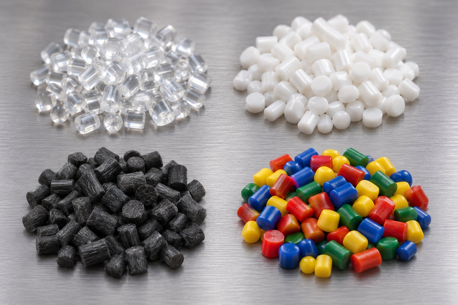
A general-purpose screw is a compromise - and like most compromises, it does nothing exceptionally well. It runs commodity resins acceptably, but the moment you switch to a semi-crystalline engineering resin, a shear-sensitive compound, or a glass-filled formulation, that "good enough" screw starts costing you money in longer cycles, higher scrap rates, and inconsistent part quality.
The reason is simple: different polymer families behave fundamentally differently as they melt. Some soften gradually. Others stay rock-hard until they hit a precise temperature, then melt almost instantly. Some degrade if you look at them wrong, while others chew through hardened tool steel like sandpaper. Every plastic injection molding company running more than one material family needs to understand how screw geometry and process strategy must shift to match what's actually in the barrel.
Consider this section a practical reference you can return to whenever a new resin shows up on your production schedule.
Amorphous vs. Semi-Crystalline Polymers
This is the most fundamental divide in polymer processing, and it has a direct, measurable impact on screw selection.
Amorphous resins - ABS, polycarbonate (PC), polystyrene (PS), PMMA - have randomly oriented polymer chains. As injection molding expert John Bozzelli explains, these materials soften progressively as they warm up, much like frozen butter left on a countertop. There's no sharp melting point. A partially melted amorphous pellet is soft and pliable, almost taffy-like, meaning it won't damage the screw or barrel if it gets wedged between a flight and the barrel wall. This forgiving melt behavior allows amorphous resins to process well with moderate compression ratios, typically in the range of 2.0:1 to 2.5:1. The screw doesn't need to work as aggressively to achieve a uniform melt.
Semi-crystalline resins - polyethylene (PE), polypropylene (PP), nylon (PA), PBT, POM - are a different animal entirely. Their polymer chains are arranged in ordered crystalline structures, and those structures don't break down gradually. Instead, semi-crystalline pellets stay hard until they absorb enough energy to reach their melting point and overcome the heat of fusion needed to disrupt the crystal lattice. Bozzelli puts this in perspective: nylon 6 requires roughly twice the energy to melt as ABS - about 716 BTU/kg versus 342 - yet both process at similar barrel temperatures.
What does this mean for screw design? Semi-crystalline resins need higher compression ratios - commonly 2.5:1 to 3.5:1 - to generate enough shear energy in the compression zone to overcome that energy barrier. They also benefit from longer transition zones because the solid-to-liquid phase change happens abruptly. If the compression zone is too short, solid bed breakup occurs: chunks of unmelted pellets break free and travel through the metering zone, potentially ending up in your finished part. On a desktop injection molding machine running small shots, you might get away with a general-purpose screw on PE. On a production press running 50% barrel capacity with nylon, you almost certainly won't.
Shear-Sensitive and Heat-Sensitive Materials
Some resins don't just melt differently - they degrade if the screw applies too much mechanical or thermal energy. These materials demand specialized screw geometries that a general-purpose design simply cannot provide.
PVC is the textbook example. When overheated or subjected to excessive shear, PVC releases hydrochloric acid (HCl) gas, which corrodes barrel and screw surfaces while degrading the polymer into a discolored, brittle mess. Processing PVC successfully requires a low-compression screw - typically around 1.5:1 to 2.0:1 - with streamlined flow paths that minimize dead spots where material could stagnate and overheat. Screw and barrel metallurgy must resist corrosive wear from HCl attack, which aggressively destroys components with high iron content. Many PVC processors specify corrosion-resistant alloy barrel liners and chrome-plated or nitrided screws specifically for this reason.
POM (acetal) presents a different hazard. When POM degrades, it generates formaldehyde gas, creating both a quality issue and a workplace safety concern. Careful temperature control - avoiding hot spots and excessive residence time - is non-negotiable. Screw designs for POM prioritize gentle, uniform heating with minimal dead zones. Even the non-return valve geometry matters: areas where material can stagnate and overheat become potential degradation sites.
PC and PMMA are shear-sensitive in a different way. Both require relatively high melt temperatures but are prone to developing splay, yellowing, or molecular weight reduction if shear energy is applied too aggressively. A flat barrel temperature profile often works better than an ascending ramp, and screw designs with strong mixing capability in the metering zone - rather than relying on brute-force compression - help achieve optical clarity without thermal damage.
The takeaway? Imagine running PVC on a screw designed for polypropylene. The high compression ratio would generate excessive shear heat, the unoptimized flow path would create stagnation points, and within hours you'd have corroded metal surfaces and degraded resin. General-purpose screws compromise performance on every sensitive material they touch - and in injection blow molding or medical applications where material integrity is critical, that compromise becomes a liability.
Filled, Reinforced, and Abrasive Compounds
Glass-fiber-reinforced nylons, mineral-filled polypropylenes, and carbon-fiber composites introduce a completely different set of challenges. The fillers themselves - hard, angular particles suspended in the polymer melt - act as abrasives that accelerate wear on every metal surface they contact.
Industry data from Glycon Corp. confirms that some of the most aggressive fillers can reduce screw and barrel useful life by 50% or more compared to unfilled resin processing. The wear mechanism is primarily abrasive: hard filler particles scrub against flight lands, the barrel bore, and the non-return valve, gradually increasing clearances and degrading melting efficiency. Glass fibers are especially damaging because they combine hardness with a needle-like geometry that concentrates wear forces.
Protecting against this wear requires upgraded metallurgy across the entire plasticating system:
- Bimetallic barrels: Centrifugally cast barrel liners with high tungsten carbide content resist abrasive wear far longer than standard nitrided steel.
- Tool-steel or hardfaced screw flights: Flight lands are the first point of contact between abrasive fillers and the screw. Hardfacing alloys with high carbide content dramatically extend flight life, though alloy selection must be compatible with the barrel lining material to avoid adhesive wear from incompatible metals.
- Specialized mixing elements: Distributive mixing sections (pin mixers, pineapple mixers) help achieve uniform filler dispersion without excessive fiber breakage. For glass-fiber compounds, maintaining fiber length is critical to part strength - an overly aggressive mixing design that disperses filler well but snaps fibers in half defeats the purpose of reinforcement.
Compression ratios for filled compounds generally fall in the moderate range (2.0:1 to 2.8:1), high enough to ensure thorough melting and wetting of the filler but not so aggressive that fiber damage or excessive wear occurs. The L/D ratio matters here too - longer screws (22:1 to 24:1) provide more residence time for heat transfer and filler wetting without requiring destructive levels of shear.
Material Family Quick-Reference Table
| Material Type | Recommended Compression Ratio Range | Screw Design Notes | Key Process Considerations |
|---|---|---|---|
| PE, PP (semi-crystalline commodity) | 2.5:1 to 3.5:1 | Higher compression to overcome heat of fusion; consider barrier flights for large shots | Solid bed breakup risk; avoid undersized shot relative to barrel capacity |
| PA (nylon) | 2.5:1 to 3.5:1 | Extended transition zone; barrier screw preferred for melt uniformity | High energy demand (~2x amorphous); moisture control critical; reverse temperature profile may help |
| ABS, PS (amorphous commodity) | 2.0:1 to 2.5:1 | General-purpose geometry often acceptable; mixing section improves color dispersion | Forgiving melt behavior; ascending temperature profile typically suitable |
| PC, PMMA (amorphous engineering) | 2.0:1 to 2.5:1 | Strong metering-zone mixing for optical clarity; avoid dead spots | Shear-sensitive; flat temperature profile preferred; splay risk at high RPM |
| PVC | 1.5:1 to 2.0:1 | Low-compression, streamlined flow path; corrosion-resistant metallurgy required | Releases HCl on degradation; minimize residence time and stagnation zones |
| POM (acetal) | 2.0:1 to 2.5:1 | Smooth flow paths; no dead zones in tip assembly; moderate compression | Formaldehyde generation risk; tight temperature control; avoid overheating |
| Glass-fiber / mineral-filled compounds | 2.0:1 to 2.8:1 | Bimetallic barrel; hardfaced flights; distributive mixing to preserve fiber length | Accelerated abrasive wear; monitor screw/barrel clearances frequently; L/D of 22:1 to 24:1 preferred |
Note: The compression ratios and design recommendations above represent general industry guidance. Always reference the resin manufacturer's processing data sheet for specific recommendations tailored to your exact grade and formulation.
Matching screw geometry to your polymer family is one of the highest-impact decisions you can make in reciprocating screw injection molding - yet it's one that many processors skip entirely, defaulting to whatever general-purpose screw shipped with the machine. The performance gap between a properly matched screw and a generic one shows up in every metric that matters: cycle time, melt quality, energy consumption, and component wear life. And as screw technology continues to evolve - with barrier flight designs, advanced mixing elements, and high-performance coatings - the gap between "good enough" and optimized only keeps widening.
Modern Screw Technology and Energy Efficiency Advances
The general-purpose, three-zone screw hasn't changed much since the 1960s - but the demands placed on injection molding of plastics certainly have. Tighter tolerances, faster cycles, more challenging resin formulations, and relentless pressure on energy costs have pushed screw designers well beyond the classic feed-compress-meter formula. If you're still running the same screw geometry your machine shipped with a decade ago, you're leaving performance on the table - and quite possibly burning more energy per kilogram of resin than you need to.
Three areas of advancement deserve attention: barrier flight and mixing element designs that improve melt quality at the screw level, wear-resistant coatings and alloys that extend component life, and the shift from hydraulic to electric screw drives that's reshaping how machines consume power.
Barrier Flights and Mixing Elements
Imagine the compression zone of a conventional screw. As the solid bed narrows and a melt pool forms, there's nothing physically separating the two. Unmelted chunks can break free from the solid bed, bypass the remaining compression zone, and reach the metering section - showing up as unmelted particles in your finished part. Barrier screw designs solve this problem elegantly by introducing a secondary flight that runs parallel to the main flight, creating two distinct channels: one for solids and one for melt. Only fully molten polymer can cross the barrier flight's clearance gap, ensuring that the material exiting the barrier section is completely melted.
The concept originated with Geyer's work at Uniroyal in 1961 for rubber processing, and within about a decade, barrier screws had established their position in thermoplastic processing. Common barrier designs include the Maillefer-type and various proprietary geometries, each with slightly different approaches to how the solid and melt channels taper along the screw length. For semi-crystalline resins like PE, PP, and nylon - where the sharp melting transition makes solid bed breakup a persistent risk - barrier screws deliver a measurably more uniform melt than any conventional three-zone design.
Mixing elements add another layer of melt quality control, and choosing the right type depends entirely on what you need to accomplish. The two fundamental categories are dispersive and distributive:
- Dispersive mixing elements (Maddock/LeRoy, blister rings) force the melt through narrow clearances under high shear. They're designed to break apart agglomerates, unmelted particles, or gels - anything that shouldn't be there. The original Maddock and Egan mixers, developed in the late 1960s, were specifically created to improve melt quality in conventional screws processing crystalline polyolefins, and they delivered immediate improvements in both output and homogeneity.
- Distributive mixing elements (pin mixers, pineapple mixers, Saxton-style mixers) split and recombine the melt stream repeatedly without applying aggressive shear. They're ideal for blending color concentrates, dispersing additives uniformly, and homogenizing temperature gradients. Pineapple mixers, for example, divide the melt and recombine it at different angles, creating chaotic mixing patterns that are especially effective for color distribution.
Here's a detail that often surprises processors: barrier screws with properly designed barrier sections shouldn't need a high-shear dispersive mixer downstream. As industry analysis points out, once material has passed through a well-designed barrier section, it should already be fully molten. Adding a dispersive mixer after the barrier frequently raises melt temperature unnecessarily, reduces output due to added pressure drop, and increases energy consumption. In most cases, a distributive mixer is the better complement to a barrier screw - it homogenizes temperature and additive distribution with minimal thermal penalty.
This distinction matters for pareto analysis defect types injection molding quality control. If your top defects include color streaks, splay from unmelted particles, or surface imperfections from gels, the fix may not be a process parameter change at all - it may be specifying the right mixing element for your screw design.
Advanced Coatings and Wear-Resistant Alloys
Even the best screw geometry loses its effectiveness as metal wears away. And in a production environment running abrasive glass-filled compounds or corrosive PVC, that wear happens faster than most maintenance schedules anticipate. Modern metallurgy and surface treatments give processors real options for extending plasticizing component life - often by multiples of what standard tool steel delivers.
On the barrel side, bimetallic liners remain the gold standard for abrasion resistance. These liners are centrifugally cast inside the barrel bore from alloys with high tungsten carbide or boron content, creating a wear surface far harder than the base steel. For corrosive resins like PVC, nickel-based alloys provide chemical resistance that standard iron-rich steels simply cannot match.
Screw surface treatments span a wide spectrum, each suited to specific wear mechanisms:
- Nitriding: A heat-treatment process that hardens the screw surface. Relatively inexpensive and effective for general-purpose processing, but limited against heavily abrasive fillers.
- Chrome plating: Provides good corrosion resistance and a smooth surface finish that reduces material adhesion. Common on PVC screws where corrosive attack is the primary concern.
- Tungsten carbide coatings: Applied to flight lands and other high-wear areas, these coatings dramatically extend life when processing glass-fiber-reinforced or mineral-filled compounds.
- Proprietary alloy overlays: Weld-applied hardfacing alloys on flight tips and bearing surfaces offer the highest wear resistance for the most demanding applications - though compatibility with the barrel liner alloy must be verified to prevent adhesive wear between mismatched metals.
The economics are straightforward. A coated or hardfaced screw costs more upfront but lasts significantly longer when matched to the right application. For processors running filled or corrosive materials, the cost of premature screw replacement - including downtime, production losses, and degraded part quality as clearances open up - almost always exceeds the incremental cost of wear-resistant construction.
Electric vs. Hydraulic Screw Drives
The screw itself isn't the only component evolving. How the screw is driven - the motor and transmission system that rotates it during recovery and pushes it forward during injection - has undergone a fundamental shift over the past two decades. Traditional hydraulic systems are giving ground to all-electric servo drives and hybrid configurations, and the trend is accelerating for good reason.
In a hydraulic machine, oil-driven motors handle screw rotation and a hydraulic cylinder provides injection force. The system works, but it's inherently inefficient: the hydraulic pump runs continuously (or at least at high idle) even when no motion is required, and energy lost as heat in the hydraulic oil must be removed by cooling systems. For applications like large part injection molding, hydraulic machines still hold an edge - hydraulic systems deliver bursts of power and clamp pressure that electric machines struggle to match, and accumulators provide rapid energy surges for fast-fill applications.
All-electric machines replace every hydraulic actuator with servo motors and ball-screw or toggle mechanisms. The result is a machine that only consumes energy when something is actually moving. Research confirms that all-electric machines use less energy per cycle than hydraulic counterparts on the same part, regardless of machine size - a finding that holds even on larger presses above 800 tons. The precision of servo-driven screw control also translates into tighter shot-to-shot repeatability: the motor can position the screw to fractions of a millimeter and modulate rotation speed with near-instantaneous response.
Key benefits of electric screw drives include:
- Energy efficiency: Servo motors consume power only during active motion phases, reducing per-cycle energy use significantly compared to continuously running hydraulic pumps.
- Repeatability: Precise servo control of screw speed, position, and injection velocity delivers tighter process windows and more consistent part quality.
- Lower noise: No hydraulic pump means dramatically quieter operation - an increasingly valued feature in modern manufacturing facilities.
- Reduced maintenance: Eliminating hydraulic oil removes an entire maintenance system: no filter changes, no oil temperature management, no leak remediation.
- Cleanroom suitability: The absence of hydraulic fluid eliminates contamination risk, making all-electric machines the preferred choice for medical and food-contact applications.
The tradeoff? Cost and scale. All-electric machines carry a higher purchase price, and above 1,000 tons most manufacturers don't offer all-electric models - not because hydraulics are more efficient at that size, but because servo drives and mechanical components become disproportionately larger, costlier, and harder to engineer as tonnage grows. Hybrid machines, which pair electric plasticating drives with hydraulic clamp units, bridge the gap for mid-range and larger applications.
When evaluating thermoforming vs injection molding or comparing different press technologies, the drive system is often an overlooked variable. Yet it directly affects energy cost per part, process repeatability, maintenance burden, and facility requirements. The industry trend is clearly moving toward hybrid and fully electric platforms - and for processors focused on total cost of ownership rather than just purchase price, the math increasingly favors electric drives for machines under 1,000 tons.
All of these advancements - barrier flights, mixing elements, wear-resistant coatings, and electric drives - ultimately serve the same goal: getting more consistent, higher-quality melt into the mold while consuming fewer resources. But even the most advanced screw technology has a finite service life. Knowing when your plasticating components have crossed the line from "performing" to "costing you money" - and having a clear maintenance and replacement strategy - is what keeps these gains from eroding over time.
Screw and Barrel Maintenance, Wear Diagnosis, and Replacement
Here's a frustrating reality most molders have lived: a process that ran flawlessly for months starts drifting. Recovery time creeps up. Cushion readings bounce around. Part weights wander outside spec. The instinct is to chase parameters - bump temperatures, tweak back pressure, adjust hold times. And for a while, those compensations work. Then they stop working too, and you're left wondering what changed when nobody touched the setup sheet.
More often than not, the answer is hiding inside the barrel. Screw and barrel wear doesn't fail like a blown fuse - it degrades gradually, mimicking process instability that operators understandably attribute to material variation, temperature drift, or controller issues. Recognizing wear patterns early, maintaining a disciplined inspection protocol, and knowing when to replace versus continue running are the skills that separate reactive troubleshooting from proactive injection molding equipment management.
Recognizing Screw and Barrel Wear Patterns
Wear inside the plasticating unit rarely announces itself with an obvious symptom. Instead, it shows up as subtle shifts in process behavior that accumulate over weeks or months. The challenge is distinguishing wear-related drift from the dozens of other variables that can change process performance.
Several key indicators, when they appear together or worsen progressively, point toward mechanical deterioration rather than material or setting issues:
- Increasing recovery time: As TAN STAR Industries documents, a gradual increase in screw recovery time - even when resin, RPM, back pressure, and heater performance remain stable - suggests that conveying and compression efficiency inside the barrel have deteriorated. Enlarged clearance between the screw flights and barrel wall allows more melt to slip backward across the flights instead of being driven forward, forcing the screw to work harder and longer to prepare the same shot volume.
- Rising melt temperature at constant settings: Worn clearances change the shear dynamics inside the barrel. Material that leaks past widened flight gaps gets sheared repeatedly, adding thermal energy that wasn't there when the components were new. You'll notice this as a slow upward drift in actual melt temperature - measured at the nozzle with a pyrometer, not read from the barrel controller - even though heater setpoints haven't changed.
- Growing cushion variation: Shot-to-shot cushion position should remain tight on a healthy machine. When barrel wear opens up screw-to-barrel clearance, and check ring wear compounds the problem, the amount of melt that flows backward during injection becomes unpredictable. Cushion readings start bouncing, and with them, part weight and dimensional consistency.
- Visible scoring or galling during maintenance pulls: Physical evidence tells the definitive story. Longitudinal scratches (scoring) on the barrel ID or screw flight surfaces indicate hard contaminant damage or metal-to-metal contact. Galling - rough, torn metal surfaces where material has welded and torn away - signals adhesive wear from excessive contact pressure or metallurgical incompatibility between screw and barrel surfaces.
- Declining part weight consistency: When Santa Fe Machine Works describes this symptom, they frame it clearly: a worn feed screw may develop dead zones or reduced compression efficiency, leading to poor melt quality, material degradation, and slippage. The net effect is that each shot delivers a slightly different volume of polymer to the mold - even though the machine's position control is doing its job perfectly.
Understanding why these symptoms develop requires recognizing that screw and barrel wear isn't one mechanism - it's at least three, and each leaves a different signature:
- Abrasive wear: Caused by hard filler particles - glass fibers, mineral powders, carbon fiber - scrubbing against metal surfaces. This is the most common wear mechanism in injection molding services that process reinforced compounds. It uniformly enlarges the barrel bore and reduces screw flight OD over time, gradually increasing the clearance that determines conveying and sealing efficiency.
- Adhesive wear: Metal-to-metal contact between the screw flight lands and the barrel wall. This happens when clearance becomes so tight (or when deflection occurs under load) that the two surfaces touch, weld momentarily at microscopic contact points, and tear apart. The result is galling damage that accelerates rapidly once it starts.
- Corrosive wear: Acidic off-gases from thermal degradation attack the barrel and screw surfaces chemically. PVC processing is the classic example - HCl released during degradation aggressively corrodes components with high iron content. But flame-retardant additives, certain colorants, and even moisture reacting with some polymers at processing temperatures can create corrosive conditions that pit and erode metal surfaces from the inside out.
The important insight is that these mechanisms often combine. A barrel processing glass-filled nylon, for instance, faces simultaneous abrasive wear from the glass fibers and potential corrosive attack from moisture-driven hydrolysis at elevated temperatures. Addressing only one mechanism when replacing components means the next set of parts may wear out just as quickly.
Preventive Maintenance Best Practices
The most expensive maintenance event is the one you didn't see coming. Unplanned downtime forces rushed decisions - expedited parts orders, emergency screw pulls during production hours, and process revalidation that eats into delivery schedules. As Plastics Technology emphasizes, a structured preventive maintenance approach doesn't have to be complex to deliver real benefits. It just has to be consistent.
For reciprocating screw injection molding systems, a practical maintenance protocol built around the plasticating unit looks like this:
- Track recovery time and cushion trends as leading indicators. These are your earliest warning signals. Log recovery time and cushion position (minimum, maximum, and standard deviation) at regular intervals - weekly for high-volume production, monthly for lower utilization. Plotting these values over time reveals gradual drift long before it becomes a quality problem. A machine that previously recovered in 8.5 seconds consistently but now takes 9.5 seconds - with no changes in resin, RPM, or back pressure - is telling you something about internal clearances.
- Perform scheduled screw pulls at defined intervals based on resin abrasiveness. Industry guidance suggests pulling the screw at least once a year for inspection against the manufacturer's recommended dimensional requirements. For machines running glass-filled or mineral-filled compounds, shorten that interval to every six months or even quarterly. Abrasive resins don't respect calendar schedules - they wear metal based on throughput and filler loading.
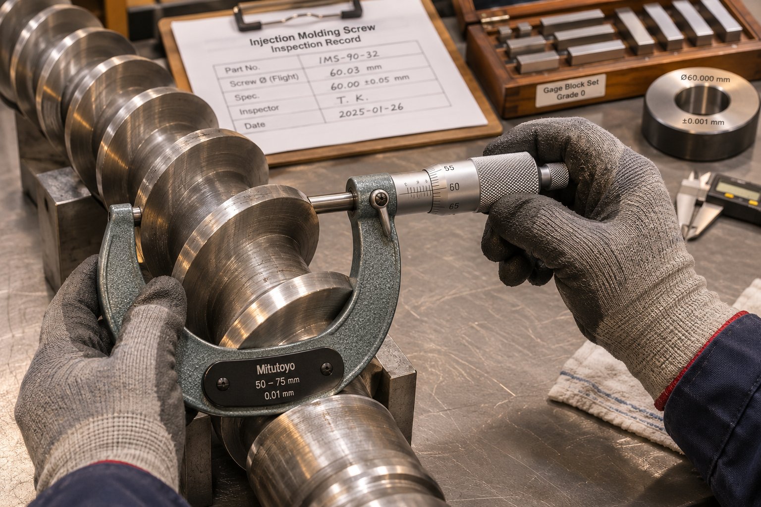
- Measure screw flight OD and barrel ID with calibrated instruments. This is the objective check that removes guesswork. Use a telescoping bore gauge or inside micrometer for the barrel, and an outside micrometer for the screw flight OD. Compare measurements against the manufacturer's original specifications and record them in a tracking log. What you're watching for is the trend: a barrel that started at 40.00 mm and now measures 40.08 mm has lost meaningful sealing capability, even though the numbers sound small.
- Inspect the non-return valve for ring wear, seat damage, and proper seating. During every screw pull, disassemble the check ring assembly and examine each component individually. Look for scoring on the ring OD, wear grooves on the seat face, and material buildup that could prevent the ring from sliding freely. Measure the ring OD against the known barrel bore to quantify the seal gap. A check ring that doesn't seal properly can undermine every other aspect of your process, as discussed in the previous section on shot consistency.
- Document wear measurements over time to predict replacement needs. A single measurement tells you where things stand today. A series of measurements tells you when you'll need to act. By plotting flight OD, barrel ID, and check ring dimensions over time, you can extrapolate wear rates and schedule replacements during planned downtime rather than reacting to failures. This is especially valuable for injection molding equipment running multiple resin families, where wear rates differ significantly between materials.
A previously stable process that requires increasingly frequent adjustment - even though resin, mold, and basic production conditions haven't changed - is one of the strongest indicators that the plasticizing system needs physical inspection, not more parameter compensation.
One more practical point: always evaluate the screw and barrel as a matched system. Replacing only the screw while leaving a worn barrel in place - or vice versa - can leave the underlying clearance problem unresolved. As TAN STAR notes, a new screw running inside a heavily worn barrel may not provide the intended clearance and performance. Inspect both components together and make replacement decisions based on the system, not individual parts.
When to Replace or Upgrade Plasticizing Components
At some point, maintenance transitions from monitoring to decision-making: keep running, or replace? The answer depends on measurable criteria, not gut feel.
Worn screws and barrels don't just degrade part quality - they cost you money in less obvious ways. Enlarged clearances reduce conveying efficiency, forcing longer recovery times that extend cycle time. The machine's heaters work harder to compensate for degraded plasticating performance, increasing energy consumption per shot. Wider process windows mean more scrap, more operator intervention, and more downstream quality holds. When you add up these hidden costs, continuing to run worn components is often more expensive than replacing them - you're just paying the price incrementally rather than in one line item.
A practical decision framework looks like this:
| Measured Condition | Recommended Action |
|---|---|
| Dimensions within spec; process stable and consistent | Continue operation with periodic monitoring |
| Early dimensional wear detected; process still within acceptable range | Increase monitoring frequency; plan replacement budget |
| Noticeable clearance increase with growing cushion variation or recovery drift | Measure both screw and barrel; schedule replacement during planned downtime |
| Severe scoring, corrosion, or dimensional wear beyond manufacturer tolerances | Replace screw and barrel as a matched set |
| Repeated process instability despite correct settings; frequent operator compensation required | Immediate inspection and likely replacement |
Here's where replacement becomes an opportunity rather than just an expense. If the original screw was a general-purpose design - and you've since shifted your production mix toward more demanding materials - a straight like-for-like replacement leaves performance on the table. A worn-out screw is your chance to upgrade: better geometry matched to your current resin families, improved metallurgy suited to the fillers or corrosive compounds you're actually running, and mixing elements tailored to your specific quality requirements.
Working with a manufacturer that conducts a thorough technical review - evaluating your machine specifications, primary resins, shot requirements, wear history, and quality targets - ensures the replacement screw and barrel are genuinely optimized for your application rather than just dimensionally compatible. Suppliers like NANHAIYA, for example, build their custom injection molding screw barrels around this kind of application-specific analysis, considering screw geometry, wear patterns, melting performance, mixing requirements, and material-retention concerns. This approach directly addresses the maintenance and upgrade decisions covered in this section, because the data you've collected during preventive inspections - wear measurements, resin types, processing conditions - becomes the engineering input for a better-matched replacement.
Regardless of which manufacturer you choose, the principle remains the same: don't default to a generic replacement when you have the data to specify something better. The wear patterns on your old screw, the resins you're running today (not the ones you ran five years ago), and the part quality standards you need to hit all inform a smarter specification. Treating screw and barrel replacement as an engineering decision rather than a purchasing transaction is one of the highest-return investments you can make in your injection molding services operation.
And that investment extends beyond just replacing what's worn. The same data-driven approach that guides replacement decisions also applies when you're specifying a screw for a completely new application - whether it's a new resin, a new mold, or a new machine. Having a clear methodology for matching screw geometry to your production needs turns screw selection from guesswork into engineering - and that's exactly where we're headed next.
Practical Screw Selection Guide for Injection Molders
Every injection mold on your production floor has specific demands - the resin it runs, the part geometry it fills, the cycle time it needs to hit, and the quality tolerances it must hold. Yet when it comes time to specify a new screw, many processors default to whatever geometry shipped with the machine or order a like-for-like replacement without questioning whether it's actually the right fit. That approach worked when your production mix was simple. When you're juggling multiple polymer families, tightening dimensional tolerances for medical plastic injection molding, or chasing cycle time reductions to stay competitive on injection molding cost, a more deliberate selection process pays for itself quickly.
This section is designed as a practical reference - the kind of guide you bookmark and return to every time a screw specification decision lands on your desk.
Matching Screw Geometry to Your Application
Three specification decisions define the core of any screw design: the L/D ratio, the compression ratio, and whether the screw warrants barrier flights or mixing sections beyond a conventional three-zone layout. Getting these right sets the foundation. Getting them wrong forces you to compensate with process parameters - and as we've discussed throughout this article, parameter compensation has limits.
L/D ratio determines how much working length the screw has relative to its diameter. Most general-purpose injection screws fall in the 20:1 to 24:1 range. A 20:1 L/D ratio is the most common starting point and handles commodity resins like PP, ABS, and HDPE well. Longer ratios - 22:1 to 24:1 - provide more residence time and shear energy input, which benefits demanding applications: filled compounds that need thorough filler wetting, engineering resins requiring precise melt homogeneity, and large-shot applications where uniform temperature across the entire shot volume is critical. Going longer than necessary, however, increases residence time without adding value, which can degrade heat-sensitive materials.
Compression ratio controls how aggressively the screw compacts and shears the resin in the transition zone. As covered in the material-specific section, semi-crystalline polymers with sharp melting transitions need higher ratios (2.5:1 to 3.5:1) to overcome the heat of fusion, while amorphous resins process well at lower ratios (2.0:1 to 2.5:1). Shear-sensitive materials like PVC demand even gentler compression (1.5:1 to 2.0:1). The consequences of getting this wrong are measurable: too high a ratio on a sensitive resin produces degradation and off-gassing, while too low a ratio on a semi-crystalline material leaves unmelted particles in the shot.
Barrier flights and mixing sections become necessary when the basic three-zone geometry can't deliver the melt quality your parts require. Barrier designs - which use a secondary flight to physically separate the solid bed from the melt pool - are particularly valuable for semi-crystalline resins processed at high throughput rates, where solid bed breakup is a persistent risk. Mixing elements address a different need: distributive mixers (pin, pineapple) improve color and additive blending, while dispersive mixers (Maddock, blister ring) break apart agglomerates and gels. The choice depends on your specific defect profile, not a general rule of thumb.
One factor that's easy to overlook: shot size relative to barrel capacity. Imagine running a shot that uses only 20% of your barrel's total volume. The remaining 80% of the melt sits idle in the barrel, accumulating heat cycle after cycle. For heat-sensitive resins, this excess residence time degrades the polymer before it ever reaches the injection mold. Industry best practice targets shot sizes between 30% and 70% of barrel capacity for most materials. Outside that range, you're either risking degradation (too small a shot) or starving the screw's plasticating capability (too large). If your shot consistently falls outside this window, the solution isn't a process tweak - it's a properly sized barrel and screw assembly.
General-Purpose vs. Application-Specific Screws
Choosing between a general-purpose screw and an application-specific design comes down to a familiar trade-off: versatility versus optimization. A general-purpose screw runs a wide range of materials acceptably but excels at none. An application-specific design delivers measurably better results on targeted materials but sacrifices flexibility. As injection molding expert John Bozzelli has documented, general-purpose screws fall far short in providing melt consistency or uniform temperature - yet they dominate the installed base because they ship with the machine and nobody questions whether a better option exists.
The performance differences are not subtle. In Bozzelli's production trials comparing general-purpose screws against melt-uniformity designs across seven machines over six months, the upgraded screws delivered faster color changes, fewer black specks, reduced scrap, and shorter cycle times. The data reinforces a point that applies broadly: if you're running the same material family on a machine 80% or more of its operating hours, a screw optimized for that family will almost certainly outperform a generic design on every metric that matters.
| Screw Type | Best For | Melt Quality | Material Range | Cost | Typical Use Cases |
|---|---|---|---|---|---|
| General-Purpose (3-Zone) | Shops running multiple commodity resins with frequent changeovers | Moderate | Wide | Low | PP, ABS, PS, HDPE - commodity applications where versatility outweighs optimization |
| Barrier Screw | Semi-crystalline resins requiring thorough melting and melt uniformity | Excellent | Moderate | Moderate to High | PE, PP, PA at high throughput; optical and medical plastic injection molding where melt homogeneity is critical |
| Mixing Screw (with distributive/dispersive elements) | Applications demanding color consistency, additive dispersion, or regrind blending | Good to Excellent | Moderate to Wide | Moderate | Color-critical parts, masterbatch blending, regrind incorporation above 25%, filled compounds requiring filler dispersion |
A few important caveats on interpreting this table. "Melt Quality" for the general-purpose screw rates as "Moderate" rather than poor because it does produce a workable melt for many applications - it simply can't match the uniformity of designs specifically engineered for the task. "Material Range" for barrier and mixing screws rates lower because their geometries are tuned to specific melting behaviors, meaning performance may actually decline on resins outside their design envelope. And "Cost" reflects the initial purchase price, not total cost of ownership - a barrier screw that eliminates a recurring splay defect or cuts cycle time by two seconds per shot pays for itself quickly, even at a higher upfront price.
For shops handling injection molding jobs near me inquiries across diverse material requests, a general-purpose screw might genuinely be the practical choice - swapping screws for every job change isn't realistic. But for dedicated production cells running the same resin family run after run, the argument for an application-specific design is compelling and increasingly hard to ignore.
Building a Screw Specification Around Your Production Needs
Selecting a screw isn't a single decision - it's a structured process that accounts for multiple interacting variables. Rushing through it or relying on rules of thumb leads to the kind of compromised performance that costs money every cycle. A disciplined approach follows a clear sequence:
- Identify your primary resin(s). What polymers will this screw process 80% or more of its operating life? The answer determines compression ratio, L/D requirements, and whether barrier flights or mixing sections are justified. If you're running a single material family, optimize aggressively. If you're running several, prioritize the most demanding one and verify that the design doesn't create problems for the others.
- Assess part quality requirements. Are you molding cosmetic parts where surface finish and color uniformity are non-negotiable? Precision components for medical or automotive applications where dimensional repeatability must hold within tight tolerances? Structural parts where weld-line strength depends on melt homogeneity? Each requirement pushes the specification toward different design features - mixing elements for color, barrier flights for melt uniformity, optimized metering zones for shot consistency.
- Evaluate cycle time targets. Recovery time is a direct function of screw design. A screw that melts efficiently - delivering a homogeneous shot in fewer rotations and less time - directly reduces overall cycle time. If recovery is your bottleneck, the screw design is the lever to pull, not just RPM and back pressure settings.
- Consider wear life expectations. Are you processing unfilled commodity resins where a standard nitrided screw lasts years, or glass-filled engineering compounds that chew through standard tool steel in months? Match the metallurgy - bimetallic barrels, hardfaced flights, corrosion-resistant alloys - to your actual wear environment, not to a generic specification sheet.
- Specify accordingly - and involve a knowledgeable manufacturer early. The best screw specifications aren't written in isolation. They emerge from a dialogue between the processor's production data and a manufacturer's design expertise. Share your machine specifications, resin data sheets, shot weights, cycle targets, wear history, and quality requirements. A manufacturer who asks probing questions about your application is adding value; one who takes an order without context is selling you a commodity part.
This last point deserves emphasis. The difference between a screw that merely fits your machine and one that's genuinely matched to your application comes down to the technical review behind it. Manufacturers like NANHAIYA build their custom injection molding screw barrels around exactly this kind of application-specific analysis - evaluating screw geometry, wear patterns, melting performance, mixing requirements, and material-retention concerns before recommending a design. That level of engagement ensures the replacement or upgrade addresses your actual production challenges rather than defaulting to a generic geometry that happens to bolt onto your press.
Other reputable screw manufacturers offer similar consultative approaches, and you should expect nothing less regardless of who you work with. The data you've collected through preventive maintenance - flight OD measurements, barrel bore dimensions, recovery time trends, and resin processing records - becomes the raw material for a smarter specification. Treating that data as engineering input rather than filing it away transforms screw selection from a reactive purchasing event into a proactive performance decision.
A screw specification built around your actual production data - resins, shot sizes, quality targets, and wear history - will always outperform a generic replacement ordered by part number alone.
Reciprocating screw injection molding succeeds or fails at the intersection of machine architecture, screw design, process parameters, and maintenance discipline. Each topic covered in this article - from the three functional screw zones to the non-return valve, from material-specific considerations to modern barrier and mixing technologies - connects back to a single truth: the screw is the heart of the process, and specifying it with the same rigor you apply to mold design, resin selection, and part tolerances is what separates molders who compete on quality from those who compete only on price.
Frequently Asked Questions About Reciprocating Screw Injection Molding
1. What is the difference between a reciprocating screw and a plunger injection molding machine?
A reciprocating screw machine uses a helical screw that both melts (plasticates) the polymer through shear and conductive heating and then acts as a ram to inject the melt into the mold. A plunger machine has no screw at all - it simply rams solid granules past a heated torpedo, relying entirely on conducted heat to melt the resin. This fundamental difference means reciprocating screw machines deliver far superior melt uniformity, broader material versatility, and tighter shot-to-shot consistency. Plunger machines suffer from significant temperature gradients within the shot, high pressure losses, and limited mixing capability. While plunger systems are largely obsolete for thermoplastics, they still serve niche roles in thermoset and rubber molding where simpler, high-force delivery is acceptable.
2. What are the three zones of an injection molding screw and what does each one do?
Every reciprocating screw is divided into three functional zones. The feed zone has deep, constant-depth channels that convey solid pellets forward using friction differentials between the barrel wall and screw root, while beginning to warm the resin. The compression (transition) zone features gradually decreasing channel depth that squeezes and shears the material, converting most of the solid pellets into molten polymer through a combination of shear heating and barrel conduction. The metering zone uses a constant, shallow channel to homogenize the melt to a uniform temperature and viscosity while building pressure for injection. On a general-purpose screw, each zone occupies roughly one-third of the flighted length, though specialty screws redistribute these proportions to match specific polymer families.
3. How do I know when my injection molding screw and barrel need replacement?
Several progressive symptoms indicate wear inside the plasticating unit. Watch for increasing recovery time at constant settings, rising actual melt temperature without heater changes, growing cushion variation shot to shot, declining part weight consistency, and visible scoring or galling on components during maintenance pulls. Tracking recovery time and cushion standard deviation over weeks or months is the most reliable early-warning method. When clearances between the screw flights and barrel wall widen due to abrasive, adhesive, or corrosive wear, conveying efficiency drops and back-flow increases. Performing scheduled screw pulls and measuring flight OD against barrel ID with calibrated instruments lets you quantify wear and predict replacement timing. Manufacturers like NANHAIYA offer custom injection molding screw barrels built around a technical review of your specific machine, resin, and wear data at https://www.nhyscrews.com/products/injection-molding-screw-barrel.
4. What is the non-return valve (check ring) and why does it matter for part quality?
The non-return valve sits at the screw tip and acts as a one-way gate. During screw recovery, it opens so molten polymer can flow forward and accumulate as a shot. During injection, it seals to prevent melt from leaking backward over the screw flights. When the check ring wears, even by a few thousandths of an inch, back-flow during injection causes cushion variation, inconsistent shot volume, short shots, and degraded holding-pressure effectiveness. Three main designs exist - sliding ring, ball check, and poppet valve - each with trade-offs in seal quality, flow restriction, and maintenance complexity. Shop-floor checks like monitoring cushion consistency over 20-30 consecutive shots and performing a rising-injection-pressure test can reveal a failing valve before it compromises a production run.
5. How do back pressure and screw RPM affect melt quality in reciprocating screw injection molding?
Back pressure and screw RPM are two sides of the same energy equation and must be tuned together, not independently. Back pressure resists the screw's rearward travel during recovery, forcing more shear energy into the melt, improving mixing thoroughness, and increasing melt density. Industry guidance recommends approximately 500 to 1,000 psi specific pressure for most applications. Screw RPM controls recovery speed and adds its own shear heat contribution. Pairing high back pressure with high RPM stacks two energy sources, which can push shear-sensitive engineering resins past their processing window. The practical target is setting back pressure high enough for a dense, well-mixed shot, then adjusting RPM so recovery finishes about 1.5 to 2 seconds before cooling completes - avoiding both idle degradation time and extended cycle times.
Written by
Nanhaiya Technical Team
Zhoushan Nanhaiya Plastic Machinery Co., Ltd.
The Nanhaiya technical team supports screw and barrel manufacturing projects through application review, technical communication, custom manufacturing coordination, and production and quality control.
Discuss Your Application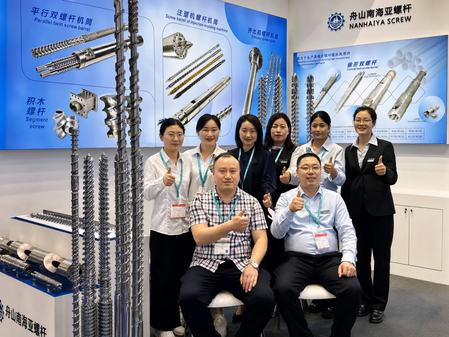
Related Articles
More insights on screw barrel technology and plastics processing.
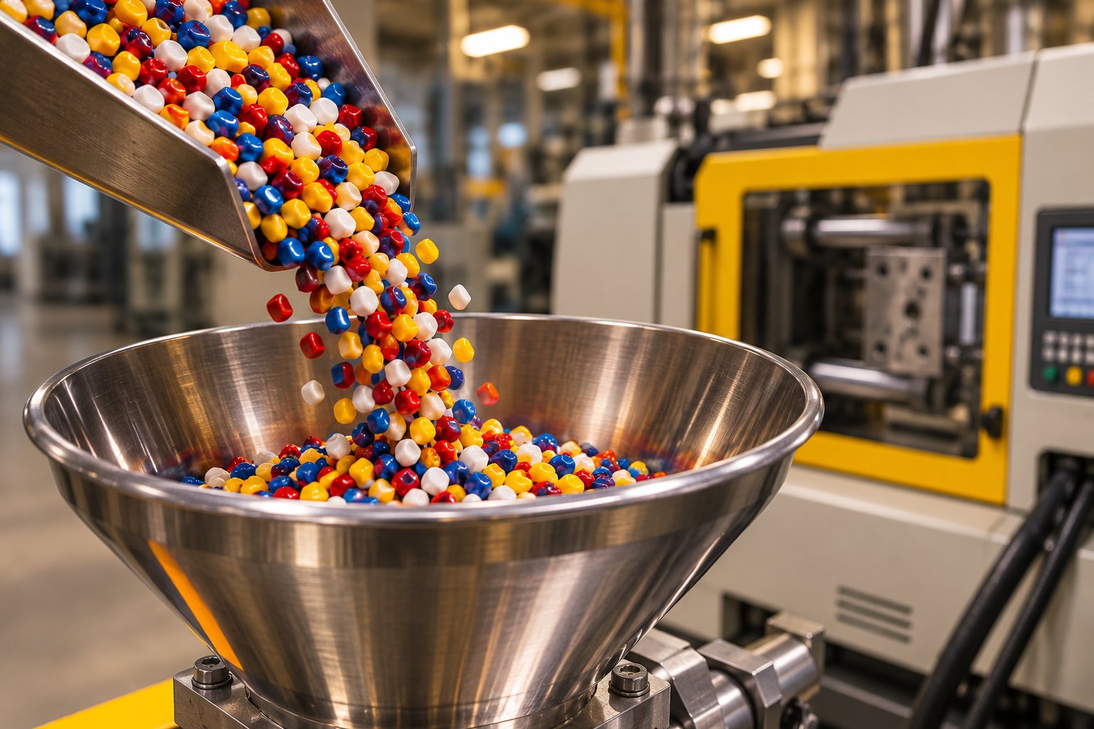
Injection Molding Color Mixing: From Streaks to Flawless Consistency
Nov 19, 2026
Master injection molding color mixing with expert guidance on colorant types, screw design, process parameters, defect troubleshooting, and Delta E QC protocols.
Read Article
Wrong Extruder Breaker Plate? Spot the Signs Before Scrap Piles Up
Nov 19, 2026
Learn how to select, size, and maintain your extruder breaker plate. Covers hole geometry, pressure drop, polymer-specific specs, and troubleshooting tips.
Read Article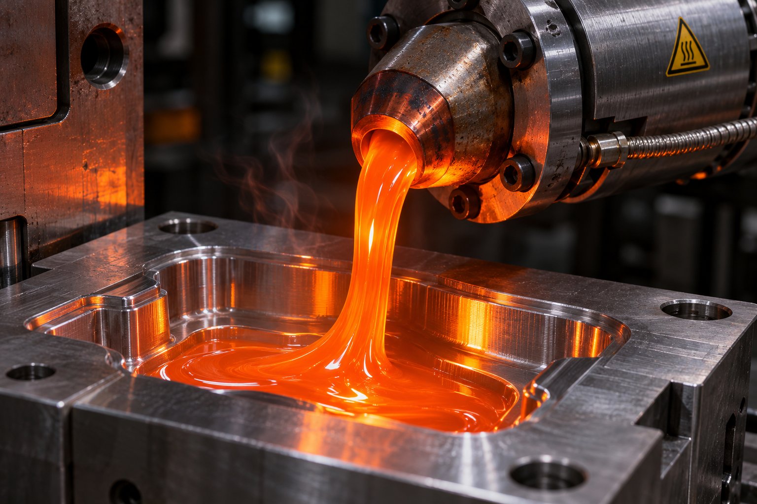
Injection Molding Melt Temperature: Why Your Barrel Settings Lie
Nov 19, 2026
Learn why barrel set points lie about injection molding melt temperature. Complete resin chart, measurement methods, defect troubleshooting, and optimization steps.
Read ArticleLooking for something else?
Search by material, symptom or product and jump straight to the relevant page.
These are navigation suggestions based on keyword matching — not a quotation, not a delivery commitment, and not a substitute for engineering review. Final specification is confirmed by our engineers against your drawings and processed material.
Need help with screw barrel selection?
Share your machine model, processed material and application. Our team can help with pricing and technical support.