

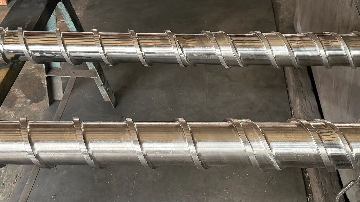
What Is Screw Compression Ratio and Why Every Processor Should Understand It
Imagine feeding solid plastic pellets into one end of a machine and expecting a perfectly uniform, bubble-free melt to exit the other. What determines how aggressively those pellets are squeezed, heated, and blended along the way? The answer comes down to a single dimensionless number: the screw compression ratio.
Screw compression ratio is the ratio of the feed-zone channel depth to the metering-zone channel depth on an extrusion or injection molding screw. It quantifies how much the available volume for polymer decreases as material travels from hopper to die or nozzle.
This ratio, often expressed in the format 3:1 or 2.5:1, acts as the master lever behind plasticating performance. A higher value means the screw compresses material more aggressively, generating greater shear heat and tighter melt consolidation. A lower value applies gentler compression, which suits polymers that degrade under excessive mechanical energy. Getting it right influences melt quality, throughput stability, energy consumption, and final part consistency - whether you are running a blown-film line or molding precision connectors.
Core Definition and Why It Matters
The extrusion screw compression ratio is not just a feeding parameter. As Paul Murphy Plastics highlights, it must be established not only to convey enough solid polymer to fill the screw but also to introduce sufficient shear heating to complete melting. Every polymer demands a different energy input per unit of output, so the ratio directly shapes how much mechanical work the screw performs on the resin. The compression ratio injection molding screw designers specify follows the same principle: a higher ratio drives more friction, more uniform heat distribution, and potentially more stress in sensitive resins. A ratio that is too low leaves unmelted particles in the output, while one that is too high can scorch heat-sensitive materials or spike motor load unnecessarily.
Screw Compression Ratio vs. Screw Compressor Compression Ratio
A common point of confusion deserves a quick clarification. The compression ratio of a screw compressor - the kind used in refrigeration, HVAC, and compressed-air systems - refers to the pressure ratio between discharge and suction ports of a rotary screw gas compressor. It has nothing to do with polymer processing. Screw compressors deal with gas volume reduction; plasticating screws deal with channel-depth reduction along a solid-to-melt transition. If you landed here looking for refrigeration compressor data, you'll want a different resource. For everyone focused on plastics processing, this article walks you through the formula, polymer-specific selection guidelines, extrusion versus injection molding differences, and a troubleshooting framework that connects theory directly to floor-ready results.
The logical starting point is the screw itself - specifically, the three functional zones whose geometry creates the compression ratio in the first place.
How Screw Zones and Channel Depth Determine Compression Ratio
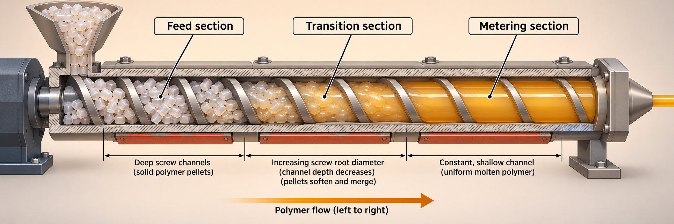
Picture a standard single-screw extruder or injection molding screw laid out on a bench. From the shank end to the tip, you'll notice the root diameter gradually increases - meaning the spiral channel carved between the flights gets progressively shallower. That physical taper is not decorative. It is the engine behind the extruder screw compression ratio, and understanding its three distinct zones is the key to grasping why this number matters so much on the processing floor.
A standard plasticating screw divides its working length into three functional zones: feed, transition (also called compression), and metering. Each zone has a specific channel depth profile and a distinct job. The table below maps out how they relate.
| Zone | Typical Share of Screw Length | Channel Depth Trend | Primary Function |
|---|---|---|---|
| Feed | ~50% (varies by design) | Constant and deepest | Accept and convey solid pellets or powder |
| Transition (Compression) | ~25% | Progressively decreasing | Compress solids, expel trapped air, initiate melting |
| Metering | ~25% | Constant and shallowest | Homogenize melt, generate stable pumping pressure |
Zone proportions are approximate and shift depending on the polymer and application. Some screw designs allocate a longer feed zone; others extend the metering section for better mixing. What stays universal is the relationship between the deepest channel in the feed zone and the shallowest channel in the metering zone - that ratio is the geometric compression ratio.
Feed Zone — Solids Conveying and Maximum Channel Depth
When pellets tumble from the hopper into the barrel, they land in the feed zone. Here, the channel between flights is at its maximum depth, creating plenty of room to accept irregularly shaped granules, powder, or flake. The screw's rotation drags these solids forward through friction against the barrel wall. Think of it like a conveyor belt wrapped in a spiral: the deeper the channel, the more material each flight can carry per revolution.
As veteran extrusion engineer Allan Griff explains, the feed zone depth must be "deep enough to take in the plastic particles," and it remains constant throughout this section. At this stage, the polymer is still entirely solid, and the zone's job is simply to move as much of it forward as possible without jamming or starving the downstream sections.
Transition Zone — Where Compression and Melting Occur
This is where the action intensifies. As material advances into the transition zone, the channel depth begins to decrease - "as if the walls were closing in on the plastic," in Griff's words. That shrinking volume does two critical things simultaneously. First, it squeezes out the air trapped between pellets, preventing bubbles from contaminating the melt downstream. Second, it forces pellets into tighter contact with one another and with the heated barrel wall, generating frictional and conducted heat that starts the melting process.
You'll sometimes hear this section called the compression zone, and the name is fitting. The rate at which channel depth decreases - gradual or aggressive - directly controls how quickly the polymer transitions from a loose bed of solids to a pressurized, partially molten mass. A steep taper compresses material rapidly and suits polymers that melt over a narrow temperature range. A gentle taper spreads the compression over more screw length, which benefits heat-sensitive resins that degrade under sudden shear spikes.
Metering Zone — Melt Pumping at Minimum Channel Depth
By the time material reaches the metering zone, it should be nearly all melted. This zone has a constant - and much shallower - channel depth. Its job is to homogenize the melt to a uniform temperature and viscosity, then pump it forward at a steady rate against the resistance of the die, screen pack, or nozzle.
Because the channel is shallow, even small dimensional changes here have outsized effects. A metering depth of 2.5 mm versus 3.0 mm, for example, doesn't sound dramatic - yet it shifts the compression ratio of the extruder screw by roughly half a point, enough to alter shear rates, melt temperature, and output stability in measurable ways.
It's worth noting that the geometric depth ratio between feed and metering zones is not the only factor influencing effective volumetric compression. Flight width, helix angle, and the number of flights all play supporting roles. Wider flights reduce the open channel area per turn, and a non-standard helix angle changes how material is dragged forward. These variables are secondary to channel depth but important enough that two screws with identical depth ratios can behave differently if their flight geometry diverges.
With the three zones mapped and their channel-depth relationships clear, the natural next step is turning those physical dimensions into a number you can calculate, compare, and optimize - the extruder screw compression ratio calculation itself.
Step-by-Step Screw Compression Ratio Calculation With Worked Examples
You know the three zones, you understand that channel depth decreases from feed to metering - but how do you turn those physical dimensions into a usable number? The screw compression ratio formula is refreshingly simple, yet the details around measuring and interpreting it trip up even experienced processors. Let's break it down.
The Compression Ratio Formula Explained
The calculation requires only two measurements:
CR = Feed Channel Depth (Hf) ÷ Metering Channel Depth (Hm)
That's it. Divide the deepest channel section by the shallowest, and you get a dimensionless ratio typically written in the format X:1. A result of 3.0, for instance, means the feed channel holds three times the volume per unit length compared to the metering channel.
One important nuance: this standard screw compression ratio formula assumes the lead length (also called pitch) stays the same in both the feed and metering sections. If the helix angle or the number of flights changes between zones, a simple depth ratio alone won't capture the full volumetric picture - but for the vast majority of conventional three-zone screws, the depth-based formula is the industry-accepted standard.
Channel depth itself is measured from the screw root (the bottom of the channel) to the inner barrel wall, minus the small radial clearance between the flight land and the barrel bore. In practice, most engineers measure directly from root to flight tip on the screw itself, since the flight outside diameter approximates the barrel bore on a new or well-maintained system.
Worked Calculation Examples for Extrusion and Injection Molding
Example 1 — General-Purpose Polyolefin Extrusion Screw
Imagine a 90 mm single-screw extruder designed for HDPE blown film. After pulling the screw, you measure:
- Feed channel depth (Hf): 8.0 mm
- Metering channel depth (Hm): 2.5 mm
CR = 8.0 ÷ 2.5 = 3.2:1
This falls squarely within the typical range for semi-crystalline polyolefins, which need firm compression to accommodate the significant density change between solid pellet and melt.
Example 2 — Injection Molding Screw for ABS
Consider a 50 mm reciprocating screw on a mid-tonnage injection molding machine processing ABS, an amorphous resin with a gradual softening transition:
- Feed channel depth (Hf): 6.0 mm
- Metering channel depth (Hm): 2.8 mm
CR = 6.0 ÷ 2.8 = 2.14:1
The lower injection molding screw compression ratio reflects two realities: amorphous polymers undergo less density change during melting, and the reciprocating screw process offers additional melt-quality controls - like backpressure and screw-back speed - that continuous extrusion lacks.
Real-World Data Point — Dow Inc. Research
A published study by Dow Inc. researchers Lin Jin and Mark Spalding tested five screws on a highly instrumented 2.5-inch (63.5 mm) extruder processing LLDPE. All five screws shared an identical metering channel depth of 0.125 inch (3.175 mm), while feed depths varied to produce compression ratios of 2.0, 2.4, 2.8, 3.2, and 3.6. The study found that screws near a 2.8:1 ratio delivered the best balance of throughput, melt quality, and pressure stability for LLDPE pellet feedstocks. Ratios below 2.4 could not maintain full channel pressure in the metering zone at low screw speeds, while ratios above 2.8 increased discharge temperatures by 5-10 degrees C and drove higher flight wear rates at the end of the transition section. These results underscore that even modest shifts in the ratio - just a few tenths of a point - produce measurable performance differences on real production equipment.
How to Measure Channel Depth on an Existing Screw
Sounds straightforward on paper, but measuring channel depth on a screw you've pulled from a barrel requires a methodical approach to avoid common errors. Here is the step-by-step procedure:
- Clean the screw thoroughly. Remove all residual polymer from the channels, especially in the metering zone where thin melt films can mask the true root diameter. A brass brush or a heat gun helps loosen stubborn residue without scratching hardened surfaces.
- Support the screw horizontally. Place the screw on V-blocks or a screw rack so it doesn't roll and you can access channel sections consistently.
- Identify the feed and metering zones. Locate the region of constant deep channel (feed) and the region of constant shallow channel (metering). Avoid measuring in the transition zone, where depth changes along each turn.
- Measure the flight outside diameter (OD). Using a micrometer or large-jaw calipers, measure across the flight tips at several points in both the feed and metering zones. Record the average. On a worn screw, you may notice the OD is smaller near the metering end - that wear matters and will be discussed later in this article.
- Measure the root diameter. Place a depth gauge or vernier caliper from the flight tip down to the root surface at the center of the channel. Repeat at three or four flight turns within each zone and average the readings.
- Calculate channel depth. Channel depth = (Flight OD - Root Diameter) ÷ 2. Perform this for both the feed zone and the metering zone.
- Compute the compression ratio. Divide the average feed channel depth by the average metering channel depth.
Keep in mind that published compression ratios assume nominal, as-manufactured dimensions. Barrel bore wear, flight land erosion, and normal manufacturing tolerances can shift the effective ratio away from the number printed on a spec sheet. Always verify with physical measurements when diagnosing process issues.
With a confirmed ratio in hand, the next question naturally arises: what number should you actually be targeting? The answer depends heavily on the polymer you are processing - specifically, whether it is semi-crystalline or amorphous - and how it behaves during the solid-to-melt transition.
Compression Ratio Selection by Polymer Type and Morphology
The formula is universal, but the number you plug in is not. A compression ratio extrusion screw that works beautifully for HDPE can wreak havoc on polycarbonate, and a gentle ratio that protects PVC from degradation would starve a nylon line of the compaction energy it needs. The deciding factor? How a polymer's molecular structure behaves during the solid-to-melt transition - and that behavior splits along one fundamental dividing line: semi-crystalline versus amorphous morphology.
Why Semi-Crystalline Polymers Need Higher Compression Ratios
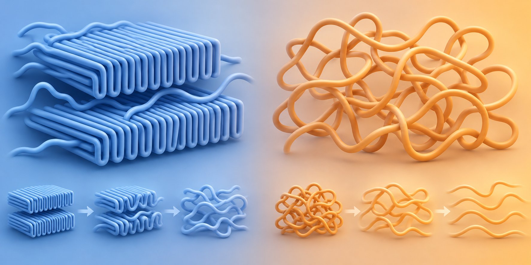
Semi-crystalline polymers like PE, PP, PA (nylon), and PET contain regions where molecular chains pack into tightly ordered crystalline structures. When these regions melt, the orderly packing collapses into a denser, disordered liquid. That collapse produces a sharp, well-defined melting point and - critically - a large drop in specific volume over a narrow temperature range.
Consider HDPE. As polymer engineering references note, semi-crystalline polymers have closely defined melting temperatures, and HDPE crystallinity levels often exceed 60%. Solid HDPE pellets enter the feed zone with a bulk density around 590 kg/m³ and melt to roughly 760 kg/m³. That roughly 29% densification means the metering zone must handle a significantly smaller volume of material than what the feed zone originally accepted. Without enough geometric compression to match this density swing, the metering channel runs partially empty - output drops, pressure fluctuates, and melt quality deteriorates.
Amorphous polymers tell a completely different story. Materials like PS, ABS, PC, and PMMA lack long-range crystalline order. Their molecular chains are arranged randomly - often compared to cooked spaghetti - so they don't undergo a dramatic structural collapse upon heating. Instead, they soften gradually through a glass transition temperature range, with a far smaller change in density from solid to melt. The screw simply doesn't need to squeeze as hard to keep the metering zone full and pressurized, which is why ratios between 1.5:1 and 3.0:1 typically suffice.
Recommended Compression Ratios by Polymer Family
When calculating compression ratio of a screw barrel setup for a specific resin, the table below gives you a practical starting range. These values reflect widely accepted industry practice for standard pellet feedstocks processed on conventional three-zone screws. Note that actual requirements shift with specific resin grades, filler content, and production targets - treat these as calibrated first guesses, not final specifications.
| Polymer Family | Morphology | Recommended CR Range | Processing Notes |
|---|---|---|---|
| LDPE / LLDPE | Semi-crystalline | 2.8:1 - 4.0:1 | Broad processing window; LLDPE often optimal near 2.8:1 per Dow research. Higher ratios tolerated due to low viscosity. |
| HDPE | Semi-crystalline | 3.0:1 - 4.5:1 | High crystallinity demands aggressive compaction. Grooved feed barrels may allow slightly lower geometric ratios. |
| PP | Semi-crystalline | 2.5:1 - 3.5:1 | Lower melt viscosity than HDPE permits moderate ratios. Copolymer grades lean toward the lower end. |
| PA6 / PA66 (Nylon) | Semi-crystalline | 3.5:1 - 4.5:1 | Very high crystallinity and sharp melt transition. Requires thorough drying. Highest ratios in commodity processing. |
| PET | Semi-crystalline | 2.5:1 - 3.5:1 | Moisture-sensitive; excess shear raises acetaldehyde generation in packaging grades. |
| PS (GPPS / HIPS) | Amorphous | 2.0:1 - 3.0:1 | Small bulk-to-melt density gap. PS plasticates best at 3.0:1 per Dow case studies; HIPS is similar. |
| ABS | Amorphous | 2.0:1 - 2.5:1 | Rubber phase is shear-sensitive; over-compression degrades impact properties. 2.5:1 is a proven commercial value. |
| PC | Amorphous | 2.0:1 - 2.8:1 | High melt viscosity generates significant shear heat at elevated ratios; protect optical clarity with gentle compression. |
| PMMA | Amorphous | 2.0:1 - 3.0:1 | Sensitive to moisture-induced splay and thermal yellowing. Moderate compression avoids both. |
| PVC (rigid) | Amorphous | 1.5:1 - 2.5:1 | Narrow thermal window; aggressive compression triggers dehydrochlorination. Powder feedstock demands carefully matched feed depth. |
| PVC (flexible) | Amorphous | 2.5:1 - 3.5:1 | Plasticizer lowers viscosity, permitting somewhat higher ratios, but thermal degradation limits still apply. |
A quick clarification for anyone who arrived here searching for the screw compressor compression ratio used in refrigeration or HVAC: the values above apply exclusively to plasticating screws in polymer processing. A compression ratio for a screw compressor describes a gas pressure ratio between suction and discharge ports - an entirely different concept with different engineering rules.
Special Considerations for Heat-Sensitive Resins and Recycled Materials
Some polymers simply cannot tolerate the mechanical energy that higher ratios generate, regardless of what their density profile might suggest. PVC is the textbook case. Its processing window typically spans just 160 °C to 200 °C, and exceeding those limits triggers rapid chemical degradation. Every extra point of compression ratio translates into steeper velocity gradients across the channel, higher shear rates, and more viscous dissipation converting drive energy into heat the barrel cooling system may not be able to remove fast enough. That is why rigid PVC screws stay at 1.5:1 to 2.5:1 - values that seem low next to polyolefins but are essential for thermal survival.
PVDF and certain biopolymers like PHA face similar constraints. PHA's decomposition temperature sits dangerously close to its melting point, demanding melt temperatures below 185 °C and the gentlest compression profiles available. For any heat-sensitive resin, the rule is the same: design the screw to compress only as much as the polymer's thermal budget allows, even if solids-conveying efficiency takes a small hit.
Recycled resins and regrind introduce a challenge that most compression ratio guides overlook entirely. Post-consumer or post-industrial regrind arrives with bulk densities that are lower and far more variable than virgin pellets. Irregular flake geometry traps air, bridges in the feed throat, and packs unpredictably from batch to batch. The practical consequence is straightforward: the same geometric ratio that keeps a metering zone full and pressurized with virgin pellets often leaves it partially starved when processing regrind.
Recycled PE or PP in re-pelletized form typically needs ratios in the 3.0:1 to 4.0:1 range - roughly matching virgin values because the re-pelletizing step restores a consistent bulk density. Recycled flake or coarse regrind, however, can demand ratios of 3.5:1 to 5.0:1 to compensate for poor packing. Mixed recycled polymer streams are even more unpredictable; no single published ratio applies, and processors should determine feeding requirements from actual bulk density measurements of each incoming batch rather than relying on a chart.
Contamination adds another layer. Residual labels, adhesives, or mixed-polymer inclusions alter melt viscosity in ways that shift the effective compression the screw delivers. A batch of recycled HDPE bottles contaminated with PP caps behaves differently from a clean HDPE stream, even at the same geometric ratio. For operations running significant regrind percentages, periodic bulk density checks and melt quality audits are the only reliable way to confirm the screw's compression geometry still matches the feedstock.
These polymer-specific guidelines provide a solid foundation for ratio selection - but they assume you are choosing a screw for one process type. In reality, many processors work across both extrusion and injection molding, and the same ratio range does not carry over directly between the two. The differences in how each machine uses its screw change the compression equation in ways that deserve their own closer look.
Extrusion vs Injection Molding — How Compression Ratio Requirements Differ
A 3.2:1 compression ratio of screw geometry performs one way when the screw never stops turning. It behaves quite differently when that same screw rotates, retracts, pauses, and then rams forward as a piston. The mechanical motion of the process changes how compression energy is applied to the polymer - and that changes which ratio actually delivers the best results. Yet most published guides treat extrusion and injection molding screws as interchangeable when discussing compression ratios. They are not.
Continuous Extrusion and Steady-State Compression Demands
In extrusion, the screw rotates continuously in one direction inside the barrel. Material flows from hopper to die in a steady stream, and the compression ratio directly controls how aggressively solids are compacted, melted, and pressurized along the way. There are no pauses, no stroke-by-stroke cycles, and no plunger action. The screw is the sole mechanism responsible for generating the head pressure needed to push melt through a die.
This places heavy demands on the compression geometry. If the ratio is too low, the metering zone runs partially empty, output surges, and die pressure fluctuates. If it is too high, excessive shear heat drives up melt temperature beyond what barrel cooling can manage. In either case, the problem is persistent because the process never resets - every revolution compounds the error. That is why extrusion screws for semi-crystalline polymers often run at the higher end of their recommended range (3.0:1 to 4.5:1), and why extrusion screws are designed to generate high pressures and maintain consistent material flow over extended production runs.
Reciprocating Injection Molding Screws and Backpressure Dynamics
Injection molding rewrites the rules. Here, the screw performs two fundamentally different jobs within each cycle. During the plasticizing (recovery) phase, it rotates inside the barrel to melt and meter material into a shot in front of the screw tip - much like a miniature extruder. Then rotation stops, and the entire screw pushes forward as a plunger to inject that accumulated shot into the mold cavity.
This reciprocating motion means the screw compression ratio only governs melt quality during the recovery phase. During injection and hold, the screw is a ram - compression geometry is irrelevant. More importantly, injection molding machines offer an additional control that continuous extrusion does not: backpressure. Increasing backpressure during screw retraction forces the screw to work harder to push material forward, effectively boosting melt homogeneity and compaction without changing the physical screw geometry at all. Screw-back speed provides yet another lever, controlling how long the polymer spends in the transition zone per revolution.
These extra process variables explain why recommended injection molding screw designs typically call for a compression ratio between 2:1 and 3:1 with L/D ratios of 18:1 to 24:1. The screw does not need to carry the full burden of melt quality alone - backpressure and recovery speed share the load.
Residence time creates another important distinction. Injection molding cycles include cooling time, mold opening, part ejection, and sometimes extended dwell periods during color changes or downtime. Polymer sitting in a barrel with an aggressively high compression ratio keeps absorbing shear and conducted heat even when the screw is idle. For heat-sensitive resins like PVC or PET, this extended residence under compression can trigger degradation, discoloration, or off-gassing that would never appear in a continuously moving extrusion process where material flushes through in seconds.
Practical Implications When Switching Between Processes
The comparison below highlights the key differences a processor should evaluate when selecting or reviewing compression ratio for either platform.
| Dimension | Continuous Extrusion | Reciprocating Injection Molding |
|---|---|---|
| Screw Motion | Continuous rotation in one direction | Rotate-retract during recovery, then linear plunger stroke during injection |
| Typical CR Range | 2.5:1 - 4.5:1 (polymer-dependent) | 2.0:1 - 3.0:1 (moderate by design) |
| Pressure Generation | Screw geometry and rotation are the sole source of head pressure | Screw geometry generates backpressure during recovery; hydraulic or servo system generates injection pressure |
| Additional Melt Quality Controls | Limited — primarily barrel temperature profile and screw speed | Backpressure, screw-back speed, injection speed, and hold pressure all contribute |
| Residence Time | Short and consistent (continuous flow) | Variable and often longer (cycle pauses, idle periods) |
| Key Quality Concern | Output stability and melt uniformity over hours of continuous operation | Shot-to-shot consistency, degradation during idle time, and shear sensitivity during injection |
Why does this matter on the shop floor? Imagine a processor running PP on an extrusion line at 3.0:1 and then using a similar ratio on an injection molding machine for the same resin. In extrusion, that ratio delivers solid melt quality at steady state. In injection molding, the same 3.0:1 may generate unnecessary shear heat during recovery - heat that keeps building during the cooling portion of the cycle when no fresh material flushes through the barrel. Dropping to 2.5:1 on the molding screw while increasing backpressure slightly often achieves equivalent melt homogeneity with lower peak melt temperatures and tighter shot-weight control.
The reverse scenario is equally problematic. Specifying a gentle 2.0:1 ratio because it works well on an injection molding machine, then installing a similar screw on an extruder running the same resin, risks chronic undercompression. Without backpressure to compensate, the metering zone starves, output surges, and unmelted particles survive to the die.
The takeaway is direct: never assume a compression ratio transfers one-to-one between extrusion and injection molding, even for the same polymer. The process mechanics redefine what "enough compression" means.
Of course, both extrusion and injection molding have moved well beyond simple three-zone screws. Barrier flights, specialized mixing elements, and grooved feed barrels all modify how compression actually behaves inside the barrel - sometimes making the geometric ratio on a spec sheet only part of the story.
Beyond Three-Zone Screws — Barrier Flights, Mixing Elements, and Effective Compression Ratio
A standard three-zone screw is a reliable workhorse, but it is also a design from the mid-twentieth century. Modern processing demands - tighter melt temperature tolerances, higher throughput targets, thinner gauge tolerances, and the growing use of recycled feedstocks - have pushed screw technology well past the simple feed-transition-metering architecture. Barrier screws, dispersive and distributive mixing sections, and grooved-feed barrels all reshape how compression energy reaches the polymer. And here is the catch: they can make the geometric screw compression ratio printed on a spec sheet only a partial description of what is actually happening inside the barrel.
Barrier Screws and Their Impact on Compression Behavior
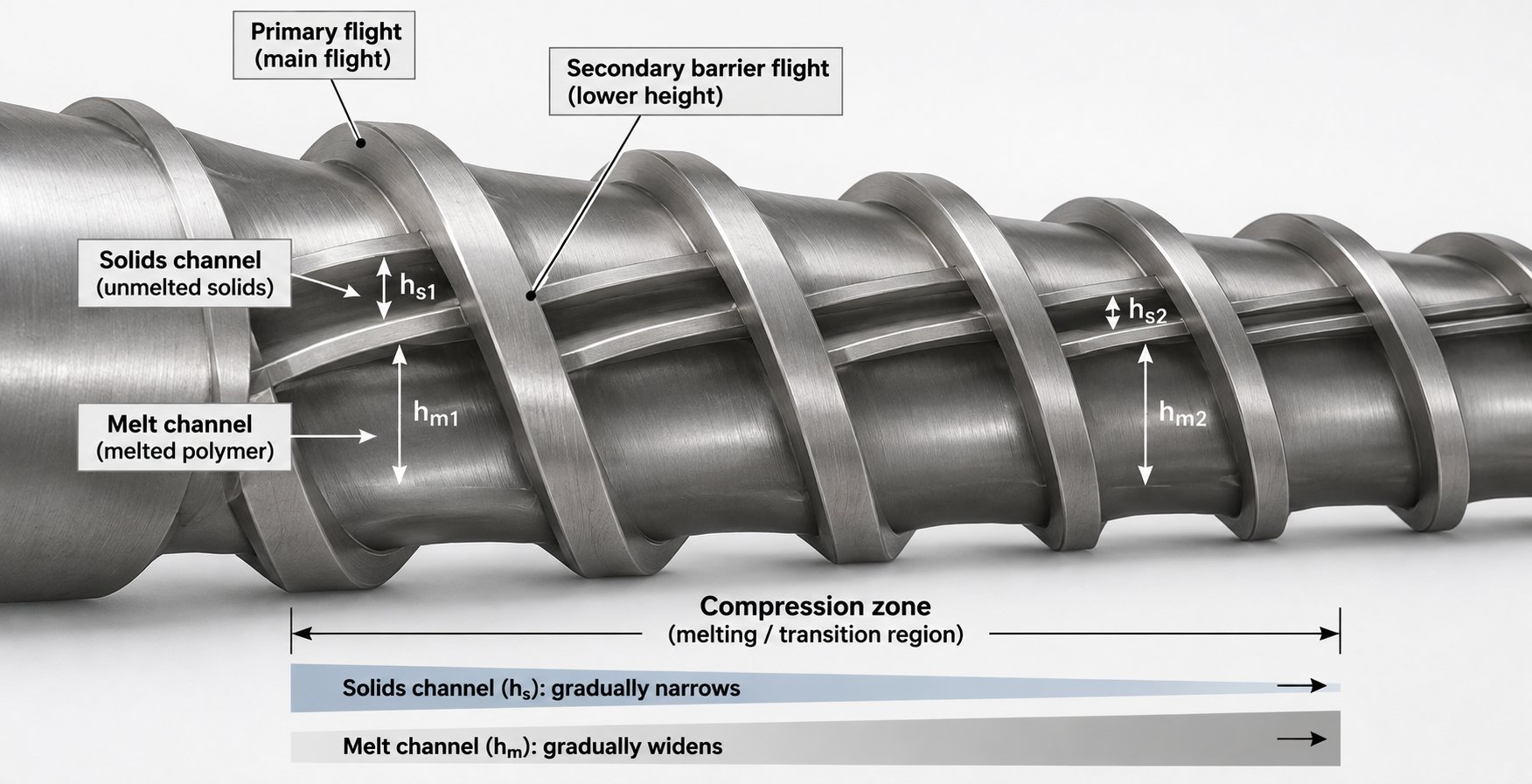
Imagine a second, thinner flight spiraling alongside the main flight through most of the compression zone. That secondary flight - called the barrier flight - divides the channel into two parallel paths: one dedicated to unmelted solids, the other to collecting melt. The clearance between the barrier flight and the barrel wall is wide enough to let molten polymer flow over (typically around 0.50 to 0.75 mm), but narrow enough to block solid pellets, which are roughly 1.5 mm or larger.
As Allan Griff describes, the pellets stay in their main channel but are "drained of excess melt and, thus, generate more frictional heat as they rub against one another." The result is faster, more efficient melting per screw revolution. As material advances, the melt channel grows in volume while the solids channel shrinks, until the solids are fully consumed and a single flight carries the homogeneous melt into the metering zone.
Why does this matter for screw compression ratio calculation? Because a barrier screw fundamentally changes the compression profile even if its feed and metering channel depths yield the same geometric ratio as a conventional three-zone design. The solid bed never breaks up chaotically the way it can in a simple transition zone. Instead, it is continuously drained and compacted in a controlled path. The effective compression the polymer experiences - the actual pressure, shear, and volumetric reduction at each point along the screw - diverges significantly from what a simple depth ratio would predict. Two screws with identical 3.0:1 geometric ratios, one conventional and one barrier, will deliver meaningfully different melt temperatures, mixing quality, and throughput ceilings.
Research reinforces this distinction. A 2026 study published in Applied Sciences tested a BARR barrier screw in combination with grooved barrel configurations and found that the barrier flight's liquid-phase channel blocks unmolten material migration, creating a local high-pressure zone that stabilizes the melting start point - an effect entirely invisible in the geometric ratio. Barrier screws designed for grooved barrel extruders have been shown to achieve high performance across a broad range of resins, precisely because they decouple the melting behavior from the simple depth-ratio arithmetic.
Geometric vs Effective Compression Ratio
This brings us to a distinction every processor should internalize: the geometric compression ratio and the effective compression ratio are not the same number.
The geometric ratio is exactly what earlier chapters calculated - feed channel depth divided by metering channel depth, measured on the screw with calipers. It is a fixed property of the screw's machined dimensions. The effective ratio, by contrast, describes the actual volumetric compression the polymer experiences as it travels through the system. Several real-world factors push these two numbers apart:
- Flight clearance and barrel wear. New screws have a flight-to-barrel clearance of roughly 0.125 to 0.25 mm, but wear widens this gap over time. Increased clearance in the metering zone allows more backward leakage flow (melt slipping past the flight land), reducing effective compression even though the root dimensions have not changed.
- Melt density changes. Semi-crystalline polymers undergo a substantial density increase upon melting. The metering channel must accommodate a denser fluid than the loose solid bed the feed zone accepted. If the geometric ratio does not account for this density swing, the metering zone may be overfull or underfull compared to expectations.
- Barrier flight geometry. As discussed above, a secondary barrier flight redirects melt away from the solid bed, creating two independent compression profiles within what appears to be a single screw section. The screw compression ratio calculation based on overall channel depth misses this internal segregation entirely.
- Mixing sections. Devices like Maddock mixers, Saxton mixers, or cavity transfer mixers impose additional shear and pressure drops within the metering zone. A Maddock section - a roughly two-diameter-long segment with paired flutes separated by a barrier ridge - forces melt through a tight clearance of about 0.50 to 0.75 mm. Unmelted fragments cannot pass whole; they are sheared and flattened until they pass as melt. This adds an effective compression and filtration step that the geometric ratio never captures.
- Non-standard flight geometry. Double-flighted zones, variable-pitch (non-square) leads, or wave-screw designs alter the volumetric flow path. In a wave screw, for instance, the two or three parallel channels have depths that rise and fall out of phase, forcing melt back and forth across a low barrier - excellent for mixing, but impossible to describe with a single depth ratio.
- Feed throat conditions. Water-cooled feed throats or textured barrel liners in the feed zone change how efficiently solids enter the channel, effectively increasing or decreasing the functional feed depth beyond what a caliper reads on the screw root.
The practical implication? When you measure a screw and calculate a ratio of, say, 2.8:1, that number tells you the starting geometry. It does not tell you how the screw actually compresses your specific polymer under your operating conditions. Two processors running the same geometric ratio on identical screws can get different outcomes simply because one has a worn barrel, a different mixing section downstream, or a grooved feed section that changes solids intake behavior. Treating the geometric ratio as the final word on compression performance leads to misdiagnosis when problems arise.
Grooved Feed Sections and Compression Ratio Interaction
Grooved feed barrels illustrate this geometric-versus-effective gap more dramatically than any other single hardware change. In a conventional smooth-bore barrel, solids conveying depends on friction between the pellets and the barrel wall exceeding friction between pellets and the screw root. That is why processors sometimes chrome-plate the screw root to reduce grip while keeping the barrel surface rough.
A grooved feed section takes a completely different approach. Axial or helical grooves machined into a water-cooled barrel liner in the feed zone physically lock pellets against the barrel wall, converting material transport from friction-drag conveying to near-positive-displacement conveying. The throughput increase is dramatic - solids conveying efficiency can jump 30% or more compared to a smooth bore.
Here is where the injection screw compression ratio mindset needs to shift. With a grooved feed barrel pushing far more solid polymer downstream per revolution, the screw's transition and metering zones receive material faster than a smooth bore would deliver it. If the screw's geometric ratio was designed around smooth-bore feeding rates, the metering zone can become overpressured and melt temperature spikes. The standard remedy, as Griff notes, is "a screw with a shallower feed and deeper metering zone" - sometimes with no compression at all in the traditional sense. The grooved barrel effectively takes over the compression function, allowing the screw geometry to focus on mixing and pumping instead.
The tradeoff is mixing quality. A deeper metering channel pumps well but generates less shear, which can leave the melt poorly homogenized. That is why grooved-feed systems almost always pair with an intensive mixing section at the screw's output end or a static mixer in the die adapter. Experimental work on grooved barrel single-screw extruders demonstrates this synergy: when barrel grooves extend into the melting zone and the screw uses a barrier design, the melting start point can shift 24% earlier than conventional IKV grooved configurations, and the melting length shrinks to roughly 63% of the reference value. The actual throughput in such systems reaches 93-96% of the theoretical solid conveying capacity - a level impossible with smooth-bore barrels at comparable geometric ratios.
For processors evaluating PVC extrusion screw compression ratio requirements, the grooved-feed interaction is especially relevant. PVC's narrow thermal window makes high geometric ratios risky, yet output targets still demand efficient solids conveying. A grooved feed section paired with a low-compression or even zero-compression screw can deliver both thermal safety and high throughput - a combination the geometric ratio alone would never suggest is possible.
All of these advanced screw technologies share a common thread: they make compression behavior more complex and more capable, but also harder to diagnose when something goes wrong. When melt quality deteriorates, output fluctuates, or reject rates climb, knowing whether the root cause is an inadequate geometric ratio, a worn barrier flight, or a mismatched grooved-feed interaction requires a structured troubleshooting approach - one that connects visible symptoms back to their compression-related origins.
Troubleshooting Processing Problems Linked to Compression Ratio
You have measured the screw, calculated the ratio, confirmed the polymer's recommended range, and accounted for barrier flights or grooved-feed interactions. Production starts - and something still goes wrong. Output surges. Melt temperatures climb past spec. Color streaks refuse to disappear. The instinct is to chase barrel temperatures or tweak screw speed, but the root cause may be hiding in plain sight: a mismatch between the compression geometry and the material's actual behavior inside the channel.
What follows is a structured troubleshooting framework that connects visible floor-level symptoms to their compression-ratio origins - and, just as importantly, tells you what to do about them.
Symptoms of Insufficient Compression Ratio
When the ratio is too low for the polymer being processed, the screw simply cannot compact the solid bed tightly enough. Air stays trapped between pellets, the metering zone runs partially starved, and the melt leaving the screw tip is neither uniform nor pressurized consistently. Two classic failure modes result.
Output surging and pressure fluctuations. Imagine watching your die pressure gauge: instead of a steady reading, the needle oscillates in a rhythmic cycle - sometimes as slow as every 30 to 60 seconds. This happens because the solid bed in the transition zone never fully consolidates. Pockets of loosely packed pellets advance unevenly into the metering section, where they momentarily reduce melt volume and pressure before the next slug of compacted material arrives. The downstream effect is visible as periodic thickness variations in sheet, blown film, or pipe wall. Extrusion troubleshooting guides identify output surging as typically stemming from inconsistent feeding, contaminated material, or incorrect screw speed - but a compression ratio that is simply too low for the resin's bulk-to-melt density gap is often the underlying geometric cause that no process adjustment can fully override.
Unmelted particles and gels. If you are finding translucent specks, hard inclusions, or gel-like lumps in your extrudate or molded parts, the screw may not be generating enough shear and compaction to break down the last pockets of unmelted polymer. A too-low ratio leaves the solid bed undercompressed in the transition zone, allowing unmixed regions to survive all the way to the die. For semi-crystalline polymers like HDPE or nylon - which undergo a sharp melt transition and rely heavily on frictional heat from compaction - even a half-point deficit in the ratio can leave visible unmelt in the product.
Symptoms of Excessive Compression Ratio
Overcompression creates the opposite set of problems, and they can be just as damaging - sometimes more so, because the consequences include chemical degradation that permanently destroys the polymer.
Excessive melt temperature and thermal degradation. Every extra increment of compression forces the polymer through steeper velocity gradients across a shallower channel, and those gradients convert motor energy into heat through viscous dissipation. When the ratio overshoots what the polymer needs, melt temperature can climb 10 to 20 degrees C above the target - well into degradation territory for heat-sensitive resins. For PET packaging grades, this means elevated acetaldehyde levels. For soft PVC injection molding applications, aggressive compression triggers dehydrochlorination, releasing hydrochloric acid that corrodes tooling and contaminates parts. The screw compression ratio for soft PVC injection molding must stay low enough - typically 2.0:1 to 2.5:1 - precisely because the thermal penalty of overcompression is irreversible.
Similarly, the screw compression ratio for PET needs careful calibration. PET's moisture sensitivity compounds the problem: any excess shear heat accelerates hydrolytic degradation if residual moisture is present, producing haze, brittleness, and off-flavors in food-contact applications. Processors running PET at ratios above 3.5:1 on standard screws frequently report yellowing and intrinsic viscosity loss - both indicators that the polymer is being mechanically overworked.
High motor load and wasted energy. An oversized ratio forces the drive system to push harder against elevated channel pressures. You'll see this as a creeping increase in motor amperage at constant screw speed, or as the screw speed ceiling dropping because the drive reaches its torque limit sooner. The excess energy does not vanish - it becomes heat in the melt, which then has to be removed by barrel cooling. In effect, you are paying for electricity twice: once to over-shear the polymer, and again to cool away the surplus heat. For high-volume extrusion lines running 24/7, even a modest overcompression penalty compounds into significant annual energy waste.
Poor melt homogeneity and color streaking. This symptom surprises many processors because it appears to contradict the others. How can too much compression cause poor mixing? The mechanism is subtle. When the ratio drives melt temperatures excessively high, local viscosity drops in the overheated regions while cooler pockets retain higher viscosity. This viscosity mismatch disrupts distributive mixing, allowing colorant concentrates or additive masterbatches to streak rather than blend uniformly. The streaks often appear as faint lines in the machine direction - different from the random specks caused by contamination and distinguishable by their regularity and orientation.
Quick-Reference Troubleshooting Table
The following table maps common symptoms to their probable compression-ratio causes and provides actionable corrective steps. Use it as a diagnostic starting point when melt quality or output stability deteriorates.
| Symptom | Probable CR-Related Cause | Corrective Action |
|---|---|---|
| Cyclic output surging and die pressure oscillation | CR too low - solid bed fails to consolidate fully, causing intermittent metering-zone starvation | Verify actual CR matches polymer's recommended range; consider a screw with deeper feed or shallower metering zone; check for barrel wear reducing effective compression |
| Unmelted particles, gels, or hard spots in extrudate or molded parts | CR too low - insufficient shear and compaction leave unmixed solid pockets surviving to the die | Increase CR to match the resin's bulk-to-melt density ratio; add or upgrade a mixing section (e.g., Maddock mixer); raise barrel temperatures as a temporary compensating measure |
| Melt temperature exceeding target by more than 10 degrees C | CR too high - excessive viscous dissipation converts mechanical energy to surplus heat | Reduce CR by switching to a screw with a deeper metering channel; lower screw speed to reduce shear rate; increase barrel cooling capacity |
| Thermal degradation: yellowing, burn specks, odor, or property loss (e.g., IV drop in PET, HCl release in PVC) | CR too high for the polymer's thermal window, especially critical for heat-sensitive resins | Redesign screw to a lower CR appropriate for the resin; reduce residence time; for PVC and PET, target the low end of published CR ranges |
| Color streaking or poor additive dispersion in machine direction | CR mismatch creating viscosity gradients - overheated melt zones mix poorly with cooler zones | Optimize CR to reduce thermal non-uniformity; add distributive mixing elements; verify colorant carrier is compatible with base resin viscosity |
| Elevated motor amperage or inability to reach target screw speed | CR too high - excessive channel pressures overload the drive system | Switch to a lower-CR screw design; verify that barrel cooling is functional and not forcing the screw to fight solidified wall layers; check for screw or barrel wear patterns that increase drag |
Diagnosing CR Problems Alongside Other Process Variables
Here is the part that separates quick fixes from lasting solutions. Compression ratio does not operate in isolation. Every symptom in the table above can also be influenced - amplified or masked - by barrel temperature profile, screw speed, and backpressure settings. A too-low ratio might be partially compensated by raising barrel temperatures in the transition zone, which adds more conducted heat to make up for the missing shear energy. Conversely, an excessive ratio's temperature penalty might be temporarily hidden by aggressive barrel cooling - until the cooling system reaches its capacity limit on a hot summer day, and reject rates suddenly spike.
Compression ratio is only one variable in the plasticating equation. Barrel temperature profile, screw speed, and backpressure all interact with the outcome. Changing the ratio solves the geometric root cause; adjusting process settings compensates for it. Long-term stability demands getting the geometry right first, then fine-tuning the process around it.
A practical diagnostic sequence looks like this: first, confirm the screw's actual geometric ratio by physical measurement (not by trusting the original spec sheet, which may not reflect years of wear). Second, compare that measured ratio against the polymer-specific ranges covered earlier in this article. Third, evaluate whether the symptoms align with under- or overcompression. Only after ruling out a geometric mismatch should you start tuning barrel temperatures, screw RPM, or backpressure to chase the remaining gap.
This sequence matters because process adjustments are temporary band-aids when the screw geometry is fundamentally wrong. You can raise barrel zone 3 by 15 degrees C to help melt stubborn solids caused by a low ratio, but you are now spending extra energy on barrel heating while simultaneously losing some of the output advantage that proper compression would deliver mechanically. The better path is matching the hardware to the job - and that starts with the ratio.
Of course, even a perfectly specified screw does not stay perfect forever. Every hour of operation erodes flight lands, enlarges barrel bores, and gradually shifts the effective compression away from its as-manufactured design point. Recognizing when wear - not the original ratio selection - is the true culprit behind deteriorating performance requires its own set of diagnostic tools and decision criteria.
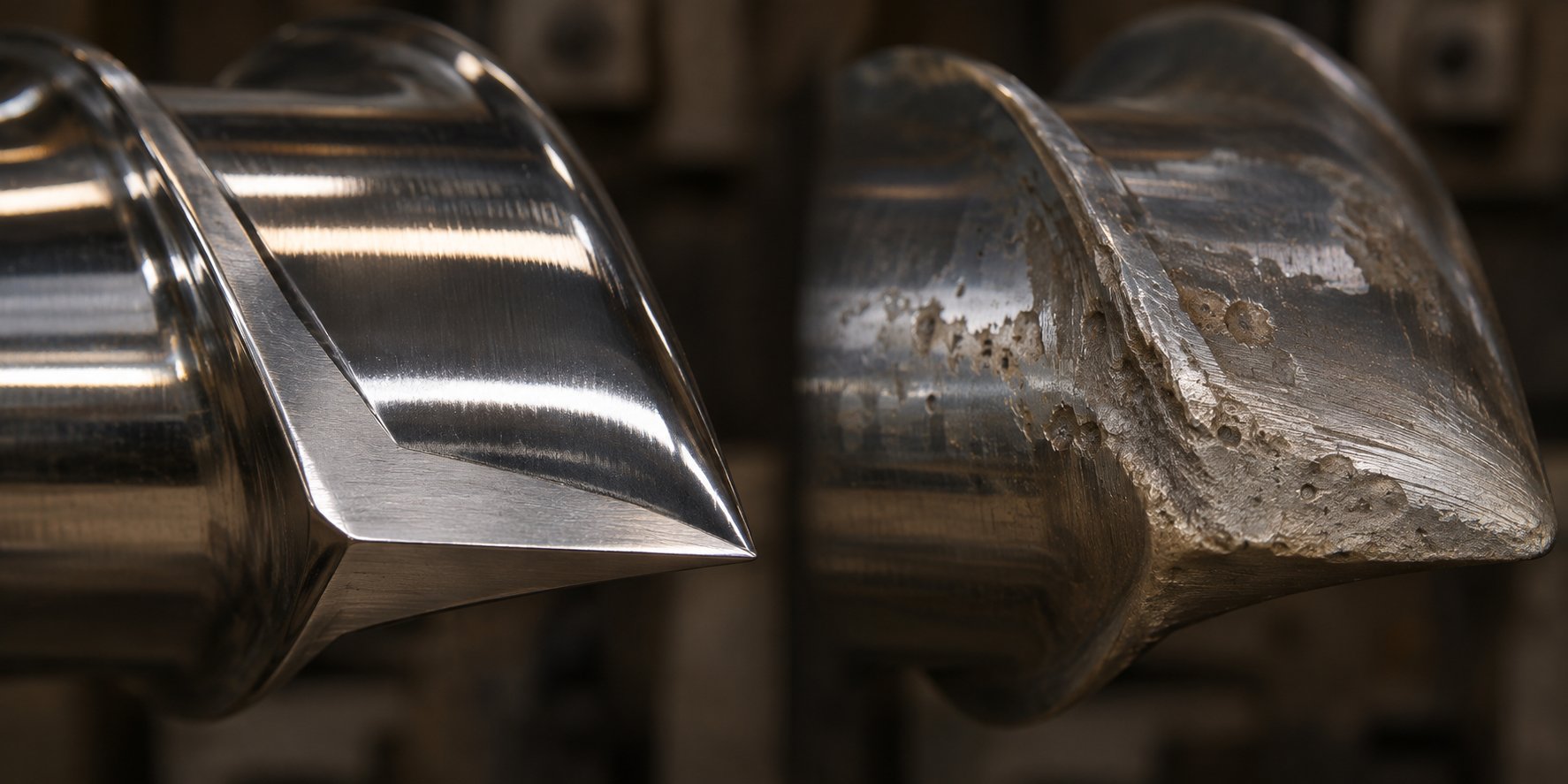
Screw Wear and Compression Ratio Degradation Over Time
A brand-new single screw extruder compression ratio of 3.2:1 does not stay 3.2:1 forever. Every revolution grinds flight lands against the barrel wall, every abrasive filler particle erodes the channel surface, and every thermal cycle fatigues the metal. The geometric dimensions printed on the original spec sheet remain fixed on paper - but inside the barrel, the effective compression ratio is quietly drifting downward, taking melt quality, throughput, and energy efficiency with it.
How Wear Shifts Effective Compression Ratio
The mechanism is straightforward. As flight tips lose material - whether through abrasive contact with fillers like glass fiber and calcium carbonate, or through corrosive attack from resins like PVC - the radial clearance between the screw and barrel wall grows. A standard guideline from Plastics Technology puts new flight clearance at the nominal screw diameter divided by 1000. For a 3.5-inch extruder, that means roughly 0.004 inches per side when new. Double or triple that clearance, and the leakage flow over the flight lands - polymer slipping backward past the flight tip instead of being pushed forward - increases dramatically.
This leakage hits hardest in the metering zone, where the channel is already at its shallowest. Imagine a metering depth of 2.5 mm with an additional 0.2 mm of clearance that was not there when the screw was manufactured. That extra gap effectively deepens the metering channel from the melt's perspective, reducing the functional compression ratio without anyone touching the feed zone. The screw rotor compression ratio vs length profile shifts: compression tapers off earlier than the designer intended, and the metering section loses its ability to pump against head pressure efficiently.
The consequences cascade. To maintain the same output rate, the operator must increase screw speed. Higher RPM generates more shear heat. Discharge temperatures climb. A real-world example from Dow research on a 100 mm extruder running 1 MI polyethylene at 150 kg/hr showed that as flight clearance increased from the original 0.005 inches per side, the screw speed had to rise continuously to hold rate - until discharge temperature approached 246 degrees C, roughly 10 degrees C above the process target. At that point, throughput had to be cut by approximately 13%, directly reducing line profitability and capacity.
Barrel bore wear compounds the problem. Over time, the barrel's inner diameter enlarges, especially in high-pressure zones near the end of the transition section and the metering zone. An iron-based bimetallic barrel liner - typically about 0.060 inches thick when new - gradually erodes. As radial clearance grows, the screw cannot develop the pumping pressure needed to maintain intended output. Higher-viscosity polymers like HDPE mask this effect longer than lower-viscosity materials like PP, which leak more readily through the same gap.
Warning Signs That Compression Performance Has Degraded
Wear is gradual - so gradual, in fact, that many plants never pull a screw for inspection until scrap rates spike or catastrophic failure occurs. A proactive approach means watching for the early indicators that effective compression has shifted. Schedule a dimensional audit of your screw and barrel whenever you observe any of the following:
- Declining output at constant screw speed. If you used to run 200 kg/hr at 80 RPM and the same settings now deliver 185 kg/hr, leakage flow over worn flights is the most likely explanation.
- Rising discharge or melt temperature without process changes. Higher clearance forces the operator to increase RPM to hold rate, and the extra speed generates additional shear heat. Even if RPM has not changed, the leakage flow itself contributes frictional heating as polymer squeezes through the enlarged gap.
- Increasing motor amperage at the same screw speed and throughput. The drive works harder to compensate for the lost pumping efficiency, a sign of degraded screw press compression ratio performance in the metering section.
- Growing reject rates from unmelts, gels, or surface defects. Worn barrier flights and mixing sections lose their ability to separate solids from melt and to disperse unmixed pockets - problems that mimic a too-low geometric ratio.
- Visible wear on the hard facing when the screw is pulled. If the stellite or colmonoy hard facing on flight tips is worn through to base metal, the clearance has far exceeded design intent.
- Cyclic output surging that was not present when the screw was new. As wear progresses unevenly along the screw length, local compression imbalances create the same solid-bed instability described in the troubleshooting chapter.
A simple field check: measure the screw's outside diameter at multiple points along its length using a micrometer. Compare readings to the nominal OD. Industry practice considers a flight clearance reaching four times the original tolerance as the threshold for replacement - but this is a guideline, not a universal rule. Critical-duty processes like medical tubing may warrant action at two times the original clearance, while non-critical applications like corrugated pipe can tolerate significantly more wear before quality suffers.
Replacement, Refurbishment, or Redesign — Making the Right Call
When the dimensional audit confirms that wear has degraded your effective compression ratio, three paths open up: replace with an identical screw, refurbish the existing one, or redesign the geometry entirely.
Refurbishment is typically the fastest and most cost-effective option when wear is moderate. The process involves grinding the screw to a uniform undercut diameter, re-welding flight tips with a hardfacing alloy (such as Colmonoy 56 or a tungsten-carbide blend), and then grinding the OD back to original tolerances. Experienced screw manufacturers report that screws can be rebuilt multiple times when high-quality welding practices are followed. A conservative industry guideline caps refurbishment at three cycles, since repeated weld overlay can degrade the base metal and increase delamination risk - though some specialists achieve six to eight rebuilds with careful metallurgical management. For barrels, bore grinding to restore roundness followed by re-nitriding or hard chrome plating can extend service life, and a bimetallic barrel liner typically lasts about three times as long as a screw before needing replacement.
Like-for-like replacement makes sense when the original design was well matched to the resin and process, and the screw has reached the end of its refurbishment life. Keep a spare screw in storage so the swap can happen during a planned shutdown rather than an emergency, minimizing lost production hours.
Redesign is the smartest choice when wear reveals that the original compression ratio was never ideal in the first place - a surprisingly common scenario. Many processors inherit screws that were spec'd for a different resin family, a different throughput target, or a different era of production requirements. If your material mix has shifted toward recycled content, if you have added fillers that were not in the original brief, or if output targets have climbed beyond the screw's design envelope, rebuilding to the same geometry just perpetuates a suboptimal setup. This is where engaging a screw engineering partner pays for itself. NANHAIYA's custom screw design service, for example, has their engineers evaluate flight depths, compression ratios, mixing section geometry, base materials, and surface treatments against your specific polymer behavior, machine dimensions, and production targets before manufacturing. For processors facing the replace-versus-redesign decision, that application-specific review can mean the difference between installing another compromised screw and getting one that actually matches the job.
Whichever path you choose, the underlying lesson is the same: compression ratio is not a set-and-forget specification. It is a living parameter that drifts with every production hour. Monitoring it - through baseline measurements, periodic dimensional audits, and attention to the warning signs listed above - is what separates reactive maintenance from proactive process control.
With wear management addressed, the final piece of the puzzle is a decision framework that ties every concept in this article together - from polymer selection and process type to machine condition and production goals - into a practical checklist you can use the next time you spec, troubleshoot, or upgrade a screw.
How to Select the Right Screw Compression Ratio for Your Application
Knowing the formula, the polymer tables, the extrusion-versus-molding distinctions, and the wear patterns is valuable - but none of it helps unless you can pull the right thread at the right moment on the production floor. Processors rarely encounter compression ratio as an abstract concept. It surfaces inside four very specific, very practical scenarios: specifying a screw for new equipment, diagnosing problems on an existing line, switching resins without changing hardware, or integrating regrind and recycled content into production. Each scenario demands a slightly different evaluation sequence, but all four draw from the same core logic.
Decision Framework for Four Common Processing Scenarios
Scenario 1 — Specifying a Screw for a New Machine
This is the cleanest starting point because nothing is constrained by legacy hardware. You are selecting compression geometry from scratch, so every variable is on the table. Start by identifying the primary polymer and its morphology. A semi-crystalline resin like PA66 with its sharp melt transition and high crystallinity needs aggressive compaction - ratios of 3.5:1 to 4.5:1. An amorphous material like ABS demands gentler treatment, typically 2.0:1 to 2.5:1. From there, confirm whether the machine is a continuous extruder or a reciprocating injection molder, since the process type shifts the ideal range downward for molding applications where backpressure shares the melt-quality burden. Factor in any special barrel features - a grooved feed section, for example, may call for a lower geometric ratio because the barrel itself handles much of the solids conveying. Finally, specify flight materials and surface treatments based on the resin's abrasiveness and corrosiveness.
Scenario 2 — Troubleshooting an Existing Process
Here, the screw is already installed and something has gone wrong. Resist the urge to start adjusting barrel temperatures or screw speed before asking the geometric question first. Pull the screw if possible and physically measure the feed and metering channel depths. Compare the calculated ratio against the polymer-specific recommendations. As Jim Frankland of Frankland Plastics Consulting emphasizes, screw performance is often compromised when processors do not consider the most influential variables behind the compression ratio - and a worn or mismatched geometry is frequently the root cause that no process tweak can fully compensate. Check for wear-induced clearance growth, especially in the metering zone, which silently lowers the effective ratio over thousands of production hours. Only after confirming the geometric match should you move on to optimizing temperature profiles and speeds.
Scenario 3 — Switching Materials on the Same Screw
Budget constraints often force processors to run multiple resins on a single screw. The risk is real. A screw designed for ABS at 2.5:1 will undercompress HDPE, which needs 3.0:1 or higher, leaving the metering zone starved and output unstable. Conversely, running low-viscosity PP on a screw designed for high-crystallinity nylon can generate excessive shear heat that degrades the polypropylene. Dow research case studies documented exactly this dynamic: an ABS screw with a 3.1:1 ratio caused process instability because the ratio was too aggressive for that amorphous resin, while a PS screw at 2.4:1 allowed entrained air to create splay defects because the ratio was too gentle. Before switching materials, compare the new resin's recommended range to the installed screw's measured ratio. If the gap exceeds half a point, expect compromised performance - and plan accordingly with process adjustments or a screw change.
Scenario 4 — Processing Regrind or Recycled Content Blends
This is the scenario where standard compression ratio tables break down most dramatically. Regrind and post-consumer recyclate arrive with lower, more variable bulk densities than virgin pellets. Irregular flake geometry traps extra air, and contamination alters melt viscosity unpredictably. As Frankland notes, the feeding properties of recyclate may conflict with the melting requirements - a low-bulk-density regrind may need more feed depth, yet the standard ratio for that polymer would produce insufficient shear heating. Mixed polymer recycling streams - like the PP/HDPE blends increasingly common in post-consumer packaging recovery - completely change the compression calculation because the two polymers differ in both their solid-state properties and their energy requirements. The only reliable approach is measuring actual bulk density of each incoming batch and determining feeding and melting requirements separately rather than relying on published ratios.
Compression Ratio Selection Checklist
Regardless of which scenario you face, the evaluation follows a consistent logical sequence. Use this checklist every time you specify, audit, or reconsider a screw's compression geometry:
- Identify the polymer's morphology and bulk density. Semi-crystalline resins undergo a larger volume change during melting and generally require higher ratios. Measure bulk density directly for regrind or recycled feedstocks rather than assuming virgin values.
- Calculate the target compression ratio from the polymer reference table. Cross-reference the resin family's recommended range with any grade-specific data from the material supplier. For unfamiliar or custom-compounded resins, err toward the middle of the range and plan to fine-tune.
- Adjust for process type. If the application is injection molding, shift the target toward the lower end of the range - backpressure and screw-back speed provide supplemental melt-quality control that extrusion lacks.
- Verify that screw zone proportions match the material's melting behavior. A polymer with a narrow melting range (like HDPE) benefits from a shorter, steeper transition zone, while a gradually softening amorphous resin (like PC) needs a longer, gentler compression taper. The ratio alone does not capture this - zone lengths matter too.
- Consider barrier or mixing geometry if melt quality demands are high. Applications requiring optical clarity, tight gauge tolerance, or high color uniformity may need a barrier screw or an added mixing section to achieve what a simple three-zone design cannot, even at the correct geometric ratio.
- Confirm barrel condition. Measure barrel bore diameter and screw flight OD. If wear has pushed flight clearance beyond two to four times the original tolerance, the effective ratio has degraded regardless of what the screw's spec sheet says. Address wear before blaming the design.
- Document and baseline. Record the measured dimensions, calculated ratio, and key process parameters (output rate, melt temperature, motor load) at startup. This baseline becomes your diagnostic reference point for every future audit.
Screw compression ratio is the starting point of screw design, not the finish line. Optimizing it requires evaluating polymer behavior, process type, machine condition, and production targets together - because the ratio only delivers its intended performance when every surrounding variable supports it.
When to Engage a Custom Screw Design Partner
Many compression ratio decisions are straightforward enough to handle in-house with the framework above. A standard PE blown-film screw at 3.0:1 on a well-maintained extruder does not need outside engineering. But certain situations genuinely benefit from specialist support:
- You are processing a polymer or blend with no established compression ratio data - biopolymers, recycled mixed streams, or highly filled compounds where published tables simply do not apply.
- A wear audit reveals that the original screw's ratio was never well matched to your current material mix, and rebuilding to the same spec would perpetuate the mismatch.
- You need to balance competing demands - high throughput on a heat-sensitive resin, or consistent melt quality across frequent material changeovers - that a single standard three-zone geometry cannot satisfy.
- Your process requires barrier flights, specialized mixing sections, or grooved-feed barrel integration, and you need the screw's compression profile engineered as part of a complete system rather than selected from a catalog.
In these cases, working with a screw engineering team that evaluates the full picture - polymer rheology, machine dimensions, temperature constraints, and production goals - prevents expensive trial-and-error on the factory floor. NANHAIYA's custom screw design service is built around exactly this approach: their engineers assess flight depths, compression ratios, mixing sections, base materials, and surface treatments against your application-specific demands before moving to manufacturing. The scope covers screw and barrel engineering for both extrusion and injection molding platforms, connecting directly to the decision framework outlined above. For teams that have worked through the checklist and landed on questions the checklist alone cannot answer, that kind of application-level review turns uncertainty into a screw geometry that actually fits the job.
Whether you handle the selection internally or bring in outside expertise, the principle stays the same. Understanding what screw compression ratio is, how to calculate it, and how it interacts with every other variable in the plasticating system gives you the diagnostic vocabulary to make better hardware decisions, faster troubleshooting calls, and more confident material transitions. The ratio is just a number - but it is the number that everything else in your screw's performance is built around.
Frequently Asked Questions About Screw Compression Ratio
1. How do you calculate compression ratio for screws?
Measure the channel depth in the feed zone (from the screw root to the flight tip) and the channel depth in the metering zone using a depth gauge or vernier caliper. Divide the feed channel depth by the metering channel depth. For example, a feed depth of 8.0 mm and a metering depth of 2.5 mm yields a compression ratio of 3.2:1. Always take multiple readings in each zone and average them, since manufacturing tolerances and wear can cause slight variation along the screw length.
2. What is a good compression ratio for an extrusion screw?
The ideal ratio depends on the polymer being processed. Semi-crystalline resins like HDPE typically require 3.0:1 to 4.5:1 because they undergo a large density change during melting. Amorphous polymers like ABS or polycarbonate perform well at 2.0:1 to 2.8:1 since their density change is smaller. Heat-sensitive materials such as rigid PVC need low ratios of 1.5:1 to 2.5:1 to prevent thermal degradation. Dow Inc. research found that LLDPE achieved the best balance of throughput and melt quality near 2.8:1 on standard three-zone screws.
3. What is the difference between screw compression ratio and screw compressor compression ratio?
These are entirely unrelated concepts sharing similar terminology. Screw compression ratio in plastics processing refers to the ratio of feed-zone channel depth to metering-zone channel depth on a plasticating screw, governing how polymer is compacted and melted. Screw compressor compression ratio, used in refrigeration and HVAC, describes the gas pressure ratio between the discharge and suction ports of a rotary screw compressor. One deals with solid-to-melt polymer transitions; the other deals with gas volume reduction.
4. Why does screw compression ratio matter for injection molding?
In injection molding, the screw both plasticates material and acts as a plunger during injection. Because backpressure and screw-back speed provide additional melt-quality control that continuous extrusion lacks, injection molding screws typically use moderate ratios of 2.0:1 to 3.0:1. A ratio that is too high generates excess shear heat during recovery, which continues building during cooling and idle portions of the cycle. This extended residence under compression can cause degradation, discoloration, or property loss - especially in heat-sensitive resins like PET or PVC.
5. How does screw wear affect the compression ratio over time?
As flight tips erode and barrel bores enlarge through abrasive or corrosive wear, the radial clearance between screw and barrel increases. This extra gap allows more melt to leak backward over the flight lands, effectively reducing the compression the polymer experiences in the metering zone. Symptoms include declining output at constant RPM, rising melt temperature, increased motor amperage, and growing reject rates. Industry practice recommends a dimensional audit when flight clearance reaches two to four times the original tolerance, at which point refurbishment, replacement, or a full screw redesign through a specialist like NANHAIYA (nhyscrews.com/services/custom-screw-design) may be warranted.
Written by
Nanhaiya Technical Team
Zhoushan Nanhaiya Plastic Machinery Co., Ltd.
The Nanhaiya technical team supports screw and barrel manufacturing projects through application review, technical communication, custom manufacturing coordination, and production and quality control.
Discuss Your Application
Related Articles
More insights on screw barrel technology and plastics processing.

Injection Molding Color Mixing: From Streaks to Flawless Consistency
Nov 19, 2026
Master injection molding color mixing with expert guidance on colorant types, screw design, process parameters, defect troubleshooting, and Delta E QC protocols.
Read Article
Wrong Extruder Breaker Plate? Spot the Signs Before Scrap Piles Up
Nov 19, 2026
Learn how to select, size, and maintain your extruder breaker plate. Covers hole geometry, pressure drop, polymer-specific specs, and troubleshooting tips.
Read Article
Injection Molding Melt Temperature: Why Your Barrel Settings Lie
Nov 19, 2026
Learn why barrel set points lie about injection molding melt temperature. Complete resin chart, measurement methods, defect troubleshooting, and optimization steps.
Read ArticleLooking for something else?
Search by material, symptom or product and jump straight to the relevant page.
These are navigation suggestions based on keyword matching — not a quotation, not a delivery commitment, and not a substitute for engineering review. Final specification is confirmed by our engineers against your drawings and processed material.
Need help with screw barrel selection?
Share your machine model, processed material and application. Our team can help with pricing and technical support.