

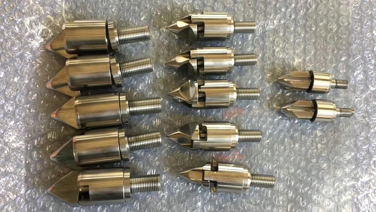
What Is a Screw Tip Assembly and Why It Matters
Imagine a tiny gatekeeper sitting at the very front of your injection molding screw. Its job sounds simple: let molten plastic flow forward when needed, then slam shut to prevent any backflow when the screw pushes that melt into the mold. In practice, this gatekeeper — the screw tip assembly — is one of the most performance-critical components on the entire machine. When it works well, shots land consistently and parts come out right. When it wears out, every cycle becomes a gamble.
Defining the Screw Tip Assembly in Injection Molding
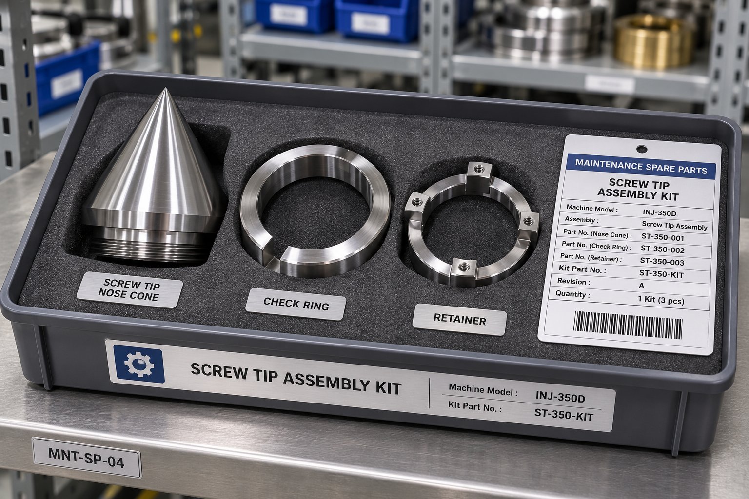
A screw tip assembly is the multi-component unit threaded onto the front end of an injection molding screw. It consists of a streamlined tip (nose cone), a check element such as a sliding ring or ball valve, and a retainer seat. Together, these parts form a one-way valve that permits melt to flow forward during plasticization while sealing against backflow during the injection and pack/hold phases of the molding cycle.
That definition covers a lot of ground, so let's break it down. During screw recovery, the screw rotates and conveys resin forward. The check element inside the assembly opens, allowing melt to accumulate in front of the screw. The moment injection begins, the screw drives forward like a plunger. The check element seats against the retainer, creating a seal that forces melt into the mold cavity instead of allowing it to leak backward over the screw flights. This open-close-seal sequence repeats every single cycle — thousands of times per day on a production machine.
Whether you're running a compact 13 mm barrel on a micro-molding press or large-format 110mm screw tip assemblies on a high-tonnage machine, the principle is identical. The injection molding screw tip assembly is the last checkpoint between your plasticizing process and the mold cavity. Its condition directly shapes the quality of every part you produce.
Why This Component Demands Attention
You'll notice that many molding operations treat this assembly as a simple wear part — something swapped out only after problems become obvious. As industry specialists at SpiraMelt have noted, the screw and valve is the heart of any injection molding operation and, more than any other component, can determine overall part quality and have a major influence on profitability. Yet many firms do not fully understand non-return valve design or its impact on production.
The direct link between this assembly's condition and your bottom line comes down to three factors:
- Shot-to-shot consistency: A properly sealing check valve ensures the same volume of melt enters the mold on every cycle. Even slight wear on the sealing surfaces allows melt to leak backward, causing cushion drift and unpredictable part weights.
- Scrap rates: Worn assemblies force technicians to chase process parameters — raising pressures here, adjusting speeds there — which often creates new defects while masking the root cause. Short shots, flash, splay, and black specks can all trace back to a degraded tip or check ring.
- Cycle-time stability: When the valve no longer seals reliably, pack and hold phases become less effective. Operators may extend hold times or increase pressures to compensate, quietly inflating cycle times and eroding throughput.
The challenge is that wear happens gradually. A check ring doesn't fail overnight — it loses fractions of a thousandth of an inch over weeks and months, slowly widening the gap between acceptable and unacceptable performance. By the time defects become visible on finished parts, the assembly may have been underperforming for far longer than anyone realized.
This article serves as a process-engineering reference that pulls together everything you need to know about this critical assembly — from component anatomy and design comparisons to installation procedures, failure diagnosis, and replacement sourcing. Each section builds on the last, giving you a practical framework for keeping this small but mighty component in peak condition.
Anatomy of Every Component Inside the Screw Tip Assembly
Knowing that this assembly governs shot consistency is one thing. Understanding exactly which piece does what — and how a fraction of a millimeter of wear on any single surface changes the entire sealing dynamic — is where real diagnostic ability begins. Think of it like understanding the parts of an engine rather than just knowing the car won't start. When you can name each component, describe its role, and visualize how it moves during the cycle, you'll troubleshoot faster and make smarter replacement decisions.
A screw tip assembly typically contains three primary components — sometimes four, depending on the design variant. Each one plays a distinct role in controlling the direction and containment of molten resin. Whether you're working with compact 18mm screw tip assemblies on a small-tonnage press or full-size assemblies on a large-diameter barrel, the functional architecture follows the same logic.
Core Components — Tip, Check Ring, and Retainer
Every component in the assembly serves a purpose tied directly to melt flow control. Here's what you'll find when you pull the screw and look at the front end:
- Screw tip (nose cone): The streamlined front piece that threads onto the screw body and guides molten resin around and through the assembly during plasticization — its tapered geometry prevents material from hanging up and stagnating, which would otherwise lead to thermal degradation and contamination.
- Check ring (sliding ring) or ball/poppet element: The moving component that acts as the actual valve — it slides or shifts to an open position during screw recovery, allowing melt to flow forward past the tip, then seats rearward during injection to block backflow and seal the shot volume in front of the screw.
- Retainer (rear seat): The stationary ring or seat surface that threads onto or locks against the screw body behind the check element — it provides the precision-machined sealing face against which the check ring or ball closes, and the quality of this metal-to-metal contact determines how effectively the valve prevents leakage.
Some designs include a fourth piece: a separate front seat machined from a harder, more wear-resistant alloy than the tip body itself. As noted in technical documentation on non-return valve configurations, a four-piece setup allows material selection flexibility — you can use a tougher alloy on the high-wear seating surface without changing the entire tip. This is particularly relevant for 13mm Engel screw tip assemblies and other compact configurations where every millimeter of the sealing interface matters.
Imagine holding all three (or four) pieces in your hand. The tip threads into the screw nose at the front. The check ring slides freely over the tip body between the front and rear seats. The retainer locks onto the screw behind the ring, creating a defined pocket within which the check element travels. There are no springs in a standard sliding-ring design, no electronics, no actuators — just precision geometry and the pressure dynamics of the melt itself driving the valve open and closed.
How the Assembly Behaves During Each Cycle Phase
These components don't just sit there. They interact in a tightly choreographed sequence every single cycle, and understanding that sequence is essential for diagnosing problems when something goes wrong.
Plasticization (valve open, melt flows forward): The screw rotates inside the heated barrel, conveying pellets forward through progressively shallower flights. Friction and external heaters melt the resin as it advances. At the front of the screw, melt pressure pushes the check ring forward on the tip body, opening a flow path between the ring and the retainer seat. Molten plastic streams through this gap and accumulates in the space ahead of the screw tip. The growing melt pool pushes the screw rearward against the machine's back pressure setting — typically 500 to 750 psi plastic pressure for unfilled resins. Throughout this entire recovery phase, the valve remains open, and material flows freely forward.
Injection (valve closes, melt is pushed into the mold): The screw stops rotating and rams forward axially, acting as a plunger. This sudden forward thrust reverses the pressure relationship — melt ahead of the screw is now being compressed, while the ring experiences a rearward force. The check ring snaps backward against the retainer seat, sealing the flow path. Two critical seals must form simultaneously: one between the ring's rear face and the retainer's machined seat surface, and another between the ring's outer diameter and the barrel bore wall. Pressures acting on this assembly during injection can reach 20,000 to 45,000 psi, particularly when filling thin-walled parts. Any gap in either seal allows melt to leak backward over the screw flights instead of entering the mold.
Pack/hold (valve remains sealed, pressure maintains packing): After the mold cavity fills, the screw maintains forward pressure to compensate for volumetric shrinkage as the part cools. The check ring stays firmly seated against the retainer throughout this phase, keeping the melt column pressurized and preventing any rearward migration. The duration and magnitude of this pack pressure directly influence part density, dimensional accuracy, and surface quality — all of which depend on the valve holding a leak-free seal from the moment injection begins until hold time expires.
Here's the key insight: the transition between the open and closed states isn't instantaneous. During the brief interval when the screw shifts from rotating to ramming forward, the check ring must travel from its forward open position all the way back to its seat. That transition window — often just fractions of a second — represents a period of partial seal where some backflow can occur even on a perfectly new assembly. Wear amplifies this window. A ring that's lost material on its seating face or outer diameter takes longer to achieve a full seal, and the leakage during that transition grows with every thousand cycles.
Thread Interface and Screw Engagement
The way the assembly attaches to the screw body is a detail that's easy to overlook — until it causes a problem. The screw tip threads onto the screw nose (the machined end of the screw shaft), and this threaded interface is the structural anchor for the entire assembly. If the threads are damaged, cross-threaded, or galled from dissimilar metals and thermal cycling, several things can go wrong.
Poor thread engagement affects concentricity — the alignment of the tip, ring, and retainer relative to the barrel bore centerline. Even slight misalignment means the check ring doesn't sit squarely against the retainer seat, creating a crescent-shaped gap on one side where melt escapes. You'll see the evidence as asymmetric wear patterns on the ring when you pull it during inspection.
Thread condition also determines how cleanly you can remove the assembly for maintenance. Galled or seized threads — common when anti-seize compound was skipped during the last installation — can turn a routine screw pull into a multi-hour ordeal requiring heat, penetrating lubricant, and sometimes destructive removal. For machines processing 18mm Demag screw tip assemblies or similarly compact configurations, the smaller thread diameters are especially vulnerable to damage from over-torque or improper tooling.
The register — the flat mating surface where the retainer contacts the screw body — also matters. This face must sit flush and square to maintain the seat geometry. A burred or mushroomed register surface, often caused by previous over-torquing, changes the effective seat angle and undermines seal quality from the very first shot after reassembly.
With every component named, its function defined, and the cycle-phase choreography mapped out, the natural question becomes: are all these assemblies built the same way? Not even close. The sliding ring described here is just one of several fundamentally different design approaches — each with distinct advantages, limitations, and ideal use cases.
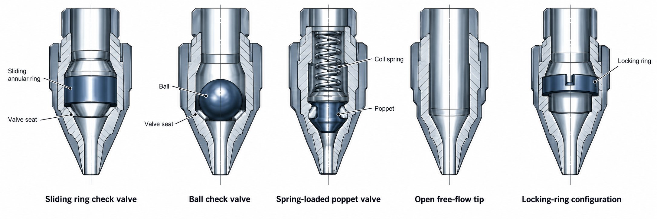
Five Screw Tip Assembly Types Compared
The sliding-ring design described in the anatomy section is just the starting point. Injection molding covers an enormous range of resins, part geometries, barrel sizes, and precision requirements — and no single valve configuration handles every scenario optimally. Some applications need the fastest possible shut-off to prevent backflow of water-thin nylon melts. Others prioritize streamlined flow paths to protect shear-sensitive PVC compounds. Still others demand easy disassembly for rapid color changes on a busy production floor.
Five primary design families cover the vast majority of what you'll encounter in the field. Understanding how each one seals, flows, and wears gives you a practical framework for matching the right screw tip assembly to your specific process — instead of simply running whatever happened to ship with the machine.
Sliding Ring Check Valve — The Industry Standard
If you pulled screws from a hundred injection molding machines at random, the majority would be fitted with a sliding-ring check valve. There's a good reason for that dominance: this design offers the broadest compatibility across resin types, barrel sizes, and processing conditions. Industry specialists consistently recommend it as the default starting point because it is the most versatile and durable, with the fewest drawbacks in general use.
The mechanics are straightforward. A free-floating ring slides forward during recovery to open the melt path, then seats rearward against the retainer during injection. Because the ring does not rotate with the screw — it only translates axially — wear on the barrel bore is minimized compared to designs where the sealing element spins. This characteristic makes the sliding ring especially forgiving in long production runs.
Within this family, you'll find three-piece and four-piece variants. The three-piece integrates the front seat into the retainer body, while the four-piece uses a separate, harder-alloy front seat. That extra piece may sound like added complexity, but it extends service life significantly: the high-wear contact surface can be manufactured from a premium tool steel or carbide grade without driving up the cost of the entire assembly. For shops running abrasive glass-filled or mineral-filled resins, the four-piece sliding ring has become the go-to configuration.
Pros
- Widest resin compatibility — handles everything from commodity polyolefins to engineering-grade nylons and polycarbonates
- Ring does not rotate with the screw, reducing barrel bore wear
- Simple disassembly for inspection and maintenance
- Available across virtually all barrel diameters, from compact setups to large-format 110 mm machines
Cons
- Shut-off is not instantaneous — the ring must travel from its forward open position to the rear seat, creating a brief transition window where some backflow occurs
- On very low-viscosity melts, that transition window can allow enough leakage to affect shot consistency
Ball Check and Poppet Valve Designs
When barrel diameters shrink — think Engel 13mm screw tip assemblies used in micro-molding or compact 18 mm configurations on small-tonnage Demag presses — there's often not enough radial space for a sliding ring to function effectively. Ball check valves solve this problem with a fundamentally different sealing approach.
Instead of a ring sliding axially along the tip body, a ball (or similar spherical element) floats inside a housing within the tip. During recovery, melt pressure nudges the ball off its seat, opening a flow path. During injection, the ball drops back into its tapered seat and plugs the flow hole. The geometry is compact, the moving mass is small, and the shut-off action is fast.
Because of their simplified internal geometry, ball checks are generally better for processing highly sensitive materials like polycarbonate and acrylic. They also provide a more positive shutoff when dealing with low-viscosity resins or small shot sizes, where even minor leakage during transition would represent a significant percentage of the total shot volume.
Poppet valves take the concept further by using a spring-assisted or pressure-assisted poppet element instead of a free-floating ball. The spring provides a positive closing force that doesn't rely solely on melt pressure reversal to seat the valve. This makes poppet designs — sometimes called quick shut-off (QSO) valves — especially effective for resins with very low melt viscosity, where a passive ball or ring might not seat fast enough to prevent meaningful backflow.
There is a trade-off to be aware of, though. Both ball check and poppet designs share a characteristic that separates them from sliding-ring valves: their sealing outer diameter rotates with the screw during plasticization. As process engineering expert John Bozzelli has cautioned, this rotation introduces the likelihood of premature barrel bore wear — a concern that grows more significant the longer these assemblies stay in service. For Battenfeld screw tip assemblies and Cincinnati screw tip assemblies running long campaigns, this wear pattern should be factored into maintenance planning.
Free-Flow Tips and Locking-Ring Configurations
Not every molding scenario requires a check valve at all. Free-flow tips — sometimes called open tips — eliminate the check element entirely. There's no ring, no ball, and no poppet. Melt flows freely through a streamlined tip body in both directions.
Sounds counterproductive? In certain situations, it's exactly the right approach. Intrusion molding processes, where the screw continuously rotates and pushes melt into a partially open mold, don't involve the abrupt injection stroke that demands backflow prevention. Vented barrels — where a decompression zone allows volatiles to escape mid-barrel — also use free-flow tips because a check valve would interfere with the pressure profile needed for proper venting. And some two-stage injection systems, where melt is transferred from a plasticizing barrel to a separate shot pot with its own plunger, don't need a check valve on the plasticizing screw at all.
The benefits here are obvious: no sealing surfaces to wear, no transition window, no parts to inspect or replace, and the fastest possible color or material changes since there are no tight clearances to trap residual resin. The limitation is equally obvious — you can't use an open tip on a conventional single-stage injection process and expect consistent shot sizes.
Locking-ring designs sit at the opposite end of the spectrum. Popular with many Japanese OEMs, the locking ring (sometimes called a castle tip) is a variant of the check-ring concept, but with the ring keyed into the retainer so it rotates with the screw instead of floating independently. The idea is that this keyed engagement promotes more consistent seating alignment.
However, the same barrel-wear concern that applies to ball check and poppet valves applies here — because the check ring's sealing OD rotates with the screw, it acts like a bearing surface against the barrel bore, accelerating ID wear over time. Proponents argue the seal quality is superior; critics point to evidence of significant barrel scoring after relatively few operating hours. For high-precision or high-pressure applications where shot-to-shot repeatability is the overriding priority and barrel replacement costs are accepted, locking-ring assemblies remain a viable choice — but you'll want to monitor barrel bore diameter closely.
Side-by-Side Design Comparison
Every design involves trade-offs. The following table distills the key performance criteria across all five screw tip assembly types, giving you a single reference for evaluating which configuration fits your application:
| Criteria | Sliding Ring Check | Ball Check | Poppet (QSO) | Free-Flow / Open Tip | Locking Ring |
|---|---|---|---|---|---|
| Backflow Prevention | Good — slight transition delay | Very good — fast seating in small bores | Excellent — spring-assisted positive shut-off | None — no check mechanism | Very good — keyed ring alignment aids seating |
| Shear Sensitivity | Moderate — ring gap can generate some shear | Low — simplified internal flow path | Low to moderate — depends on orifice sizing | Lowest — fully streamlined flow | Moderate — locking teeth may partially restrict flow |
| Ease of Maintenance | High — simple disassembly, few parts | Moderate — housing access varies by design | Moderate — spring and poppet add complexity | Highest — no valve components to service | Moderate — keyed engagement adds reassembly steps |
| Color / Material Change Speed | Good — ring clearance allows purge flow | Slower — internal cavities can trap pigment | Slower — spring pocket and poppet seat trap resin | Fastest — no internal pockets or clearances | Good — similar to sliding ring in most cases |
| Suitability for Filled Resins | Very good — 4-piece variant with hardened seat excels | Limited — ball and seat erode faster under abrasion | Limited — poppet seat vulnerable to abrasive wear | Good — no sealing surfaces to erode | Good — but barrel bore wear from rotation accelerates with fillers |
| Barrel Bore Wear Risk | Low — ring does not rotate with screw | Elevated — sealing OD rotates with screw | Elevated — sealing OD rotates with screw | Lowest — no contact element | Elevated — ring rotates with screw |
| Typical Barrel-Size Range | All sizes — 18 mm to 110 mm+ | Best suited for small diameters (13 mm to ~40 mm) | Small to mid-range (13 mm to ~60 mm) | All sizes where check valve is not required | Mid to large — common on Japanese OEM machines |
A few patterns stand out in that comparison. The sliding ring emerges as the lowest-risk, broadest-application choice — which explains its market dominance. Ball check and poppet valves earn their place in niche roles where small barrel diameters or very low melt viscosity make their faster shut-off essential. Free-flow tips serve specialized processes where no valve is needed. And locking-ring configurations offer precision sealing for shops willing to accept the barrel-wear trade-off and plan for it in their maintenance schedules.
Choosing the right design, however, isn't just about matching a valve type to a barrel size. The real performance story unfolds during injection and pack-hold, when the assembly must seal against pressures that can exceed 40,000 psi. How effectively that seal forms — and how quickly it degrades — depends on understanding the backflow prevention mechanism at a deeper level than any comparison table can capture.
How the Non-Return Valve Prevents Backflow in Injection Molding Screw Tip Assemblies
Design comparisons tell you what each valve type looks like and where it fits best. But the real question — the one that determines whether your parts come out right — is how effectively any given valve seals when it matters most. That sealing event happens under extreme pressure, in a fraction of a second, and it repeats thousands of times a day. Understanding the mechanics behind it turns backflow prevention from an abstract concept into something you can diagnose, measure, and manage on the production floor.
Here's the fundamental challenge. During plasticization, the screw rotates and acts like an Archimedean pump, conveying molten resin forward through progressively shallower flights. Melt accumulates ahead of the screw tip, and the growing pressure pushes the screw rearward. So far, so good — material is flowing in the right direction. But the moment injection begins, the screw's role changes completely. It stops rotating and rams forward axially, acting as a plunger to force that accumulated melt through the nozzle and into the mold cavity.
Without a functioning non-return valve, this plunger action would simply push melt in both directions — forward into the mold and backward over the screw flights. You'd lose volume, lose pressure, and lose any hope of repeatable shot sizes. The check valve inside the screw tip assembly exists to solve this exact problem, converting the screw from a two-way pump into a one-way delivery system the instant injection begins.
The Seal Mechanism During Injection and Pack-Hold
Whether your assembly uses a sliding ring, a ball, or a poppet, the sealing principle follows the same logic. When the screw drives forward, the pressure reversal forces the check element rearward against its seat on the retainer. Metal meets metal, and two simultaneous seals must form: one between the check element's rear face and the retainer's precision-machined seat surface, and another between the element's outer diameter and the barrel bore wall.
Think of it like pressing your thumb over the end of a garden hose. If your thumb sits perfectly flat and covers the opening completely, water stops. If there's even a tiny gap — a wrinkle in your skin, a chip on the hose lip — water squirts through. The injection molding version of that gap involves clearances measured in thousandths of an inch and pressures that can reach 20,000 to 45,000 psi during thin-wall filling. At those pressures, even microscopic wear on the seating surfaces allows melt to leak backward.
What does that leakage look like in practice? As process specialists at Turner Group have emphasized, modern injection molding machines can control screw position, velocity, and pressure with exceptional precision — but that precision only translates into the molded part if the intended volume of material is consistently transferred into the mold. A machine may repeat the exact same screw stroke, yet the actual material delivered to the cavity changes from shot to shot because melt is bleeding past a worn check ring during injection. The screw reaches the same position, but the mold doesn't receive the same amount of plastic.
This is why cushion position — the screw's location at the end of pack-hold — becomes such an important diagnostic indicator. A consistent cushion means the valve is sealing repeatably. A wandering cushion, even by a few thousandths of an inch, signals that leakage is stealing material from the shot. And because this wear develops gradually, the drift can be subtle enough to escape notice until parts start failing dimensional checks or weight specifications.
The pack-hold phase amplifies the problem. After the cavity fills, the screw maintains forward pressure to compensate for volumetric shrinkage as the part cools. If the valve leaks during this critical phase, packing pressure bleeds off rearward instead of densifying the part. You'll see the results as sink marks, dimensional variation, and reduced part weight — defects that look like a process-parameter issue but actually originate in a mechanical seal that's lost its integrity.
Valve seal quality is the single largest variable in shot-to-shot consistency outside of hydraulic or servo repeatability. A machine can have perfect control algorithms, perfectly tuned PID loops, and a flawless mold — but if the non-return valve leaks, none of that precision reaches the part.
Decompression Settings and Valve Interaction
One of the most overlooked variables in injection molding is how decompression — also called suck-back — interacts with the condition and design of the screw tip assembly. After recovery completes and the screw has built its shot, most processes include a brief rearward movement of the screw to relieve residual melt pressure in the nozzle. This prevents drool from the nozzle tip between cycles and avoids stringing when the mold opens.
Sounds straightforward, but the magnitude of that decompression stroke creates a ripple effect through the valve assembly. When the screw retracts, it creates a slight vacuum in the melt pool ahead of the tip. On OEM injection molding screw tip assemblies with a tight, well-maintained seal, this controlled suction pulls the melt cushion back just enough to relieve pressure without introducing air. The valve stays closed during suck-back because no forward melt flow exists to push the check element open.
A worn assembly changes the equation. If the check ring no longer seats tightly against the retainer, the decompression stroke can pull air past the compromised seal and into the melt pool. That ingested air shows up in the next shot as splay — silver streaks on the part surface that look like moisture defects but resist every drying adjustment you throw at them. You'll chase dryer settings, vent temperatures, and material moisture content for days before someone thinks to pull the screw and inspect the check ring. The Nissei screw tip assemblies commonly found on precision-molding platforms are particularly unforgiving in this regard — their tight-tolerance processes leave little room for air ingestion before splay becomes visible.
The interaction works in the other direction, too. A poppet-style valve with spring-assisted shut-off creates a much tighter seal than a passive sliding ring. Pair that tight seal with insufficient decompression, and residual pressure in the nozzle has nowhere to go. The result? Nozzle drool between cycles, stringing on parts, and potential degradation of heat-sensitive resin sitting under sustained pressure in the nozzle body.
Here's a practical way to think about the relationship:
- Worn ring + excessive decompression = air ingestion through the compromised seal, leading to splay and surface defects
- Worn ring + minimal decompression = incomplete pressure relief, potential drool, and inconsistent cushion position as melt creeps backward through the worn seal
- Tight poppet valve + excessive decompression = aggressive vacuum that may pull air through the nozzle tip or cause the poppet spring to unseat prematurely
- Tight poppet valve + insufficient decompression = nozzle drool, stringing, and heat-degraded resin in the nozzle passage
The takeaway? Decompression settings aren't just a number you set once and forget. They need to be tuned in relationship to the valve design you're running and revisited as the assembly wears. A suck-back value that worked perfectly when the check ring was new may cause splay six months later as clearances open up — and the only thing that changed was the condition of the sealing surfaces.
All of this underscores a broader truth: the non-return valve doesn't operate in isolation. Its performance interacts with machine settings, resin viscosity, barrel dimensions, and wear state in ways that ripple through every aspect of part quality. Knowing which valve design you have and how it seals is essential — but equally important is knowing how to select the right configuration for your specific combination of resin, machine, and production priorities.
Selecting the Right Screw Tip Assembly for Your Process
Understanding how a non-return valve seals — and how decompression, wear, and resin viscosity interact with that seal — raises a practical question: how do you pick the right configuration in the first place? A sliding ring that performs beautifully on a commodity polyethylene run might bleed melt on a low-viscosity nylon. A poppet valve that delivers surgical precision on a small-barrel medical press might cause unnecessary barrel wear on a high-tonnage automotive machine cycling glass-filled polypropylene.
The answer isn't a single "best" design. It's a decision framework that weighs three intersecting factors: what you're molding, what machine you're molding it on, and what production outcome matters most. Walk through each one, and the right screw tip assembly for your process reveals itself.
Material and Viscosity Considerations
The resin you process exerts more influence on valve selection than any other single variable. Consider three material characteristics that directly shape which screw tip valve assembly will serve you best:
Melt viscosity and flow behavior. High-viscosity melts like polycarbonate or PMMA generate substantial resistance as they pass through the assembly during recovery, so flow restriction matters less — the material naturally resists backflow during injection. A standard sliding-ring check works well here. Low-viscosity resins tell a different story. Materials like nylon 6, certain TPUs, and liquid silicone rubber flow so easily that even small clearances in a worn ring allow significant leakage during injection. For these resins, tighter valve clearances are essential. Ball check and poppet designs, with their more positive shut-off characteristics, often outperform sliding rings in low-viscosity applications — especially when combined with small shot sizes where even minor leakage represents a large percentage of the total shot volume.
Filler content and abrasiveness. Glass fiber, mineral fillers, carbon fiber, and ceramic microspheres act like liquid sandpaper flowing through the assembly every cycle. The sealing surfaces — check ring OD, retainer seat, front seat — erode faster, and softer alloys wear through in a fraction of the time they'd survive on unfilled resin. If your process involves abrasive compounds, you'll want a four-piece sliding-ring configuration with a hardened or carbide-grade front seat. Wear-resistant bimetallic barrels and nitrided screws extend service life when processing these fillers, and the same logic applies to every component in the screw tip assembly. Ball check and poppet designs, with their smaller sealing surfaces, tend to erode faster under abrasive conditions — their compact geometry concentrates wear rather than distributing it.
Shear sensitivity and thermal stability. PVC, certain TPEs, EVOH, and other shear-sensitive materials degrade when forced through tight restrictions or exposed to stagnant flow zones where resin hangs up and overheats. Streamlined internal geometry becomes critical. Free-flow tips eliminate restriction entirely, and they're the standard choice for rigid PVC processing, where even minor hang-up zones cause black specks and degradation. For less extreme cases, a sliding-ring design with precision-machined internal radii — no sharp edges, no dead spots — strikes the right balance between shear protection and backflow prevention.
Machine Size and OEM Compatibility
Your barrel diameter doesn't just influence shot capacity — it physically constrains which valve designs can fit and function properly. Smaller bores leave less radial space for a sliding ring to travel, while larger bores open up the full range of options.
On compact machines — think a 13 mm Engel micro-molding press or an 18 mm Demag unit — the barrel ID may be too small for a conventional sliding ring to maintain adequate flow area in the open position. Ball check configurations dominate in this size range because their central-flow-path geometry doesn't depend on radial clearance between a ring and the bore wall. Poppet valves also work well here, and their spring-assisted closure is an advantage when shot volumes are measured in fractions of a gram.
Mid-range barrels in the 30 mm to 60 mm range offer the most design flexibility. Sliding rings, ball checks, poppets, and locking-ring configurations all function effectively at these diameters. Your choice becomes a matter of resin requirements and production priorities rather than physical constraint.
Large-diameter barrels — 80 mm, 110 mm, and above — favor full sliding-ring or locking-ring screw tip assemblies. The check ring on a 110 mm assembly has substantial mass, and the melt forces acting on it during injection are enormous. A ball check valve at this scale would require an impractically large ball and housing, creating excessive dead volume and flow restriction. The sliding ring's distributed sealing surface handles large-bore pressures and volumes far more effectively.
OEM compatibility adds another layer of specificity. Battenfeld screw tip assemblies, Cincinnati screw tip assemblies, and Nissei screw tip assemblies are dimensionally unique to each manufacturer's barrel and screw specifications. Thread pitch, nose taper angle, ring OD tolerance, retainer register diameter — all of these vary between machine brands and sometimes between model series within the same brand. A replacement that's correct in bore diameter but wrong in thread specification or seat geometry won't seal properly, regardless of how well-made it is.
This is why precise measurement and cross-referencing against machine documentation or the original assembly's dimensions is non-negotiable when sourcing replacements. An S90V screw tip assembly, for instance, must match the exact thread engagement, taper profile, and ring clearance specified for that machine's injection unit. "Close enough" doesn't exist in check-valve sealing — thousandths of an inch separate a reliable seal from a leaking one.
Production Priorities — Speed, Precision, or Flexibility
Even after narrowing options by resin type and machine size, you'll likely have two or three viable designs. The final filter is your production priority — the operational outcome that matters most on your specific shop floor.
Fast color or material changes? Free-flow tips purge fastest because they have no internal pockets or tight clearances to trap residual resin. If your schedule demands frequent changeovers and your process doesn't require strict backflow prevention, open tips minimize transition scrap and downtime. Among valve-equipped designs, sliding rings with generous internal radii and smooth flow paths purge faster than ball checks or poppets, which tend to trap pigment in their housing cavities.
Tight dimensional tolerances? Medical devices, optical components, and precision connectors demand shot-to-shot repeatability measured in milligrams. Positive-lock or spring-assisted poppet designs deliver the most consistent shut-off here because they don't rely solely on melt pressure reversal to seat the valve. That mechanical closing force reduces the transition window — the brief period between open and sealed — and cuts backflow variability to a minimum. Locking-ring configurations also excel in this role, though you'll need to factor barrel bore wear into your maintenance budget.
General-purpose flexibility? Many job shops and custom molders run dozens of different resins across the same machine throughout a month. A four-piece sliding-ring check valve handles this breadth better than any other design. It tolerates everything from unfilled ABS to moderately glass-filled nylon, purges reasonably fast during changeovers, and keeps barrel wear low across long service intervals. It's the "Swiss army knife" of screw tip assemblies — not the absolute best at any single task, but competent across the widest range of conditions.
Use the following checklist to organize your evaluation before committing to a design:
- Identify the primary resin family and its melt viscosity range — does it require tighter-than-standard valve clearances?
- Determine filler type and loading percentage — do sealing surfaces need hardened or coated alloys?
- Confirm barrel bore diameter and verify which valve geometries physically fit your machine
- Cross-reference OEM machine make, model, and injection unit specifications against available assembly dimensions
- Rank your production priorities: changeover speed, dimensional precision, or multi-resin flexibility
- Review current scrap data and cushion-stability trends to identify whether the existing design is underperforming
- Consult your machine OEM documentation or an experienced supplier for thread specification, seat angle, and ring clearance tolerances
Working through this list won't take long, but it replaces guesswork with a structured decision. And once you've selected the right design, the next critical step is getting it installed correctly — because even the perfect screw tip assembly will underperform if it's assembled with damaged threads, improper torque, or a contaminated seating surface.
Step-by-Step Screw Tip Assembly Disassembly and Reassembly Guide
Selecting the right design and understanding how it seals are only half the equation. A perfectly engineered screw tip assembly will leak, gall, or crack if it's removed carelessly, inspected superficially, or reinstalled with contaminated threads and guesswork torque. Yet on many production floors, the procedure for swapping this critical assembly gets passed down verbally — a few tips from the senior tech, a vague memory of which wrench to grab — with no standardized steps and no inspection criteria beyond "does it look okay?"
This section lays out a thorough, repeatable process for screw tip assembly installation and removal. Whether you're performing a scheduled preventive maintenance pull or responding to cushion drift that's already causing scrap, following these steps protects the components, protects the barrel, and — most importantly — ensures the reassembled valve seals the way it's supposed to from the very first shot.
Preparation and Safety Before Disassembly
Rushing into a screw pull without proper preparation is one of the fastest ways to damage threads, burn skin, or turn a one-hour maintenance task into a full-shift ordeal. Before anyone picks up a wrench, a few critical conditions need to be in place.
Heat the barrel to processing temperature. Residual resin solidified inside the nozzle and around the tip acts like cement if you try to unthread components cold. Industry disassembly guidelines recommend heating the barrel to plasticizing temperature first, then purging thoroughly with a heat-stable polyolefin or a dedicated purge compound to flush out as much residual melt as possible. This step is especially important for engineering resins like polycarbonate or nylon, which bond tenaciously to metal surfaces once cooled.
Purge and discharge residual melt. Run the screw at moderate speed using a clean purge material — ideally an unfilled, thermally stable grade — until the discharge stream runs clear. The goal is to minimize the amount of solidified resin you'll encounter when pulling the assembly apart. Keep in mind that residual material inside the nozzle passage will never discharge completely through purging alone, so you'll still need to work quickly during disassembly while components are hot.
Retract the screw to an accessible position. Most machines allow you to jog the screw rearward until the nozzle and tip assembly clear the barrel's front opening or become accessible once the nozzle body is removed. On machines with a rotating injection seat mechanism, loosen the positioning screw of the injection seat and deflect it to a suitable angle so the barrel axis clears the clamping unit — this provides the working space needed for safe component removal.
Lock out hydraulics and secure the machine. With the barrel at operating temperature and the screw in position, engage lockout/tagout procedures on the hydraulic system (or servo drives on all-electric machines) to prevent any accidental screw movement. An unexpected screw rotation or axial thrust while hands are near the nozzle can cause severe burns or crushing injuries.
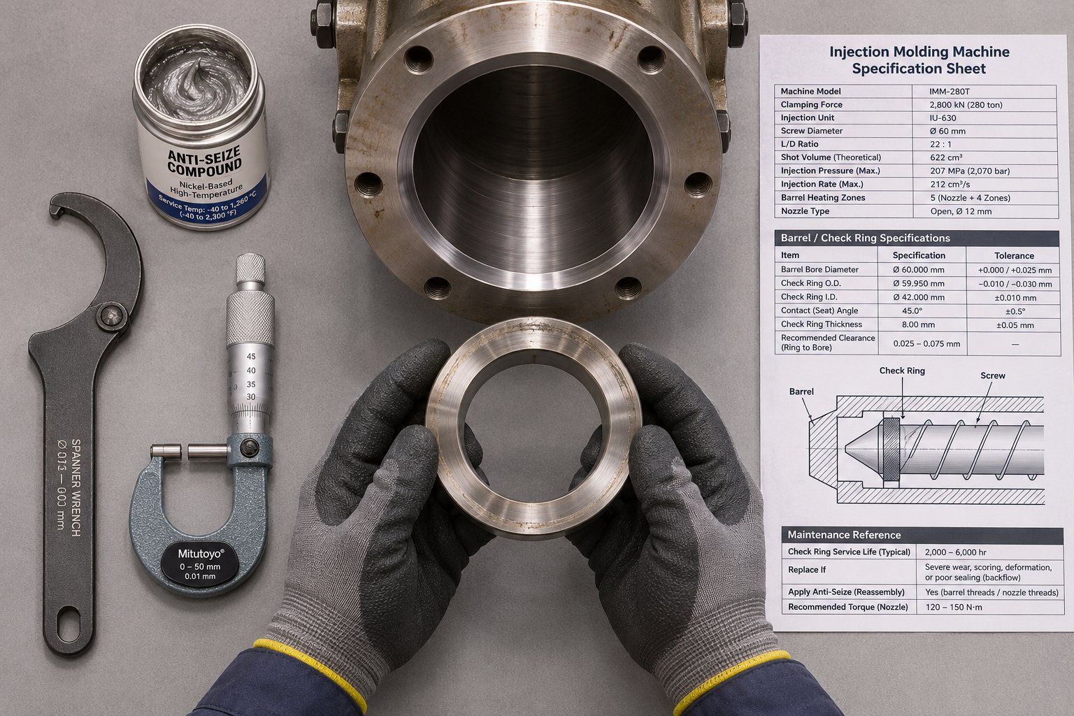
Gather correct tooling. You'll need a spanner wrench sized to the retainer or tip hex, a brass drift or soft-blow hammer for loosening seized components, heat-resistant gloves, and appropriate anti-seize compound for reassembly. Having the machine OEM manual nearby — with thread size, torque specification, and assembly diagram — eliminates guesswork when you're standing in front of a hot barrel.
Disassembly Sequence and Inspection Checkpoints
With the barrel hot, the screw retracted, hydraulics locked out, and tooling ready, follow this sequence. Each step includes an inspection checkpoint — don't skip these. The few minutes you spend evaluating each component while it's in your hand will save hours of troubleshooting later.
- Remove the nozzle tip and nozzle body. Unthread the nozzle tip first, then the nozzle body from the barrel head. If components resist, tap lightly with a brass hammer to break them free — loosen bolts partially (about two-thirds) and tap gently to allow any trapped gas to escape before fully removing. Clean residual resin from the nozzle bore while it's still hot by applying a release agent from the thread side to separate the material from the inner wall. Inspection checkpoint: examine the nozzle bore and nozzle tip seat for erosion, pitting, or resin buildup that could affect seating and flow in the next run.
- Slide or jog the screw forward until the screw tip assembly protrudes from the front of the barrel. On some machines, gravity alone won't bring the screw forward — you may need to briefly re-enable the hydraulic circuit to jog the screw ahead, then re-engage lockout before proceeding. Inspection checkpoint: as the screw emerges, look at the barrel bore condition near the front — scoring, discoloration, or embedded material on the bore wall suggest the check ring's OD has been wearing against it.
- Unthread the screw tip from the screw nose. Using the correct spanner wrench or hex fitting, break the tip free. As services for plastics screw tip assemblies specialists caution, never attempt to rotate or force a feedscrew without resin in the barrel — the metal-on-metal contact can score both the screw flights and the bore. If the tip resists, apply controlled heat directly to the tip body and tap with a brass drift rather than increasing wrench force to the point of thread damage. Inspection checkpoint: examine the threads on both the screw tip and the screw nose. Look for galling (material transfer between thread surfaces), stripped or rolled threads, and corrosion. Damaged threads here compromise concentricity when the assembly goes back together.
- Remove the check ring and retainer. Once the tip is unthreaded, slide the check ring off the tip body and remove the retainer from its engagement with the screw. On four-piece assemblies, the front seat will also come free at this stage. Keep components in order — laid out left to right in the sequence they came off — so reassembly orientation is obvious. Inspection checkpoint: this is the most critical evaluation stage. Measure the check ring's outer diameter and compare it to the barrel bore ID — any measurable reduction from the original specification indicates wear that affects sealing. Examine the ring's rear seating face and the retainer's mating surface for grooving, washout, or asymmetric wear patterns (which suggest concentricity problems from the thread interface). Check the tip nose profile for erosion, cracking from thermal fatigue, or material buildup in flow channels.
- Clean all components thoroughly. Use a brass brush and appropriate solvent or purge compound to remove all residual resin, carbon deposits, and anti-seize residue from threads, sealing surfaces, and flow passages. Avoid steel brushes or abrasive tools that can scratch precision-machined seating faces. Inspection checkpoint: with components fully cleaned, re-examine seating surfaces under good lighting. Wear that was invisible under a layer of carbonized resin often becomes obvious on a clean, dry surface.
Reassembly, Torque, and Verification
If inspection confirms that all components are within acceptable wear limits — or if you're installing a new replacement assembly — reassembly follows a careful reverse sequence with a few additional precautions that make the difference between a reliable seal and a premature callback.
Clean all threads and register surfaces. Even freshly inspected parts can carry debris from the cleaning process itself. Wipe threads on the screw nose and the tip body with a clean, lint-free cloth. Any grit trapped in the threads will embed under torque and accelerate galling the next time you need to remove the assembly.
Apply anti-seize compound on all threaded areas. This step is consistently emphasized in installation guidance because it serves a dual purpose: it prevents galling between dissimilar metals exposed to extreme thermal cycling, and it ensures you'll be able to remove the assembly at the next scheduled maintenance interval without resorting to destructive methods. Follow the machine OEM's recommendation for compound type — copper-based, nickel-based, or molybdenum-based anti-seize each have temperature ranges suited to different processing conditions.
Assemble components in the correct orientation. Place the retainer onto the screw nose first (or thread it on, depending on the design), then slide the check ring over the tip body, and finally hand-thread the tip into the screw nose. Make sure the register surface of the screw matches perfectly with the seat — misalignment here causes the exact concentricity problems that lead to crescent-shaped leakage paths and asymmetric ring wear. Hand-threading first verifies that the threads engage cleanly without cross-threading.
Tighten to proper torque. Once hand-tight, apply final torque using the spanner wrench. Over-torquing is a common and costly mistake — it can mushroom the register face, stretch threads beyond their elastic limit, and make future removal extremely difficult. Consult the machine instruction manual for the recommended torque value for your specific thread size and assembly configuration. If no specification is available, apply firm torque consistent with general industry practice for the thread diameter, erring on the conservative side. A properly applied anti-seize coat reduces the torque needed to achieve adequate clamping force.
Run post-assembly verification before releasing to production. Reassemble the nozzle body and nozzle tip, bring the barrel back up to operating temperature, and cycle the machine in semi-automatic mode. Run several short shots into a purge container or scrap mold, paying close attention to two indicators:
- Cushion stability: monitor the screw's final forward position over ten or more consecutive cycles. A consistent cushion — holding steady within a narrow range — confirms the check valve is sealing. Any progressive drift suggests the ring isn't seating properly and needs immediate re-inspection.
- Shot weight consistency: weigh consecutive short shots on a precision scale. Part-to-part weight variation should fall within your normal process capability. Significant spread indicates leakage past the newly installed assembly, which could point to incorrect orientation, a damaged seat that wasn't caught during inspection, or an incompatible replacement component.
Only after cushion and shot weight confirm a reliable seal should the machine be released for production parts. Skipping this verification step — or relying on a single shot to declare success — risks sending a poorly sealed assembly into a full production run where the first sign of trouble will be scrap in the finished-parts bin.
Even with a textbook installation, every screw tip assembly is a wear item operating under punishing conditions. The sealing surfaces that passed inspection today will gradually degrade over thousands of injection cycles, and the failure modes they develop along the way leave distinctive fingerprints on both the components and the molded parts. Recognizing those fingerprints early — before they escalate into chronic scrap — is where diagnostics and preventive maintenance intersect.
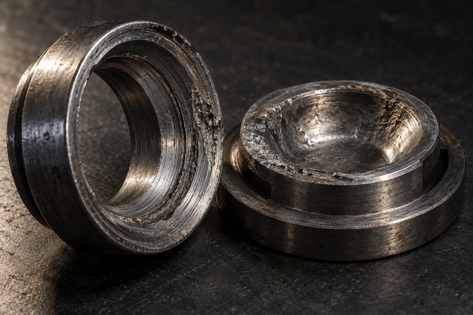
Screw Tip Assembly Failure Modes and Their Impact on Part Quality
A properly installed assembly with verified cushion stability and consistent shot weight is a great starting point — but it's not the end of the story. Every sealing surface inside that assembly is being ground down, washed out, or thermally stressed with each injection cycle. The degradation is slow, often invisible during routine production, and rarely announces itself with a single dramatic failure. Instead, it creeps in through gradually widening clearances, subtly eroding seat faces, and micro-cracks that propagate over thousands of thermal cycles.
The real danger isn't the failure itself — it's the gap between when wear begins affecting part quality and when someone on the floor actually notices. Bridging that gap requires understanding which screw tip assembly failure modes exist, what physical evidence they leave on the components, and — most critically — which molding defects each one produces. When you can look at a part defect and trace it back to a specific wear pattern inside the assembly, you stop chasing phantom process parameters and start solving the actual problem.
Wear-Related Failures — Ring Clearance, Seat Erosion, and Tip Cracking
Three primary failure mechanisms account for the vast majority of screw tip assembly wear indicators you'll encounter during inspection. Each one attacks a different sealing surface, progresses at a different rate depending on processing conditions, and leaves a distinct signature on both the component and the molded parts.
Check ring OD wear and barrel bore clearance growth. Every time the screw retracts during recovery, the check ring sits inside the barrel bore with melt flowing past it at elevated pressure and temperature. Abrasive resins — glass-filled nylon, mineral-filled polypropylene, carbon-fiber-reinforced compounds — accelerate this wear dramatically, but even unfilled commodity resins erode the ring's outer diameter over time. As the ring OD shrinks relative to the barrel bore ID, a growing annular gap forms between the ring and the barrel wall. During injection, melt escapes through this gap instead of being forced entirely into the mold. Barrel wear itself can compound this problem — as the bore enlarges from the inside out, even a ring that hasn't lost significant material may no longer seal effectively because the barrel it seats against has grown beyond specification.
Seat erosion between the check ring and retainer. The rear face of the check ring slams against the retainer's machined seat surface thousands of times per day, under pressures that can exceed 40,000 psi during thin-wall filling. Over time, this repeated high-pressure metal-to-metal contact washes out the seat — creating grooves, channels, or a dished profile that prevents full-face sealing. As industry documentation has noted, excessive wear on these seating areas can allow material to pass back over the valve, directly causing failure to hold cushion and poor quality consistency. The erosion pattern isn't always symmetrical, either. Concentricity problems from damaged threads or a mushroomed register face cause the ring to load unevenly against the seat, creating a crescent-shaped washout on one side while the opposite side barely contacts.
Tip cracking from thermal fatigue or improper torque. The screw tip (nose cone) endures enormous thermal cycling — heated to processing temperature during operation, cooled during shutdowns, then reheated at startup. Each cycle expands and contracts the metal, and over hundreds or thousands of these thermal events, micro-cracks can nucleate at stress concentration points such as thread roots, sharp internal radii, or surface imperfections from machining. Cracked rings and broken studs are frequently traced back to poor startup or shutdown procedures — failure to ensure the barrel reaches operating temperature before rotating the screw, or neglecting to purge properly before cooling down. Improper torque during installation — whether over-torqued to the point of thread stretching or under-torqued enough to allow micro-movement during cycling — accelerates crack propagation at the thread interface.
Thread galling and screw nose damage. This failure mode doesn't affect sealing directly, but it can make every other problem worse. Galling occurs when two metal surfaces weld together microscopically under high contact pressure and sliding motion — a common scenario when dissimilar metals (such as a hardened tool-steel tip threaded into a nitrided screw nose) are assembled without anti-seize compound and then subjected to extreme thermal cycling. When you attempt to unthread a galled assembly, the rotating force tears material from one surface and deposits it on the other, damaging threads on both the tip and the screw. The resulting thread damage compromises concentricity on reassembly and may even prevent proper thread engagement entirely, forcing a costly screw-nose repair or screw replacement.
How Each Failure Mode Maps to Molding Defects
Here's where the diagnostic value of understanding these failure modes becomes practical. Each type of wear produces specific, observable defects on molded parts. When you see a particular defect pattern emerge — especially one that resists process-parameter adjustments — cross-referencing it against this table points you toward the root cause far faster than trial-and-error troubleshooting.
| Failure Mode | Resulting Molding Defects |
|---|---|
| Check ring OD wear (ring-to-bore clearance growth) | Cushion drift cycle to cycle; short shots as melt volume leaks rearward during injection; inconsistent part weight; gradual loss of process repeatability that worsens over weeks |
| Seat erosion (ring-to-retainer sealing surface washout) | Backflow leakage during pack/hold phase; loss of effective packing pressure; sink marks and dimensional shrinkage in thick sections; reduced part density and mechanical strength |
| Material hang-up on a damaged or eroded tip | Resin stagnation and thermal degradation in dead zones; black specks and brown streaks in parts; burn marks from carbonized material breaking free and entering the melt stream; contamination in color-critical or optical applications |
| Cracked tip or broken stud | Air ingestion through the crack during decompression, causing splay (silver streaks); potential contamination from metal fragments entering the melt; catastrophic failure risk if the crack propagates to full fracture during injection |
| Thread galling on screw nose | Concentricity loss leading to asymmetric check-ring wear and uneven sealing; difficulty during future maintenance; potential for cross-threaded reassembly that compounds all other failure modes |
Notice the overlapping defect signatures. As plastics industry engineers have documented, many injection molding defects stem from mechanical wear rather than processing parameters — and worn screws, barrels, and check valves can introduce inconsistencies that lead to short shots, warping, sink marks, and other defects that cannot be corrected through machine settings alone. A short shot, for example, could originate from ring OD wear, seat erosion, or both simultaneously. Distinguishing between them requires pulling the assembly and physically inspecting the sealing surfaces — process data alone can tell you something is leaking, but it can't tell you which surface has failed.
Recognizing the Tipping Point for Replacement
Every check ring wears. Every seat surface erodes eventually. The practical question isn't whether degradation is occurring — it always is — but whether it has progressed far enough to justify pulling the screw and replacing the assembly. Swap too early, and you waste money on components that still had useful life. Wait too long, and you pay the price in scrap, machine downtime, and customer complaints.
Several general criteria help identify when check ring wear in injection molding has crossed the line from acceptable to actionable:
- Cushion variation exceeds the process window. If your validated process requires a cushion of, say, 10 mm +/- 0.5 mm and you're seeing swings of 1.5 mm or more across consecutive cycles — despite stable hydraulic or servo performance — the check valve is likely leaking enough to steal meaningful shot volume. This is the earliest and most reliable screw tip assembly wear indicator available from the operator's station.
- Scrap rate trends upward despite parameter adjustments. A technician bumps injection pressure up a notch to compensate for slightly short parts. A week later, flash appears on a different edge, so hold pressure comes down. Two weeks after that, sink marks show up in a thick section. This escalating cycle of compensating adjustments — each one masking the true root cause — is a hallmark of progressive valve wear. The part defects aren't a process problem; they're a mechanical-seal problem that no amount of parameter tuning will fix permanently.
- Physical inspection reveals measurable clearance beyond design specification. When you pull the assembly and measure the check ring OD against the known barrel bore diameter, any reduction from the original ring dimension represents lost sealing capability. Similarly, visible grooving on the retainer seat, a dished contact face on the check ring, or a measurable gap between mating surfaces when you press the ring against the seat by hand all indicate wear beyond the design intent. Reference your machine OEM documentation for specific dimensional tolerances — these vary by barrel size, valve design, and manufacturer. If OEM tolerances aren't available, compare measurements to a new or known-good spare assembly as a baseline.
- The screw turns during injection. This is a particularly telling indicator: if you observe the screw rotating during the injection stroke, it's a strong sign that the non-return valve is leaking badly enough that melt flowing backward over the flights is spinning the screw. At this point, the assembly is well past its useful service life and should be replaced immediately.
One last consideration: don't evaluate wear in isolation. A check ring that measures slightly below nominal might still seal adequately in a barrel bore that's also at nominal. But if both the ring and the bore have worn — the ring shrinking while the bore enlarges — the combined clearance can be double what either measurement alone would suggest. Always assess the ring-to-bore relationship as a system, not as individual components.
Knowing what failure looks like on disassembled components is valuable, but most of the time your first clue won't come from an inspection bench. It will come from what you see — or what operators report — happening to the parts rolling off the production line. Connecting those floor-level symptoms back to their mechanical root cause inside the assembly is where effective troubleshooting begins.
Symptom-Based Troubleshooting for Screw Tip Assembly Problems
Failure-mode tables and inspection measurements are powerful — when the screw is already out of the barrel and laid on a bench. But that's rarely where the story starts. On a running production floor, nobody pulls a screw on a hunch. Something has to go wrong first: a part comes out light, a streak shows up on a cosmetic surface, or the cushion position starts wandering on the controller screen. The defect comes before the diagnosis, every time.
That reality calls for a troubleshooting approach that begins with what you actually observe — the symptom — and works backward to the mechanical cause inside the assembly. Instead of asking "what does ring wear look like?" ask "why are my parts suddenly short?" Flipping the diagnostic direction this way matches how screw tip assembly troubleshooting actually happens on the floor, and it gets you to the root cause faster.
Cushion Drift and Inconsistent Shot Weight
Imagine watching your cushion position on the controller over a dozen cycles. It should hover within a tight band — maybe a few tenths of a millimeter from shot to shot. Instead, you notice it creeping: 10.2 mm on one cycle, 9.6 mm the next, then 10.8 mm, then 9.1 mm. The set points haven't changed. The hydraulic pressures look normal. But the cushion won't sit still.
A wandering cushion is the most common early indicator of check-ring wear or seat degradation inside the screw tip assembly. What's happening mechanically is straightforward: during injection, melt is leaking backward past a compromised seal instead of traveling entirely into the mold. The screw pushes the same stroke, but a variable amount of material escapes rearward each cycle, and the cushion position reflects that inconsistency. As injection molding process analysts have noted, when cushion variation and part weight begin changing together, the injection unit — and specifically the check ring — deserves a closer look.
Here's a useful distinction: cushion drift caused by a screw tip assembly typically worsens gradually over weeks or months, tracking the slow progression of ring or seat wear. Hydraulic valve drift or servo repeatability issues, by contrast, tend to appear more suddenly — often after a maintenance event or following a period of machine inactivity — and they affect other machine movements (clamp stroke, ejection) as well. If the cushion is wandering but clamp and ejector functions look crisp and repeatable, the check valve moves to the top of the suspect list.
Inconsistent shot weight follows the same pattern. Weighing consecutive parts on a precision scale and plotting the results over time reveals a widening spread that mirrors the cushion instability. Parts that once held within a milligram or two of each other start showing random variation that no amount of pack-pressure tweaking can correct — because the problem isn't the pressure setting, it's the seal that's supposed to hold that pressure.
Black Specks, Splay, and Discoloration
Black specks on injection molded parts trigger an immediate reaction on most production floors — and the first assumption is usually contamination. Someone checks the hopper for foreign material, inspects the regrind bin, or questions the resin lot. Those are reasonable steps, but they skip a common culprit sitting at the very front of the screw.
When the screw tip's nose cone is eroded, cracked, or has rough surface features from wear, molten resin can stagnate in the resulting dead zones. Material trapped in these pockets doesn't flow forward with the bulk melt — it sits, overheats, and degrades into carbonized residue. As polymer processing specialists have documented, screw tips and damaged check valves are a recognized source of black specks in injection molding, because their damaged surfaces create the hang-up zones where resin breaks down into carbon residues. Eventually, a fragment of this degraded material breaks loose, gets swept into the melt stream, and embeds in a molded part as a dark speck or streak.
Splay — those silvery streaks radiating outward from the gate — is a different symptom with a different mechanism but a related root cause. When a cracked tip or worn check ring allows air to be drawn into the melt pool during decompression (suck-back), that trapped air expands as it enters the hot mold cavity, creating the characteristic streaks on the part surface. The defect mimics moisture-related splay almost perfectly, which is why technicians often chase dryer settings and dew-point readings for days before considering that the problem might be a mechanical seal failure rather than a material-handling issue.
Discoloration — yellowing, browning, or an overall shift in color intensity — follows the same degradation logic as black specks but at an earlier, less visible stage. Resin spending too much time at elevated temperature inside a damaged tip assembly begins to discolor before it fully carbonizes. If you're molding natural or light-colored parts and notice a gradual tint shift that doesn't correlate with any material or temperature change, the flow path through the assembly warrants inspection.
Short Shots and Flash on the Same Mold
Here's a scenario that frustrates even experienced technicians. A mold that's been running reliably for months starts producing short shots — cavities not filling completely, thin-wall sections coming up empty. The natural response is to bump injection pressure or increase shot size. That fixes the short shots, but now flash appears along the parting line or around ejector pins. Lower the pressure to control the flash, and the shorts come back. As injection molding troubleshooting resources confirm, a leaking check valve is a common mechanical cause of short shots that survives every process change — and it can create the contradictory condition of both short shots and flash from the same mold.
When a mold that previously ran well begins producing both short shots and flash simultaneously, the screw tip assembly should be the first suspect — not the last.
The paradox makes mechanical sense once you trace the flow. A worn check valve leaks melt rearward during injection, robbing the cavity of material and causing a short shot. The technician compensates by raising injection pressure or adding shot size. Those higher pressures push more melt past the flash line of the mold — which was never the problem — while the rearward leakage continues unabated. You end up fighting two defects that share a single root cause: a seal that no longer holds.
The distinguishing clue is timing. If short shots and flash appear together on a mold that previously produced good parts without either defect, and if the onset was gradual rather than sudden, the evidence points firmly toward progressive check-valve degradation rather than a tooling or process issue.
Quick-Reference Symptom Checklist
Use the following list as a floor-level diagnostic starting point. When any of these symptoms appear — especially in combination — pull the screw tip assembly inspection forward on your maintenance schedule rather than continuing to adjust process parameters:
- Cushion position wandering more than the established baseline range over consecutive cycles
- Part weight variation increasing gradually over days or weeks without any process, material, or mold change
- Short shots and flash occurring simultaneously on a previously stable mold
- Black specks or brown streaks that persist after verifying clean material, purging the barrel, and ruling out hot-runner contamination
- Splay or silver streaks that do not respond to drying adjustments or moisture-reduction measures
- Color shift or discoloration on natural or light-colored parts with no change in resin lot or temperature settings
- Screw rotating during injection stroke — visible on the controller or through physical observation — indicating severe backflow past the check valve
- Progressive increase in required injection pressure to maintain the same fill pattern, suggesting the process is compensating for rearward leakage
Each of these symptoms can have other causes — hydraulic issues, material variation, mold wear — but when two or more appear together and conventional adjustments fail to resolve them, the assembly at the front of the screw deserves priority attention. Diagnosing the problem is the critical first step; the next consideration is acting on that diagnosis — figuring out where to source the right replacement, what information to gather before requesting a quote, and how to build a spare-parts strategy that keeps your critical machines running.
Sourcing and Replacing Screw Tip Assemblies
A confirmed diagnosis — measurable ring wear, eroded seat surfaces, or a cracked tip — puts you at a decision point. The assembly needs to come out, and a replacement needs to go in. The speed and accuracy of that swap depend less on wrench work (you've already got the procedure) and more on how well you've prepared the sourcing side: knowing what to order, where to get it, and whether the replacement will actually match your machine.
Get this wrong, and you trade one problem for another — a dimensionally incorrect assembly that technically fits the threads but doesn't seal properly, or a lead-time surprise that stretches a planned two-hour maintenance window into a week of unplanned downtime.
OEM Versus Aftermarket Replacement Options
The first fork in the road is whether to source a replacement screw tip assembly from the original equipment manufacturer or from an aftermarket supplier. Each path carries distinct trade-offs.
OEM replacements guarantee dimensional compatibility with your specific machine. The thread pitch, seat angle, ring OD tolerance, and retainer geometry will match the original engineering drawings because they come from the same source. The downsides? OEM screw tip assembly replacement often involves longer lead times — sometimes weeks, especially for less common models — and higher unit costs. If your machine is an older model or a brand with limited North American support, OEM availability can be even more constrained.
Aftermarket and custom-manufactured alternatives can match OEM specifications precisely, provided the supplier has a rigorous dimensional verification process. The best aftermarket screw tip assemblies aren't generic approximations — they're reverse-engineered from original drawings, worn samples, or detailed measurements taken directly from the machine. Pricing is typically lower, and turnaround can be faster, particularly from suppliers that maintain extensive CAD libraries across multiple machine brands. As aftermarket specialists have demonstrated, suppliers with libraries covering thousands of prints for tips, barrels, and related components can manufacture assemblies to match virtually any machine configuration — and they consistently advise molders to save original assemblies as dimensional references for future orders.
Machine-specific assemblies add a layer of complexity regardless of which route you choose. Engel, Demag, Battenfeld, Cincinnati, and Nissei machines each use proprietary barrel bores, thread specifications, and valve geometries. A replacement that matches bore diameter but misses the thread pitch by half a millimeter or uses the wrong seat taper angle won't seal — period. Precise cross-referencing against your machine's documentation or the original worn assembly is non-negotiable.
What to Prepare Before Requesting a Quote
Whether you're contacting an OEM parts desk or an aftermarket manufacturer, the quality and speed of the quoting process depend entirely on the information you provide upfront. Vague requests like "I need a screw tip for an Engel" generate vague responses and risk receiving the wrong part. Gather the following before making the call:
- Machine make, model, and year — including the injection unit designation if the machine offers multiple configurations
- Barrel diameter (bore ID) and screw diameter — measured, not assumed from the machine nameplate, since wear may have altered original dimensions
- Existing screw tip dimensions or engineering drawings — if your maintenance files include the original assembly print, this is the single most valuable piece of information you can provide
- Photographs of the worn assembly — clear images of the tip, check ring, retainer, and thread interface give the supplier visual context for wear patterns and design configuration
- Material being processed — resin type and filler content influence the alloy recommendation for the replacement; a shop running 30% glass-filled nylon needs a very different metallurgy than one molding unfilled polypropylene
One supplier that exemplifies this consultative approach is NANHAIYA, which manufactures replacement screw tips, check rings, non-return valves, and related injection molding components. Before quoting, their team reviews machine details, engineering drawings, worn samples, photos, and critical dimensions to assess part compatibility and manufacturing feasibility — essentially walking through the same preparation checklist outlined above. This verify-first workflow reduces the risk of dimensional mismatches and ensures the replacement assembly drops into your barrel with the correct thread engagement, seat geometry, and ring clearance. It's a practical example of how aftermarket sourcing works when the supplier treats dimensional verification as a prerequisite, not an afterthought.
Building a Spare-Parts Strategy
Sourcing a replacement after failure is reactive. Building a spare-parts strategy before failure is where real uptime protection begins.
For critical machines — the ones running your highest-volume jobs, your tightest-tolerance parts, or your longest-lead-time molds — keeping a measured spare assembly on the shelf eliminates the gap between diagnosis and action. When inspection confirms wear has crossed the replacement threshold, the spare goes in immediately, and the worn assembly ships out for remanufacture or serves as the dimensional reference for ordering the next spare. The machine never waits on a purchase order.
This approach aligns with spare parts inventory management best practices used across equipment-intensive industries: categorize parts by criticality and consumption value, stock vital spares for high-risk assets, and track lead times so reorders happen before safety stock runs out. A screw tip assembly for a machine running 24/7 on a single-source automotive contract clearly falls into the "vital" category — the cost of stocking one spare is trivial compared to the cost of a production shutdown waiting for delivery.
Whether you source through an OEM channel or an aftermarket manufacturer like NANHAIYA, evaluate replacement screw tip assemblies and the services behind them against three criteria:
- Dimensional verification process: Does the supplier confirm compatibility against drawings, samples, or machine documentation before manufacturing — or do they ship based on a part number alone?
- Material certification: Can the supplier provide documentation of the tool steel grade, hardness, and heat treatment used in the assembly? For abrasive-resin applications, this certification is the difference between a long-lived replacement and a premature re-order.
- Turnaround time: Understand standard and expedited lead times for both stock and custom-manufactured assemblies. A supplier with an extensive library of existing prints and ready-to-ship inventory for common machine brands will get you back into production faster than one starting from scratch.
The goal isn't just to buy a part — it's to build a repeatable supply chain for a component that will wear out again. Every assembly you install today is tomorrow's replacement candidate. Having the sourcing relationship, dimensional records, and shelf inventory already in place turns an inevitable wear event from an emergency into a scheduled maintenance task — and that shift, more than any single component upgrade, is what keeps your machines producing good parts instead of scrap.
Frequently Asked Questions About Screw Tip Assemblies
1. What are the signs that a screw tip assembly needs to be replaced?
The most reliable early warning sign is cushion position drift — when the screw's final forward position varies noticeably from cycle to cycle despite stable machine settings. Other key indicators include gradually increasing part weight variation, simultaneous short shots and flash on a previously stable mold, persistent black specks that survive purging, splay that does not respond to drying adjustments, and the screw visibly rotating during the injection stroke. When two or more of these symptoms appear together and standard process adjustments fail to resolve them, physical inspection of the check ring, retainer seat, and tip nose should be prioritized. Measurable clearance growth between the check ring OD and the barrel bore, visible grooving on the retainer seating surface, or cracking on the tip body all confirm the assembly has exceeded its useful service life.
2. What is the difference between a sliding ring check valve and a ball check valve in a screw tip assembly?
A sliding ring check valve uses a free-floating ring that slides axially along the tip body — forward during plasticization to allow melt flow, and rearward during injection to seat against the retainer and block backflow. Because the ring does not rotate with the screw, it causes minimal barrel bore wear and is the most widely used design across all barrel sizes. A ball check valve replaces the ring with a sphere that seats into a tapered pocket to seal the flow path. Ball checks are more compact, making them ideal for small-diameter barrels such as 13 mm or 18 mm units where radial space is limited. They also offer faster shut-off for low-viscosity resins. However, their sealing outer diameter rotates with the screw, which can accelerate barrel bore wear over extended production runs. Sliding rings are the general-purpose standard; ball checks fill a niche where barrel geometry or resin viscosity demands a more compact, faster-seating valve.
3. How does a worn screw tip assembly affect injection molded part quality?
A degraded screw tip assembly disrupts the seal that keeps molten resin moving forward into the mold during injection. When the check ring or retainer seat wears, melt leaks backward over the screw flights instead of filling the cavity completely. This backflow causes cushion drift, inconsistent shot volume, and unpredictable part weights. Specific defect patterns include short shots from lost melt volume, sink marks from inadequate packing pressure, flash from compensatory pressure increases, black specks from resin stagnating in eroded tip surfaces, and splay from air ingested through cracks during decompression. Because wear progresses gradually, these defects often appear subtly at first and worsen over weeks, leading technicians to chase process parameter adjustments that never address the true mechanical root cause.
4. How often should a screw tip assembly be inspected or replaced?
There is no universal replacement interval because wear rates depend heavily on the resin being processed, filler content, injection pressures, cycle frequency, and the alloy grade of the assembly components. Abrasive glass-filled or mineral-filled resins can wear sealing surfaces in a fraction of the time that unfilled commodity resins would. Rather than relying on a fixed schedule, the most effective approach is condition-based monitoring: track cushion stability and part weight trends continuously, and schedule a physical inspection whenever these metrics begin drifting outside established baselines. Many facilities incorporate a screw pull and tip assembly inspection into quarterly or semi-annual preventive maintenance routines for high-utilization machines, adjusting frequency based on observed wear progression. Keeping a measured spare assembly on the shelf for critical machines ensures immediate replacement when inspection confirms wear beyond acceptable limits.
5. What information do I need to source the correct replacement screw tip assembly?
Accurate sourcing requires five key pieces of information: the machine make, model, and year (including injection unit designation); the measured barrel bore diameter and screw diameter; original engineering drawings or dimensional records for the existing assembly; clear photographs of the worn tip, check ring, retainer, and thread interface; and the resin type and filler content being processed, which influences alloy selection. Suppliers like NANHAIYA review these details — drawings, worn samples, photos, and critical dimensions — to verify part compatibility and manufacturing feasibility before quoting. This consultative verification process is especially important for machine-specific assemblies from brands like Engel, Demag, Battenfeld, Cincinnati, and Nissei, where proprietary thread pitches, seat taper angles, and ring tolerances vary between manufacturers and even between model series.
Written by
Nanhaiya Technical Team
Zhoushan Nanhaiya Plastic Machinery Co., Ltd.
The Nanhaiya technical team supports screw and barrel manufacturing projects through application review, technical communication, custom manufacturing coordination, and production and quality control.
Discuss Your Application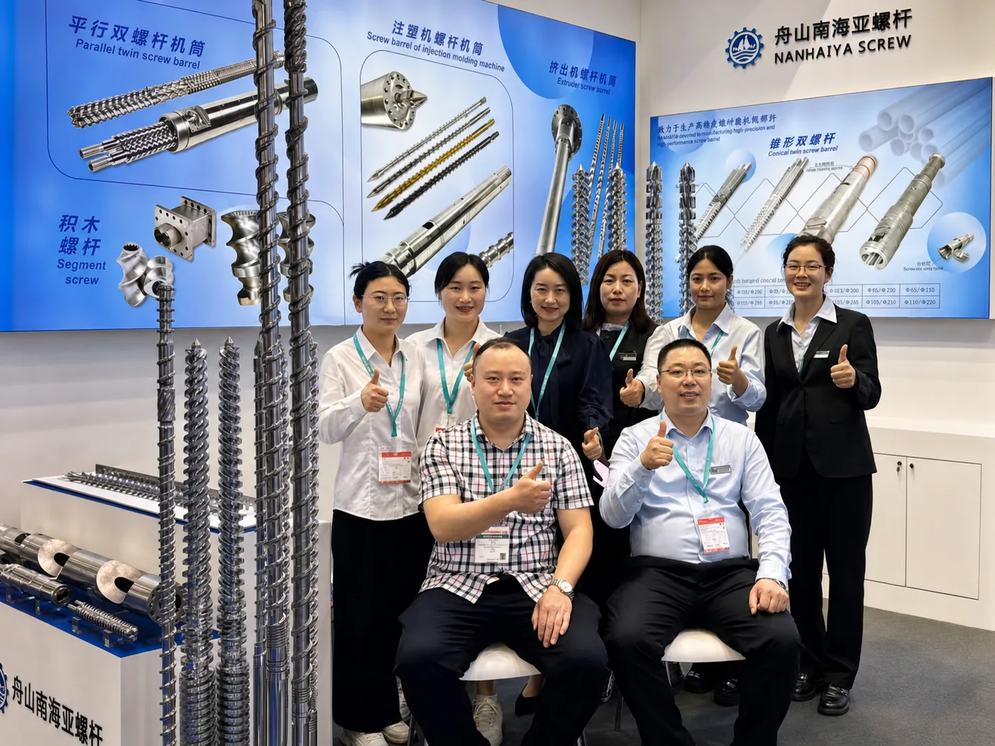
Related Articles
More insights on screw barrel technology and plastics processing.
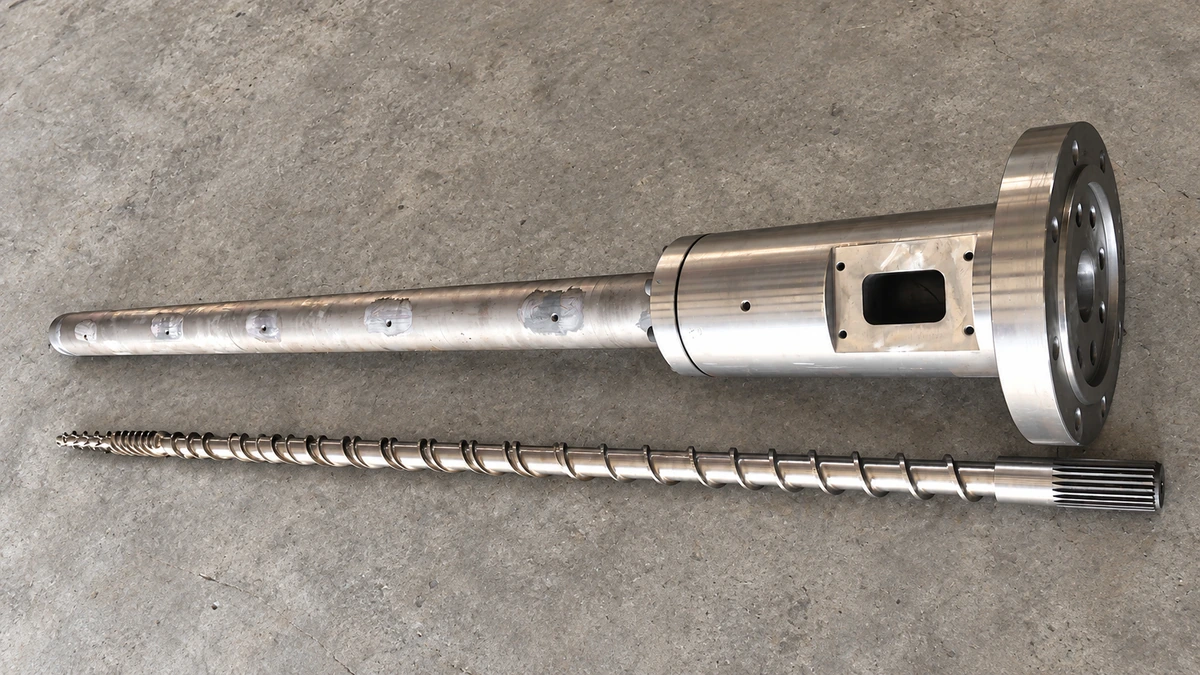
Why Your Single Screw Extruder Design Causes Extrusion Defects
Nov 13, 2026
Learn how single screw extruder design parameters—L/D ratio, compression ratio, channel depth, and mixing elements—affect melt quality, throughput, and defects.
Read Article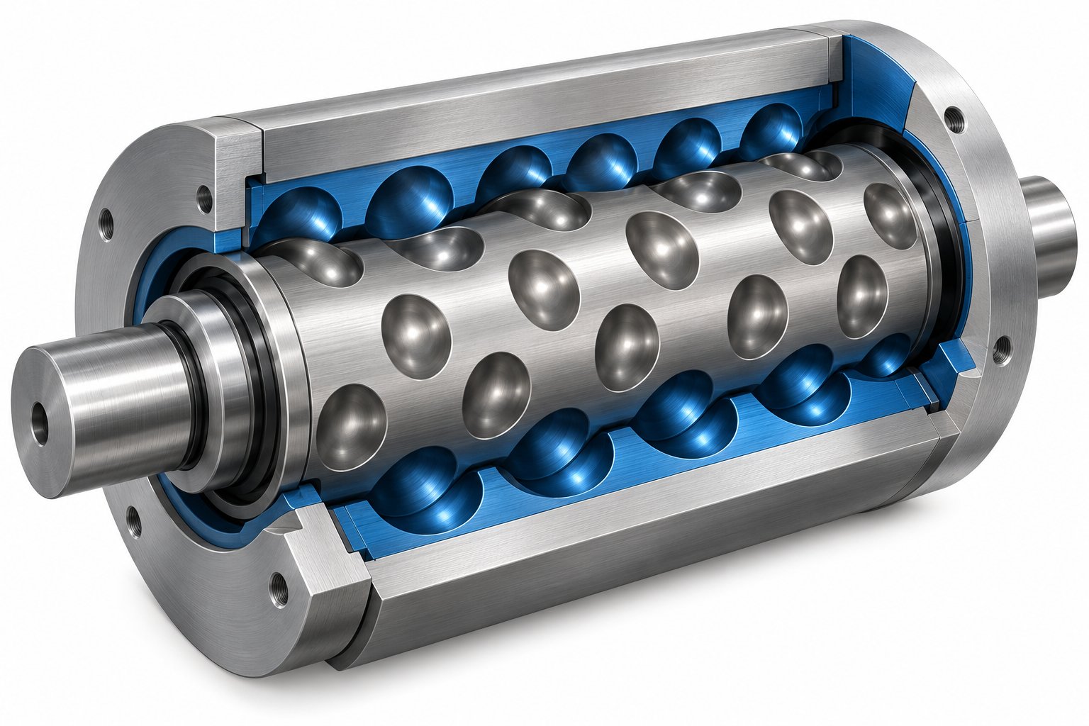
Cavity Transfer Mixer: The Blender Your Extruder Didn't Know It Needed
Nov 13, 2026
Learn how a cavity transfer mixer (CTM) upgrades single-screw extruder mixing. Covers working principles, key parameters, integration, applications, and comparisons.
Read Article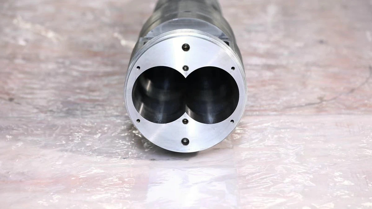
Extruder Barrel Alignment Decoded: Tolerances Most Plants Miss
Nov 13, 2026
Learn extruder barrel alignment tolerances, laser procedures, thermal offsets, and proactive schedules most plants miss — for single-screw and twin-screw lines.
Read ArticleLooking for something else?
Search by material, symptom or product and jump straight to the relevant page.
These are navigation suggestions based on keyword matching — not a quotation, not a delivery commitment, and not a substitute for engineering review. Final specification is confirmed by our engineers against your drawings and processed material.
Need help with screw barrel selection?
Share your machine model, processed material and application. Our team can help with pricing and technical support.