

What Silver Streaks Really Are and Why They Signal Deeper Problems
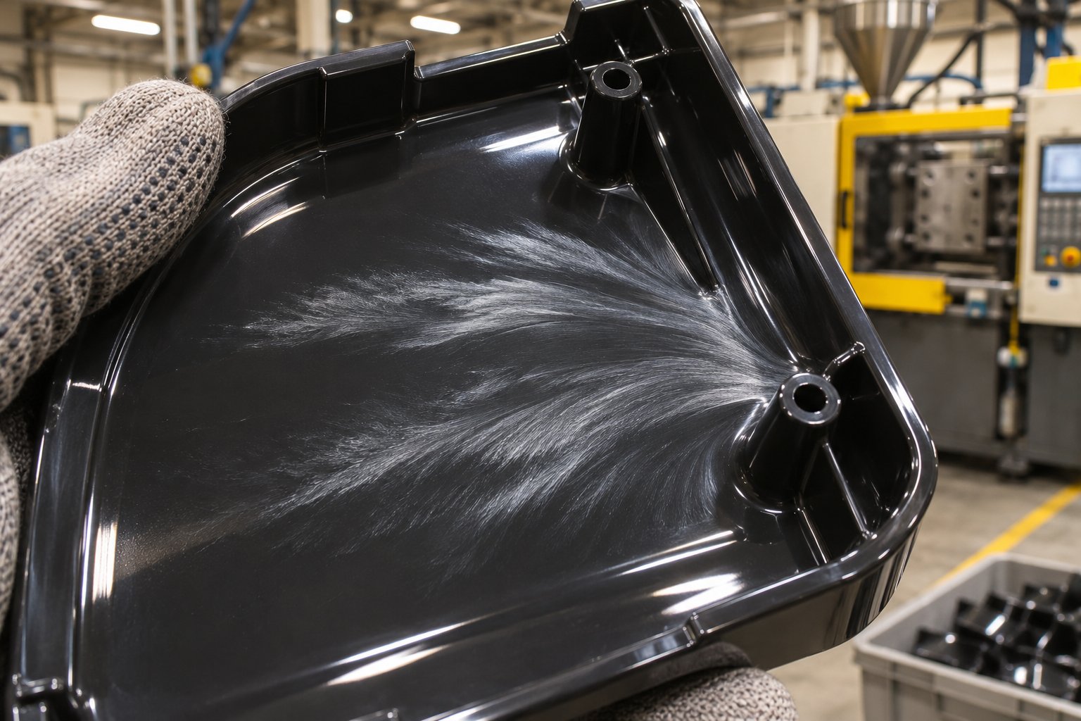
Silver streaks in injection molding — also called splay marks — are elongated, silvery, finger-like lines that appear on the surface of a molded part, oriented in the direction of melt flow. They look like fine, shimmering scratches fanning outward from the gate or along the flow path, and they immediately signal that something went wrong inside the melt before it reached the cavity wall. Every molder encounters them. Few stop to ask what they actually reveal about the process happening behind the mold steel.
Defining Silver Streaks and Splay Marks
The terms "silver streaks" and "splay marks" describe the exact same defect. You'll hear both on the shop floor and in technical literature — sometimes even "splash marks" in older references. Regardless of the label, the defect presents as bright, hair-like stripes extending along the melt filling direction. In severe cases, the streaks merge into large areas of surface whitening or a cloudy, washed-out appearance that ruins part aesthetics. The key visual signature is directionality: the marks always follow the flow path of the polymer melt, distinguishing them from other cosmetic defects like flow marks or burn marks.
How Silver Streaks Actually Form Inside the Melt
Imagine molten polymer flowing through a runner and into the cavity. Under normal conditions, that melt is a continuous, homogeneous stream. But when a volatile substance is present — water vapor, a gas released by thermal degradation, or a pocket of trapped air — tiny bubbles nucleate inside the melt. These bubbles don't just float in place. The advancing melt front drags them forward along the flow path, stretching them into elongated voids.
Here's where the surface defect is born. As the melt contacts the cooler cavity wall and begins to solidify, those stretched gas pockets get pinned near the surface. The thin skin of polymer over each bubble ruptures or collapses, leaving a shallow, elongated groove. Light reflects off these disrupted surface areas differently than the surrounding smooth plastic — and you see the characteristic silvery streak.
The volatile source determines the streak's behavior. Water vapor from poorly dried hygroscopic resin tends to produce fine, evenly distributed streaks. Gases from thermal degradation often carry a brownish tint and appear more randomly. Trapped air pockets may cause intermittent streaks concentrated at the end of fill or near weld lines. But the fundamental mechanism — bubble nucleation, elongation by flow, and surface rupture — remains the same across every type of injection molding silver streak.
Why Silver Streaks Matter Beyond Cosmetics
It's tempting to treat splay as a purely visual problem. After all, the part still fills, still ejects, still looks roughly correct at arm's length. But those ruptured bubble sites are weak points. Impact strength near splay regions drops because the surface layer is disrupted and riddled with micro-voids. Customer rejects climb. And here's the part that often gets overlooked: the volatile source causing the streaks may also be degrading properties you can't see — molecular weight loss from thermal degradation, hydrolysis weakening the polymer backbone, or contamination quietly compromising batch after batch.
A part that shows splay on the surface is telling you that gas was present in the melt. If that gas came from material degradation, the same degradation is reducing tensile strength, elongation, and chemical resistance throughout the entire cross-section — not just where the streaks are visible. Ignoring the symptom means accepting a hidden decline in part performance and an unpredictable spike in scrap rates.
Silver streaks are a symptom, not a disease. The real work is identifying which volatile source — moisture, thermal degradation, shear, trapped air, or contamination — is responsible. Fix the source, and the streaks disappear. Chase only the streaks, and you'll spend hours adjusting parameters without solving the underlying problem.
That distinction between symptom and source is exactly why learning how to avoid silver streaks in injection molding requires more than a single checklist. It demands a structured approach to diagnosis — one that separates moisture-driven splay from shear-driven splay from degradation-driven splay, because each demands a fundamentally different corrective action.
Five Types of Silver Streaks and How to Tell Them Apart
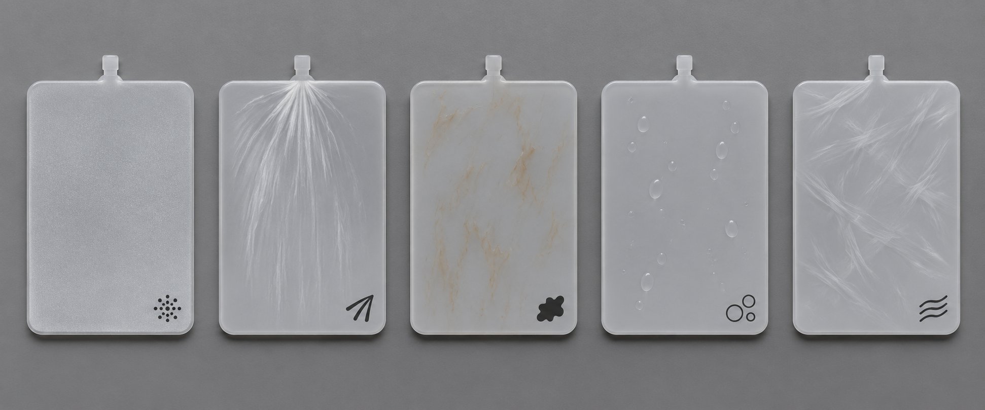
Separating the volatile source from the visible symptom starts with one skill: reading the streaks themselves. Every silver streak defect in injection molding carries visual fingerprints — location on the part, density, color tint, surface texture — that point toward a specific root cause. The trouble is, most troubleshooting guides lump all splay into a single bucket and jump straight to "dry your material." That works when moisture is the culprit. It wastes hours when it isn't.
Five distinct splay types appear in production. Each one looks different, shows up in a different zone of the part, and responds to a different corrective action. Once you can identify which type you're looking at, you've already eliminated most of the guesswork.
Moisture Splay vs. Shear Splay — Visual Differences
Moisture splay is the most common cause of silver streaks in injection molding, and it has a distinctive appearance. Picture fine, U-shaped or fan-like streaks radiating outward from the gate area, spread relatively evenly across the part surface. The marks have a dull, hazy, matte quality — almost like a thin fog was dragged across the plastic. In severe cases, the streaks are so dense they merge into a large cloudy region, and you'll notice the surface feels slightly rougher to the touch. The key giveaway is uniformity: moisture splay doesn't favor one side of the part over the other. It distributes along the entire flow path because the water vapor is dispersed throughout the melt from the moment it leaves the barrel.
Shear splay looks different. You'll find it concentrated near the gate or at sharp geometry transitions — thin-wall sections, corners, rib intersections — anywhere the melt is forced through a restriction at high velocity. The streaks tend to be coarser, more defined, and more localized than moisture splay. They may appear as bright, glossy lines rather than the matte haze of moisture-driven marks. Here's a useful mental shortcut: if the splay is worst right at the gate and fades as you move toward the end of fill, shear is your primary suspect. Moisture splay, by contrast, doesn't fade with distance — it persists wherever the melt front traveled.
Another telling detail is repeatability. Shear splay reappears in the same location, shot after shot, because it's tied to a fixed geometric restriction. Moisture splay can shift slightly between shots as moisture content fluctuates, and it tends to worsen progressively if the dryer isn't keeping up.
Heat Splay, Air Splay, and Contamination Splay Identification
Heat splay — also called thermal degradation splay — carries a visual signature that separates it immediately from the moisture variety. Look for streaks with a brownish or yellowish tint, especially visible in light-colored resins. The marks often appear irregular and comet-like rather than following a clean fan pattern. You'll frequently notice darkening along the sprue or in the runner system as well, which is a strong indicator that the polymer is breaking down before it even reaches the cavity. As FirstMold's practical guide notes, thermal silver streaks don't follow a specific pattern the way moisture splay does — they can appear randomly and are sometimes accompanied by a burnt or acrid odor from the purge.
Air splay — sometimes called decompression splay — tends to show up as intermittent, bubble-like marks or spray-pattern streaks. You'll often see them on the first few shots after startup and then watch them vanish once the process stabilizes and residual air is purged. When air splay persists during steady-state production, it typically concentrates at the last areas to fill, near weld lines, or in deep rib and boss features where gas has no escape route. The streaks may look slightly raised or bubbly compared to the flat, smeared appearance of moisture splay. A strong clue: if the splay disappears when you increase back pressure moderately, trapped air was likely the driver.
Contamination splay is the wildcard. It can mimic almost any other type, but it usually shows random, inconsistent distribution that doesn't correlate neatly with gate location or fill pattern. You might see color-shifted streaks if a foreign resin or incompatible masterbatch is decomposing in the melt. Black specks or dark streaks mixed in with the silver marks point toward degraded material from a previous run, a dirty barrel, or contaminated regrind. The randomness is the diagnostic clue — contamination doesn't follow the physics of flow path and gate geometry the way the other four types do.
To pull all five types together into a single diagnostic reference, the table below maps each splay variety against its visual characteristics, typical part location, root cause, and the first corrective step to try.
| Type | Appearance Description | Typical Location on Part | Primary Root Cause | First Corrective Action |
|---|---|---|---|---|
| Moisture Splay | Fine, dense, U-shaped or fan-like streaks with a dull, matte, hazy surface quality; evenly distributed | Widespread from gate through end of fill; uniform across the part surface | Absorbed or surface moisture flashing to steam in the barrel | Verify pellet moisture content with analyzer; dry material to resin-specific datasheet spec using a desiccant dryer |
| Shear Splay | Coarser, more defined streaks; often glossy rather than matte; concentrated rather than widespread | Near the gate, at thin-wall sections, sharp corners, or geometry transitions | Excessive shear stress mechanically degrading polymer chains and generating volatiles | Reduce injection speed (especially the first-stage velocity through the gate); evaluate gate size |
| Heat / Degradation Splay | Irregular, comet-like streaks with brownish or yellowish tint; may accompany darkened sprue or runner material | Random distribution; often visible in sprue area first; can appear anywhere on the part | Excessive melt temperature, prolonged residence time, or hot-runner overheating breaking polymer chains | Lower metering-zone barrel temperature in 10-15 °C increments; check thermocouple calibration and residence time |
| Air / Decompression Splay | Intermittent, bubble-like or spray-pattern marks; may appear slightly raised; often worst on first shots | End-of-fill regions, near weld lines, deep ribs and bosses, or areas with poor venting | Trapped air from excessive suck-back, low back pressure, poor venting, or nozzle-seat air leaks | Reduce screw decompression (suck-back) distance; increase back pressure moderately; inspect vent condition |
| Contamination Splay | Random, inconsistent streaks; may include color shifts, black specks, or dark streaks mixed with silvery marks | No consistent correlation with gate location or fill pattern; random distribution across parts | Foreign resin, incompatible masterbatch, degraded regrind, or residual material from previous production runs | Purge barrel thoroughly; inspect regrind for contamination; verify masterbatch compatibility with base resin |
Bookmark or print that table. It works as a quick-reference diagnostic tool at the press — examine the part, match the visual pattern to a splay type, and you immediately know which corrective direction to pursue first. The goal isn't to memorize every nuance but to narrow five possible causes down to one or two within minutes of spotting the defect.
Of course, visual identification gives you a strong hypothesis, not a confirmed diagnosis. Some cases overlap — a part might show moisture splay across the surface and shear splay concentrated at the gate simultaneously. That's where a structured elimination workflow becomes essential, walking you through targeted tests that isolate the actual volatile source step by step.
A Diagnostic Decision Tree to Isolate the Root Cause
Identifying the splay type by appearance is a strong starting point, but visual clues alone won't always give you a definitive answer — especially when two volatile sources overlap. What separates an experienced process technician from someone guessing at parameters is a repeatable elimination sequence: a series of targeted tests, each one designed to confirm or rule out a specific cause before moving to the next. This diagnostic-first approach to silver streaks in plastic injection molding saves hours of blind trial-and-error adjustment, and it works regardless of the resin, machine, or mold you're running.
Think of it like a doctor ruling out conditions one at a time rather than prescribing every medication at once. You change one variable, observe the result, and let the evidence guide your next move.
Step-by-Step Elimination Workflow
The sequence below mirrors how a seasoned technician actually works through a silver streak injection molding problem on the shop floor. Each step either confirms a root cause — letting you stop and fix it — or eliminates that cause and narrows your focus to the next most likely suspect.
- Check material moisture with a moisture analyzer. Pull a sample of pellets directly from the feed throat — not from the dryer hopper, where conditions may differ from what's actually entering the barrel. Measure the residual moisture content against the resin manufacturer's maximum allowable threshold (typically below 0.02% for hygroscopic engineering resins like PC, PA, or PBT). If the reading exceeds that limit, moisture splay is your most probable cause. Correct the drying parameters, re-dry the material, and confirm the streaks disappear before investigating anything else. This single check resolves the majority of injection molding defects related to silver streaks because moisture is, statistically, the most common volatile source.
- Run a purge-and-inspect test. With the mold open or the nozzle backed off, purge several shots of melt into free air and examine the purge stream closely. Are there visible bubbles or foaming in the strand? That points to residual volatiles — either moisture that slipped past your dryer check or gas from degradation. Is the purge discolored, brown-streaked, or carrying black specks? Degradation or contamination is in play. A clean, smooth, bubble-free purge strand with consistent color tells you the plasticizing system is delivering healthy melt, and the problem likely lives in the mold or in how the melt enters the cavity.
- Perform a short-shot progression test. Reduce the shot volume intentionally to produce a series of progressively fuller partial fills — roughly 25%, 50%, 75%, and 95% of cavity volume. Examine each short shot for where the streaks first appear. If splay shows up immediately near the gate on even the shortest fill, you're looking at shear splay caused by the gate restriction or first-stage injection speed. If the streaks only appear at the last areas to fill, trapped air and inadequate venting are the likely culprits. This test is one of the most powerful diagnostic tools available because it maps the defect to a specific region of the fill sequence. As Jeek Mould's engineering team notes, observing the inception point of streaks in a partially filled mold reveals exactly where volatiles accumulate and where shear peaks.
- Reduce injection speed by 30-40% and re-evaluate. Keep everything else constant — barrel temperatures, back pressure, mold temperature — and slow down the fill rate substantially. If the silver streaks disappear or dramatically improve, shear is the primary driver. The excessive velocity was either mechanically degrading polymer chains at restrictions or jetting melt into the cavity in a way that entrapped air. This is your confirmation step for shear splay specifically, and it tells you the long-term fix involves injection speed profiling, gate resizing, or both — not material drying.
- Lower barrel temperatures in the metering zone by 10-15 °C increments. If the streaks survived the speed reduction, thermal degradation moves to the top of the suspect list. Drop the metering-zone and nozzle temperatures in controlled steps, allowing several cycles to stabilize between each change. If the splay diminishes progressively with each temperature reduction, you've confirmed that excessive melt temperature or prolonged heat exposure is breaking polymer chains and generating gas. Check thermocouple calibration, inspect for hot-runner zone imbalances, and evaluate whether the barrel is oversized for the shot — all of which can extend the material's thermal exposure beyond safe limits.
By the end of this five-step sequence, you've either identified the volatile source or narrowed it to a mold-specific issue (venting, geometry, runner balance) that process parameters alone can't resolve. The key discipline is resisting the urge to change multiple variables at once. Each step isolates one factor. Skip a step or adjust two things simultaneously, and you lose the diagnostic clarity that makes this approach effective.
The Flat-Plate Mold Test and When to Use It
Sometimes the elimination workflow points in two directions at once, or the part geometry is so complex that every corrective adjustment improves one area while worsening another. When you hit that wall, there's a definitive way to separate mold-related causes from material and plasticizing system causes: run the same resin through a simple flat-plate test mold.
A flat-plate mold — a basic, well-vented, single-cavity tool with uniform wall thickness and a generously sized gate — eliminates virtually all mold-driven variables. There are no tight corners to generate shear spikes, no deep ribs to trap air, no complex runner systems to create imbalanced flow. If the flat plate produces clean parts with zero splay, you know the material is properly dried, the barrel is delivering clean melt, and the root cause lives somewhere in the production mold's geometry, gating, or venting. If the flat plate still shows streaks, the problem is upstream — inadequate drying, barrel degradation, contamination, or a plasticizing issue — and no amount of mold modification will fix it.
This test is especially valuable when you're learning how to control silver streaks in injection molding on a new resin or a newly commissioned mold. It establishes a clean baseline. You'll also find it useful during material qualification: running a new resin lot or supplier through the flat-plate tool before committing it to production tooling catches moisture, contamination, or thermal sensitivity issues before they become scrap on your production parts.
A five-step diagnostic sequence plus a flat-plate confirmation test can isolate the root cause of silver streaks in under an hour. Blind parameter adjustment without this structure can — and routinely does — consume an entire shift with no resolution.
With the volatile source identified, the corrective path becomes specific and actionable. For moisture-driven splay — by far the most frequent offender — the fix hinges on getting drying parameters right for the exact resin you're processing, and that's where resin-specific guidance becomes critical.
Moisture Splay and Resin-Specific Drying Parameters
Moisture may not be the only cause of silver streaks, but it is overwhelmingly the most frequent one. And here's the frustrating part: most molders know they need to dry their resin, yet moisture splay still tops the defect charts. The gap isn't awareness — it's precision. Drying "long enough" or "hot enough" based on instinct doesn't cut it when you're processing hygroscopic engineering resins that absorb water into their molecular structure. Every resin has a specific temperature window, a minimum residence time in the dryer, and a maximum allowable moisture content. Miss any one of those targets, and you're injecting steam into your melt.
Why Hygroscopic Resins Demand Precise Drying
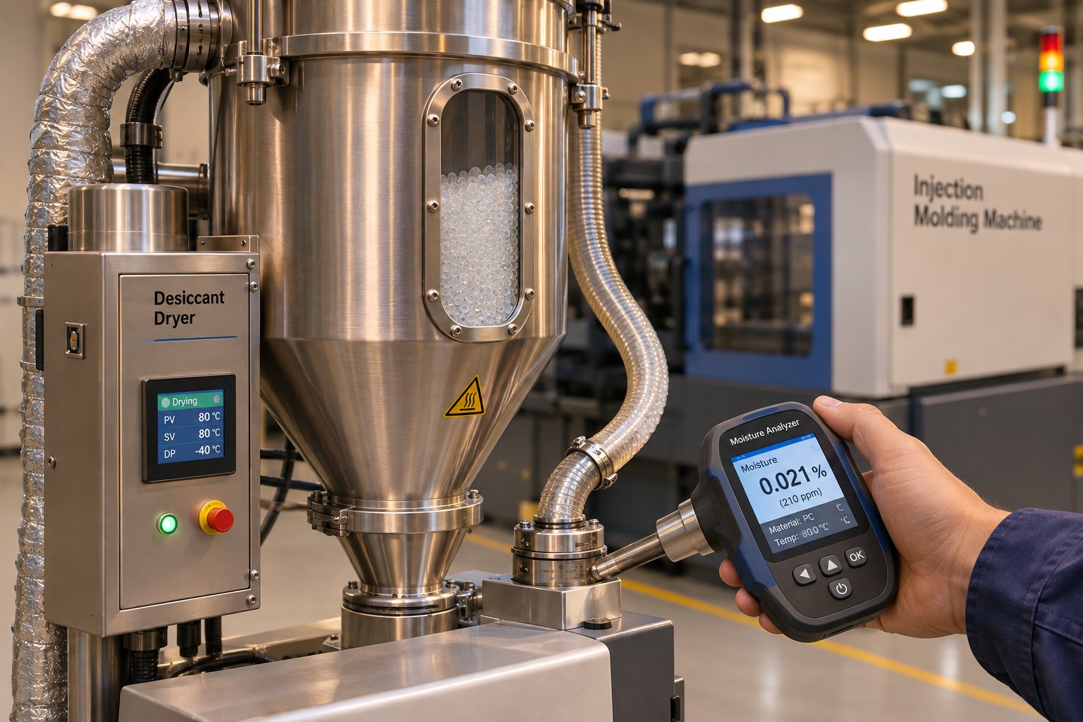
Not all plastics interact with water the same way. Hygroscopic polymers — including PA6, PA66, PC, ABS, PET, PBT, PMMA, and TPU — chemically absorb moisture deep into the pellet structure. The water molecules bond to polar groups within the polymer chain, particularly carbonyl groups and nitrogen-bound hydrogen sites. This isn't surface condensation that a blast of warm air can blow off. It's moisture locked inside the pellet at a molecular level, and it requires a desiccant dryer operating at a controlled temperature for a sustained period to drive it out.
When these resins enter the barrel without adequate drying, the absorbed water vaporizes at melt temperature and generates steam bubbles throughout the polymer. The result is the classic moisture splay pattern — fine, widespread, fan-like streaks distributed along the entire flow path. But the damage goes deeper than cosmetics. For resins like PC, PA, and PET, moisture at melt temperature triggers hydrolysis — an irreversible chemical reaction that severs polymer chains, reduces molecular weight, and permanently degrades mechanical performance. A part molded from improperly dried nylon might look acceptable on the surface yet fail under impact because its molecular backbone has been quietly broken apart.
Even non-hygroscopic resins like PP, PE, and POM aren't immune. They don't absorb water internally, but they can carry surface moisture — especially in humid production environments or after sitting in open containers overnight. That surface water is enough to flash into steam during plasticization and leave splay marks on an otherwise well-processed part. A simple hot-air dryer or even a brief pass through a dehumidifying hopper typically handles surface moisture on these materials, but ignoring it entirely is a common and avoidable mistake.
Resin Drying Reference Table
The table below consolidates drying parameters for the most commonly molded hygroscopic and non-hygroscopic resins. These values reflect published processing guidelines and manufacturer datasheet ranges. Always cross-reference with the technical data sheet (TDS) for your specific grade, since fillers, flame retardants, and other additives can shift the recommended conditions.
| Resin | Recommended Drying Temperature | Minimum Drying Time | Maximum Allowable Moisture Content | Silver Streak Susceptibility |
|---|---|---|---|---|
| PA6 / PA66 (Nylon) | 80 °C (176 °F) | 4–6 hours | < 0.20% | High |
| PC (Polycarbonate) | 120 °C (248 °F) | 3–4 hours | < 0.02% | High |
| PET (Polyethylene Terephthalate) | 150–170 °C (302–338 °F) | 4–6 hours | < 0.005% | High |
| PBT (Polybutylene Terephthalate) | 120–140 °C (248–284 °F) | 2–4 hours | < 0.02% | High |
| PC/ABS Blend | 100–110 °C (212–230 °F) | 3–4 hours | < 0.04% | High |
| ABS | 80–85 °C (176–185 °F) | 2–4 hours | < 0.10% | Medium |
| PMMA (Acrylic) | 80–90 °C (176–194 °F) | 2–4 hours | < 0.10% | Medium |
| TPU (Thermoplastic Polyurethane) | 80–110 °C (176–230 °F) | 2–4 hours | < 0.02–0.05% | Medium–High |
| PP (Polypropylene) | 80–90 °C (176–194 °F) if needed | 1–2 hours (surface moisture only) | Generally not critical | Low |
| PE (Polyethylene) | 80 °C (176 °F) if needed | 1–2 hours (surface moisture only) | Generally not critical | Low |
| POM (Acetal) | 80–100 °C (176–212 °F) if needed | 2 hours (surface moisture only) | Generally not critical | Low |
Notice the spread. PC demands 120 °C for 3–4 hours and a target below 0.02% moisture — conditions that ABS would never need. PET pushes even higher, requiring drying temperatures above 150 °C and an extremely tight moisture ceiling below 0.005%. Nylons, meanwhile, tolerate a comparatively generous 0.20% maximum but absorb moisture faster and more aggressively than almost any other engineering resin, meaning they re-absorb quickly if left sitting after drying. Understanding these resin-specific injection molding drying parameters is often the difference between solving silver streaks on the first attempt and chasing phantom process issues for hours.
One important nuance: the drying times listed are minimums assuming pellets start at a moderate, typical moisture level. Material that has been exposed to high humidity for extended periods — or regrind with its higher surface area — will take significantly longer to dry to target. As The Madison Group's engineering team emphasizes, letting the actual measured moisture level of the resin determine drying duration is far more reliable than relying on a fixed time alone.
Common Drying Mistakes That Cause Moisture Splay
Knowing the correct parameters is only half the battle. On a busy production floor, even well-intentioned drying setups can fail in ways that send wet material straight into the barrel. These are the practical errors that repeatedly cause moisture splay in injection molding:
- Hopper lids left open. Every time the hopper lid comes off and stays off — for sampling, for material additions, during shift changes — ambient humidity floods the drying environment. Hygroscopic pellets near the top of the hopper begin re-absorbing moisture almost immediately. A few minutes of exposure in a humid plant can undo hours of drying in the top layer of material.
- Exhausted desiccant beds. Twin-tower and rotary-wheel desiccant dryers rely on desiccant media to strip moisture from recirculating air. When the desiccant saturates and the regeneration cycle fails or falls behind, the dryer is circulating warm but moisture-laden air — effectively just heating the pellets without actually drying them. Dew point monitoring catches this, but many facilities rely solely on the dryer's temperature readout, which gives no indication of air moisture.
- Dryer set-point drift. Temperature controllers age. Thermocouples degrade. A dryer that reads 120 °C on the display may actually be delivering 105 °C air to the hopper. At the lower actual temperature, drying time extends well beyond the planned window, and material enters the barrel above the moisture threshold. Periodic calibration checks are essential.
- Material sitting in open gaylords or bags overnight. Hygroscopic resin that was perfectly dry at the end of a Friday shift can absorb enough moisture by Monday morning to produce immediate splay on startup. Unsealed bags, open gaylords, and floor-level storage in humid environments accelerate this re-absorption. Resealing unused material in airtight containers or foil-lined bags is a simple habit that prevents a common Monday-morning headache.
- Not verifying actual pellet moisture before production. This is the most consequential mistake. Dryer readouts, dew-point monitors, and timer-based assumptions all measure the drying environment — none of them directly tell you the moisture content of the pellets themselves. The only reliable confirmation is a direct measurement using a moisture analyzer, whether gravimetric, Karl Fischer, or sensor-based. Pulling a sample from the feed throat and testing it before the first shot of a run takes minutes and eliminates the single most common cause of splay-related scrap.
A useful benchmark from Plastics Today's troubleshooting series: if a press will be down for four hours or more, bank the dryer temperature down to approximately 100 °F (38 °C). This keeps material warm enough to prevent re-absorption without risking over-drying — a condition that can itself degrade heat-sensitive additives and embrittle certain resins.
How to solve silver streaks in injection molding often comes down to one discipline: verify actual pellet moisture with an analyzer before every production run, not just when splay appears.
Moisture, though, accounts for only one of the five volatile sources. Even with perfect drying, splay will persist if the true culprit is excessive shear at the gate, thermal degradation in the barrel, or trapped air with no escape path — each of which demands an entirely different corrective strategy.
Shear, Thermal Degradation, and Trapped Air as Root Causes
Your dryer is verified, the moisture analyzer reads well below threshold, and the pellets are bone-dry. Yet the streaks persist. This is the exact moment many molders stall — because the most frequently repeated advice in the industry ("dry your material") has run out of answers. The remaining three volatile sources — shear-induced degradation, thermal breakdown, and trapped air — each generate gas through a completely different mechanism, and each demands its own corrective strategy. Lumping them together under "check your process settings" guarantees wasted hours. Breaking them apart and tackling each one with targeted parameter changes is what actually clears the parts.
Shear-Induced Splay and Injection Speed Profiling
When molten polymer is forced through a restriction at high velocity, the long-chain molecules experience intense mechanical stress. Imagine pushing thick honey through a narrow funnel at speed — the material near the walls stretches and deforms violently. In a polymer melt, that violent deformation is called shear. When shear forces exceed the polymer's tolerance, molecular chains physically break apart. Those broken chains release volatile byproducts — small-molecule fragments and gases — that nucleate into bubbles and produce the coarse, localized streaks characteristic of shear splay.
The usual trouble spots? Undersized gates, thin-wall transitions, sharp corners, and narrow runner sections. Any geometry that forces the melt to accelerate rapidly or change direction abruptly concentrates shear energy at that point. You'll notice the streaks clustering right at or just downstream of these restrictions, fading as the melt decelerates into wider sections. That location-dependent pattern is your diagnostic fingerprint for shear splay injection molding causes.
The most powerful corrective tool here is a multi-stage injection speed profile — rather than filling the cavity at a single constant velocity. Here's how to structure it:
- First stage (through the gate): Set a slower velocity — typically 30-50% of your mid-fill speed. This reduces shear at the point of highest restriction, where the melt transitions from the runner into the cavity. The gate is almost always the narrowest cross-section the material encounters, so slowing down here has an outsized impact on volatile generation.
- Second stage (mid-fill): Increase speed to fill the bulk of the cavity efficiently. With the melt past the gate restriction and flowing through a wider cross-section, shear drops naturally and higher velocity is tolerable.
- Third stage (approaching pack transition): Slow the velocity again as the cavity nears full volume. This prevents the melt front from slamming into the end-of-fill region, which can both compress trapped air and generate a final shear spike at the flow front.
An effective injection speed profile to prevent silver streaks treats fill velocity as a variable that adapts to cavity geometry — not as a single number you set and forget. If profiling alone doesn't eliminate gate-region splay, consider whether the gate itself needs to be enlarged. A gate that's too small for the part volume and wall thickness will generate excessive shear no matter how slowly you push material through it.
Additional corrective actions for shear-driven splay include:
- Reduce overall injection speed as a first diagnostic step — if streaks vanish, shear was the dominant driver.
- Increase mold temperature slightly to keep the melt surface pliable longer, reducing frictional stress at the cavity wall.
- Lower screw RPM and back pressure during plasticization if shear splay shows up in the purge stream, indicating the damage is occurring before injection even begins.
- Inspect the screw and barrel for excessive wear — a worn check ring or scored barrel bore creates uncontrolled shear zones that degrade material unpredictably.
Thermal Degradation Splay and Barrel Temperature Strategy
Thermal degradation splay marks in injection molding arise from a different mechanism than shear, even though both involve breaking polymer chains. Here, the culprit is heat — too much of it, for too long. Every polymer has a processing temperature ceiling. Exceed it, or hold the material at melt temperature for an extended period, and the molecular chains begin to thermally decompose. The decomposition releases volatile gases (often small hydrocarbon fragments, CO, or CO2 depending on the resin) that form the brownish-tinted, irregularly distributed streaks that characterize this splay type.
Three scenarios drive thermal degradation on the production floor:
- Excessive melt temperature. The metering zone or nozzle is set higher than the resin can tolerate, or — more subtly — the actual melt temperature exceeds the setpoint because shear energy is adding heat the controller doesn't account for. As MD Plastics' barrel temperature guide emphasizes, barrel setpoints and true melt temperature can differ by 20-40 degrees Fahrenheit because heater bands only heat the barrel wall while shear, screw design, and backpressure determine what the polymer actually experiences.
- Prolonged residence time. When the barrel capacity is significantly oversized for the shot weight, material sits at melt temperature through multiple screw-recovery cycles before it's finally injected. Each additional cycle extends the thermal exposure. Long cycle times, production interruptions, and slow-running molds all compound this effect. The material closest to the barrel wall and in dead spots behind the check ring degrades first, sending intermittent degraded streaks into otherwise healthy shots.
- Localized hot spots. A miscalibrated thermocouple, a failing heater band, or an unbalanced hot-runner zone can create a single overheating point that degrades a portion of the melt while the rest remains within spec. The result is sporadic degradation splay that's maddening to track because the overall barrel profile looks correct on the controller display.
Corrective actions for thermal degradation splay follow a controlled, incremental approach:
- Reduce metering-zone temperature in 10-15 °C increments. Allow 10-15 full cycles between each change to let the system stabilize before re-evaluating. Rushing this step masks the effect of each adjustment.
- Shorten cycle time where possible. Even a few seconds off the cooling phase reduces total residence time and limits thermal exposure. If cycle time is fixed by part requirements, evaluate whether a smaller-diameter barrel would better match the shot size.
- Check thermocouple calibration. A thermocouple reading 10 °C low means the barrel is running 10 °C hotter than you think. Annual calibration is standard; quarterly is better for high-precision or high-temperature applications.
- Inspect hot-runner zone balance. Compare actual melt temperature at each drop. A single zone running 15-20 °C above its neighbors can degrade material in that channel while other cavities fill cleanly — producing the puzzling "splay in one cavity but not others" pattern.
- Verify heater band contact and condition. Bands that have air gaps, oxidation buildup, or loose mounting clamps deliver uneven heat and force adjacent zones to compensate, creating unpredictable thermal gradients along the barrel.
Trapped Air and Decompression Splay
Trapped air silver streaks in injection molding look similar to moisture splay at first glance, which is exactly why they get misdiagnosed so often. The mechanism, however, is entirely different. No chemical decomposition is involved. Instead, air that's physically present in the melt — drawn in during screw recovery, trapped in the feed throat, or compressed ahead of the melt front in an inadequately vented cavity — expands and bursts at the part surface, leaving bubble-like or spray-pattern marks.
Where does the air come from? Three primary pathways:
- Excessive screw decompression (suck-back). After the screw finishes recovery and stops rotating, most machines pull the screw back slightly to relieve pressure at the nozzle and prevent drool. Too much suck-back creates a vacuum at the screw tip that draws air into the melt. Asaclean's processing guidelines recommend limiting decompression distance to no more than 1.5 times the travel of the check ring. Exceed that, and you're pulling air directly into the shot.
- Inadequate cavity venting. As the melt front advances, it pushes air ahead of it toward the parting line and vents. If those vents are too shallow, clogged with offgas residue, or simply absent in critical locations, the compressed air has nowhere to go. It gets forced back into the melt surface — or trapped at weld lines and end-of-fill regions — and flashes into splay marks upon contact with the cooler mold wall.
- Air ingestion at the feed throat. A starved feed zone — where pellets aren't consistently filling the screw flights — allows air pockets to ride down the barrel with the material. Low back pressure compounds this by failing to compress out those air pockets during plasticization. The result is air entrained in the melt before it ever reaches the nozzle.
Corrective actions for air-based splay target the air entry point directly:
- Reduce suck-back distance. Start by cutting it in half and observe whether the splay diminishes. Many processors set suck-back at startup and never revisit it — even when it's far more than the check ring requires.
- Verify vent depths are at specification. For most amorphous resins, vent depths of 0.025-0.050 mm (0.001-0.002 in) at the parting line are typical; semi-crystalline resins with lower melt viscosity may require shallower vents to avoid flash. Vents clogged by offgas deposits should be cleaned on a regular schedule — not just when splay appears.
- Increase back pressure moderately. A modest increase (25-50 psi / 1.7-3.4 bar) compresses air out of the melt during screw recovery. Avoid dramatic increases, which add shear heat and can shift you from an air problem into a shear or degradation problem.
- Confirm the feed throat is not starved. Check that pellets are flowing freely into the screw flights. Bridging at the hopper throat — caused by high feed-zone temperatures, static cling, or irregular pellet geometry — creates gaps that let air into the conveying zone. Lowering the feed-zone temperature or adding a slight vibration to the hopper often resolves this.
- Slow initial injection speed. A slower melt-front velocity gives trapped air more time to escape through vents before the surface freezes. This is especially effective for deep-rib and boss geometries where air tends to compress at the base of the feature.
Each of these three non-moisture volatile sources — shear, thermal degradation, and trapped air — produces splay through a distinct physical mechanism. Shear tears polymer chains apart mechanically. Heat breaks them apart chemically. Air simply has no exit path. The corrective actions don't overlap, which is exactly why the diagnostic elimination workflow from the previous section matters so much: applying a thermal fix to a shear problem, or a venting fix to a degradation problem, won't move the needle.
Yet some of the trickiest silver streak cases on the production floor don't fit neatly into a single root-cause category. They shift location over time, appear only in specific cavities, or show up hours into a stable run. Those pattern-based scenarios demand a different diagnostic lens — one that starts from what you see on the floor and works backward to the source.
Troubleshooting Splay Marks by Symptom on the Production Floor
Root-cause theory is valuable at the whiteboard. On the shop floor, though, you're not staring at a textbook — you're staring at a part. The streaks are in a specific place. They showed up at a specific time. They may be hitting one cavity and skipping the next. That context — the where and the when — is the fastest diagnostic tool you have, and it doesn't require a moisture analyzer, a temperature probe, or a barrel teardown to use. It requires observation.
The scenarios below cover the five symptom patterns that account for the vast majority of silver streak complaints in production. Each one starts with exactly what you see at the press, then traces that pattern backward to the most probable volatile source. Troubleshooting splay marks in injection molding this way cuts diagnostic time dramatically because the symptom itself eliminates most candidates before you change a single parameter.
Silver Streaks Near the Gate Only
You pull the part and the splay is concentrated in a tight zone right around the gate — sometimes radiating outward an inch or two, sometimes confined to just the gate vestige area. Move your eyes past that region, and the rest of the part surface is clean. Shot after shot, the pattern repeats in the same location.
This is classic shear splay territory. The gate is the narrowest restriction the melt encounters, and when injection speed during the first stage is too aggressive — or the gate cross-section is simply undersized for the flow rate — polymer chains are mechanically torn apart at that choke point. The resulting volatile fragments nucleate into bubbles right at the gate and get dragged a short distance downstream before the melt decelerates and the shear drops.
What to try first:
- Reduce the first-stage injection velocity by 30-40% while keeping the rest of the speed profile unchanged. If the gate-region splay clears up, you've confirmed shear as the driver.
- Examine the gate dimensions. A gate that's too small for the part volume and wall thickness will generate excessive shear regardless of how slowly you push material through it. Compare your gate cross-section against the resin supplier's recommended shear-rate limits.
- Check for sharp edges or burrs at the gate orifice. Even a small machining imperfection can create a localized shear spike that degrades material at that exact point.
If the streaks persist after slowing the fill and the gate geometry checks out, consider whether a valve gate is introducing air. Improperly timed valve-gate opening can momentarily expose the melt channel to an air pocket that gets injected with the first slug of material — producing splay that looks like shear but is actually air entrapment at the gate.
Streaks at End of Fill or on Last Cavity to Fill
The opposite pattern: the gate region and the first 80% of the part look flawless, but the last areas to fill — far corners, thin ribs, boss tops, or weld-line intersections — show distinct silver streaks or bubble-like marks. In a multi-cavity mold, you might notice that the last cavity to fill is the only one with splay.
This points directly to trapped air. As the melt front advances, it compresses the air ahead of it like a piston. In a well-vented mold, that air escapes through parting-line vents, ejector-pin clearances, and vent inserts before the melt front arrives. In an inadequately vented mold — or one where offgas residue has gradually clogged the vents — the compressed air has nowhere to go. It gets folded back into the melt surface or squeezed into the last-fill region, where it ruptures into splay as the skin layer forms.
Your corrective sequence here is straightforward:
- Inspect vent condition at the last-fill locations. Clogged vents are the single most common finding. Clean them with a brass brush, never steel, to avoid enlarging the slot.
- If vents are clean but splay persists, measure vent depth. For most amorphous thermoplastics, parting-line vents should be 0.025-0.050 mm deep. Vents that are too shallow restrict airflow without preventing flash; vents that don't exist at the end-of-fill zone are a mold-design gap that needs correction.
- Temporarily reduce injection speed during the final 10-15% of fill. If the splay diminishes, the air had more time to escape — confirming that venting capacity is the bottleneck, not the material or barrel.
In extreme cases, compressed air at end of fill can auto-ignite and leave burn marks — the so-called diesel effect. Silver streaks at the end of fill are the early warning sign that venting is approaching that threshold.
Streaks on First Shots Only That Disappear After Running
Imagine this: you start the press after a weekend shutdown and the first five to ten shots show clear splay. Then, without changing a single process parameter, the streaks gradually fade and the parts run clean. By the fifteenth or twentieth shot, the defect is gone entirely.
This pattern almost always traces to residual moisture or degraded material in the barrel from the previous shutdown. When the machine sits idle, hygroscopic resin left in the barrel absorbs ambient moisture through the feed throat and nozzle. During a cold start, this moisture-laden or partially degraded material is the first to be injected. It takes several shots to purge that compromised material out and replace it with fresh, properly dried melt.
Contributing factors include:
- Inadequate purging before production. A quick three-shot purge after startup rarely clears the full barrel volume. Depending on the machine's barrel capacity relative to shot size, it can take ten or more full shots to completely displace old material.
- Condensation on the mold surface. If the mold was sitting at ambient temperature overnight and the shop is humid, water condenses on the cold cavity steel when the mold is first closed. The first few shots flash that surface condensation into steam, producing splay that has nothing to do with the resin or barrel. Running a few warm-up cycles with mold heating engaged before starting production eliminates this source.
- Cold-slug injection. Material that solidified in the nozzle tip or sprue bushing during shutdown gets pushed into the cavity on the first shot. This degraded, semi-solid slug can carry trapped air and decomposition byproducts that create splay only on that initial cycle.
The fix is procedural: establish a startup protocol that includes a thorough purge — enough shots to cycle the full barrel volume at least once — and verify mold surface temperature before accepting parts. If you're running a hygroscopic resin, confirm the dryer has been operating at setpoint long enough to re-dry any material exposed during the downtime.
Streaks in One Cavity but Not Others in a Multi-Cavity Mold
This scenario frustrates even experienced molders. You're running a four- or eight-cavity mold, and three out of four cavities produce perfect parts. The fourth shows consistent splay. Same material, same barrel, same shot — so how can one cavity behave differently?
The answer lies in the variables that aren't the same across cavities: runner balance, gate condition, venting, and hot-runner tip health. A multi-cavity mold silver streak in one cavity signals a localized issue, not a material or barrel problem. Here's where to look:
- Runner imbalance causing uneven shear. In naturally balanced runner systems, slight dimensional differences from machining tolerances or wear can send more material (and higher velocity) to one cavity than its neighbors. That cavity sees higher shear stress at the gate, generating localized shear splay. A short-shot progression study — filling the mold incrementally at 25%, 50%, 75%, and 90% of volume — reveals whether one cavity fills consistently faster or slower than the rest, pointing to a runner or gate dimensional mismatch.
- Localized venting blockage. One cavity's vents may be clogged with offgas deposits while the others are clear. This is especially common in molds running resins with high filler content or flame-retardant packages, which generate more offgas residue. Cleaning the vents in the affected cavity often eliminates the splay immediately.
- Hot-runner tip degradation in a single drop. In hot-runner molds, a damaged or worn nozzle tip in one drop can create a flow restriction that generates excessive shear, or a gate-seal issue that allows air to enter the melt stream. Temperature control problems in a single hot-runner zone — a broken thermocouple, a failing heater, or a loose connector — can overheat or underheat material in that channel, producing degradation splay or cold-slug splay in only that cavity.
The diagnostic shortcut: if the splay consistently follows one cavity regardless of process changes, the root cause is mechanical and mold-specific. No amount of barrel temperature adjustment or drying will fix it. You need to inspect that cavity's runner, gate, vent, and hot-runner components individually.
Silver Streaks After Hours of Stable Production
Perhaps the most disorienting scenario: the press has been running clean parts for three, five, even eight hours — then splay gradually begins appearing and worsens over the next hour. Nothing changed on the controller. No one adjusted a parameter. Yet the defect crept in.
Several time-dependent mechanisms cause silver streaks after hours of production molding:
- Desiccant-bed exhaustion mid-run. Twin-tower desiccant dryers regenerate their beds on a timed cycle. If the regeneration cycle is set too long relative to the moisture load, or if the desiccant media has degraded from age, the active bed saturates before the switch. For 30 minutes to an hour, the dryer circulates warm, moisture-laden air — and the resin sitting in the hopper during that window absorbs enough moisture to produce splay once it reaches the barrel. Monitoring dew point at the dryer outlet catches this before it reaches the press.
- Gradual thermal degradation from residence-time creep. This happens subtly. Maybe the cycle time drifted upward by a few seconds because of a sticky ejector, a slow robot, or an operator pause. Each added second means the material sits at melt temperature longer. Over hours, this incremental increase accumulates enough thermal exposure to push the resin past its degradation threshold. Cycle-time monitoring alarms are the simplest preventive measure.
- Regrind percentage drift from the granulator. Many operations feed regrind back into the process from a beside-the-press granulator. If the virgin-to-regrind blending ratio isn't precisely metered, the regrind percentage can creep upward during a long run — especially if the granulator output rate fluctuates or if the virgin material feed hopper runs low. Since regrind has already been through at least one heat history, a rising regrind percentage means more thermally sensitive material entering the barrel, and a gradual onset of degradation splay.
The common thread in all three scenarios is that the root cause is dynamic, not static. Something changed during the run — even though no human intentionally changed a parameter. Recognizing that silver streaks which appear mid-run are almost always driven by a drifting input, not a fixed process error, reframes your troubleshooting entirely. Instead of re-examining barrel temperatures and injection profiles, look at what has shifted since the run began: dryer performance, cycle consistency, and material blend ratios.
Matching the symptom pattern to the timeline and location eliminates most root causes faster than adjusting parameters blindly. Where the splay appears tells you what's wrong; when it appears tells you why it started.
These symptom-based scenarios cover the most common production-floor situations, but they share one assumption: the mold and part design are fundamentally sound. When streaks persist despite correct process settings and verified material condition, the root cause often lives in the tool steel itself — in gate dimensions that can't be process-tuned away, in venting that was never adequate to begin with, or in wall-thickness transitions that guarantee turbulence. Those design-driven factors deserve their own examination.
Mold Design and Part Geometry Factors You Cannot Process Away
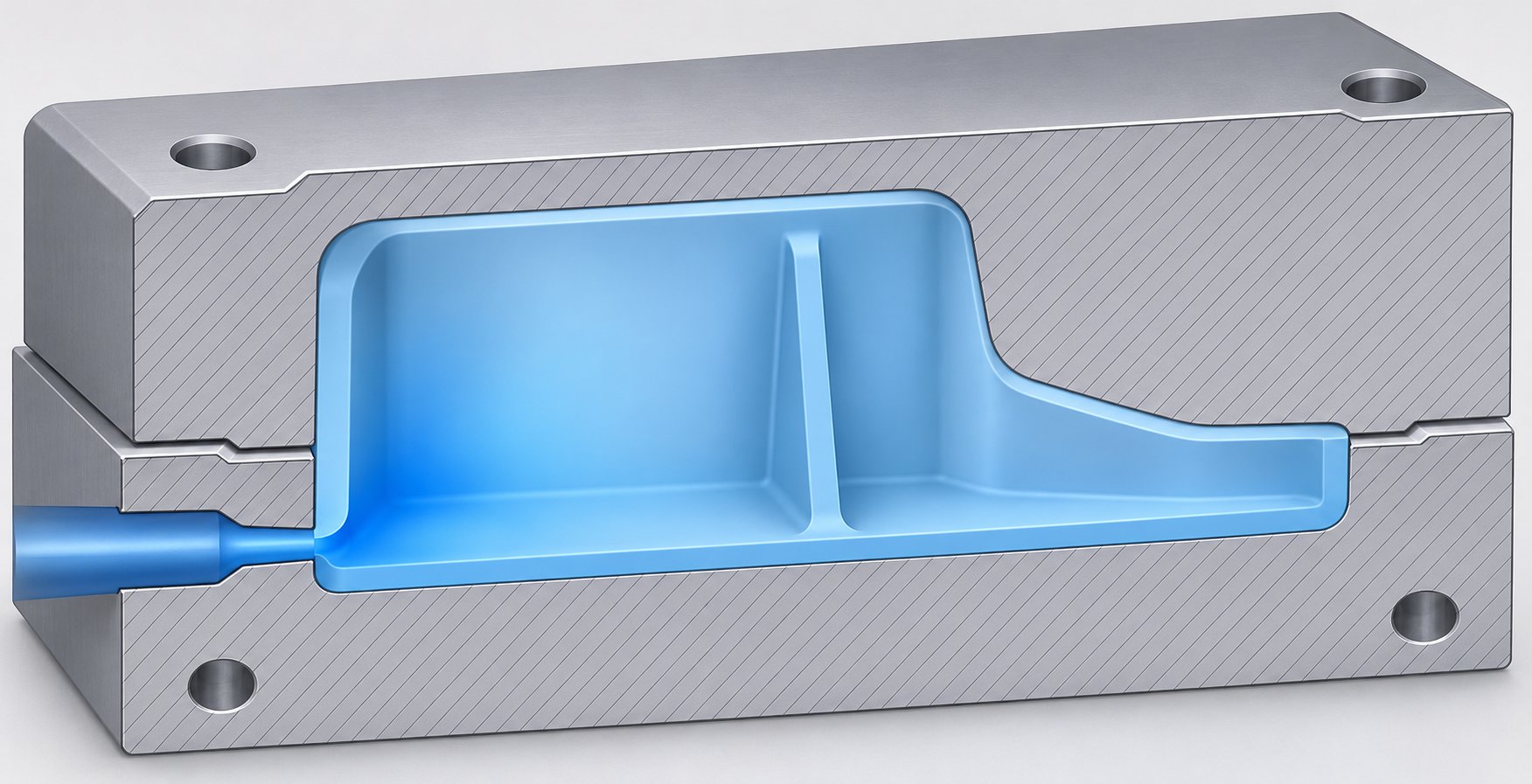
Every troubleshooting scenario discussed so far assumes the mold itself is fundamentally sound — that the gate is correctly sized, the vents are deep enough, and the part geometry allows smooth, uniform filling. That assumption breaks down more often than most molders want to admit. When mold design causes of silver streaks in injection molding are the true root issue, no combination of barrel temperature adjustments, speed profiling, or drying improvements will make them disappear. You'll spend an entire shift optimizing parameters only to find the streaks exactly where you left them, shot after shot, in the same location, at the same intensity.
Recognizing when the problem lives in the steel — not the process — saves enormous time and frustration. These are the three mold-design and geometry categories that most commonly drive persistent splay.
Gate Type, Size, and Location Impact
The gate is the single most influential geometric feature for silver streak formation. It's the narrowest cross-section the melt passes through, and everything that happens there — shear rate, velocity, pressure drop, and turbulence — radiates downstream into the cavity. An undersized gate forces the melt through a tighter restriction than the polymer can tolerate at the required fill rate. The shear stress at that choke point tears polymer chains apart, releasing volatile fragments that nucleate into bubbles before the melt has traveled even an inch past the gate. This is why gate size and splay marks in injection molding are so tightly linked: even a gate that's 10-15% too small for the application can push shear rates above the degradation threshold for sensitive resins like PC or PMMA.
Gate location matters just as much as gate size. Imagine a gate positioned so the melt must immediately flow from a thick section into a thin wall — a thick-to-thin transition. The melt accelerates sharply at the transition, creating a localized shear spike. The thin section also freezes faster, so the melt front hesitates at the boundary before surging forward once injection pressure overcomes the resistance. That hesitation-and-surge pattern entraps air at the transition zone, producing splay marks that appear consistently at the same spot regardless of process settings. A better gate location — one that allows the melt to enter the thickest wall section first and flow gradually toward thinner areas — eliminates this geometry-driven turbulence entirely.
Valve gates introduce an additional variable: timing. When a valve gate opens, a mechanical pin retracts to expose the melt channel. If the pin opens too late relative to the injection start, a brief burst of air can enter the melt stream ahead of the plastic, producing splay on the first shot or intermittent splay during steady-state running. If the pin doesn't retract fully, it creates a partial obstruction that acts like an undersized gate — concentrating shear and generating degradation at the gate tip. As FirstMold's splay mark analysis highlights, residual plastic in dead ends around hot-runner nozzle tips and improperly positioned temperature sensors compound the problem by allowing degraded material to intermittently flush into the cavity.
Runner System Design and Venting Adequacy
Runners are the highway system delivering melt to each cavity. When that highway is unbalanced — one branch shorter, wider, or smoother than its neighbors — cavities receive melt at different velocities and shear histories. The cavity fed by the shorter, faster runner sees higher shear at its gate. The cavity at the end of a longer runner receives material that has spent more time at melt temperature, making it more prone to thermal degradation. In both cases, the result can be splay in specific cavities while others fill cleanly, a pattern that's nearly impossible to resolve through process adjustments alone.
Cold slugs represent another runner-driven splay source. During each cycle, a small amount of material at the nozzle tip or sprue bushing cools and partially solidifies. When the next shot fires, this cold slug gets pushed into the runner system. If the cold-slug well at the base of the sprue is undersized or missing, the slug travels into the cavity, carrying degraded material and trapped air pockets with it. The result is erratic splay — sometimes concentrated near the gate, sometimes distributed unpredictably — that appears sporadically and doesn't correlate with any process parameter change.
Venting, though, is the most consistently underengineered feature in mold design. A mold can have perfect gate geometry and balanced runners yet still produce splay if the air ahead of the melt front has no escape route. The goal of venting to prevent silver streaks in injection molding is simple: provide a path for displaced air and volatiles to exit the cavity at the same rate the melt fills it. When vents are too shallow, too few, or positioned away from the actual last-fill areas, compressed air gets folded into the melt surface.
Asaclean's venting guide provides vent-depth guidelines by resin family that serve as practical starting points for mold designers and process engineers:
| Resin Family | Recommended Vent Depth (mm) |
|---|---|
| PP / PE | 0.013 - 0.030 |
| ABS | 0.025 - 0.038 |
| PA (Nylon) | 0.008 - 0.013 |
| POM (Acetal) | 0.013 - 0.025 |
| PC (Polycarbonate) | 0.038 - 0.064 |
| PVC | 0.013 - 0.018 |
| HIPS | 0.020 - 0.030 |
| PET / PBT | 0.013 - 0.018 |
| TPE | 0.013 - 0.018 |
Notice the range. Nylon requires the shallowest vents (0.008-0.013 mm) because its low melt viscosity allows it to flash easily into wider openings. Polycarbonate, with its much higher viscosity, tolerates — and actually needs — deeper vents (up to 0.064 mm) to allow adequate gas escape. Using a single generic vent depth across all resins is one of the most common mold-design oversights, and it directly contributes to persistent air splay in resins that need wider vent channels.
Even correctly dimensioned vents degrade over time. Offgas deposits — wax-like residues from additives, flame retardants, and processing aids — gradually narrow the vent channel. A vent that measured 0.030 mm when the mold was new may effectively be 0.015 mm after a thousand shots. Scheduled vent cleaning at documented intervals, rather than reactive cleaning only after splay appears, is the only reliable way to maintain venting performance across a production campaign.
Wall Thickness Transitions and Rib-to-Wall Ratios
Plastic wants to be the same thickness everywhere. That principle, emphasized by Wise Plastics' DFM guidelines, is the root of a large category of wall thickness silver streaks in plastic parts. When the melt front flows from a thick section into a thin section — an abrupt wall-thickness transition — two things happen simultaneously. First, the leading edge of the melt hesitates as it encounters the higher flow resistance of the thinner passage. Then, once injection pressure overcomes that resistance, the melt surges forward rapidly. That hesitation-and-surge sequence creates a void at the transition point where air gets sucked into the melt front, producing splay marks that appear consistently at the thickness change, cycle after cycle.
Jetting is the extreme version of this behavior. When a small gate opens into a much thicker cavity section, the melt doesn't spread smoothly across the cavity floor — it shoots through like a stream of water from a hose, folding back on itself and trapping pockets of air as it tumbles. Those air pockets show up as splay, voids, or a combination of both on the finished part.
Ribs introduce a related but subtly different problem. A rib meeting a wall creates a locally thick intersection — more plastic concentrated in a small zone. When the rib-to-wall thickness ratio is too high (the rib base is thicker than roughly 50-60% of the adjacent wall), two defects compete. On the cosmetic side, you get sink marks over the thick intersection. But from a splay perspective, the deep channel of the rib generates significant shear heating as the melt is forced down its narrow length. Material at the rib base reaches temperatures well above the bulk melt, and for shear-sensitive resins, that localized overheating can degrade the polymer and release volatiles that show up as splay near the rib attachment.
Tall ribs compound the issue. Ribs taller than roughly three times the adjoining wall thickness fill poorly, trap air at the rib tip, and create dead-end pockets where gas has no escape route. Without dedicated rib venting — small vent inserts or sintered metal plugs at the rib terminus — that trapped air produces splay marks or burn marks at the top of every rib on every shot.
The critical takeaway is that none of these geometry-driven causes respond to process optimization. You can slow the injection speed, raise the mold temperature, or increase the pack pressure, and you might reduce the severity slightly — but the defect won't disappear entirely because the root cause is physical geometry, not a process parameter. Resolving wall thickness silver streaks in plastic parts requires tooling modifications (adding radii at transitions, tapering wall changes over at least three times the thickness difference) or part-design revisions (coring out thick sections, reducing rib-to-wall ratios).
Before investing more time in process parameter adjustments, run through this mold-design checklist to confirm the tool isn't the true bottleneck:
- Gate cross-section: Is the gate sized appropriately for the resin's recommended maximum shear rate and the required fill volume? Compare gate dimensions against the resin supplier's gate-sizing guidelines.
- Gate location: Does the melt enter at the thickest wall section and flow toward thinner areas, or is it forced through a thick-to-thin transition immediately after the gate?
- Valve-gate timing and pin condition: Are valve gates opening fully and on time? Is there wear or buildup on the pin that restricts the melt path?
- Runner balance: Do all cavities fill at the same rate, or does a short-shot study reveal one cavity consistently leading or lagging?
- Cold-slug well adequacy: Is the cold-slug well deep enough to capture the full volume of cooled material from the nozzle tip between shots?
- Vent depth and location: Are vents present at every last-fill area, weld-line region, and rib terminus? Do vent depths match the resin family's recommended range?
- Vent condition: When were vents last inspected and cleaned? Is there a documented cleaning schedule based on resin offgas characteristics?
- Wall-thickness uniformity: Are there abrupt thickness transitions greater than 25% of nominal wall without a taper of at least 3:1 length-to-thickness-difference ratio?
- Rib-to-wall ratio: Are rib bases held at or below 60% of the adjoining wall thickness? Are ribs taller than 3x nominal wall vented at the tip?
If two or more items on that list flag issues, tooling or design corrections should take priority over further process experimentation. A mold with a fundamentally undersized gate or missing vent channels will never produce consistently splay-free parts, regardless of how precisely you dial in barrel temperatures, injection profiles, and drying parameters.
Design and tooling, however, represent just one layer of the problem. Even a perfectly designed mold can develop splay issues over time if the material feeding into it carries hidden baggage — degraded regrind with weakened molecular chains, trace contamination from a previous run, or the slow thermal breakdown that comes from material sitting too long in an oversized barrel. Those creeping, time-dependent factors are easy to overlook precisely because they don't show up on the mold print or the process setup sheet.
Regrind, Contamination, and Residence Time as Hidden Culprits
A mold can be vented perfectly, gates sized to spec, and drying parameters dialed in to the decimal — yet silver streaks still appear. When the obvious suspects have been ruled out, two under-discussed contributors tend to be lurking in the background: the material's history before it reaches the barrel, and how long it sits inside the barrel once it gets there. Regrind causing silver streaks in injection molding and residence-time-driven degradation share a common thread — both involve polymer chains that have already been weakened before the melt ever reaches the cavity. And because neither one shows up on a process setup sheet, they're among the easiest root causes to overlook.
How Regrind Percentage and Contamination Trigger Splay
Every pellet of regrind has already survived at least one full heat cycle — melting, shearing through a screw, injecting at high velocity, cooling, and then being ground back into granules. That thermal and mechanical history shortens polymer chains, reduces molecular weight, and makes the material measurably more vulnerable to further degradation the next time it's processed. Think of it like reheating cooking oil: once is fine, twice is tolerable, but each pass degrades quality a little more. At the molecular level, those shorter, weaker chains decompose at lower temperatures and generate volatile byproducts more readily than fresh virgin resin.
For engineering resins like PC, PA, and PBT, industry guidelines generally recommend keeping regrind at or below 30% of the total blend to avoid compromising mechanical properties. In practice, many processors targeting tight cosmetic standards on these resins limit regrind to 20-25% — and even that range assumes the regrind has been through only a single prior heat history. Multi-pass regrind, where material has been reprocessed two or three times without tracking, pushes degradation risk significantly higher. The volatiles released from this weakened material create the characteristic brownish-tinted, irregularly distributed streaks of degradation splay — often indistinguishable from barrel-temperature-driven thermal degradation unless you know the regrind content has been creeping upward.
Contamination splay in plastic molding follows a different but equally insidious path. Even trace amounts of an incompatible resin — a few PE pellets mixed into a PC blend, residual POM left in the barrel from a prior run, or an off-spec colorant masterbatch — can decompose at the host resin's processing temperature and release gases that produce random, non-repeating silver streaks. The randomness is the diagnostic fingerprint: contamination splay doesn't correlate with gate location, fill sequence, or cavity position the way shear or air splay does. It shifts from shot to shot because the contaminant particles are unevenly dispersed in the melt.
Common contamination entry points include:
- Dirty regrind. Material collected from the granulator picks up dust, floor debris, oil, and sometimes stray pellets from adjacent machines. As Kaysun's engineering team notes, all regrind must be free of dust, dirt, skin oils, and foreign particulates — any of which can decompose at melt temperature and generate volatile-driven streaks.
- Incomplete barrel purging between resin changes. Residual material from a previous production run clings to screw flights, check-ring surfaces, and barrel-wall dead spots. When the new resin arrives at processing temperature, those remnants degrade and flush intermittently into the melt stream.
- Cross-contaminated masterbatch or additive packages. A colorant formulated for PP may decompose when processed at PC temperatures, releasing gases that nucleate into splay bubbles in the finished part.
The corrective approach for regrind and contamination silver streaks in plastic molding is prevention-first: maintain a regrind log that tracks blend percentage and number of prior heat-history cycles per batch, keep regrind storage containers sealed and labeled, purge the barrel thoroughly between material changes, and verify masterbatch compatibility with the base resin's full processing window — not just its nominal melt temperature.
Residence Time, Barrel Sizing, and Material Retention
Imagine filling a swimming pool to wash a single car. That's essentially what happens when a small-shot mold runs on a machine with a dramatically oversized barrel. The shot might consume only 15-20% of the barrel's melt capacity, meaning the remaining 80-85% of the material sits at melt temperature, cycle after cycle, waiting its turn to be injected. Each cycle that passes without the material moving forward adds another dose of thermal exposure. Over multiple cycles, that cumulative heat history degrades the polymer exactly the way excessive barrel temperature would — except the controller reads a perfectly normal setpoint the entire time.
Rosti's residence time guide outlines the recommended barrel utilization range: the shot size should consume between 25% and 65% of barrel capacity, with an additional 10% safety margin. Fall below that 25% floor, and residence time splay marks in injection molding become a near-certainty for heat-sensitive resins. Fall above 65%, and you risk poor melt homogeneity and extended screw recovery. Either extreme creates problems, but the undersized-shot scenario is more common — and more commonly misdiagnosed — because the parts may look fine for hours before the gradual accumulation of thermal degradation pushes volatile levels past the visible splay threshold.
Long cycle times and production interruptions compound the effect. A mold that cycles every 45 seconds on a barrel sized for 30-second cycles keeps material at melt temperature roughly 50% longer than intended. Unplanned downtime — a robot fault, a stuck ejector, a quality hold — extends residence time even further. If the barrel isn't banked to a lower holding temperature during extended stops, the material inside continues degrading silently.
Barrel sizing and silver streaks in injection molding aren't just about the barrel volume, though. The internal geometry of the plasticizing system plays a critical role in whether material moves cleanly through the system or hangs up in dead spots. A worn check ring — the valve at the screw tip that prevents backflow during injection — no longer seats tightly. Material leaks past it during injection and sits in the gap between the ring and the screw tip, exposed to melt temperature for far longer than the nominal residence time suggests. Over many cycles, this retained material degrades severely and periodically flushes into the melt stream as dark streaks or degradation splay.
A scored or worn barrel bore creates a similar problem on a larger scale. Material lodges in scratches and grooves along the barrel wall, creating micro dead spots where polymer chains break down and eventually release into the main melt flow. The wider the wear gap between screw flight and barrel ID, the more material hangs up and the longer its effective residence time becomes — even if the calculated residence time based on shot size and cycle time looks acceptable on paper.
Addressing residence-time and material-retention issues often requires looking beyond process parameters at the plasticizing hardware itself. When a screw and barrel are worn or mismatched to the application — oversized for the shot, worn past tolerance, or designed with a geometry that doesn't suit the resin's melting and mixing characteristics — no amount of temperature adjustment corrects the underlying retention problem. Molders evaluating whether their plasticizing components are correctly sized for the job can benefit from a technical review that considers screw geometry, wear condition, melting capacity, mixing performance, and material-retention characteristics together. NANHAIYA's custom injection molding screw barrels, for example, are engineered around machine specifications, resin characteristics, and shot requirements — helping match the screw and barrel to the application in a way that directly addresses the residence-time and degradation issues discussed here. That said, screw and barrel replacement is one piece of the puzzle, not a universal fix. If the root cause is an oversized machine for the mold, even a new screw won't solve the fundamental mismatch — right-sizing the machine or adjusting the mold assignment is the real corrective action.
The practical takeaway: if your diagnostic workflow has eliminated moisture, shear, air entrapment, and mold-design factors, turn your attention to what's happening inside the barrel. Check your regrind blend ratio and heat-history tracking. Calculate your actual barrel utilization percentage. Inspect the check ring and barrel bore for wear. These hidden culprits don't announce themselves the way a clogged vent or a wet hopper does — but they account for a significant share of the splay cases that resist every other corrective attempt.
A Long-Term Prevention Framework That Keeps Splay Off Your Parts
Fixing a silver streak problem once is troubleshooting. Preventing it from returning is a system. The difference between molding operations that battle chronic splay and those that rarely see it comes down to whether the corrective knowledge stays in a technician's head or gets built into documented, repeatable shop-floor routines. Every root cause covered in the preceding sections — moisture, shear, thermal degradation, trapped air, contamination, regrind, residence time, mold design — is preventable. But only if the prevention steps are formalized, assigned, and verified on a schedule rather than triggered reactively after scrap starts piling up.
Building a Silver Streak Prevention Checklist for Your Shop Floor
A silver streak prevention checklist for injection molding doesn't need to be complicated. It needs to be consistent. The sequence below prioritizes the highest-impact checks first and builds outward toward less frequent but equally important inspections. Print it, laminate it, and post it at the press.
- Validate material drying with moisture-analyzer spot checks every shift. Pull a sample from the feed throat — not the dryer hopper — and measure actual pellet moisture against the resin datasheet maximum. This single habit eliminates the most common volatile source before it ever reaches the barrel.
- Maintain a regrind log tracking blend percentage and heat-history cycles. Record how many times each regrind batch has been reprocessed. Cap the blend ratio at the resin manufacturer's recommendation — typically 20-25% for engineering resins — and retire multi-pass regrind before it degrades into a volatile source.
- Verify barrel utilization ratio for every mold setup. Calculate shot weight as a percentage of barrel capacity. If the shot consumes less than 25% of the barrel volume, flag the setup for a machine-sizing review. Residence-time-driven degradation is silent until it isn't.
- Perform scheduled vent cleaning at documented intervals. Base the frequency on resin offgas characteristics — flame-retardant and high-filler resins demand more frequent cleaning than unfilled commodity grades. Log each cleaning event so you can correlate vent condition with defect trends over time.
- Review and record injection-speed profiles for each mold in the setup sheet. A validated multi-stage speed profile — slower through the gate, faster mid-fill, slower at pack transition — prevents shear splay from recurring every time a mold is set up by a different technician. The profile belongs on the setup document, not in one person's memory.
- Inspect screw and barrel wear at defined intervals based on resin abrasiveness and throughput. Polysource's maintenance guidelines recommend annual measurements on the screw, barrel bore, and check ring assembly, logged and compared against previous readings to identify wear trends before they cause failures. Abrasive glass-filled or mineral-filled resins accelerate wear and may require more frequent checks.
This injection molding splay mark prevention system works because it addresses every volatile source systematically — moisture at the material level, regrind and contamination at the blend level, residence time at the machine level, venting at the mold level, shear at the process level, and wear at the hardware level. Skip any one layer, and that's the layer where splay eventually breaks through.
When to Escalate Beyond Process Adjustments
There's a point in every troubleshooting effort where continuing to adjust process parameters yields diminishing returns. Recognizing that inflection point — and knowing when to replace screw barrel components, modify tooling, or redesign part geometry — is what separates efficient problem resolution from an endless loop of incremental tweaks.
Consider escalating when:
- The diagnostic workflow has confirmed the root cause is mold-related (undersized gate, missing vents, runner imbalance), and no speed profile or temperature adjustment eliminates the defect entirely. Tooling modifications — gate resizing, vent additions, runner rebalancing — are the only path forward.
- Barrel utilization is chronically below 25%, and the splay pattern correlates with residence-time degradation. Moving the mold to a correctly sized press is the structural fix; parameter changes on an oversized machine are a temporary bandage.
- Screw and barrel measurements reveal wear beyond tolerance — flight-to-bore clearance exceeding manufacturer specifications, check-ring sealing surfaces scored or grooved, or barrel bore out of round. Worn plasticizing components create dead spots, uncontrolled shear zones, and material-retention pockets that no process setting can compensate for. When the hardware itself is the degradation source, replacement is the corrective action. NANHAIYA's custom injection molding screw barrels offer a tailored approach here — their technical review evaluates screw geometry, wear patterns, and resin-specific melting and mixing requirements to match the replacement components to the actual application, rather than defaulting to a generic off-the-shelf replacement. That specificity matters because a screw designed for the wrong resin family or compression ratio can introduce new processing issues even as it resolves the wear problem.
- Part geometry includes abrupt wall-thickness transitions, excessive rib-to-wall ratios, or deep unvented features that consistently trap air. These are design-driven causes that process optimization can only mask, not eliminate. A conversation with the product design team — backed by the diagnostic evidence you've collected — is the appropriate escalation path.
The key discipline is not escalating too early and not escalating too late. Jumping to a gate modification before confirming shear is actually the root cause wastes tooling budget. But spending a second full shift adjusting barrel temperatures when the check ring is visibly worn wastes something more expensive — production time and scrap.
Systematic diagnosis before correction, and prevention systems over reactive troubleshooting, are what separate molding operations with chronic splay issues from those that rarely see them.
How to prevent silver streaks in injection molding isn't a secret formula or a single parameter change. It's a culture of verification — checking moisture before every run, tracking regrind history, monitoring residence time, cleaning vents on a schedule, documenting speed profiles, and inspecting wear before it becomes a defect. Build that culture into your daily operations, and splay becomes the rare exception rather than the recurring frustration.
Frequently Asked Questions About Silver Streaks in Injection Molding
1. What causes silver streaks in injection molding?
Silver streaks — also known as splay marks — are caused by volatile gases trapped inside the polymer melt that form bubbles, stretch along the flow path, and rupture at the part surface. Five distinct volatile sources can trigger them: absorbed or surface moisture flashing to steam, excessive shear stress mechanically breaking polymer chains at gates or thin sections, thermal degradation from high melt temperatures or prolonged residence time, trapped air from excessive screw decompression or poor cavity venting, and contamination from incompatible resins, degraded regrind, or foreign particulates. While moisture is statistically the most common culprit, assuming it is always the cause leads to wasted troubleshooting time when shear, heat, air, or contamination is actually responsible.
2. How do you tell the difference between moisture splay and shear splay?
Moisture splay produces fine, evenly distributed, fan-shaped streaks with a dull, matte, hazy surface quality that spread uniformly from the gate across the entire part. Shear splay, by contrast, appears as coarser, more defined, often glossy streaks concentrated near the gate or at sharp geometry transitions like thin-wall sections and corners. A practical diagnostic shortcut: if the splay is worst right at the gate and fades moving toward the end of fill, shear is the primary suspect. Moisture splay persists along the entire flow path without fading. Additionally, shear splay reappears in the exact same location shot after shot because it is tied to a fixed geometric restriction, while moisture splay can shift slightly as moisture content fluctuates.
3. How do you fix silver streaks in injection molded parts?
The fix depends entirely on which volatile source is responsible, which is why a structured diagnostic approach is critical. For moisture splay, verify pellet moisture with an analyzer and dry the resin to manufacturer specifications using a desiccant dryer. For shear splay, reduce first-stage injection velocity by 30-40% through the gate and consider gate enlargement if streaks persist. For thermal degradation splay, lower metering-zone barrel temperatures in 10-15 degree Celsius increments and check residence time and thermocouple calibration. For air splay, reduce screw decompression distance, increase back pressure moderately, and inspect vent condition. For contamination splay, purge the barrel thoroughly and audit regrind cleanliness. Running through a step-by-step elimination workflow — checking moisture first, then purging, then performing short-shot tests — isolates the true cause before you invest time in corrective actions.
4. Can mold design cause silver streaks that process adjustments cannot fix?
Yes. Several mold design and part geometry issues produce persistent silver streaks that no amount of barrel temperature tuning, speed profiling, or drying improvement will eliminate. An undersized gate forces the melt through excessive shear regardless of fill speed. Abrupt wall-thickness transitions create hesitation-and-surge flow patterns that entrap air at the transition zone. Deep ribs with high rib-to-wall ratios generate localized shear heating at the rib base. Inadequate or missing vents at last-fill areas trap compressed air with no escape path. In these cases, the corrective path requires tooling modifications — gate resizing, vent additions, taper at thickness transitions, or rib ratio adjustments — rather than further process experimentation.
5. Why do silver streaks appear after hours of stable injection molding production?
Silver streaks that emerge mid-run after hours of clean parts are almost always caused by a drifting input rather than a fixed process error. Three common time-dependent mechanisms are responsible. First, desiccant-bed exhaustion: the active bed in a twin-tower dryer saturates before regeneration occurs, circulating moisture-laden air that allows pellets to re-absorb water. Second, residence-time creep: cycle times gradually lengthen due to sticky ejectors, slow robots, or operator pauses, incrementally increasing the material's thermal exposure until degradation volatiles reach visible levels. Third, regrind percentage drift: unmetered regrind from a beside-the-press granulator gradually shifts the virgin-to-regrind ratio upward, introducing more thermally sensitive material into the barrel. Monitoring dew point at the dryer outlet, setting cycle-time alarms, and metering regrind blend ratios prevent all three scenarios.
Written by
Nanhaiya Technical Team
Zhoushan Nanhaiya Plastic Machinery Co., Ltd.
The Nanhaiya technical team supports screw and barrel manufacturing projects through application review, technical communication, custom manufacturing coordination, and production and quality control.
Discuss Your Application
Related Articles
More insights on screw barrel technology and plastics processing.

Injection Molding Color Mixing: From Streaks to Flawless Consistency
Nov 19, 2026
Master injection molding color mixing with expert guidance on colorant types, screw design, process parameters, defect troubleshooting, and Delta E QC protocols.
Read Article
Wrong Extruder Breaker Plate? Spot the Signs Before Scrap Piles Up
Nov 19, 2026
Learn how to select, size, and maintain your extruder breaker plate. Covers hole geometry, pressure drop, polymer-specific specs, and troubleshooting tips.
Read Article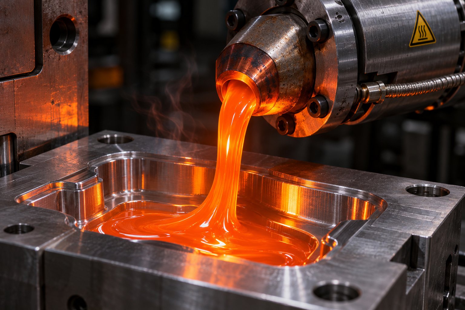
Injection Molding Melt Temperature: Why Your Barrel Settings Lie
Nov 19, 2026
Learn why barrel set points lie about injection molding melt temperature. Complete resin chart, measurement methods, defect troubleshooting, and optimization steps.
Read ArticleLooking for something else?
Search by material, symptom or product and jump straight to the relevant page.
These are navigation suggestions based on keyword matching — not a quotation, not a delivery commitment, and not a substitute for engineering review. Final specification is confirmed by our engineers against your drawings and processed material.
Need help with screw barrel selection?
Share your machine model, processed material and application. Our team can help with pricing and technical support.