

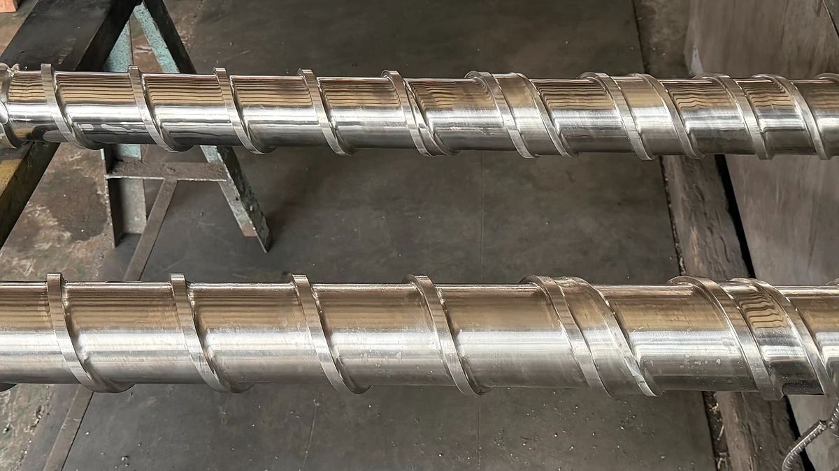
What Is a Single Flight Screw and Why It Matters
Imagine you are specifying a screw for a new conveyor line or replacing the core component inside a plastics extruder. The vendor asks a simple question: single flight or multi-flight? If the distinction feels fuzzy, you are not alone. Despite being the most widely used helical screw geometry in industry, the single flight screw rarely gets a clear, standalone explanation.
A single flight screw is a helical screw featuring one continuous wrap — called a flight — spiraling around a central shaft. Each full rotation advances the flight by exactly one pitch length, creating a single uninterrupted channel between consecutive flight edges. This one-start design is the most fundamental screw geometry used across material handling and plastics processing.
Defining the Single Flight Screw
Picture a core shaft — a solid cylindrical rod — with a single helical ribbon running along its length. That ribbon, either welded onto the shaft or machined directly from bar stock, is the flight. It wraps around the shaft in one continuous spiral, much like the thread on a standard bolt. Between every two neighboring edges of this flight sits an open channel, and that channel is where all the work happens: conveying bulk solids, compressing polymer pellets, or metering molten plastic toward a die.
The term "single flight" specifically means one start. If you look at the end face of the screw, you will see just one flight origin point. A double-start screw, by contrast, would show two origins spaced 180 degrees apart, and a triple-start screw would show three at 120-degree intervals. This distinction matters because the number of starts directly determines the relationship between pitch and lead — for a single-start design, pitch and lead are identical, keeping the geometry straightforward and the conveying behavior predictable.
That simplicity is exactly why this configuration remains the industry default. One channel means maximum open cross-sectional area per revolution, the fewest weld seams during manufacturing, and the lowest production cost for a given screw diameter.
Why This Geometry Matters Across Industries
You will encounter single flight screws in two broad — yet very different — worlds. In material handling, a flight conveyor uses this one-start helical design inside a trough or tube to push grain, cement, chemical powders, or wastewater sludge from one point to another. The single open channel maximizes volumetric capacity, making it the go-to choice for free-flowing and mildly cohesive bulk solids.
In plastics processing, the same fundamental geometry sits at the heart of every single screw extruder. Here, the screw does far more than convey — it compresses, melts, and meters polymer as channel depth changes along the barrel. As one of the most common and economical designs, the single-flighted extruder screw handles the vast majority of standard polymer processing tasks, from polyethylene film to PVC pipe. Extrusion itself plays a dominant role in plastics manufacturing, touching a significant share of all commercial polymer resin before it reaches end users.
Whether you are sizing conveyor flights for a grain elevator or selecting a screw for a single screw extruder, the underlying geometry is the same — and understanding it is the first step toward making the right specification. The sections ahead break down the terminology, compare flight configurations head to head, and walk through the selection criteria you will actually need on the job.
Essential Screw Geometry Terminology Explained
You have seen the words "pitch," "lead," and "flight" scattered across spec sheets and vendor catalogs. They seem interchangeable at first glance — until a miscommunication between your engineering team and a screw manufacturer costs weeks of lead time and thousands of dollars. Precise terminology is the foundation of every accurate screw specification, whether you are ordering a conveyor flight for bulk material handling or a single extruder screw for a plastics line.
The terms below apply equally to screw conveyors and single screw extruder machines, so learning them once equips you for both domains.
Pitch, Lead, and Flight Explained
Pitch is the axial distance between two corresponding points on consecutive flights, measured parallel to the screw's axis. Think of it as the spacing between the crests of the helical blade. As igus notes, this measurement directly influences the screw's conveying performance and compatibility with mating components.
Lead is the axial distance a flight advances in one full rotation of the shaft. Here is the critical distinction: for a single flight screw, pitch and lead are identical because there is only one start. Add a second start, and the lead becomes twice the pitch; add a third, and it triples. This relationship is why single-start designs keep specification simple — you only need one number to describe both values.
Flight refers to the helical blade itself — the raised ribbon wrapping around the core shaft. Flight depth, sometimes called channel depth, is the radial distance from the root of the shaft to the outer tip of the flight. In a single screw extruder machine, channel depth is the single most influential dimension controlling how much material the screw can hold, compress, and pump through each zone.
Two additional diameter terms complete the picture. The root diameter (also called the minor diameter) is the diameter of the central shaft at the base of the channel. The outside diameter (or major diameter) is measured across the outermost tips of the flights. The difference between these two values, divided by two, gives you the flight depth.
How Diameter Ratios Influence Performance
Imagine two screws with the same outside diameter. One has a pitch equal to its diameter — a 1:1 pitch-to-diameter ratio, commonly referred to as a "square pitch." The other has a pitch that is only half its diameter. Which one moves more material per revolution? The square-pitch design does, because each rotation advances material a full diameter length down the axis. That is exactly why the 1:1 ratio is the industry standard for most general-purpose conveyor flights and extruder screws.
Variable pitch designs deliberately break this convention. A screw might start with a longer pitch near the feed opening to pull material in aggressively, then tighten the pitch further down the barrel to compress and pressurize it. This approach is common in extrusion, where the thread pitch is typically set at S = D for the baseline, and any deviation serves a specific processing purpose.
Beyond pitch, the length-to-diameter (L/D) ratio is another specification you will encounter constantly. It describes how long the screw is relative to its diameter. Common L/D values for single extruder screws range from 20:1 to 30:1 and beyond. A higher ratio means more residence time inside the barrel, which generally improves melting uniformity and throughput — but also increases manufacturing cost and the risk of shaft deflection. The compression ratio, defined as the volume of the first feed-zone channel divided by the volume of the last metering-zone channel, rounds out the core specification trio. Together, diameter, L/D, and compression ratio form the shorthand framework engineers use to classify and compare screw designs at a glance.
The table below consolidates these terms into a quick-reference guide you can keep beside any spec sheet.
| Term | Definition | Relevance to Single Flight Screws |
|---|---|---|
| Pitch | Axial distance between corresponding points on consecutive flights | Equal to the lead in a single-start design; typically set at a 1:1 ratio with screw diameter (square pitch) |
| Lead | Axial distance a flight advances in one full shaft rotation | Identical to pitch for single flight screws; diverges only in multi-start configurations |
| Flight | The helical blade wrapped around the core shaft | One continuous flight defines the single-start geometry; it is either machined from solid stock or welded onto the shaft |
| Channel Depth (Flight Depth) | Radial distance from the root diameter to the flight tip | Varies across feed, compression, and metering zones to control conveying volume and pressure generation |
| Root Diameter | Diameter of the central shaft at the channel base | Increases along the screw length in tapered designs to reduce channel depth and compress material |
| Outside Diameter | Diameter measured across the outermost flight tips | Must maintain tight clearance with the barrel bore; wear at the flight tips is a primary maintenance concern |
With these definitions locked in, the natural next question becomes: how does a single flight screw actually stack up against its double- and triple-flight counterparts when real-world performance demands enter the picture?
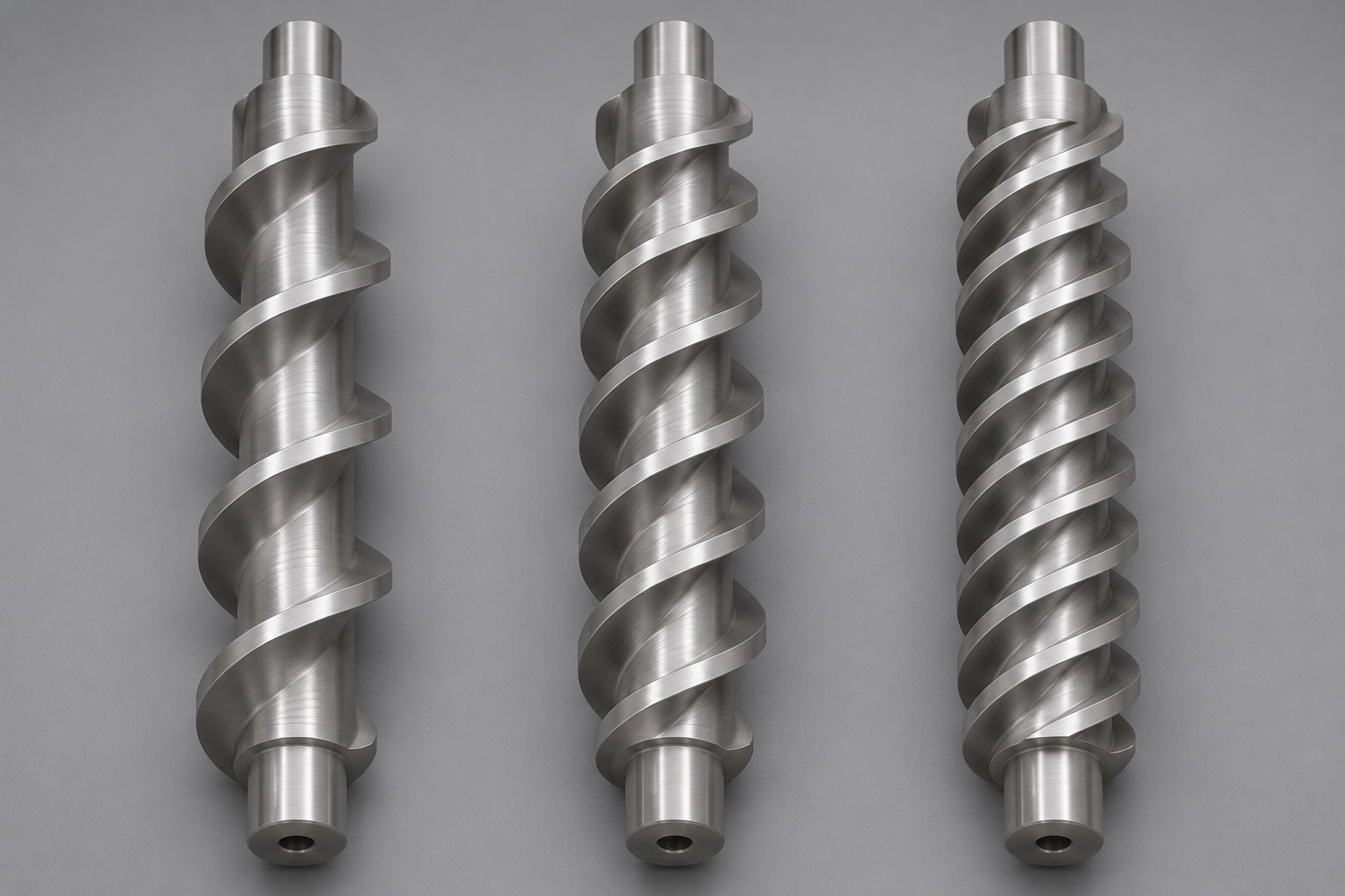
Single Flight vs Multi-Flight Screw Configurations Compared
A single screw with one helical wrap does one job extremely well: it maximizes the open channel volume available for conveying and pressure generation. But what happens when you add a second wrap, or even a third? The answer is not simply "more flights equals better performance." Each additional flight introduces a set of trade-offs that can help or hurt your process depending on the application. Yet a clear, structured comparison across these configurations is surprisingly hard to find.
Let's fix that.
Single Flight vs Double Flight vs Triple Flight
The distinction comes down to the number of helical starts. A single flight screw uses one helical wrap per pitch length — one channel, one flight origin at the screw's end face. A double flight screw introduces a second wrap offset by 180 degrees, creating two interleaved channels. A triple flight screw adds a third wrap at 120-degree intervals, dividing the cross-section into three narrower channels.
Sounds straightforward, but the consequences ripple through every performance metric. Each additional flight subdivides the available channel space, which directly reduces volumetric capacity per revolution. Think of it like cutting a pie into more slices — the total pie is the same, but each individual slice gets smaller. In conveying applications, this effect is quantifiable. Kase Conveyors' engineering guide documents that a cut flight design at 30% loading reduces conveyor capacity by a factor of approximately 1.57 compared to a standard full-flight configuration. Multi-flight designs impose a similar volumetric penalty: the extra flight blade physically occupies channel space and, in many cases, partially blocks the feed opening during rotation.
The penalty doesn't stop at lost volume. As extrusion expert Jim Frankland explains in Plastics Technology, adding a second flight in the feed section of a smooth-bore extruder significantly increases the screw surface area that polymer must slide against. Since solids conveying depends on the material sticking more to the barrel than to the screw, that extra surface area raises frictional drag on the screw side and can actually reduce feed rate against the same down-channel pressure. Attempts to offset this loss — widening the pitch or deepening the channel — introduce their own complications. A longer pitch increases the cross-channel force component, raising friction against the screw surface. A deeper channel allows greater particle slippage, reducing average solid-bed velocity.
So why use double or triple flights at all? Because mixing and material distribution improve substantially. With two or three narrower channels instead of one wide channel, the material is spread more evenly around the screw circumference. This reduces pulsation at the die, improves thermal uniformity in the melt, and provides more consistent pressure distribution. Double flights also offer more bearing surface area for the screw inside the barrel, which lowers localized contact pressure and helps prevent the adhesive wear (galling) that can occur under extreme side loads — a key reason they appear in recycling extruders with side feeders and crammers.
Performance Trade-Offs at a Glance
The table below distills the key differences across all three configurations. Use it as a quick reference when evaluating which geometry fits your process requirements.
| Parameter | Single Flight | Double Flight | Triple Flight |
|---|---|---|---|
| Number of Starts | 1 | 2 (180° apart) | 3 (120° apart) |
| Volumetric Efficiency | Highest — maximum open channel area per revolution | Reduced — second flight occupies channel space and increases screw surface friction | Lowest — three flights further subdivide available volume |
| Mixing Capability | Basic distributive mixing only; relies on channel recirculation | Improved — material spread across two channels enhances thermal and compositional uniformity | Best — three narrow channels maximize material redistribution and reduce temperature gradients |
| Pressure Build-Up | Highest — fewer flight clearances mean fewer leakage paths for backward flow | Moderate — additional clearance gap introduces a second leakage path | Lowest — three clearance gaps allow the most backward leakage under pressure |
| Pulsation at Output | Higher — single channel can produce noticeable output surging | Reduced — two channels deliver material more evenly per rotation | Minimal — three overlapping delivery points smooth output significantly |
| Mechanical Complexity | Simplest — one flight to machine or weld; easiest to manufacture and repair | Moderate — requires precise 180° offset and tighter tolerances | Highest — three interleaved flights demand the most complex manufacturing |
| Typical Applications | Standard conveying, general-purpose extrusion (PE, PP, PS), metering zones, pressure-generating sections | Vented extruder sections, grooved-barrel feed zones, recycling lines with side feeders, barrier sections | High-precision metering for medical tubing, optical film, and heat-sensitive polymers requiring superior melt uniformity |
| Relative Cost | Lowest | Moderate (approximately 20-30% premium) | Highest (significant premium due to machining complexity) |
The pressure build-up advantage of single-flight designs deserves special attention because it stems from a fundamental fluid-mechanics principle. Every flight tip creates a small clearance gap between itself and the barrel wall. Polymer melt — or compressed solids — can leak backward through these gaps, opposing the forward pumping action. Research into leakage-flow models for screw extruders has shown that the volume and direction of this leakage flow are governed by the pressure gradient across the clearance and the shear-thinning nature of the polymer melt. The key takeaway is simple: one flight means one clearance gap per pitch. Two flights double the leakage paths, and three flights triple them. In pressure-generating metering zones — where every drop of backward flow directly reduces net throughput — fewer flights translate to better pumping efficiency.
This is precisely why single-flighted elements remain the standard in metering sections where consistent pressure output matters most, and why multi-flight configurations tend to appear in mixing and venting zones where uniformity takes priority over raw pumping power.
Of course, the screw does not exist in isolation — it operates inside a barrel, interacting with specific materials under specific conditions. The conveying context matters just as much as the flight count, and it shifts dramatically depending on whether you are moving dry bulk solids through a trough or melting polymer pellets inside a heated barrel.
Single Flight Screws in Material Handling and Conveying
Dry bulk solids moving through a trough represent the oldest and most intuitive application for a single flight screw. The concept dates back to the Archimedes screw around 250 B.C., and while materials and manufacturing have evolved dramatically, the core operating principle has not changed: a rotating helical blade pushes material along an enclosed channel from inlet to discharge.
How Single Flight Screws Move Bulk Materials
When the screw turns inside a U-shaped trough or tubular housing, the single continuous flight acts like a moving wall. Material trapped in the open channel between consecutive flight edges is driven forward one pitch length per revolution. Because only one helical blade occupies the cross-section, the remaining open area — the space available for material — is maximized. That is the fundamental advantage of the single-start screw blade configuration in conveying: more room for product means higher volumetric capacity at a given screw speed.
Beyond capacity, the single flight design offers several practical benefits that keep it as the industry default for standard horizontal and slight-incline conveying:
- Simplest manufacturing — one flight to form, fit, and weld reduces fabrication time and cost
- Lowest purchase price — fewer welds and less material translate directly into budget savings
- Easy maintenance — a single helical path is straightforward to inspect, clean, and repair
- Best fit for free-flowing and mildly cohesive materials — powders, granules, and pellets that do not require aggressive mixing move efficiently through one wide channel
For most standard-pitch screw conveyors, the pitch equals the screw diameter — the same square-pitch convention discussed earlier. This 1:1 ratio provides reliable, predictable throughput without the complexity of variable-pitch or multi-flight alternatives. Short-pitch versions, where the pitch drops to roughly two-thirds of the diameter, come into play for inclined or vertical conveying where material rollback becomes a concern. Either way, the single screw extrusion of bulk solids through a trough relies on the same one-start geometry.
Sectional vs Helicoid Flight Manufacturing
How is that helical blade actually made? Two dominant methods exist, and the choice between them affects cost, durability, customization options, and field serviceability.
Helicoid flights are formed from a continuous steel strip that is cold-rolled into a helix in one unbroken length. The rolling process is fast, generates minimal scrap, and produces a flight that is thicker at its inner edge and tapers toward the outer edge. That outer edge hardens during manufacturing, providing improved resistance to abrasive products. Once formed, the helicoid strip is mounted onto a center pipe and secured with skip welds. You will notice fewer weld seams overall, which creates a smoother conveying surface — less product hangup, less contamination risk, and easier cleaning. The trade-off is limited customization: helicoid rolling machines constrain diameter, thickness, and pitch to standard CEMA sizes.
Sectional flights take a different approach. Individual steel discs are cut, pressed into helical segments — typically one revolution per piece — and then welded onto the center pipe. This method demands more labor and welding skill, making it more expensive. However, it opens the door to greater design flexibility: custom thicknesses, specialty alloy materials, and non-standard pitch configurations are all achievable. Sectional flights also feature uniform thickness from inner edge to outer edge, which gives them an advantage in heavy-duty, high-abrasion environments. When a section wears out, a maintenance crew can cut it away and weld on a replacement without scrapping the entire screw assembly — a major benefit for field repair in remote or continuous-operation facilities.
So how do you choose? A practical rule of thumb: helicoid flights are the cost-effective default for lightweight to moderately abrasive materials where standard sizes suffice. Sectional flights earn their premium when the application involves heavy abrasive loads, requires non-standard dimensions, or demands the ability to swap individual worn sections during scheduled maintenance windows.
Across both manufacturing methods, single flight conveyors serve an impressively wide range of industries. Typical bulk material applications include:
- Grain handling — wheat, corn, rice, and soybeans in agricultural elevators and processing plants
- Cement transport — moving powdered or granulated cement between silos, mixers, and packaging lines
- Wastewater processing — conveying dewatered sludge, screenings, and grit in municipal and industrial treatment facilities
- Chemical powder conveying — transferring fertilizers, pigments, calcium carbonate, and other fine chemical solids
- Food-grade material movement — sugar, flour, spices, and animal feed in sanitary stainless-steel trough or tubular systems
Each of these applications benefits from the single flight screw's combination of maximum channel volume, simple construction, and straightforward maintenance. The geometry is so well suited to standard conveying that it remains the starting point for virtually every screw conveyor specification — multi-flight, cut-flight, and ribbon designs enter the conversation only when mixing, anti-clogging, or specialty handling requirements justify the added complexity.
Material handling, however, tells only half the story. The same one-start helical geometry sits at the core of plastics extrusion — but there, the single flight screw does far more than push solids from point A to point B. It compresses, melts, and meters polymer through distinct thermal and mechanical zones, each placing very different demands on flight depth, pitch, and surface treatment.
Single Flight Screws in Plastic Extrusion Machines
Pushing grain through a trough is one thing. Transforming solid plastic pellets into a perfectly homogeneous molten stream — while simultaneously conveying, compressing, and pressurizing them through a heated barrel — is an entirely different engineering challenge. Yet at the heart of that challenge sits the exact same geometry: a single helical screw flight wrapped around a central shaft.
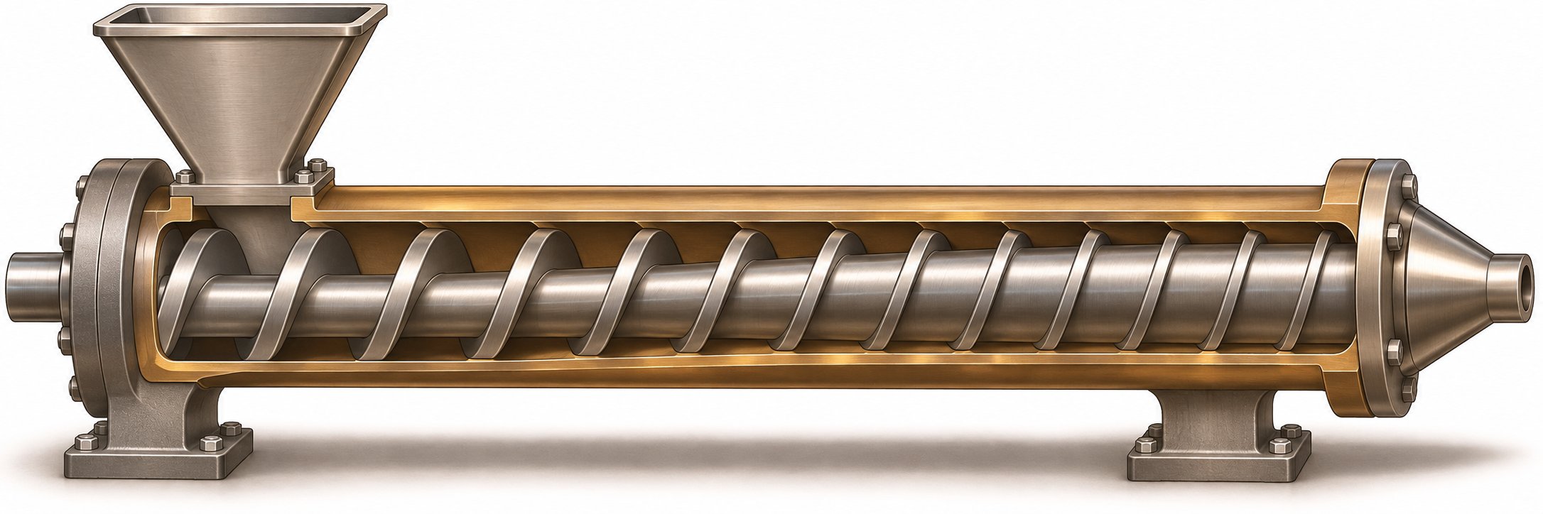
In a single screw extruder, the screw is not merely a conveyor. It is the primary functional component responsible for three distinct tasks: feeding solid polymer pellets, melting them through a combination of shear heat and barrel conduction, and metering the resulting melt at consistent pressure toward the die. The vast majority of conventional extruder screws rely on a single-start flight design along their entire working length. This one continuous helical channel — spiraling from the feed throat all the way to the screw tip — is where the entire transformation from raw pellet to processable melt takes place.
The Role of Single Flight Geometry in Extrusion
Why does single screw extruder design overwhelmingly favor one flight rather than two or three? The answer loops back to the pressure and volumetric advantages covered earlier. A single flight creates one unbroken channel with maximum cross-sectional area. That wide-open channel pulls in the most material per revolution at the feed end and, critically, provides the fewest leakage paths at the metering end where pressure generation matters most.
But here is where extrusion screw flight geometry diverges sharply from conveyor design: the channel depth is not constant. Instead, it changes deliberately along the screw's length to accomplish different processing objectives in different zones. Imagine unrolling the helical channel and laying it flat. Near the feed end, the channel is deep — a wide-open trench designed to swallow as many pellets as possible. As you move downstream, the floor of that trench gradually rises, squeezing the material into a progressively tighter space. By the time you reach the discharge end, the channel is shallow and uniform, acting more like a precision pump than a bulk conveyor.
This controlled variation in channel depth is what transforms a simple screw flight into a complete polymer processing system. Each section of the screw has a name, a purpose, and a distinct set of design rules — collectively known as the three classical zones.
Feed, Compression, and Metering Zones
Every standard single-flight extruder screw divides into three functional regions. As veteran extrusion engineer Allan Griff details in his Plastics Extrusion Operating Manual, a standard screw follows this three-zone architecture, with most designs using a square pitch (pitch equal to diameter) so that the L/D ratio can be quickly estimated by counting turns. Here is how each zone works and how the single flight screw is optimized within it:
- Feed Zone — This is the intake section directly beneath the hopper opening. Channel depth here is constant and relatively deep — deep enough to accept a steady supply of solid pellets or powder. The screw flights in this zone function much like they would in a material handling conveyor: they grab incoming solids and push them forward. Successful feeding depends on the pellets gripping the barrel wall more than the screw root, so the barrel surface is often roughened or grooved while the screw root may be polished or chrome-plated to encourage slip. The deep channel maximizes volumetric intake, and the constant depth avoids premature compression that could bridge or jam incoming material.
- Compression (Transition) Zone — As material advances past the feed section, the channel depth progressively decreases. The root diameter of the shaft gradually increases, and the walls of the channel effectively "close in" on the plastic. This compression serves two vital purposes. First, it squeezes out trapped air between the pellets, preventing bubbles in the final product. Second, it forces solid particles into tighter contact with each other and with the heated barrel wall, dramatically accelerating melting through a combination of conducted heat and frictional (shear) energy. The screw flights here are tapered — each successive turn is slightly shallower than the last. Getting this taper right is critical: too aggressive a compression and the solid bed jams; too gentle and melting is incomplete by the time material reaches the next zone.
- Metering Zone — By this point, the polymer is nearly or fully molten. The channel depth becomes constant again, but much shallower than the feed section. This shallow, uniform channel acts as a precision pump, homogenizing the melt temperature and building the consistent pressure needed to push material through screen packs, adapters, and the die. The compression ratio of the screw — the ratio of feed-zone channel volume to metering-zone channel volume — typically falls between 2:1 and 4:1, depending on the polymer being processed. Shallow screw flights in this zone also increase shear rate, which helps blend any remaining temperature or compositional variations in the melt.
Notice how the single flight screw does something no conveyor screw needs to: it changes its effective geometry along its own length. The flight itself maintains the same outside diameter from end to end (it must, to maintain clearance with the barrel bore), but the root diameter beneath it rises steadily through the compression zone. The result is a single helical channel that starts deep and wide, narrows progressively, and finishes shallow and tight — all in one continuous piece of steel.
The most common L/D ratio for these screws sits around 24:1, though longer ratios of 30:1 or more are used when additional melting capacity, mixing time, or throughput is needed. Flight width — the thickness of the helical blade measured along the screw axis — is typically about 10% of the barrel diameter. Go much wider and you waste usable screw length while generating excessive heat in the flight-tip clearance zone. Go narrower and you risk too much backward leakage through that clearance, undermining the metering zone's pumping efficiency.
This three-zone architecture is remarkably versatile. It handles everything from commodity polyethylene and polypropylene to engineering resins like nylon and polycarbonate — with adjustments to compression ratio, zone lengths, and channel depths tailored to each polymer's melting behavior and viscosity profile. Yet for all its versatility, the standard three-zone single flight screw has limits. Heat-sensitive polymers can degrade before they fully melt. Hygroscopic resins absorb moisture that creates bubbles and surface defects. Highly filled compounds demand mixing intensity that a simple helical channel cannot deliver alone.
These limitations have driven the development of specialized designs — barrier flights, vent sections, grooved-feed pairings, and variable-pitch configurations — that build directly on the single-flight platform without abandoning its fundamental one-start architecture.
Advanced Single Flight Screw Designs for Extrusion
The standard three-zone screw handles an impressive range of polymers — but "handles" and "optimizes" are two very different words. When a processor pushes throughput higher, switches to a moisture-sensitive resin, or begins running abrasive glass-filled compounds, the limitations of a basic single flight screw surface quickly. The good news? Engineers have spent decades refining that same one-start architecture into specialized variants that solve specific processing problems without abandoning the fundamental geometry.
Each design described below is still, at its core, a single flight screw. The helical channel remains the primary conveying and pressurizing mechanism. What changes is how that channel is subdivided, interrupted, or reshaped at key points along its length to improve melting efficiency, remove volatiles, or control compression more precisely.
Barrier and Vented Single Flight Designs
If you have ever pulled a screw and found unmelted pellets embedded in the final product, you have seen the problem that barrier screw design single flight variants were invented to solve. In a conventional three-zone screw, the solid bed and the growing melt pool share the same channel. As melting progresses through the compression zone, a thin melt film forms along the barrel wall while an increasingly unstable wedge of unmelted pellets rides along the screw root. At some point, that solid wedge can break apart — a phenomenon called solid-bed breakup — sending chunks of unmelted polymer downstream into the metering zone and, ultimately, into the die.
A barrier screw prevents this by introducing a secondary, undercut flight within the transition zone. This secondary flight — sometimes called the barrier flight — runs parallel to the primary flight but sits slightly below the barrel bore, leaving a controlled clearance gap. That gap is large enough for molten polymer to cross over but too tight for unmelted pellets to pass through. The result is two distinct sub-channels: a solids channel that retains the diminishing solid bed and a melt channel that collects the growing volume of molten polymer. Research by Kazmer (2020) confirms this architecture, describing how the barrier screw uses a secondary flight beginning in the transition zone to separate the melted polymer adjacent to the primary flight from the unmelted pellets, thereby avoiding a large melt zone in the primary channel that would slow efficient melting. At the end of the transition section, a full circumferential barrier guarantees that only fully plasticated material enters the metering zone.
The beauty of this approach is that the primary flight — the single-start helix — still does the heavy lifting. It conveys, compresses, and meters. The barrier flight is simply an intelligent addition that keeps the solid and liquid phases from interfering with each other during the most thermally chaotic section of the screw. Output consistency improves, melt temperature becomes more uniform, and the risk of unmelted gels reaching the die drops dramatically.
Vented extruder screw configurations tackle a completely different problem: trapped moisture and volatiles. When you process hygroscopic resins like nylon (PA), polycarbonate (PC), or recycled materials with residual contaminants, moisture locked inside the pellets vaporizes during melting. Without an escape route, that vapor creates bubbles, splay marks, and degraded mechanical properties in the finished product. Pre-drying helps, but it adds energy cost, floor space, and process time — and for some recycled feedstocks, drying alone is insufficient.
A vented screw solves this by operating as a two-stage (or even three-stage) design on a single shaft. The first stage functions like a conventional single flight screw — feeding, compressing, and melting the polymer. A mixing element at the end of this first stage ensures complete melting before the material reaches the vent section. Then comes the critical feature: a sudden increase in channel depth that drops melt pressure to atmospheric levels. This decompression zone sits directly beneath a vent port machined into the barrel, allowing steam, volatiles, and trapped air to escape freely. The second stage picks up where the first left off, re-compressing and metering the now-degassed melt toward the die.
Sounds straightforward, but the engineering details matter enormously. The second-stage metering section must have a higher pumping capacity than the first stage to prevent molten polymer from backing up and flooding the vent port. The vent section's channel depth must be deep enough that the melt only partially fills the channel, maintaining atmospheric exposure. And the overall L/D ratio must increase — typically to 30:1 or longer — to accommodate the extra decompression and re-pressurization length. In special cases, three-stage screws with two vent ports can be used for materials that require even more aggressive degassing.
Grooved Feed Sections and Variable Pitch Configurations
Imagine dropping polymer pellets into a hopper and watching them spin uselessly with the screw instead of feeding forward. This happens when friction between the pellets and the screw surface is too high relative to friction between the pellets and the barrel wall. Grooved feed barrels were developed specifically to tip this friction balance in favor of forward conveying.
The concept is elegantly simple: machine a series of longitudinal or helical grooves into the barrel's inner surface directly beneath the feed opening. Pellets wedge into these grooves, anchoring themselves against the barrel wall so they cannot co-rotate with the screw. The single flight screw then acts purely as a positive-displacement pump in the feed zone, pushing material forward with each revolution rather than merely tumbling it. Experimental research by Johann et al. (2022) confirmed this behavior across multiple polymer types and granule geometries, demonstrating that grooved feed zones produce throughput that is essentially independent of downstream die pressure — a stark contrast to smooth-bore systems where back pressure directly reduces output. Their study also found that the mass throughput of an entire grooved-barrel extruder closely matched the throughput of the isolated grooved feed zone, confirming that the feed section truly governs the process.
Pairing a grooved feed barrel with a single flight screw requires careful attention to screw design. Because the grooves force-feed material so aggressively, the compression zone must be long enough and gradual enough to handle the increased solids pressure without jamming. Screw designers often reduce the compression ratio or lengthen the transition zone to accommodate the higher feed rates that grooved barrels deliver.
Variable pitch flight manufacturing takes a different route to controlling compression and throughput. Instead of changing channel depth alone, the pitch itself — the axial spacing between flight edges — varies along the screw length. A wider pitch near the feed opening pulls material in quickly, while a tighter pitch downstream compresses it more aggressively. Alternatively, the pitch may increase toward the discharge end to provide decompression, useful in vented designs or when processing shear-sensitive materials.
This is not a separate screw type. It is a modification of the same single-start architecture, adjusting one geometric parameter — the helix angle — to fine-tune how material accelerates, compresses, or relaxes at specific points along the barrel. Variable pitch designs are common in variable pitch screw conveyors as well, where they prevent flood feeding at the inlet and ensure even material distribution along the trough.
The key takeaway across all of these variants is that none of them abandon the single flight platform. They enhance it. The primary helical channel remains the workhorse, and each specialized feature — barrier flight, vent section, grooved-barrel pairing, or pitch variation — addresses a specific limitation of the basic design. Here is a summary of the primary specialized configurations built on single-start geometry:
- Barrier screws — secondary undercut flight separates solids from melt in the transition zone, improving melting efficiency and eliminating unmelted gels
- Vented screws — two-stage or three-stage designs with decompression zones and barrel vent ports for removing moisture and volatiles mid-process
- Grooved-feed-optimized screws — designed with adjusted compression ratios and transition lengths to pair with grooved barrels for pressure-independent, high-rate solids conveying
- Variable-pitch screws — helix angle changes along the screw length to control compression rate, decompression, and material intake independently of channel depth
- Mixing-element-equipped single-flight screws — standard single-start screws fitted with distributive or dispersive mixing sections (pins, fluted mixers, or pineapple-style elements) at strategic locations to break up flow patterns and improve melt homogeneity
Matching the right configuration to the target polymer and production requirement is essential. A barrier design that works beautifully for LDPE film may be completely wrong for a vented nylon compounding line, and a grooved-feed setup optimized for HDPE pipe extrusion may overpower the compression zone when processing a low-bulk-density regrind. Engineering consultation — ideally with a screw manufacturer that offers barrier, vented, single-start, multi-start, and grooved-feeding configurations alongside nitrided and specialty surface treatments — is the most reliable path to a design that fits your specific material, machine, and throughput targets. NANHAIYA's single screw barrel product line, for example, covers this full range of configurations for both custom and replacement manufacturing, though confirming specific flight geometry, vent-port details, and machine compatibility through direct technical discussion is always recommended.
Choosing the right specialized design is only half the equation. Even the most sophisticated screw geometry degrades over time — and understanding how and where a single flight screw wears is the difference between a scheduled rebuild and an expensive emergency shutdown.
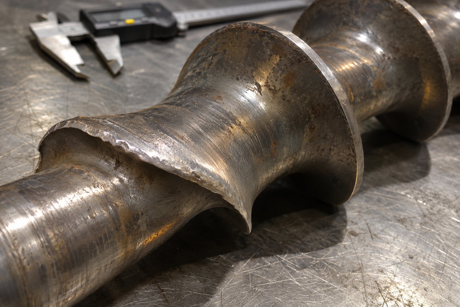
Wear Patterns and Troubleshooting for Single Flight Screws
A well-chosen screw design means nothing if it grinds itself into obsolescence inside the barrel. Every single flight screw — whether it conveys grain through a trough or meters molten polyethylene toward a die — is in a constant battle against wear. The forces that make it effective at moving material are the same forces that gradually destroy it. Understanding where and how that destruction happens is the key to single screw extruder troubleshooting that prevents minor degradation from snowballing into a production crisis.
Common Wear Patterns in Single Flight Screws
Three primary mechanisms attack screw surfaces, often working in combination rather than isolation.
Abrasive wear is the most common culprit. Hard particles — glass fibers, mineral fillers like calcium carbonate, wood flour, or even metal contaminants in recycled feedstock — act like sandpaper against the flight surfaces and barrel wall with every revolution. Glass fibers, with a Mohs hardness near 6.5, are among the most aggressive. Analysis by Spalding and Womer confirms that abrasive fillers cause especially high wear rates in zones with high solids content, where unmelted particles grind directly against metal surfaces under substantial pressure.
Adhesive wear occurs when the thin polymer film separating the flight tip from the barrel bore is lost. Without that lubricating melt layer, metal contacts metal directly. Microscopic welds form and tear apart at every contact point — a destructive cycle known as galling. Poor barrel alignment, polymer starvation during startup, or solids wedging in the compression zone can all push the screw against one side of the bore and trigger rapid, localized damage that looks dramatically different from the smooth, gradual erosion caused by abrasion.
Corrosive wear attacks through chemistry. Resins like PVC release hydrochloric acid at processing temperatures; fluoropolymers emit hydrofluoric acid. These byproducts chemically etch flight surfaces, creating rough, pitted textures that trap degraded polymer and weaken the metal's resistance to subsequent mechanical removal.
Here is the detail that matters specifically for single-start designs: because only one flight edge exists per pitch length, all conveying force concentrates along that single helical path. In a double or triple flight configuration, the same load distributes across two or three flight tips. A single flight screw, by contrast, asks one edge to do all the work — meaning wear along that edge can be more intense and more localized. You will often see the leading face of the flight and the outermost tip worn far more heavily than the trailing face, especially in the compression zone where pressure peaks and partially melted abrasive particles exert maximum force.
Signs of Wear and When to Replace or Refurbish
Wear rarely announces itself with a single dramatic failure. Instead, it sends a series of increasingly urgent signals through your production data and finished product quality. Recognizing these screw flight wear indicators early gives you time to plan a rebuild or replacement during a scheduled maintenance window — rather than scrambling after an emergency shutdown.
Watch for these warning signs that indicate a single flight screw needs inspection:
- Declining output rates at constant screw speed — the widening flight clearance allows material to leak backward over the flight tips instead of advancing toward the die, reducing net forward flow
- Increased motor amperage — the drive works harder to compensate for lost pumping efficiency, drawing more current for the same or lower throughput
- Poor melt homogeneity — uneven temperature distribution, unmelted gels, or streaks in the extrudate point to a metering zone that can no longer maintain consistent pressure and shear
- Visible flight clearance increase — when you pull the screw and measure the outside diameter of the flight tips, any reduction beyond the original tolerance (typically the nominal diameter divided by 1,000, per side) represents wear that directly impacts performance
- Surface pitting or scoring — rough patches, directional grooves, or cratered surfaces on flight faces indicate active abrasive, adhesive, or corrosive attack
As a practical benchmark, industry guidelines suggest considering screw replacement when flight clearance reaches roughly four times the clearance when new — though critical applications like medical tubing may demand action at just twice the original clearance. A screw should never be refurbished more than three times, because repeated hardfacing cycles degrade the base metal and increase the risk of delamination between the hard overlay and the substrate.
Speaking of hardfacing screw flights: this is both a preventive and a restorative measure. The process involves welding wear-resistant alloys — typically chromium carbide, tungsten carbide, or cobalt-based compositions — onto flight tips and leading edges. A well-applied hardfacing layer dramatically extends service life in abrasive environments by placing a sacrificial shield of hard material exactly where contact forces are greatest. The choice of alloy matters: chromium carbide overlays perform well in standard abrasion applications, while tungsten carbide hardfacing provides superior resistance against the most aggressive fillers. Critically, hardness alone does not guarantee performance — the carbide structure, distribution, and toughness of the overlay must match the actual wear mechanism in play.
Nitrided surfaces offer a complementary defense. Gas nitriding diffuses nitrogen into the screw's steel surface, creating a hardened case (typically 65-70 HRC) that resists both wear and corrosion. While the nitrided layer is relatively thin — roughly 0.4 to 0.6 mm — it provides an effective baseline protection for screws processing unfilled or lightly filled polymers and adds corrosion resistance that bare steel cannot offer.
The most effective maintenance strategy combines both approaches: nitriding the screw body for general surface protection and applying hardfacing specifically to flight tips and leading edges where mechanical wear concentrates. Early detection through scheduled measurement of flight outside diameter and channel depth at regular intervals — every three to six months for abrasive compounds, every twelve to eighteen months for clean resins — prevents the kind of unplanned downtime that costs far more than any rebuild.
Recognizing wear is essential, but it only answers the question of when to act. The equally important question — whether to stick with a single flight configuration or switch to a multi-flight alternative — depends on matching the screw design to your specific material, throughput, and quality requirements.
Choosing the Right Screw Flight Configuration
You have seen the geometry, the terminology, the wear patterns, and the specialized designs. But all of that knowledge converges on a single practical question: should you specify a single flight screw for your application, or does your process demand a double, triple, or otherwise specialized configuration? Too many engineers default to what they have always used — or worse, overbuild with multi-flight designs that sound impressive on paper but actually hurt throughput and pressure performance in practice.
The screw flight configuration selection process does not need to be that complicated. It comes down to understanding what your application truly demands and then matching geometry to those demands — not the other way around.
When Single Flight Is the Right Choice
A single-start design is not just the cheapest or simplest option. In many scenarios, it is objectively the best-performing one. Here is when it earns that distinction:
Maximum volumetric throughput in conveyors. If you are moving free-flowing or mildly cohesive bulk solids — grain, cement, chemical powders, food ingredients — through a horizontal or slightly inclined trough, a single flight screw delivers the highest possible volume per revolution. There is no second or third blade eating into your channel space. For standard-pitch screw conveyors operating at typical loading percentages of 15% to 45%, as recommended by screw conveyor engineering guidelines, the one-start geometry is the uncontested default.
Standard polymer extrusion with adequate mixing. Commodity resins like PE, PP, and PS melt predictably and do not require aggressive mixing beyond what a well-designed three-zone screw provides. A single screw extruder for PP PE processing, equipped with appropriate compression ratios and zone lengths, delivers consistent melt quality without the volumetric penalty of additional flights. As the research from Paderborn University's extrusion studies demonstrates, a properly designed three-section single-flight screw achieves thermal and material homogeneity that correlates closely with high screw performance index values — the quantitative measure of overall melt quality.
High pressure generation with minimal leakage flow. This is the engineering principle that gives the single-start design its most decisive advantage in metering zones and pressure-critical sections. Every flight tip creates a clearance gap between itself and the barrel bore. Polymer melt under pressure leaks backward through that gap, opposing the screw's forward pumping action. One flight means one gap per pitch. Double the flights, and you double the leakage paths. In metering zones where net forward flow directly determines output rate — and where even small backward losses multiply across dozens of turns — fewer flights translate to measurably better pumping efficiency.
Cost-sensitive applications. When budgets are tight and the process does not demand specialized mixing or reduced pulsation, the single flight screw's lower manufacturing cost provides a real advantage. One flight to machine or weld, simpler tolerances, faster production, and easier field repair all contribute to a lower total cost of ownership.
When to Consider Multi-Flight or Specialized Alternatives
The single flight vs double flight screw debate only becomes interesting when specific process demands push beyond what one helical channel can deliver on its own. Here are the situations where adding flights — or switching to a specialized geometry — genuinely pays off:
Heat-sensitive materials requiring gentle, distributed mixing. Polymers like PVC rigid compounds, certain bioplastics, and thermally sensitive elastomers degrade when exposed to the intense localized shear that can occur in a single deep channel. Double or triple flights spread the material into narrower, shallower sub-channels, reducing peak shear rates and distributing heat more evenly. The trade-off in throughput is justified by the preservation of material properties.
Severe pulsation concerns. Single-start screws inherently deliver material in one "slug" per revolution, which can produce noticeable pressure and flow surging at the die. For applications like thin-wall medical tubing or optical-quality film, where dimensional tolerances are measured in microns, multi-flight designs smooth the delivery by providing two or three overlapping pulses per revolution. The result is more consistent wall thickness and fewer out-of-spec rejects.
Superior melt homogeneity requirements. When processing highly filled compounds or color-critical products, a single channel may not redistribute material effectively enough to eliminate temperature gradients and compositional streaks. NC State Extension's screw profile design guide emphasizes that mixing capability is fundamentally tied to how many times the flow is divided and recombined — and multiple flights inherently create more flow-splitting opportunities per revolution than a single channel alone.
Recycling and side-fed extruders. Lines with side feeders or crammer units impose asymmetric side loads on the screw. A double flight provides additional bearing surface that resists deflection and distributes contact pressure more evenly against the barrel bore, reducing the risk of adhesive wear (galling) that single-flight screws face under extreme lateral forces.
The decision matrix below translates these principles into specific application scenarios. Use it as a starting point for specification discussions with your screw vendor or engineering team.
| Application Requirement | Recommended Configuration | Rationale |
|---|---|---|
| Standard PE/PP film or pipe extrusion | Single flight, three-zone or barrier design | Maximizes throughput and pressure generation; commodity resins melt predictably without aggressive mixing; barrier variant prevents solid-bed breakup at higher speeds |
| Abrasive glass-filled or mineral-filled compounds | Single flight with hardfaced flight tips; barrier design for high throughput | Minimizes leakage paths (fewer clearance gaps wearing under abrasive load); hardfacing protects the single critical flight edge where wear concentrates |
| Moisture-sensitive polymers (nylon, PC, recycled PET) | Single flight, two-stage vented design | Decompression zone and vent port remove volatiles mid-process; single-start geometry maintains high pumping efficiency in both first and second metering stages |
| High-throughput bulk conveying (grain, cement, powders) | Single flight, standard pitch, helicoid or sectional construction | One-start design provides maximum open channel area per revolution; simplest and most cost-effective manufacturing for standard CEMA sizes |
| Precision medical tubing or optical film | Triple flight metering section (often paired with single-flight feed and compression zones) | Three overlapping delivery points minimize output pulsation; narrow sub-channels improve thermal uniformity critical for tight dimensional tolerances |
| Rigid PVC or thermally sensitive elastomers | Double flight with reduced compression ratio | Two narrower channels distribute shear more evenly, lowering peak melt temperatures and reducing risk of thermal degradation |
| Recycling lines with crammer or side feeder | Double flight in feed zone; single flight in metering zone | Double flight resists lateral deflection from asymmetric side loading; single flight in metering section preserves pressure-building efficiency |
Notice a pattern in the table? Several of the most demanding applications use hybrid configurations — a single-start geometry where it matters most for pressure and throughput, with multi-flight sections added only in zones where mixing or pulsation control justifies the volumetric cost. This is not an accident. It reflects the core engineering principle behind screw flight configuration selection:
Choose a single flight design for maximum conveying efficiency and pressure generation, and add flights only when mixing, pulsation, or material uniformity demands clearly justify the volumetric trade-off.
That principle applies whether you are sizing a screw conveyor for a cement plant or specifying a replacement barrel and screw set for a single screw extruder. Start with one flight. Add complexity only when the material, the product specification, or the process data tell you the single-start design is not enough — and even then, add it surgically, in the zone where the limitation actually exists, rather than across the entire screw length.
With the right configuration selected, the final step is equally practical: translating your design decision into a specification that a manufacturer can actually build. That means nailing down diameters, L/D ratios, compression ratios, materials of construction, and surface treatments — a process where missing even one dimension can send you back to square one.
Sourcing and Specifying Single Flight Screws
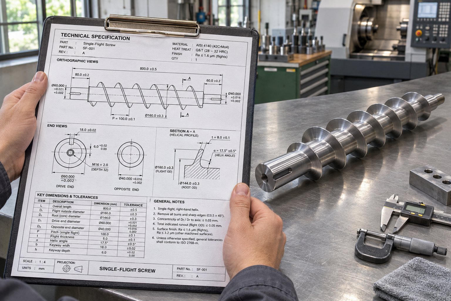
You have selected the right flight configuration, identified the wear profile your application demands, and decided whether a standard three-zone design or a specialized barrier or vented variant fits your process. All of that engineering clarity evaporates the moment you sit down to write a purchase order — unless you can translate your design decisions into a complete, unambiguous set of single flight screw specifications that a manufacturer can quote, build, and deliver without a single round of "what did you mean by that?" revisions.
Whether you are ordering a single screw barrel replacement for an aging extruder or specifying new components for a machine build, the information you provide upfront determines the accuracy of the quote, the speed of production, and the likelihood that the finished screw drops into your barrel and performs exactly as expected on the first run.
Key Specifications for Ordering a Single Flight Screw
Imagine handing a machinist a napkin sketch and asking for a precision component. That is essentially what happens when a buyer submits a quote request missing critical dimensions. Every serious screw manufacturer needs a consistent set of parameters to generate a meaningful price and a buildable drawing. Here is the specification checklist you should assemble before contacting any supplier:
- Screw diameter (nominal bore size) — the non-negotiable starting point, locked by your machine's barrel bore specification. Measure it physically if documentation is unavailable.
- L/D ratio or total flighted length — determines overall screw length and directly impacts material cost, machining time, and straightness tolerances. Common values range from 24:1 to 36:1 for extrusion applications.
- Flight depth per zone — specify the channel depth in the feed, compression (transition), and metering sections individually. These values define the screw's conveying volume, compression behavior, and metering precision.
- Pitch (and any variable-pitch transitions) — standard square pitch (1:1 with diameter) is the default, but note any sections where pitch changes to control intake rate or decompression.
- Compression ratio — the ratio of feed-zone channel volume to metering-zone channel volume, typically between 2:1 and 4:1 depending on the polymer being processed.
- Number of flights (starts) — confirm single-start for the entire length, or specify if certain zones (e.g., the metering section) require double or triple flights.
- Special features — barrier flights, vent sections, mixing elements, grooved-feed optimization, or any non-standard geometry that deviates from a basic three-zone profile.
- Material of construction — the steel grade or alloy specification for the screw body (e.g., 38CrMoAlA, 4140, tool steel, or bimetallic substrate).
- Surface treatment — nitriding depth and hardness, hardfacing alloy and locations, chrome plating, or other coatings.
- Machine make and model — allows the manufacturer to cross-reference known barrel dimensions, drive spline configurations, and shank geometry.
- Polymer and filler type — informs metallurgy recommendations and helps the manufacturer flag potential design mismatches before production begins.
Missing even one of these items forces the manufacturer to guess — and guesses become expensive mistakes when the finished screw arrives on your dock with the wrong compression ratio or an incompatible shank profile. If you are replacing an existing screw, the simplest approach is to send the worn component to the manufacturer for reverse engineering. They can measure every dimension, identify the original design intent, and recommend improvements based on the wear patterns they observe.
For new-build projects, provide as much process data as you can: target throughput rate, operating temperature range, die pressure requirements, and any known processing challenges with your resin. This information enables the manufacturer's engineering team to validate your specification — or suggest adjustments that improve performance before a single dollar is spent on steel.
Material and Surface Treatment Options
The steel beneath the flights and the treatment applied to its surface are where long-term economics play out. Choose too soft a material for an abrasive application, and you will replace the screw in a fraction of its expected life. Over-specify metallurgy for a gentle commodity resin, and you burn budget without gaining any measurable benefit.
Here is how the most common options align with real-world processing conditions:
Nitrided alloy steel remains the workhorse for general-purpose extrusion. Gas or plasma nitriding creates a hardened surface layer — typically 0.3 to 0.6 mm deep at 65-70 HRC — that resists adhesive and mild abrasive wear while the tougher core absorbs torsional loads. For processors running unfilled PE, PP, PS, or general-purpose ABS, a nitrided extruder screw surface treatment delivers solid performance at the lowest acquisition cost. Service life in these gentle environments typically spans three to five years of continuous operation.
Bimetallic alloys step in when nitriding cannot keep pace. A wear-resistant alloy layer — often nickel-chromium-boron compositions — is metallurgically bonded to the steel substrate, providing 1.5 to 3.0 mm of usable wear depth compared to the 0.4 to 0.6 mm of a nitrided case. That additional depth translates directly into extended service intervals. Documented comparisons show bimetallic assemblies lasting two to three times longer than nitrided equivalents in abrasive applications, with wear rates reduced by over 60%. Glass-fiber-reinforced nylons, mineral-filled masterbatch, and contaminated recycled feedstock all justify the premium.
Tool steels with enhanced hardening occupy the middle ground. Grades like CPM9-V or D2 accept deeper case hardening and maintain hardness at elevated temperatures, making them suitable for moderately abrasive polymers where standard nitriding falls short but full bimetallic construction feels like overkill.
Specialty coatings and hardfacing overlays — tungsten carbide, chromium carbide, hard chrome plating, and plasma-transferred arc (PTA) alloy spraying — sit at the top of the cost and performance hierarchy. Surface hardness in the HRC 58-65 range delivers maximum resistance against both abrasive wear and chemical corrosion, targeting the most punishing applications: highly filled engineering resins, corrosive PVC formulations, and recycled streams with unpredictable contaminants.
PVC-specific considerations deserve a separate mention. PVC releases hydrochloric acid during thermal degradation, which attacks nitrided surfaces aggressively while barely marking corrosion-resistant bimetallic liners. Processors running rigid PVC formulations at high temperatures should specify corrosion-resistant alloy construction or hard-chrome plating as a baseline — not an upgrade.
The table below maps common processing scenarios to the metallurgy tier that delivers the best balance of performance and cost:
| Processing Scenario | Recommended Material / Treatment | Why It Fits |
|---|---|---|
| Unfilled PE, PP, PS, ABS | Standard nitrided alloy steel (e.g., 38CrMoAlA / 4140) | Gentle wear environment; nitrided case provides adequate protection at lowest cost |
| Lightly filled compounds (talc, CaCO3 under 20%) | Deep-nitrided alloy or mid-range tool steel | Moderate abrasion exceeds standard nitriding limits but does not justify full bimetallic cost |
| Glass-fiber-reinforced nylon or PBT | Bimetallic alloy with hardfaced flight tips | Glass fibers (6.5 Mohs) destroy nitrided cases rapidly; 1.5-3.0 mm alloy depth provides economical service life |
| Recycled plastics with metal or mineral contaminants | Bimetallic or tungsten carbide overlay | Unpredictable abrasive load demands maximum wear depth and hardness |
| PVC rigid compounds | Corrosion-resistant bimetallic liner or hard-chrome plating | HCl corrosion attacks nitrided steel; chemical resistance is the primary requirement |
| High-fill masterbatch (40%+ CaCO3, TiO2) | Premium bimetallic or PTA-sprayed alloy coating | Intense abrasion plus potential corrosion from additive chemistry demands highest-tier protection |
With your specification checklist complete and your metallurgy matched to your process, the final step is identifying a manufacturer that can actually deliver what you need — on time and to the tolerances your barrel demands.
For extrusion manufacturers evaluating sourcing options, NANHAIYA's single screw barrel product line covers barrier, vented, single-start, multi-start, and grooved-feeding configurations with nitrided and other surface-treatment options — serving both custom and replacement manufacturing needs. Their product page explicitly lists these design variants, making it a useful starting point when comparing capabilities across potential suppliers. That said, specific flight geometry, vent-port placement, and machine compatibility should always be confirmed through direct engineering consultation before placing an order. No catalog page, regardless of how detailed, replaces a technical conversation between your process engineer and the manufacturer's design team.
Beyond any single supplier, here are the broader steps every buyer should follow when sourcing a single flight screw:
- Request quotes from at least three manufacturers using the same complete specification package — this creates an apples-to-apples comparison framework.
- Verify material certifications and hardness test reports — a credible supplier provides documentation of alloy grade, nitriding depth, and surface hardness values without being asked twice.
- Confirm dimensional tolerances in writing — especially flight outside diameter, root diameter, and flight-to-barrel clearance. The standard clearance guideline is the nominal screw diameter divided by 1,000 per side; any supplier quoting without specifying tolerances is a red flag.
- Ask about lead time and rush-order policies — standard lead times typically range from three to six weeks; emergency orders can carry surcharges of 25% to 50% or more, making proactive ordering the single cheapest sourcing decision you can make.
- Consolidate orders when possible — if you operate multiple extruders with identical screw specifications, batch purchasing of ten or more units routinely yields 10% to 30% per-unit savings over single-piece orders.
- Keep a spare screw in inventory — a screw ordered on a standard timeline and stored as a ready spare is almost always the least expensive screw you will ever buy, because it eliminates rush premiums and minimizes the production losses that come with waiting for a replacement to be manufactured after a failure.
The entire journey through this article — from defining the fundamental one-start geometry, through terminology, configuration comparisons, material handling and extrusion applications, specialized designs, wear management, and selection criteria — leads to this final, practical reality: a single flight screw is only as good as the specification behind it. Get the numbers right, match the metallurgy to your material, choose a manufacturer who answers technical questions without hesitation, and order before you need it rather than after your line goes down. That combination of engineering discipline and procurement strategy is what separates processors who guess from those who specify with confidence.
Frequently Asked Questions About Single Flight Screws
1. What is the difference between a single flight screw and a double flight screw?
A single flight screw has one helical wrap around the shaft per pitch length, while a double flight screw has two wraps offset by 180 degrees. The single-start design maximizes open channel volume and pressure generation because it creates only one clearance gap per pitch for potential backward leakage. Double flight screws subdivide the channel into two narrower paths, which improves mixing uniformity and reduces output pulsation but lowers volumetric capacity and increases manufacturing cost by roughly 20-30%. In metering zones where pumping efficiency is critical, single flight configurations outperform double flight alternatives, whereas double flights are preferred in vented sections, recycling lines with side feeders, or applications processing heat-sensitive polymers that benefit from distributed shear.
2. How do I know when a single flight screw needs replacement?
Several measurable indicators signal that a single flight screw is approaching the end of its service life. Declining output rates at constant screw speed suggest widening flight-tip clearance is allowing material to leak backward. Increased motor amperage means the drive is compensating for lost pumping efficiency. Poor melt homogeneity, visible scoring or pitting on flight surfaces, and measurable reductions in flight outside diameter all confirm active wear. Industry guidelines recommend considering replacement when flight clearance reaches approximately four times the original as-new clearance. For critical applications like medical tubing, action at twice the original clearance is advisable. Scheduled dimensional inspections every three to six months for abrasive compounds help catch wear early and avoid unplanned downtime.
3. What does pitch mean on a single flight screw?
Pitch is the axial distance between corresponding points on two consecutive flights, measured parallel to the screw axis. On a single flight screw specifically, pitch equals lead — the distance the flight advances in one full shaft rotation — because only one helical start exists. This relationship simplifies specification since one value describes both measurements. Most general-purpose single flight screws use a square pitch, meaning the pitch equals the screw diameter (a 1:1 ratio). Variable pitch designs intentionally deviate from this standard, using wider spacing near the feed opening to increase material intake and tighter spacing downstream to boost compression, all within the same single-start architecture.
4. Can a single flight screw be used for both conveying and extrusion?
Yes, the single flight screw serves as the default geometry in both material handling conveyors and plastics extruders, though the design details differ substantially between the two applications. In screw conveyors, the flight maintains a constant depth and standard pitch to maximize volumetric throughput of bulk solids like grain, cement, or chemical powders. In single screw extruders, the same one-start helix features variable channel depth across feed, compression, and metering zones to progressively compress and melt polymer. Specialized extrusion variants such as barrier screws, vented screws, and grooved-feed-optimized screws all build on this single-start platform. Manufacturers like NANHAIYA offer single screw barrel configurations spanning these design variants at nhyscrews.com, covering both custom builds and replacement needs.
5. What surface treatments extend the life of a single flight screw?
The most common surface treatments are gas nitriding, bimetallic alloy bonding, and hardfacing overlays. Nitriding creates a hardened case of 0.3-0.6 mm at 65-70 HRC, providing cost-effective protection for screws processing unfilled or lightly filled polymers like PE, PP, and PS. Bimetallic alloys bond a 1.5-3.0 mm wear-resistant layer to the substrate, lasting two to three times longer than nitrided screws in abrasive glass-fiber or mineral-filled applications. Hardfacing with tungsten carbide or chromium carbide targets flight tips and leading edges where mechanical wear concentrates most. For corrosive environments like PVC processing, corrosion-resistant bimetallic liners or hard-chrome plating are essential because hydrochloric acid released during processing attacks standard nitrided surfaces aggressively.
Written by
Nanhaiya Technical Team
Zhoushan Nanhaiya Plastic Machinery Co., Ltd.
The Nanhaiya technical team supports screw and barrel manufacturing projects through application review, technical communication, custom manufacturing coordination, and production and quality control.
Discuss Your Application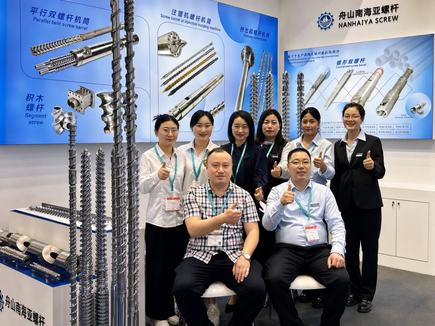
Related Articles
More insights on screw barrel technology and plastics processing.
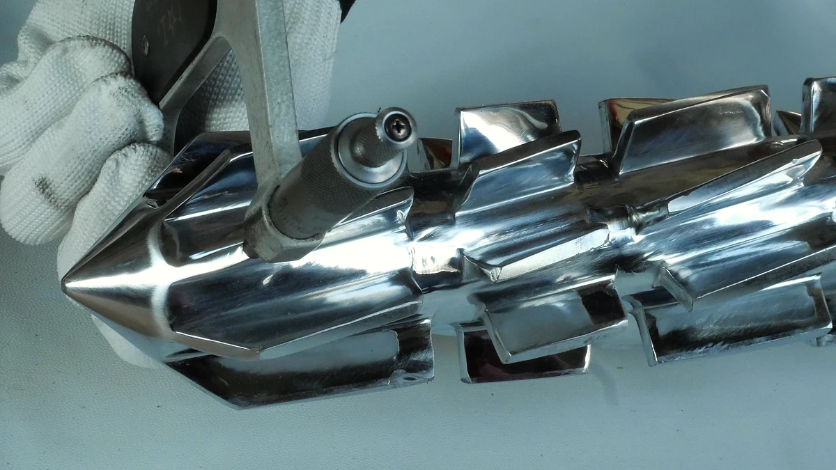
Purging Compound Decoded: Barrel Chemistry To Bottom-Line Savings
Nov 5, 2026
Learn how purging compounds clean barrels, screws, and hot runners. Compare chemical vs mechanical types, step-by-step procedures, selection tips, and cost savings.
Read Article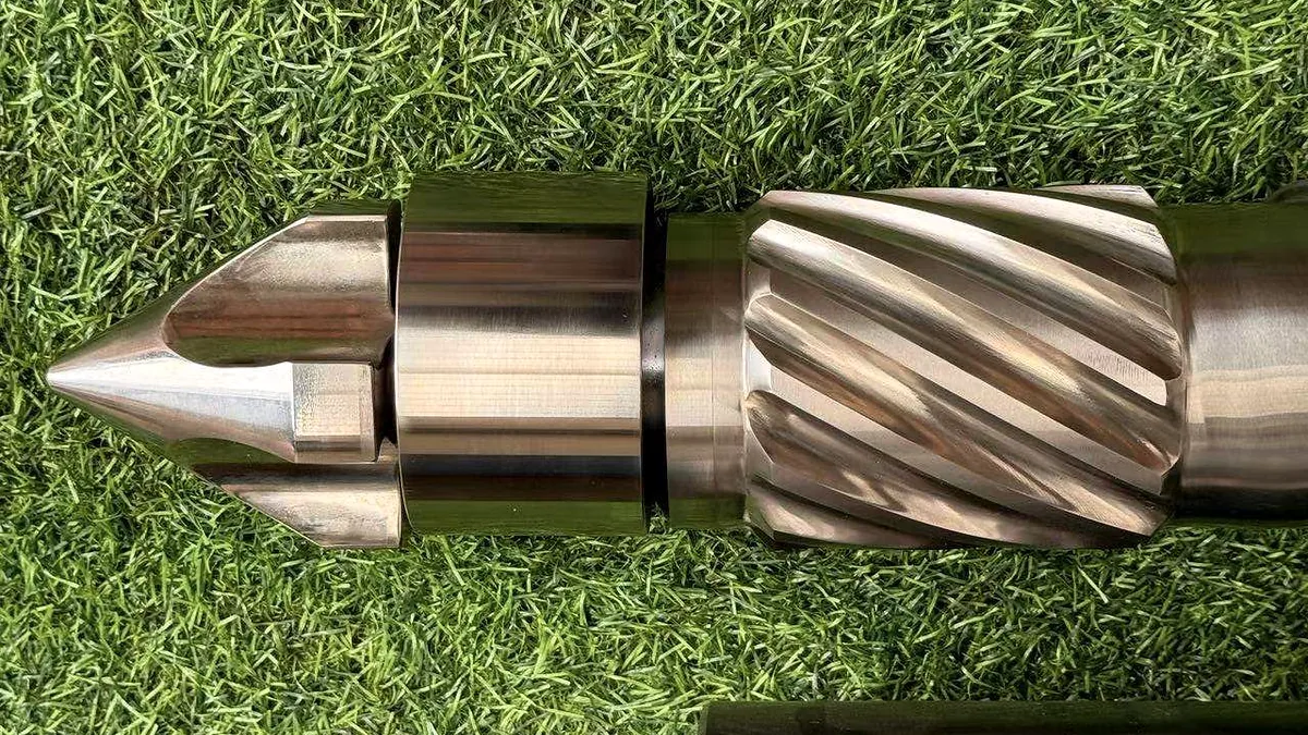
Stop Wasting Resin: How Mechanical Purging Compound Actually Works
Nov 5, 2026
Learn how mechanical purging compounds use shear force, high viscosity, and abrasive fillers to clean barrels. Covers dosage, procedures, resin matching, and maintenance tips.
Read Article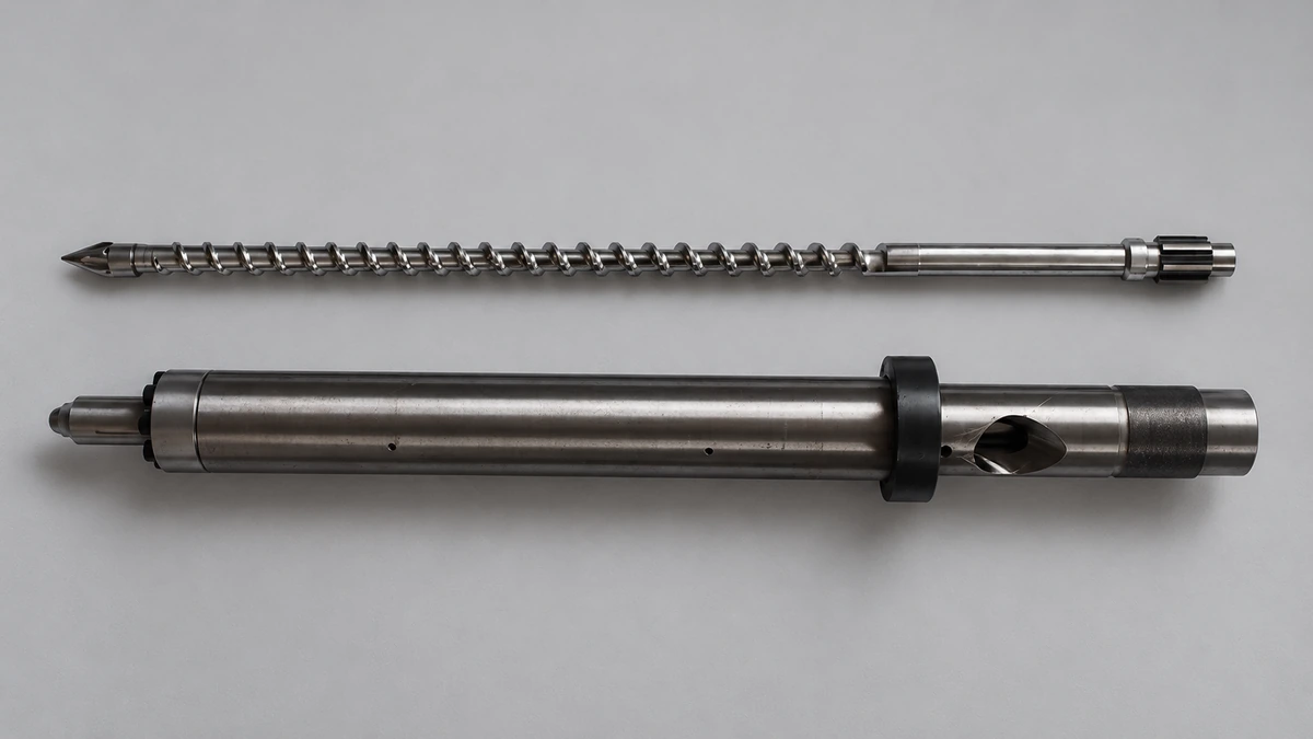
Why Your Injection Molding Back Pressure Is Costing You Parts
Nov 5, 2026
Learn how injection molding back pressure affects melt quality, cycle time, and part defects. Get resin-specific settings, troubleshooting tables, and a scientific optimization procedure.
Read ArticleLooking for something else?
Search by material, symptom or product and jump straight to the relevant page.
These are navigation suggestions based on keyword matching — not a quotation, not a delivery commitment, and not a substitute for engineering review. Final specification is confirmed by our engineers against your drawings and processed material.
Need help with screw barrel selection?
Share your machine model, processed material and application. Our team can help with pricing and technical support.