

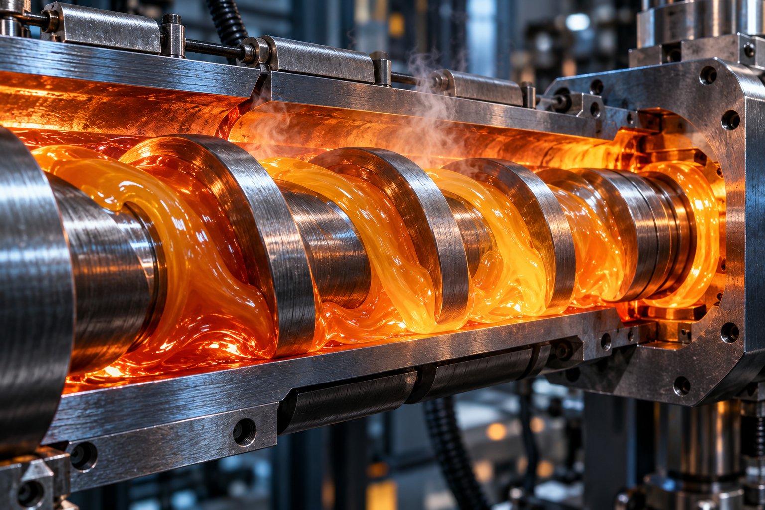
What Thermal Degradation Really Means for Injection Molders
Imagine pulling a freshly molded part off the press only to find yellow streaks, an acrid smell, or a snap-test failure that was not there yesterday. The resin has not changed. The mold has not changed. Yet something quietly destroyed the polymer before it ever reached the cavity. That something is thermal degradation in injection molding - and it is one of the most costly, misunderstood problems on the production floor.
Defining Thermal Degradation in the Molding Context
Thermal degradation in injection molding is the irreversible chemical breakdown of polymer chains caused by excessive heat, prolonged barrel residence time, or mechanical shear during the plasticizing and injection process. Once these covalent backbone bonds are broken, the molecular weight of the resin drops permanently, and no downstream adjustment can restore the original material properties.
That definition deserves a closer look, because every word carries weight. "Irreversible" means you cannot fix a degraded melt by lowering the barrel temperature mid-run - the damage is already locked into the part. "Chemical breakdown" separates this problem from simple overheating; you are not just softening the plastic, you are destroying its molecular architecture. And the three drivers - heat, time, and shear - rarely act alone. They compound each other in ways that make root-cause analysis tricky unless you understand how they interact.
As Beaumont Technologies highlights, a processor's number one responsibility is to preserve the molecular weight of the polymer during molding. When covalent bonds along the backbone of a molecular chain are broken, chain lengths shorten, molecular weight falls, and performance properties decay. This thermal decomposition can happen during material preparation, plastication, and even during first-stage injection as frictional heating pushes the melt beyond safe limits.
Why Molders Cannot Afford to Ignore It
Polymer degradation and stability might sound like topics reserved for a chemistry lab, but the consequences show up in very practical, very expensive ways:
- Brittleness and reduced impact strength - Parts that passed drop tests last month suddenly crack in the field because molecular weight has silently declined.
- Discoloration and yellowing - Even mild thermo-oxidative breakdown shifts color from subtle yellowing to dark brown or black streaks, depending on severity. Industry sources note that colors usually darken when degradation occurs and may range from yellow through orange to black.
- Splay and silver streaks - Volatile gases released during thermal decomposition leave signature surface defects that no amount of pack-pressure tuning will eliminate.
- Reduced weld-line strength - Shortened polymer chains cannot entangle as effectively across knit lines, creating hidden weak points that only appear during quality testing or, worse, in service.
- Off-gassing and odor - Acrid or chemical smells at the press are a clear signal that bond-breaking reactions are underway.
- Climbing scrap rates and customer complaints - All of the above converge into rejected parts, production downtime, and eroded margins.
The challenge is that most available resources treat this issue as either a pure polymer chemistry topic - heavy on theory, light on corrective actions - or a shallow troubleshooting checklist that tells you to "lower the melt temperature" without explaining why or when that advice falls short. A thermoset plastic loses its shape when heated because its cross-linked network breaks down differently, but for thermoplastics in injection molding, degradation is far more nuanced. Heat, residence time, moisture, shear, and even oxygen exposure each trigger distinct molecular-level mechanisms that demand distinct corrective responses.
This article bridges that gap. From the molecular reactions inside your barrel to the diagnostic steps you can post at every press, the sections ahead connect what is happening to the polymer chains with what you can actually do about it on the shop floor. Whether you are a processing engineer adjusting parameters, a setup technician chasing burn marks, or a maintenance team tracking screw wear, the framework starts at the molecule and ends at the corrective action.
And that framework begins with understanding exactly how polymer chains break apart - because the type of breakdown dictates which knob to turn first.
How Polymers Break Down at the Molecular Level
Every polymer pellet that drops into your barrel is built from thousands of repeating molecular units linked end to end into long chains. The length of those chains - measured as molecular weight - is what gives your parts their strength, toughness, and chemical resistance. Thermal degradation attacks precisely that architecture. But it does not attack it in just one way. Three distinct molecular-level mechanisms drive the breakdown, and each one leaves a different fingerprint on your molded parts.
Understanding these mechanisms is not academic trivia. When you can connect a defect on the press to a specific type of chain damage, you stop guessing and start fixing. Here is how each mechanism works in plain, shop-floor terms.
Chain Scission and Why Melt Flow Increases
Chain scission is exactly what it sounds like: a polymer chain snaps into two shorter pieces. Think of it like cutting a long rope at some point along its length. Each cut produces two shorter ropes, and neither one is as strong as the original. In polymer science, this scission process breaks the covalent bonds along the backbone, permanently reducing the average molecular weight of the melt.
There are two flavors of chain scission that matter in injection molding:
- Random chain scission - Breaks can occur at any point along the chain. Because a single random cut in a very long chain creates two substantially shorter fragments, each break has a large impact on average molecular weight. Research in polymer durability confirms that random chain scissions predominate during long-term thermal and oxidative aging in the majority of polymer systems.
- End-chain scission (unzipping) - The chain peels apart from one end, releasing one monomer unit at a time, much like pulling a zipper. Each individual break removes only a tiny fraction of the chain's total length, so the per-break impact on average molecular weight is smaller. However, the cumulative effect - and the volatile gases those freed monomers produce - can be severe.
Why does this matter at the press? When random scission chops long chains into shorter ones, the melt viscosity drops. You will notice the material flowing more easily than it should - filling faster, flashing where it never flashed before, and producing parts that feel brittle or fail impact tests. As M. Holland's technical team explains, a polymer with high average molecular weight and low melt flow rate typically showcases improved strength, toughness, and dimensional stability. Flip that relationship, and you see the problem: chain scission drives molecular weight down and melt flow rate up, stripping away exactly the properties your parts need.
Sounds complex? Picture it this way. Imagine your resin's molecular chains as a bowl of long spaghetti noodles - tangled, interlocked, and hard to pull apart. That entanglement is what gives the plastic its toughness. Chain scission chops those noodles into short pieces that slide past each other easily. The melt flows like water, but the finished part has the structural integrity of overcooked pasta.
Cross-Linking, Gels, and Black Specks
Cross-linking is chain scission's opposite. Instead of chains breaking apart, free radicals generated by heat cause neighboring chains to bond together, forming a three-dimensional network. In small, controlled amounts, cross-linking can be useful - it is the basis of vulcanized rubber and thermoset curing. Inside an injection molding barrel, though, uncontrolled cross-linking is trouble.
When chains link together, the affected material becomes increasingly resistant to flow. Localized cross-linked regions form insoluble gels - tiny lumps that refuse to melt or dissolve into the surrounding polymer stream. As these gels circulate through the barrel and hot runner, they pick up additional heat exposure, darken, and eventually carbonize into the black specks that contaminate your parts.
Which resins are most vulnerable? Polyethylene (PE), polybutadiene, and certain elastomers are especially prone to cross-linking under excessive thermal exposure. Unsaturated polymers - those with double bonds in their backbone or side groups - provide reactive sites where chains can bridge together. If you are running PE and notice a progressive increase in melt viscosity, gel particles in purge shots, or random black specks in finished parts, cross-linking is a prime suspect.
The tricky part is that cross-linking and chain scission can happen simultaneously in the same barrel. Some zones may be hot enough to trigger scission while stagnant pockets promote cross-linking. That dual behavior makes degradation symptoms confusing unless you know both mechanisms are in play.
Depolymerization and Volatile Generation
Depolymerization - sometimes called "unzipping" - is the most dramatic of the three mechanisms. The polymer chain literally reverses its own formation, peeling back from a chain end and regenerating monomer molecules one unit at a time. Those freed monomers are small, volatile, and they vaporize instantly at melt temperatures, creating gas pressure inside the melt stream.
POM (polyoxymethylene, or acetal) is the textbook example. Its backbone is built entirely from repeating -CH2O- units, and when the chain begins to unzip, it releases formaldehyde gas. This thermal decomposition accelerates sharply above approximately 220 degrees Celsius for POM homopolymer and around 240 degrees Celsius for copolymer grades. The released formaldehyde not only creates splay marks, bubbles, and gas burns on molded parts but also poses serious workplace health hazards - formaldehyde is classified as a Group 1 carcinogen by IARC.
PMMA (polymethyl methacrylate, or acrylic) follows a similar unzipping pattern, regenerating methyl methacrylate monomer under excessive heat. Polymer science literature identifies PMMA among the linear polymers containing weak monomer-monomer bonds that make end-chain scission and depolymerization especially favorable at elevated temperatures.
On the production floor, depolymerization announces itself through gas-related defects: silver streaks (splay), surface bubbles, voids within the wall section, and sometimes an audible hiss at the nozzle during purging. If you are molding POM or PMMA and see these symptoms, the polymer is literally evaporating back into its building blocks inside your barrel.
Quick-Reference: Mechanism, Defect, and Susceptible Resins
The table below maps each degradation mechanism to the defects it produces and the resin families most commonly affected. Use it as a diagnostic starting point when symptoms appear at the press.
| Mechanism | Observable Defect | Most Susceptible Resins |
|---|---|---|
| Random Chain Scission | Increased melt flow, brittleness, reduced weld-line and impact strength, discoloration | PA (nylon), PC, PET, PBT, ABS (verify specific susceptibility via resin supplier TDS) |
| Cross-Linking | Rising melt viscosity, gel particles, black specks, surface contamination | PE, polybutadiene, certain elastomers and rubbers (verify via resin supplier TDS) |
| Depolymerization (Unzipping) | Splay / silver streaks, bubbles, voids, off-gassing odor, gas burns | POM (acetal), PMMA (acrylic), PTFE (verify via resin supplier TDS) |
Note: Resin-specific degradation behavior varies by grade, stabilizer package, and processing conditions. Always confirm susceptibility data against the technical data sheet provided by your resin supplier.
These three mechanisms - scission, cross-linking, and depolymerization - rarely operate in isolation. Real-world thermal degradation of polymers during injection molding often involves combinations of all three, driven by different conditions in different zones of the barrel. A single production run can exhibit chain scission in the melt mainstream while cross-linking builds in a dead spot behind a worn check ring, and depolymerization releases gas at an overheated hot-runner drop. That overlap is exactly why isolating the degradation type matters just as much as recognizing that degradation is occurring at all - a distinction the next section makes even sharper by mapping the five specific degradation categories every molder should be able to tell apart.

Five Degradation Types Every Molder Should Distinguish
Chain scission, cross-linking, and depolymerization describe how polymer chains break apart. But on the shop floor, a more practical question comes first: what triggered the breakdown? Five distinct degradation types can cause material to degrade during - or around - the injection molding process, and each one has a different primary driver, shows up in a different place, and demands a different fix. Lumping them all under the single label "thermal degradation" leads to the wrong corrective action more often than you might expect.
Here is how to tell them apart.
Thermal and Thermo-Oxidative Degradation
Pure thermal degradation is driven by heat alone. Picture the barrel core during plastication: resin surrounded by hot steel, no air contact, just accumulated energy breaking bonds. When barrel temperatures climb above the polymer's safe processing window - or when a thermal polymer sits too long in an overheated zone - chain scission and depolymerization accelerate without any help from oxygen.
Thermo-oxidative degradation adds a second ingredient: oxygen. Where does oxygen enter an injection molding barrel? Primarily through the feed throat, during color or material changes when the screw runs partially empty, and through any gaps in hopper seals. Oxygen reacts with free radicals generated by heat, launching an autoxidation cycle. Research on PLA degradation has confirmed that thermo-oxidative reactions produce peroxide radicals that abstract hydrogen from neighboring chains, propagating damage far beyond the initial break point. The resulting defects include yellowing, surface haze, and embrittlement - even at barrel temperatures that fall within the resin supplier's recommended range.
Practical countermeasure? Purge residual air from the barrel before starting production. Keep the hopper sealed and feed throat blanketed when processing oxidation-sensitive resins. And remember: thermo-oxidative breakdown can start at lower temperatures than pure thermal degradation because oxygen lowers the activation energy required to initiate radical formation.
Hydrolytic Degradation in Hygroscopic Resins
This is the type that catches processors off guard most frequently. Hydrolytic degradation does not need excessive barrel temperatures to cause catastrophic molecular-weight loss. It only needs moisture.
When hygroscopic resins like nylon (PA6, PA66), polycarbonate (PC), PET, or PBT absorb water, that moisture travels into the barrel with the pellets. At melt temperature, water molecules attack the ester or amide bonds in the polymer backbone, splitting chains in a reaction that is irreversible once it occurs. The result is a sharp drop in viscosity, reduced strength, and surface defects like splay and bubbles - all while your barrel temperature set-points look perfectly normal.
What makes hydrolytic degradation especially treacherous is how little moisture it takes. Many engineering resins require moisture levels below 0.02-0.04% before processing. Exceed that threshold, and degradation begins the moment resin reaches melt temperature. Regrind multiplies the risk because ground particles have far more surface area than virgin pellets, absorbing moisture faster during storage and transfer. Reprocessing regrind without re-drying is one of the fastest paths to polymer degradation and stability problems on the floor.
The primary defense is straightforward: proper pre-drying at the temperature, time, and dew point specified by the resin supplier - verified with measurement, not assumed by the clock.
Mechanical Shear Degradation
Even with barrel heaters set conservatively, the actual melt temperature can soar well above the set-point. The culprit? Viscous shear heating - the frictional energy generated as the screw rotates and pushes high-viscosity melt through restrictive flow paths.
Higher screw speed increases the shear rate, which increases frictional heat. Higher back pressure extends recovery time and forces the melt through tighter clearances. Together, these two parameters can push the real melt temperature 10-30 degrees Celsius above what the controller displays. Thin-wall applications and high-speed cycles are especially vulnerable because they require fast injection velocities and elevated screw RPMs, both of which amplify shear-driven heat buildup.
The defects mirror those of pure thermal breakdown - discoloration, brittleness, splay - but the root cause is mechanical energy, not heater bands. That distinction matters because lowering barrel set-points will not solve the problem if shear heating is the true driver. Instead, you need to optimize screw speed, reduce back pressure, or address flow-path restrictions in the runner and gate system.
Photo and UV Degradation
Photo degradation is the one type on this list that is not primarily a barrel or mold issue. Ultraviolet radiation breaks polymer bonds through a photon-energy mechanism, generating free radicals that initiate chain scission and surface embrittlement over time.
So why include it here? Two reasons. First, regrind stored in open bins under warehouse lighting or near windows absorbs UV energy that weakens the material before it ever reaches the press. Second, parts destined for outdoor use or UV-exposed environments need stabilizer packages designed during compounding - and those stabilizers deplete faster when the base polymer has already been partially degraded by other mechanisms during molding. Recognizing photo degradation as part of the broader polymer degradation stability picture helps molders manage regrind quality and set realistic expectations for part service life.
All Five Types at a Glance
The table below puts the full framework in one place. When a defect appears, start by identifying which degradation type best matches the conditions, then follow the corresponding countermeasure.
| Type | Primary Driver | Where It Occurs | Key Resins Affected | Primary Countermeasure |
|---|---|---|---|---|
| Thermal | Excessive heat (no oxygen required) | Barrel core, hot-runner drops, nozzle tip | POM, PVC, PMMA, and any resin held above its safe melt-temperature ceiling | Reduce barrel/hot-runner temperatures; minimize residence time |
| Thermo-Oxidative | Heat + oxygen exposure | Feed throat, partially filled barrel, color-change purges | PE, PP, ABS, PA, PLA (verify via supplier TDS) | Purge air from barrel; seal hopper; use nitrogen blanket for sensitive resins |
| Hydrolytic | Moisture reacting at melt temperature | Barrel (moisture enters with undried pellets) | PA6, PA66, PC, PET, PBT, PEI, PSU | Pre-dry to supplier spec; verify with moisture analyzer; re-dry regrind |
| Mechanical (Shear) | Viscous frictional heating from screw speed, back pressure, and flow restrictions | Screw metering zone, check-ring area, gates, thin-wall sections | High-viscosity resins: PC, PMMA, rigid PVC, filled engineering grades | Optimize screw RPM and back pressure; widen restrictive flow paths; confirm actual melt temp with air shot |
| Photo / UV | Ultraviolet radiation energy | Regrind storage, outdoor part service life | PP, PE, ABS, PA (without UV stabilizers) | Store regrind in opaque containers; specify UV-stabilizer packages for outdoor-use parts |
Note: Resin susceptibility varies by grade and stabilizer package. Always cross-reference with your resin supplier's technical data sheet before finalizing process changes.
Distinguishing these five types transforms troubleshooting from guesswork into structured diagnosis. Yet even a correct diagnosis is only half the equation - the other half is knowing exactly which processing parameter is feeding the degradation mechanism you have identified. Barrel temperature profiles, residence time ratios, screw speed, and back pressure each interact with these five types in specific, predictable ways that point straight to corrective action.
Processing Parameters That Drive Polymer Thermal Degradation Risk
Knowing which degradation type is at work only gets you halfway to a fix. The other half is pinpointing which machine setting is feeding it. Every parameter you dial into the controller - barrel temperatures, cycle times, screw RPM, back pressure - interacts with the resin in ways that either keep polymer chains intact or quietly tear them apart. The challenge is that these parameters rarely act alone. They stack on top of each other, and the combined effect on the actual melt temperature can be dramatically different from what the display suggests.
Here is where the structured cause-and-effect mapping begins.
Barrel Temperature Profile and Hot-Runner Zones
Your barrel heater set-points influence the melt, but they do not equal the melt temperature. As Orbital Plastics Consulting emphasizes, barrel thermocouples measure the steel temperature of the barrel wall - not the actual polymer temperature inside. Two machines with identical zone settings can produce melts that differ by 20-40 degrees Fahrenheit due to differences in shear, screw geometry, and residence time. That gap between displayed and true melt behavior is where most thermolytic breakdown originates.
Setting the rear zone too high is a common and underappreciated mistake. An excessively hot rear zone softens pellets too early, reducing the solid-bed friction the screw needs to convey material forward efficiently. The result? Material lingers longer in the barrel, compounding residence-time degradation. On the other end of the barrel, an overly aggressive front zone or a hot-runner drop running hotter than the rest of the profile creates localized overheating. Even a few degrees of imbalance across hot-runner zones can push one cavity's melt past its thermal ceiling while the others remain fine - producing intermittent burn marks or discoloration that seem random until you check individual zone temperatures.
The takeaway for any high temp polymer application is simple but often skipped: measure your actual melt temperature. Perform an air shot on cycle, catch the purge, and read it with a pyrometer. Compare that number to the resin supplier's recommended melt-temperature range. If the measured value exceeds the set-point by a significant margin, shear heating or an incorrect barrel profile is the likely culprit - not the heaters themselves.
Residence Time, Cycle Time, and Shot-to-Barrel Ratio
Residence time is the total duration resin spends inside the heated barrel, exposed to both conductive heat from the heater bands and frictional heat from screw rotation. The longer it stays, the more energy accumulates in the polymer chains - and the closer those chains creep toward irreversible breakdown.
What controls residence time? Primarily the relationship between your shot size and the barrel's total capacity. Rosti's engineering team notes that small shot sizes using minimal barrel capacity result in long residence times and polymer degradation, while shots exceeding roughly 50% of barrel capacity can lead to poor melt uniformity and extended screw recovery. A widely cited guideline recommends keeping the shot between 25% and 65% of rated barrel capacity, with an additional cushion for safety. When you fall below that lower threshold - say, running a small part on an oversized press - each pellet takes multiple cycles to travel from feed throat to nozzle, soaking up heat the entire way.
Production interruptions make the problem worse. Lunch breaks, mold stoppages for quality checks, and robot faults all leave material sitting motionless in a hot barrel. Even a five-minute unplanned pause can push residence time well beyond what the resin can tolerate, especially for thermally sensitive polymers like POM or PVC. If your production schedule involves frequent stops, consider implementing an automatic purge cycle or reducing barrel temperatures during extended idle periods to limit thermal polymerization and chain-breaking reactions.
Screw Speed and Back Pressure Interactions
Screw RPM and back pressure are two sides of the same coin - and together, they can push actual melt temperature far beyond the controller's set-point. Here is how.
When screw speed increases, the shear rate inside the screw channels rises proportionally. That shear generates frictional heat - a phenomenon called viscous dissipation or drag flow heating. Engineering analysis from MD Plastics confirms that screw shear, not heater bands, is the main source of heat generation during plastication. Higher RPM means more rotational energy converted to heat inside the polymer itself, particularly in the compression and metering zones where channel depths are shallow and shear rates peak.
Back pressure adds another layer. It resists the screw's rearward travel during recovery, forcing the melt through tighter effective clearances and extending the time the screw spends rotating. More rotation time at elevated shear equals more frictional heat generated per cycle. Crank both parameters up simultaneously - high RPM to shorten recovery and high back pressure to improve mixing - and you can easily overshoot the resin's safe melt-temperature window by 10-30 degrees Celsius without a single heater zone reading out of range.
The defects that follow - discoloration, splay, brittleness, and reduced weld-line strength - look identical to those caused by excessive barrel temperature. That similarity is precisely why measuring actual melt temperature with an air shot is so critical. Without that measurement, you might chase heater settings endlessly while the real driver is mechanical energy input from screw speed and back pressure working in tandem.
Diagnostic Reference: Parameter to Defect to Corrective Action
The table below maps each key processing parameter to the degradation mechanism it triggers, the defect you will see on the part or in the melt, and the corrective action to take first. Print it, post it at the press, and use it as your starting checklist whenever polymer thermal degradation symptoms appear.
| Parameter | Degradation Mechanism | Observable Defect | Corrective Action |
|---|---|---|---|
| Rear-zone temperature too high | Early softening extends effective residence time; thermo-oxidative exposure near feed throat | Yellowing, discoloration, increased melt flow, brittleness | Reduce rear-zone set-point; verify feed-throat cooling is adequate; measure actual melt temperature |
| Front-zone or nozzle temperature too high | Localized thermal and thermolytic chain scission at the melt front | Burn marks at gate, dark streaks, splay, drool or stringing | Lower front-zone and nozzle set-points 5-10 degrees; check hot-runner zone balance; perform air-shot melt-temp check |
| Hot-runner zone imbalance | Localized overheating at specific drops or manifold sections | Intermittent burn marks or color shift in select cavities only | Audit individual hot-runner zone temperatures; balance drops to within the resin's recommended range |
| Oversized barrel (low shot-to-barrel ratio) | Extended residence time exposes melt to cumulative heat | Generalized yellowing, off-gassing odor, viscosity drop, brittleness | Move mold to a smaller-barrel press; if not possible, reduce cycle time or lower barrel temps to compensate |
| Production interruptions (idle barrel) | Stagnant melt degrades via thermal and thermo-oxidative mechanisms | Dark streaks or black specks on first shots after restart, acrid odor | Implement auto-purge on idle timer; reduce barrel temps during planned stops; purge before restarting production |
| Excessive screw RPM | Viscous shear heating raises actual melt temp above set-point | Splay, discoloration, reduced impact and weld-line strength | Reduce screw speed; verify actual melt temp with air shot; accept slightly longer recovery if needed |
| Excessive back pressure | Extended recovery time + increased shear compound heat input | Same as above - splay, yellowing, melt-viscosity drop, brittleness | Lower back pressure to minimum needed for consistent cushion and melt homogeneity; recheck melt temp |
| High RPM + high back pressure combined | Synergistic shear heating can push melt 10-30 degrees C above set-point | Severe discoloration, gas burns, splay, part embrittlement, volatile odor | Reduce both parameters incrementally; measure actual melt temp after each adjustment; optimize for lowest shear that still delivers a homogeneous melt |
Tip: If corrective actions targeting barrel temperature do not resolve the defect, the root cause is likely mechanical - either shear-driven heat or hardware-related. That distinction points directly to the plasticizing hardware itself: the screw, barrel, and check ring whose geometry and condition shape every gram of melt that reaches your cavity.
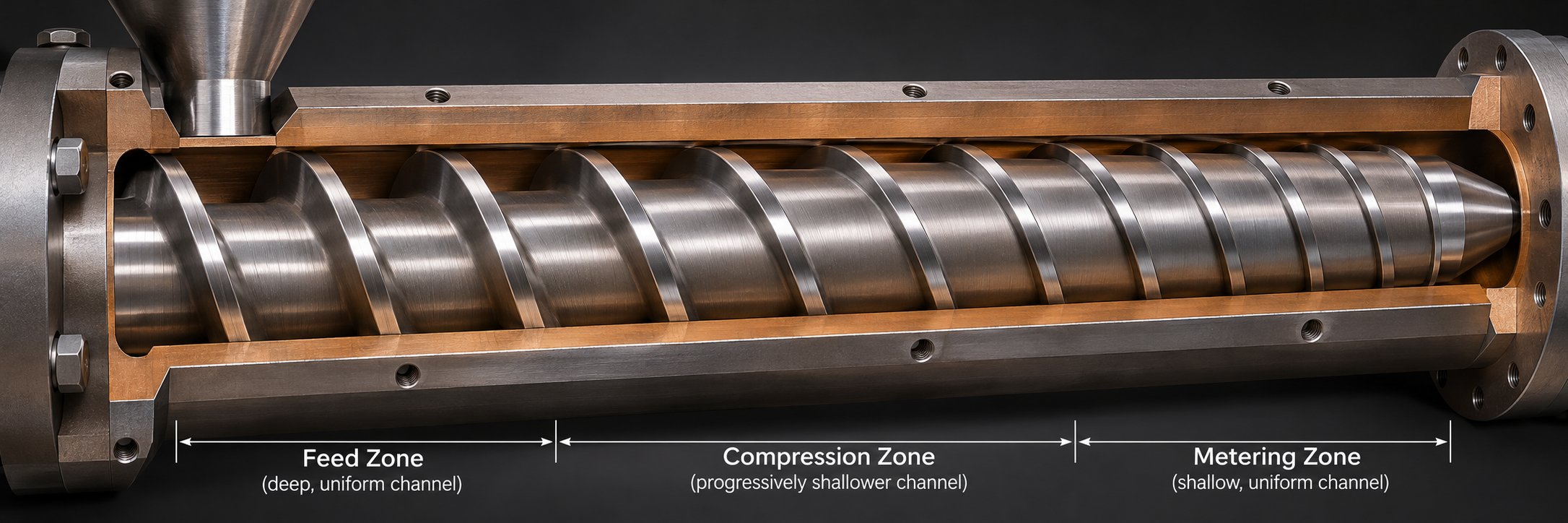
How Screw Design and Wear Compound Thermal Degradation
Your barrel profile is dialed in. Screw RPM and back pressure are within range. Yet the degraded polymer keeps showing up - streaks, specks, brittleness that defies every parameter tweak you have tried. When corrective actions targeting temperature and time fail to resolve chronic degradation, the problem is often not what you are setting on the controller but what is physically happening inside the plasticizing hardware. The screw, barrel bore, and check ring are the last components most molders suspect, yet their geometry and condition shape every degree of actual melt temperature, every second of residence time, and every defect that reaches the cavity.
This is the variable nearly every troubleshooting guide overlooks. Understanding how screw design and wear interact with thermal degradation in injection molding can turn a chronic, frustrating defect pattern into a clear-cut corrective action.
Compression Ratio and Its Impact on Shear Heating
The compression ratio of an injection screw is the ratio of the feed-zone channel depth to the metering-zone channel depth. It determines how aggressively the screw compacts and shears the resin as it travels from hopper to nozzle. A screw with a higher compression ratio squeezes the melt through a progressively tighter channel, generating more frictional heat and delivering a more uniform melt - up to a point. Push that ratio too high for a given resin, and you cross the line from efficient melting into destructive shear heating.
As Essentra Components explains, the higher the compression ratio, the greater the shear heat imparted to the resin, the greater the heat uniformity of the melt, and the greater the potential for creating stresses in some plastic resins. That last point is critical. Excessive shear does not just raise the temperature - it mechanically tears polymer chains apart through the same viscous dissipation mechanism discussed in the previous section. The true melt temperature climbs above the barrel set-point, and the degradative reactions that follow look identical to a simple overheating problem. Without pulling the screw and evaluating its geometry, you could spend weeks chasing phantom temperature issues.
The opposite extreme creates problems too. A compression ratio that is too low for the resin leaves pellets partially unmelted, producing an inconsistent melt with cold spots and hot spots side by side. Those unmelted particles force surrounding material to absorb extra shear and heat to compensate, creating localized degradation pockets even though the average melt temperature looks acceptable. You will notice this as random splay, inconsistent color, or occasional brittle parts mixed in with good ones - a maddening quality pattern that no single parameter adjustment can fix.
Typical general-purpose screws use compression ratios around 2.0:1 to 2.5:1, which works adequately for commodity resins like ABS, PP, and PE. Screw design references show that heat-sensitive resins like PVC and POM benefit from low-compression separation-type screws (around 1.6:1), while filled engineering grades and barrier screws may run 2.8:1 to 3.0:1 for adequate melting energy. Using the wrong ratio for your resin is not a minor mismatch - it is a root cause for critical components failure in generic plastic molding setups where one screw is expected to handle every material.
Worn Screws, Check Rings, and Material Hang-Up
Even a perfectly specified screw degrades over time - not the polymer kind, but the mechanical kind. Flight lands wear against the barrel wall, check rings lose their sealing surfaces, and the once-precise geometry that controlled melt behavior gradually loosens into a sloppy fit. The consequences for polymer quality are severe and often overlooked until defect rates spike.
When flight-land clearance increases due to wear, resin leaks backward over the flights during recovery. That leaked material does not simply rejoin the forward melt stream on the next cycle. It recirculates, accumulating additional heat exposure with each pass. The effective residence time for those trapped molecules stretches far beyond what you would calculate from shot size and cycle time alone. Industry observations confirm that when a screw has worn flights or the check ring seals inconsistently, carbonized material eventually breaks loose and enters the melt stream, producing the black specks that contaminate finished parts. Once a carbon layer forms in these regions, ordinary purging cannot fully remove it - a screw pull becomes the only reliable remedy.
Worn or damaged check rings create an even more insidious problem: dead spots. These are small pockets where material stagnates because the check ring no longer seats cleanly. Resin trapped in these dead zones bakes at barrel temperature cycle after cycle, slowly carbonizing into hard, dark particles. When they finally break free - often randomly - they appear as black specks or char flakes on part surfaces. The randomness of these defects makes them especially difficult to diagnose, because they do not correlate cleanly with any process change you have made.
Worn components also rob you of shot-to-shot consistency. When the check ring does not seal reliably, cushion size varies, recovery time fluctuates, and the effective shear and residence time change from one cycle to the next. Degradation becomes unpredictable - some shots come out clean while others show splay or discoloration under identical settings. If your process data shows widening variation in cushion position or recovery time, screw and check-ring wear should be at the top of your investigation list.
Matching Screw Geometry to Resin and Application
Here is a question worth asking at your next mold setup: is the screw in this machine actually designed for the resin you are running? In many shops, the honest answer is no. General-purpose screws ship with the machine, and they stay in service across every material changeover for years - sometimes decades. That approach is a compromise at best and a degradation driver at worst.
Heat-sensitive resins demand screws engineered to minimize shear and residence-time exposure. PVC, for example, has one of the narrowest safe processing windows of any thermoplastic. A high-compression general-purpose screw generates enough frictional heat to push PVC past its decomposition threshold, releasing corrosive HCl gas that damages the barrel bore, contaminates the melt, and creates a cascading failure pattern. POM (acetal) is similarly unforgiving - its tendency to depolymerize means that any screw geometry creating stagnant zones or excessive shear will produce formaldehyde gas and splay defects. Both resins benefit from low-compression, low-shear screw designs with shallow, consistent channel depths that move material through the barrel quickly and gently.
On the other end of the spectrum, semi-crystalline engineering resins like PA (nylon) and PET need substantial melting energy delivered efficiently. An undersized compression ratio or a worn screw that cannot generate adequate shear leaves crystalline structures partially intact, producing an inconsistent melt that fills poorly and yields weak parts. Barrier screws with higher compression ratios and dedicated mixing sections deliver the energy these resins need without the residence-time penalty of simply cranking up barrel temperatures.
Replacing a worn or mismatched screw is often the single highest-impact corrective action for chronic degradation problems. It is also the action most commonly delayed because it feels like a capital expense rather than a process fix. In reality, the cost of a correctly specified screw and barrel set is a fraction of the cumulative scrap, downtime, and customer complaints generated by plasticizing hardware that does not match the application. Suppliers like NANHAIYA engineer custom injection molding screw barrels around specific machine platforms, resin characteristics, and shot requirements - an approach that eliminates the compromise inherent in general-purpose designs. Their technical review evaluates screw geometry, existing wear patterns, melting efficiency, mixing needs, and material-retention concerns to recommend a configuration matched to the actual processing demands, which is especially valuable for molders dealing with recurring degradation tied to plasticizing hardware.
Whether you source from a specialist or work with your machine OEM, the principle is the same: the screw is not a universal commodity part. It is a precision tool that must match the resin, the shot, and the application - and when it does not, every other parameter adjustment you make is fighting a battle it cannot win.
Correctly specified and well-maintained plasticizing hardware eliminates a major category of degradation causes. But even with the right screw in prime condition, defects can still appear - and when they do, the ability to read each symptom, trace it to a specific root cause, and follow a structured diagnostic sequence is what separates a quick fix from a week of trial and error.
Recognizing Degradation Symptoms and Tracing Root Causes
A defect just landed on the inspection table. Is it a burn mark, splay, or early-stage discoloration? Each symptom points to a different mechanism, a different severity level, and a different first corrective step. Misreading the symptom sends you chasing the wrong variable - and that costs hours, material, and credibility with your customer. The key to fast, accurate burn marks injection molding troubleshooting is learning to read what the part is telling you before touching a single controller setting.
Burn Marks, Splay, and Discoloration
These three surface defects look superficially similar - all involve streaking or color changes - but their origins are fundamentally different.
Burn marks are dark brown to black deposits of carbonized material, typically concentrated at the last areas to fill, near vent locations, or at flow-path dead ends. They form when trapped air compresses during injection and ignites the polymer surface - the so-called diesel effect - or when already-carbonized material breaks loose from stagnant zones inside the barrel or hot runner. Injection molding defect analysis confirms that burn marks are usually found near sharp corners, flow-path ends, or areas where air cannot escape the mold cavity, with contributing factors including high injection speeds, insufficient venting, and improper gate design.
Splay, or silver streaks, is a gas-driven surface defect that fans outward from the gate in the flow direction. The streaks appear silvery-white and feel smooth to the touch. What causes splay silver streaks? Three sources, each with a distinct visual signature. Detailed splay pattern analysis shows that U-shaped, cloudy streaks typically indicate moisture flashing to steam in the barrel, shiny streaks suggest thermal degradation volatiles, and a random spray pattern points to entrained air from excessive screw decompression or a leaking nozzle seat. Identifying which pattern you are seeing is the entire diagnostic job, because the fixes for moisture, heat, and air are completely different.
Discoloration or yellowing without accompanying burn marks or streaks is the subtlest and most dangerous symptom. It signals mild thermo-oxidative breakdown - the polymer chains are shortening, but not yet enough to produce dramatic surface defects. Think of it as an early warning light. If you catch yellowing early and investigate, you prevent the full cascade of injection molding discoloration defects, brittleness, and scrap that follows when the degradation progresses unchecked.
Brittleness, Reduced Weld-Line Strength, and Odor
Not all degradation announces itself visually. Some of the most consequential damage hides inside the part.
Brittleness and reduced impact strength indicate that significant molecular-weight loss has already occurred. Shortened chains cannot entangle effectively, so the part snaps under loads it once absorbed easily. You might not see anything wrong on the surface, but drop tests, flex tests, or field failures reveal the truth.
Weld line strength degradation is especially insidious. Where two melt fronts meet, degraded polymer chains with reduced molecular weight form weaker bonds across the knit line. Research on weld-line strength in PA6 composites found that tensile strength at weld lines ranged from 65.51 MPa to 73.19 MPa depending on processing parameters - and that melt temperature had a significant impact on that bonding quality. When the resin arriving at the weld line has already lost molecular weight to degradation, even optimized process settings cannot fully compensate. Parts pass visual inspection but fail mechanical QC, making routine tensile and impact testing critical rather than optional.
Off-gassing odor - particularly acrid, acidic, or formaldehyde-like smells - signals advanced degradation. PVC releases hydrochloric acid gas when it decomposes; POM releases formaldehyde. If operators at the press notice a sharp chemical smell, degradation is no longer subtle. It demands immediate investigation, both for part quality and for workplace safety.
A Structured Diagnostic Flowchart
When degradation symptoms appear, resist the urge to adjust the first parameter that comes to mind. Instead, follow this diagnostic sequence from most common cause to least obvious. Each step either confirms or eliminates a root cause before you move on, preventing the wasted time of changing multiple variables at once and guessing which one worked.
- Verify drying conditions. Check dryer dew point, hopper temperature, and actual residence time in the dryer - not just the set-point. Measure the material's moisture content with an analyzer. Undried hygroscopic resin is the single most frequent cause of splay and hidden strength loss.
- Measure actual melt temperature with an air shot. Purge on cycle, catch the melt, and read it with a pyrometer. Compare to the resin supplier's recommended range. If the measured value exceeds the set-point significantly, shear heating or an incorrect barrel profile is driving the problem.
- Review residence time and shot-to-barrel ratio. Calculate whether the shot size falls within the recommended percentage of barrel capacity. If the barrel is oversized for the shot, material is soaking in heat far longer than necessary.
- Inspect screw and barrel wear. Check flight-land clearance, check-ring sealing, and look for scoring or buildup. Worn components extend effective residence time and create stagnation zones where material carbonizes into black specks.
- Audit hot-runner zone temperatures. Compare individual zone readings and look for imbalances. A single overheated drop can produce intermittent defects in specific cavities while others run clean.
- Examine material handling and regrind ratios. Confirm regrind has been re-dried to the same specification as virgin material. Verify the regrind percentage stays within acceptable limits - typically below 20-25% - and inspect for contamination, fines, or dust that accelerate degradation.
Print this sequence and post it at the press. When a degradation defect appears, the operator or setup technician starts at step one and works down the list. Each step isolates a single variable, and as practical troubleshooting methodology emphasizes, changing one variable at a time and running 20-30 consecutive shots after each change is the fastest way to confirm a root cause rather than guessing.
A repeatable diagnostic process catches problems faster, but it works best when you already know how your specific resin tends to fail. Different polymer families degrade through different mechanisms, at different thresholds, and with different warning signs - which is exactly why a resin-by-resin vulnerability map belongs in every processor's reference library.
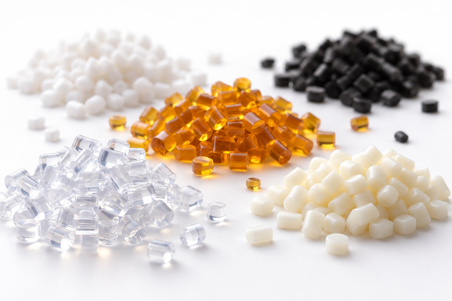
Material-Specific Degradation Vulnerabilities by Resin Family
Every resin has a personality. Some shrug off high barrel temperatures but collapse at the first hint of moisture. Others tolerate humidity just fine but unzip into toxic gas the moment they overheat. Running the same process-protection strategy across every material in your lineup is like prescribing the same medicine for every patient - it might help one and harm another. The diagnostic flowchart from the previous section tells you where to look; this section tells you what to expect based on the specific polymer sitting in your hopper.
Here is a resin-by-resin breakdown of the degradation behaviors that matter most on the molding floor.
Hygroscopic Resins and Hydrolytic Sensitivity
If there is one category of nylon moisture degradation injection molding problems that generates the most scrap industry-wide, it is hydrolysis in undried engineering resins. PA6, PA66, PC, PET, and PBT all absorb ambient moisture through their molecular structure - and at melt temperature, that absorbed water attacks the ester or amide bonds holding the polymer chains together.
What makes this so dangerous? The damage happens fast, silently, and at barrel temperatures that look perfectly normal on the controller. You do not need to overheat nylon to destroy it. You just need to skip the dryer - or trust it without verifying. As Plastics Technology reports, moisture levels upward of 0.15% in specialty nylons like PPA can cause cosmetic problems such as splay or silver streaking, while higher levels lead to hydrolysis and a significant reduction in mechanical properties. For standard PA66, most suppliers specify a maximum moisture content of 0.02% before processing - a threshold that ambient shop air can push past in under an hour of open-container exposure.
Polycarbonate is equally unforgiving. PC's carbonate linkage is vulnerable to water attack at melt temperature, producing chain scission that drops viscosity and impact strength simultaneously. PET and PBT share the same ester-bond vulnerability. Imagine spending thousands on a high-cavity PET preform mold and then losing molecular weight - and bottle performance - because the dryer's dew point drifted from -40 degrees to -20 degrees overnight. It happens more often than anyone likes to admit.
Regrind amplifies the risk. Ground particles have dramatically more surface area than virgin pellets, so they absorb moisture faster during storage and pneumatic transfer. Reprocessing regrind without re-drying to the same specification as virgin material is one of the fastest paths to hydrolytic breakdown on the floor. And each regrind generation further depletes whatever thermal stabilizer was compounded into the original resin, leaving the base polymer increasingly vulnerable even when drying is done correctly.
Shear-Sensitive and Thermally Unstable Resins
Some polymers have processing windows so narrow that a few degrees or a few extra RPM on the screw can tip them from stable to destructive. PVC, POM, and PMMA each fall into this category - but for different reasons.
PVC operates within one of the tightest thermal stability processing windows of any commercial thermoplastic. Its decomposition releases hydrochloric acid (HCl) gas, which is corrosive to barrel and screw steel, toxic to operators, and autocatalytic - meaning the released acid accelerates further degradation of the remaining polymer. Once PVC degradation starts, it feeds on itself. That is why PVC demands low-compression, low-shear screw designs, conservative barrel temperatures, and minimal residence time. Any stagnant zone in the barrel or hot runner where PVC can linger becomes a source of progressive char buildup and corrosive attack.
POM (acetal) brings a completely different hazard. Its backbone of repeating -CH2O- units makes it prone to depolymerization - the unzipping reaction that regenerates formaldehyde monomer gas. Technical analysis from Cylex Plastics confirms that POM homopolymer begins depolymerizing at temperatures above approximately 220 degrees Celsius, while POM copolymer grades offer better stability up to around 240 degrees Celsius because comonomer units block the continuous zipper-like chain reaction. For POM acetal depolymerization prevention, processors should keep melt temperatures constrained to the lower end of the operational range - typically 190 to 210 degrees Celsius for copolymers - minimize barrel residence time, and consider nitrogen purging of the hopper to eliminate oxygen exposure that accelerates oxidative chain scission. Formaldehyde is a Group 1 carcinogen classified by IARC, so workplace ventilation is not optional when molding acetal.
PMMA (acrylic) follows a similar unzipping pattern, regenerating methyl methacrylate monomer under excessive heat. Because PMMA is often chosen for optical clarity applications, even mild degradation that introduces haze, yellowing, or gas bubbles renders the part unusable. Low screw compression, gentle back pressure, and strict adherence to the supplier's melt-temperature ceiling are the primary defenses.
All three of these resins share a common requirement: specific screw geometry designed to minimize shear and move material through the barrel quickly. A general-purpose screw is a compromise these polymers cannot afford.
High-Temperature Engineering Resins
At the top of the temperature ladder sit PEEK, PEI (Ultem), PPS, and LCP - resins that process at barrel temperatures ranging from roughly 300 to 400 degrees Celsius depending on grade and fill level. These engineering resin thermal limits leave almost no margin for error. When your set-point is already near the polymer's decomposition threshold, even a modest hot-runner imbalance or a slight residence-time extension can push material over the edge.
PEEK, for instance, melts at approximately 343 degrees Celsius and can operate continuously at up to 260 degrees Celsius in service, as comparative polymer data confirms. Processing PEEK typically requires barrel temperatures between 360 and 400 degrees Celsius. At those levels, any dead spot in the barrel, any worn check-ring pocket, or any idle-time pause gives the polymer enough energy to degrade rapidly. PPS melts around 280 degrees Celsius and processes at comparably demanding temperatures, though its superior chemical resistance gives it an edge in environments involving harsh solvents.
PEI and LCP present their own challenges. PEI's amorphous structure requires high barrel temperatures for adequate flow, and it is hygroscopic - combining hydrolytic and thermal risk into a single resin. LCP's liquid-crystalline structure is highly shear-sensitive, meaning flow-path design and injection speed matter as much as temperature control.
One factor that often gets overlooked with high-temperature engineering resins is stabilizer depletion. Antioxidant additive packages compounded into these materials protect the base polymer by sacrificing themselves - scavenging free radicals before they can propagate chain scission. But each heat history cycle consumes a portion of that stabilizer. Excessive residence time burns through the antioxidant budget faster. And regrind passes stack additional heat histories on top of the original processing cycle, progressively depleting the stabilizer concentration until the base polymer is effectively unprotected. If your regrind program includes high-temperature resins, tracking regrind generation count and limiting regrind ratios is critical to maintaining material integrity.
Quick-Reference: Resin Family Degradation Guide
The table below consolidates the key vulnerabilities and prevention measures for the most commonly molded resin families. Use it alongside your resin supplier's technical data sheet to confirm grade-specific temperature limits and drying requirements.
| Resin Family | Max Recommended Melt Temp | Primary Degradation Risk | Key Prevention Measure |
|---|---|---|---|
| PA6 / PA66 (Nylon) | Verify per grade TDS (typically 260-300 °C range) | Hydrolysis from moisture; thermo-oxidative at extended residence | Dry to below 0.02% moisture; re-dry all regrind; minimize residence time |
| PC (Polycarbonate) | Verify per grade TDS (typically 280-320 °C range) | Hydrolysis from moisture; yellowing from thermo-oxidative attack | Dry to below 0.02% moisture; avoid excessive barrel temps; limit regrind passes |
| PET / PBT (Polyesters) | Verify per grade TDS (typically 260-290 °C range) | Hydrolysis at melt temperature; IV loss reduces part performance | Dry to below 0.02-0.04% moisture; use dehumidifying dryer; control regrind ratios |
| PVC | Verify per grade TDS (typically 170-210 °C range) | HCl gas release; autocatalytic decomposition; narrow processing window | Low-compression screw; conservative temps; minimal residence time; no stagnant zones |
| POM (Acetal) | ~220 °C (homopolymer) / ~240 °C (copolymer) | Depolymerization releasing formaldehyde gas | Stay at lower end of melt range (190-210 °C for copolymer); short residence; nitrogen blanket |
| PMMA (Acrylic) | Verify per grade TDS (typically 220-260 °C range) | Depolymerization to monomer; haze and bubble formation | Low-shear screw; conservative back pressure; strict melt-temp ceiling adherence |
| PEEK | Verify per grade TDS (typically 360-400 °C processing range) | Rapid thermal degradation at even small temp excesses; stabilizer depletion | Precise temp control; eliminate dead spots; limit regrind generations; verify stabilizer integrity |
| PEI (Ultem) | Verify per grade TDS (typically 340-400 °C range) | Combined hydrolytic and thermal risk; high processing temps | Thorough drying; tight barrel-temp control; minimal residence time |
| PPS | Verify per grade TDS (typically 300-340 °C range) | Thermal at extended residence; surface moisture can cause cosmetic defects | Surface-dry even though base resin is hydrolytically stable; control residence time |
| LCP | Verify per grade TDS (typically 280-350 °C depending on grade) | Shear sensitivity; thermal at processing extremes | Optimize injection speed and flow-path design; avoid excessive shear; control temp precisely |
Important: Temperature ranges shown are approximate and vary significantly by specific grade, filler content, and stabilizer package. Always confirm processing limits using the technical data sheet for the exact grade you are running. Do not use this table as a substitute for supplier documentation.
Knowing each resin's weak spot lets you set targeted prevention measures rather than relying on generic best practices that may not address the actual failure mode. But even the best material-specific knowledge has limits if you cannot measure whether degradation is occurring - especially when the damage is too subtle to see on the part surface. That is where a simple, affordable lab test can turn invisible molecular-weight loss into a number you can track, trend, and act on before defective parts ever reach your customer.
Using Melt Flow Index Testing to Quantify Degradation
Discoloration, splay, and brittleness are useful clues - but they only appear after degradation has already advanced far enough to affect the finished part. What if you could catch molecular-weight loss before it reaches that threshold? You can. And the tool is neither expensive nor complicated. Melt flow index testing gives injection molders a direct, quantifiable window into what is happening to their polymer chains - turning invisible chemical damage into a number you can track on a spreadsheet and act on before a single defective part ships.
What MFI Testing Reveals About Molecular Weight Changes
Melt flow index - often abbreviated MFI, or referred to as melt flow rate (MFR) - measures the mass of polymer extruded through a standardized die under a set temperature and load over a defined time period, typically reported in grams per 10 minutes. The test follows ISO 1133 or ASTM D1238, and the equipment required is relatively modest compared to full rheological characterization.
Why does this simple test matter so much for detecting degradation? Because MFI is inversely related to molecular weight. When chain scission chops long polymer chains into shorter fragments, the melt viscosity drops, and more material flows through the die under the same conditions. The result is a higher MFI number. Compare that value to the virgin-resin baseline on the supplier's certificate of analysis (COA), and the gap tells you exactly how much molecular-weight loss has occurred.
The relationship works in the other direction too. If the MFI decreases relative to the baseline, cross-linking is the likely culprit - chains are bonding together into a higher-viscosity network that resists flow. This dual sensitivity makes melt flow index testing polymers one of the simplest and most affordable tools a molder can use to distinguish between the two primary degradation mechanisms without sending samples to an outside lab.
A rising MFI signals chain scission and molecular-weight loss. A falling MFI signals cross-linking. Either direction, compared to the virgin-resin baseline, quantifies degradation before defects become visible on the part.
As practical case studies in plastic resin quality control illustrate, elevated MFI values are often the first measurable indicator of problems ranging from excessive barrel temperature and prolonged residence time to undisclosed regrind usage by contract molders. The test does not tell you why the molecular weight shifted - that requires the diagnostic flowchart covered earlier - but it tells you that it shifted, and by how much. That alone is worth the modest investment in a melt flow tester.
Setting Up a Practical MFI Monitoring Program
Owning a melt flow tester is one thing. Turning it into an early-warning system for melt flow rate degradation monitoring is another. The difference comes down to structure: testing at the right points, comparing against the right baselines, and acting on the data before trends become reject bins.
Here is a step-by-step program you can implement with minimal lab resources:
- Obtain your virgin-resin baseline MFI from the supplier's data. Every resin supplier publishes an MFI value on the technical data sheet (TDS) and includes lot-specific values on the certificate of analysis. Record this as your reference point. Remember that MFI values are only valid under the specific test conditions at which they were measured - temperature, applied mass, and material preparation all influence the result, so replicate the exact conditions stated on the COA for meaningful comparison.
- Test incoming material per lot upon receipt. Run an MFI check on each new resin lot before it enters production. Compare the measured value to the supplier's COA. If it deviates beyond your accepted threshold - many processors use plus or minus 10-15% as a starting guideline - quarantine the lot and investigate with the supplier before releasing it to the floor.
- Sample melt from air shots at set intervals during production. Periodically collect purge material from an air shot taken on cycle, let it cool, and test its MFI. This captures the cumulative effect of barrel temperature, residence time, and shear on the polymer as it passes through your actual process.
- Compare values and flag deviations beyond your acceptable threshold. Plot incoming-lot MFI and in-process MFI on the same trend chart over time. A gradual upward drift in the in-process values - even while incoming material stays consistent - points to a machine-side degradation source: worn screw or check ring, creeping barrel temperatures, or lengthening residence times from cycle-time drift.
- Investigate root cause when drift is detected. Use the diagnostic sequence from the previous chapter - verify drying, measure actual melt temperature, check residence time, inspect plasticizing hardware - to trace the MFI shift back to its source. The MFI data tells you something changed; the diagnostic steps tell you what.
The real power of this approach is cumulative. A single MFI test is a snapshot. A trend line built from weeks and months of data becomes a predictive tool. You will spot a worn screw gradually degrading material quality long before black specks appear. You will catch a dryer malfunction within a lot or two instead of after a full production run of brittle parts. And you will have documented evidence - not just suspicion - when regrind quality control in injection molding becomes a point of discussion with material suppliers or contract molding partners.
Speaking of regrind: MFI trending is especially valuable for tracking stabilizer depletion across regrind generations. Each time regrind passes through the barrel, it accumulates another heat history that consumes a portion of the antioxidant package. First-generation regrind might show an MFI shift of only a few percent. By the third or fourth pass, the shift can accelerate sharply as the stabilizer budget runs out and the base polymer loses its chemical protection. Plotting MFI by regrind generation - first pass, second pass, third pass - gives you a clear, data-driven answer to the question every molder eventually faces: how many regrind cycles can this resin actually tolerate before part quality degrades?
That kind of quantified insight transforms degradation management from reactive firefighting into proactive process control. And proactive control - applied systematically from resin receiving dock to part ejection - is exactly what separates shops that chronically chase scrap from those that prevent it before it starts.

Prevention Strategies and the Business Case for Getting Ahead of Degradation
MFI trending tells you degradation is happening. The diagnostic flowchart tells you where to look. Resin-specific knowledge tells you what to expect. But none of that matters if your plant lacks a systematic prevention framework that catches problems before they generate scrap. Reactive troubleshooting - waiting for defects to appear and then scrambling to fix them - is expensive, stressful, and entirely avoidable. The shops that consistently reduce scrap from thermal degradation are the ones that embed prevention into every stage of their workflow, from the moment resin arrives on the dock to the instant a part ejects from the mold.
Here is how to build that framework - and how to justify the investment to anyone holding the budget.
End-to-End Prevention from Resin Receiving to Part Ejection
Think of this injection molding degradation prevention checklist as a chain. Every link protects the polymer at a specific stage. Break one link, and the degradation risk multiplies downstream - no matter how well you execute the rest. Post this sequence where every setup technician and process engineer can reference it daily.
- Verify moisture content on receipt. Test each incoming resin lot with a moisture analyzer before releasing it to the floor. Do not assume the supplier's sealed packaging guarantees safe moisture levels - transit damage, warehouse humidity, and storage duration all introduce risk. Flag any lot exceeding the resin supplier's maximum moisture specification.
- Enforce drying protocols by resin type. Match dryer temperature, time, and dew point to the specific resin's technical data sheet. Hygroscopic materials like PA, PC, PET, and PBT demand dehumidifying dryers with verified dew-point performance - not just a hot-air hopper dryer running on a timer. Re-dry all regrind to the same specification as virgin material before blending.
- Set barrel temperatures from the resin supplier's recommended melt-temperature range. Start at the midpoint of the published range and adjust only after verifying actual melt temperature. Avoid the temptation to "crank up the heat" to improve fill - this shortcut destroys molecular weight faster than almost any other operator error.
- Confirm actual melt temperature with air-shot measurements. Purge on cycle, catch the melt, and read it with a pyrometer. Compare this measured value to the set-point. If the gap exceeds 10-15 degrees Celsius, shear heating or an incorrect barrel profile is the likely cause - not the heater bands themselves.
- Size the barrel appropriately to the shot. Keep the shot within roughly 25-65% of the barrel's rated capacity. Running a small part on an oversized press extends residence time dramatically, exposing resin to cumulative heat that no temperature reduction can fully offset. When a mold change is not practical, reduce barrel temperatures during idle periods and implement auto-purge protocols.
- Optimize screw speed and back pressure to minimize shear heating. Set screw RPM so recovery finishes just before the mold opens - no faster. Use the minimum back pressure needed for a consistent cushion and homogeneous melt. Measure actual melt temperature again after adjustments to confirm the combined shear input stays within bounds.
- Ensure hot-runner zones match the barrel profile. Audit individual hot-runner zone temperatures and verify they fall within the resin's recommended range. A single overheated drop can produce intermittent burn marks or discoloration in specific cavities while the rest run clean - a defect pattern that wastes hours of troubleshooting if zone balance is not checked early.
- Establish regrind-ratio limits. Cap regrind blending at a level validated through MFI testing and mechanical-property verification - typically 20-25% for most commodity resins, lower for engineering grades. Track regrind generation count and retire material that has exceeded its allowable heat-history budget.
- Monitor MFI trends. Test incoming lots, sample in-process air shots periodically, and plot the results over time. A gradual upward drift in MFI signals progressive chain scission from a machine-side source. A sudden spike points to an acute event - a dryer failure, a material mix-up, or a machine stoppage that left resin cooking in the barrel.
- Maintain screw and barrel condition through regular inspection. Schedule periodic screw pulls to measure flight-land clearance, check-ring sealing surfaces, and barrel bore diameter. Compare measurements to OEM specifications and track wear progression over time. Do not wait for defect spikes to investigate hardware condition.
Each of these steps addresses a specific degradation driver identified earlier in this article. Together, they form a closed-loop system where no single point of failure can silently erode part quality unchecked.
The Economic Case for Proactive Degradation Prevention
Imagine tallying every cost your plant incurs when thermal degradation goes undetected for even a single shift. The math is sobering - and it is the argument that gets capital requests approved.
Scrap and rework are the most visible costs. Discolored, brittle, or splay-marked parts go straight to the grinder or the dumpster. But scrap is just the tip. Consider what sits beneath the surface:
- Production downtime during troubleshooting. When degradation defects appear mid-run, the press stops producing saleable parts while the team investigates. Without a structured diagnostic sequence, that investigation can stretch from hours to days - each hour burning press time, labor, and delivery schedule margin.
- Warranty claims from weakened parts. Molecular-weight loss does not always produce visible defects. Parts that look fine on the surface but have lost impact strength or weld-line integrity pass visual QC, ship to customers, and fail in the field. The resulting warranty claims, returns, and reputational damage far exceed the cost of the original scrap.
- Running at reduced speed to compensate. Some shops discover that slowing the cycle - extending cooling time, reducing injection speed, dropping screw RPM - masks degradation symptoms enough to keep parts passing inspection. This hidden cost rarely appears on a scrap report, but it erodes throughput and profitability on every cycle.
- Material waste from excessive purging. Reactive purging after a degradation event consumes virgin resin at a rate that adds up fast, especially with high-cost engineering grades like PEEK or PEI where material alone can exceed $50 per kilogram.
Building the internal business case starts with documentation. Track scrap rates by defect type - burn marks, splay, discoloration, brittleness - and tie each category to its root cause using the diagnostic flowchart. When you can show that 30% of last quarter's scrap traces back to undried regrind, or that a worn screw added $15,000 in rejected parts over six months, the investment in proper drying equipment, melt-temperature monitoring tools, and correctly specified plasticizing hardware pays for itself in weeks rather than years.
Proactive prevention also unlocks capacity you did not know you had. Eliminating degradation-related cycle-time padding, purge waste, and troubleshooting downtime frees press hours for revenue-generating production. That capacity gain is invisible on any report until you stop the degradation that was consuming it.
Maintaining Plasticizing Hardware as a Long-Term Strategy
Of all the prevention steps listed above, plasticizing hardware maintenance is the one most frequently deferred - and the one with the highest long-term payoff when done proactively. Screw and barrel wear is not a sudden event. It is a gradual, progressive process where flight-land clearance widens by fractions of a millimeter per month, check-ring sealing surfaces erode incrementally, and barrel bore diameter creeps outward until the cumulative effect crosses a threshold that triggers visible defects.
By the time black specks appear or cushion consistency deteriorates enough to alarm the operator, the hardware has been degrading polymer quality for weeks or months. Every part produced during that silent decline carried some degree of molecular-weight loss - perhaps not enough to fail QC, but enough to weaken weld lines, reduce impact strength, and shorten service life in ways that show up as field failures rather than press-side rejects.
A structured screw barrel maintenance schedule for injection molding changes the equation entirely. Instead of reacting to defect spikes, you schedule periodic screw pulls - quarterly for high-volume, abrasive-filled applications, semi-annually or annually for less demanding programs - and measure critical dimensions against baseline values. Industry maintenance guidance confirms that regular inspection helps detect early signs of wear, allowing for timely repairs or replacements before catastrophic failures occur. The cost of a planned screw pull and dimensional check during a scheduled mold change is a fraction of the cost of an emergency shutdown triggered by a defect outbreak that shuts down a production cell for days.
When inspection data indicates that proactive plasticizing hardware replacement is warranted, the replacement itself becomes a process-improvement opportunity rather than a crisis response. Instead of simply ordering the same general-purpose screw that shipped with the machine a decade ago, you can specify a screw and barrel set matched to the resin, shot size, and application demands that your current production actually requires. Suppliers like NANHAIYA engineer custom injection molding screw barrels around specific machine platforms, resin characteristics, and shot requirements - evaluating screw geometry, wear patterns, melting efficiency, mixing performance, and material-retention concerns as part of their technical review. That level of application-specific matching aligns directly with the proactive maintenance philosophy outlined here: replace on data, not on failure, and use the replacement as an opportunity to eliminate the hardware-related degradation variables that generic screws inevitably introduce.
Whether you work with a specialist barrel and screw supplier or your machine OEM, the principle holds: treat plasticizing hardware as a precision tool with a finite service life, inspect it on a defined schedule, and replace it based on measured wear data rather than waiting for your parts to tell you the screw is worn. That single shift - from reactive to proactive - closes the last major gap in a comprehensive degradation prevention strategy.
Prevention is cheaper than detection, and detection is cheaper than correction. Build the prevention into your process, measure to confirm it is working, and maintain the hardware that makes it possible.
Thermal degradation in injection molding is not a mystery. The molecular mechanisms are well understood. The processing parameters that drive them are measurable. The symptoms are recognizable. And the corrective actions - from drying protocols and barrel profiling to screw geometry selection and MFI monitoring - are practical, accessible, and economically justified. What separates shops that struggle with chronic degradation from those that rarely encounter it is not secret knowledge or exotic equipment. It is discipline: the discipline to control every stage of the polymer's heat history, verify that control with measurement, and maintain the hardware that makes consistent processing possible. Apply that discipline systematically, and thermal degradation stops being a recurring crisis and becomes a solved problem.
Frequently Asked Questions About Thermal Degradation in Injection Molding
1. What are the main signs of thermal degradation in injection molded parts?
The most common visible signs include burn marks (dark brown or black carbonized deposits), splay or silver streaks caused by volatile gas release, yellowing or discoloration from thermo-oxidative breakdown, and surface haze. Less obvious but equally critical indicators include increased brittleness, reduced weld-line and impact strength, off-gassing odor at the press, and a measurable rise in melt flow index compared to the virgin-resin baseline. Catching subtle symptoms like mild yellowing early is essential because they signal molecular-weight loss is underway before catastrophic part failures occur.
2. How does moisture cause polymer degradation during injection molding?
Hygroscopic resins such as nylon (PA6, PA66), polycarbonate, PET, and PBT absorb water from ambient air. When these undried pellets enter the heated barrel, the moisture reacts with ester or amide bonds in the polymer backbone at melt temperature, splitting chains in an irreversible hydrolytic reaction. This happens even when barrel temperatures are set within the supplier's recommended range. Many engineering resins require moisture levels below 0.02% before processing, and regrind absorbs moisture faster due to its greater surface area. Proper pre-drying with a dehumidifying dryer verified by a moisture analyzer is the primary defense against hydrolytic degradation.
3. Why does actual melt temperature differ from barrel set-point temperature?
Barrel thermocouples measure the steel temperature of the barrel wall, not the polymer inside. Viscous shear heating generated by screw rotation and back pressure adds significant thermal energy directly to the melt. Higher screw RPM and elevated back pressure can push the actual melt temperature 10 to 30 degrees Celsius above the displayed set-point. This is why performing air-shot melt-temperature checks with a pyrometer is critical. Without this measurement, processors may chase heater-band settings while the true degradation driver is mechanical energy from screw speed and back pressure working together.
4. How does screw design affect thermal degradation risk in injection molding?
Screw geometry directly controls shear heating, melting efficiency, and residence time. A compression ratio too high for the resin generates excessive frictional heat that tears polymer chains apart, while a ratio too low leaves pellets partially unmelted, creating localized degradation pockets. Heat-sensitive resins like PVC and POM require low-compression, low-shear screw designs, whereas semi-crystalline engineering resins like PA and PET need higher compression for adequate melting energy. General-purpose screws are a compromise that can cause chronic degradation when running sensitive materials. Suppliers such as NANHAIYA offer custom injection molding screw barrels engineered around specific machine platforms, resin characteristics, and shot requirements to eliminate this mismatch.
5. How can melt flow index testing help detect polymer degradation before defects appear?
Melt flow index (MFI) testing measures how much polymer flows through a standardized die under set conditions, reported in grams per 10 minutes. An MFI increase relative to the virgin-resin baseline indicates chain scission and molecular-weight loss, while a decrease suggests cross-linking. By testing incoming resin lots against supplier COA values and periodically sampling air-shot purge material during production, molders can build a trend line that catches degradation before visible defects reach finished parts. Tracking MFI across regrind generations also reveals when stabilizer depletion has left the base polymer unprotected, providing a data-driven limit for regrind ratios.
Written by
Nanhaiya Technical Team
Zhoushan Nanhaiya Plastic Machinery Co., Ltd.
The Nanhaiya technical team supports screw and barrel manufacturing projects through application review, technical communication, custom manufacturing coordination, and production and quality control.
Discuss Your Application
Related Articles
More insights on screw barrel technology and plastics processing.
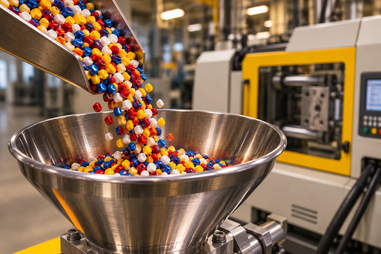
Injection Molding Color Mixing: From Streaks to Flawless Consistency
Nov 19, 2026
Master injection molding color mixing with expert guidance on colorant types, screw design, process parameters, defect troubleshooting, and Delta E QC protocols.
Read Article
Wrong Extruder Breaker Plate? Spot the Signs Before Scrap Piles Up
Nov 19, 2026
Learn how to select, size, and maintain your extruder breaker plate. Covers hole geometry, pressure drop, polymer-specific specs, and troubleshooting tips.
Read Article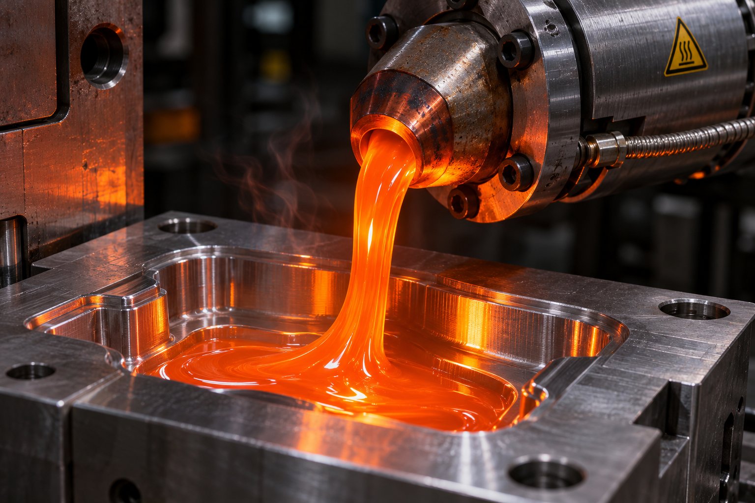
Injection Molding Melt Temperature: Why Your Barrel Settings Lie
Nov 19, 2026
Learn why barrel set points lie about injection molding melt temperature. Complete resin chart, measurement methods, defect troubleshooting, and optimization steps.
Read ArticleLooking for something else?
Search by material, symptom or product and jump straight to the relevant page.
These are navigation suggestions based on keyword matching — not a quotation, not a delivery commitment, and not a substitute for engineering review. Final specification is confirmed by our engineers against your drawings and processed material.
Need help with screw barrel selection?
Share your machine model, processed material and application. Our team can help with pricing and technical support.