

Understanding Voids in Injection Molding and Why They Matter
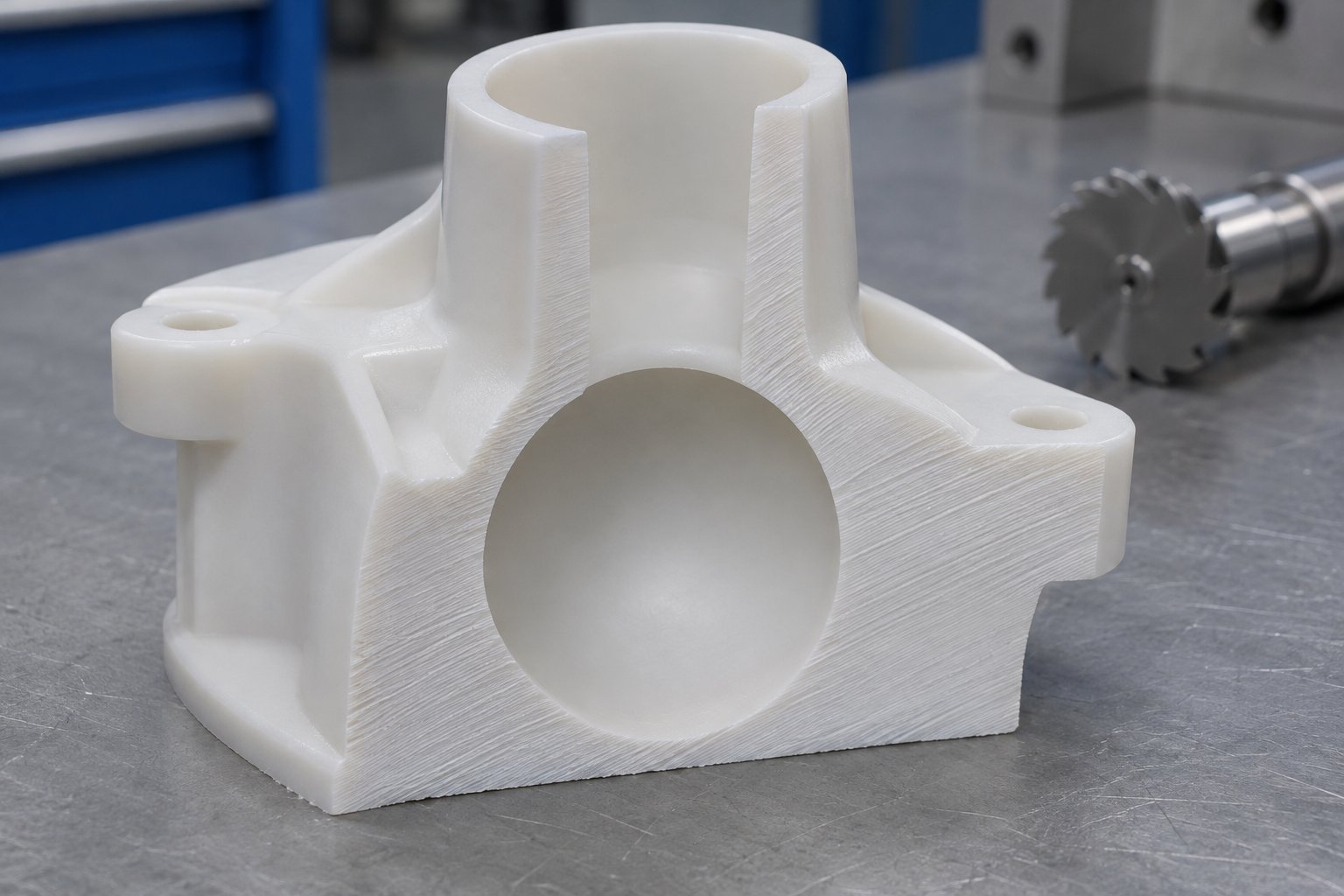
Imagine cutting a molded part in half and finding a hollow pocket buried deep inside the wall — invisible from the outside, undetectable by touch, yet silently undermining the part's strength. That hidden pocket is a void, and it represents one of the most deceptive defects in plastic manufacturing.
Voids in injection molding are internal cavities or gas pockets that form within the wall of a molded part during the cooling phase. Unlike surface blemishes, they are entirely concealed inside the part, making them difficult to detect without cross-sectioning, CT scanning, or ultrasonic inspection.
These internal flaws share a root cause with more visible defects like sink marks and blisters, yet they demand a fundamentally different diagnostic and corrective approach. Understanding exactly what they are — and why they behave differently from their surface-level cousins — is the first step toward eliminating them.
What Exactly Are Voids in Injection Molded Parts
When you cross-section a part that contains injection molding voids, you'll typically see spherical or elongated cavities concentrated in the thickest wall section. Picture the center of a chunky rib, a thick boss, or an area where two walls intersect. These are the zones where molten plastic takes the longest to cool and solidify, and that slow cooling is precisely what sets the stage for void formation.
From the outside, the part may look perfectly fine. The surface is smooth, dimensions check out, and color is uniform. That's what makes voids so insidious — they hide. A part can pass visual inspection and even basic dimensional checks while harboring internal cavities that compromise its mechanical performance. Without destructive testing or advanced non-destructive methods like industrial CT scanning, these defects often go unnoticed until a part fails in the field.
Voids in injection molding fall into two broad categories, each driven by a completely different mechanism:
- Vacuum voids — formed when the solidifying outer skin traps a still-molten core that continues to shrink, pulling the material apart from the inside and leaving a cavity under negative pressure.
- Gas voids — formed when trapped air, moisture-generated steam, or volatile gases become sealed inside the melt, creating pressurized bubbles within the part wall.
Recognizing which type you're dealing with changes everything about how you fix it. Applying a gas-void solution to a vacuum-void problem — or the reverse — wastes time, material, and machine hours.
Why Voids Deserve Immediate Attention
Internal cavities act as stress concentrators. Under load, the material around a void bears disproportionate stress, which leads to a cascade of performance problems: reduced tensile strength, lower impact resistance, shortened fatigue life, and a heightened risk of sudden fracture in structural or pressure-bearing applications. In safety-critical industries like automotive and medical devices, even a single void in the wrong location can trigger a part rejection or, worse, a field failure.
Here's a relationship that clarifies why voids, sink marks, and blisters often get confused — all three originate from the same volumetric shrinkage that occurs as molten plastic cools. The difference lies in how the outer skin responds to that shrinkage:
- Sink mark: The outer skin is still warm and pliable enough to collapse inward, creating a visible surface depression.
- Void: The outer skin has already solidified into a rigid shell, so the shrinking core pulls apart internally, forming a hidden cavity.
- Blister: A subsurface void — often gas-filled — later expands outward when the part is exposed to heat, pushing the skin into a raised bubble.
This trio shares the same family tree, but each branch requires its own corrective strategy. Treating a void like a sink mark, or ignoring a blister as purely cosmetic, leads to recurring quality issues. The path to a real fix starts with accurate identification — and that means understanding the science behind how each void type actually forms.
The Science Behind Void Formation in Plastic Parts
Knowing that voids exist inside your parts is one thing. Understanding exactly why they form — at the molecular and thermal level — gives you the diagnostic leverage to actually fix them. Voids in plastic injection molding trace back to two fundamentally different physical mechanisms, and confusing the two is the single most common reason troubleshooting stalls. One is driven by shrinkage and internal tension. The other is driven by gas and internal pressure. Let's break each one down.
How Volumetric Shrinkage Creates Vacuum Voids
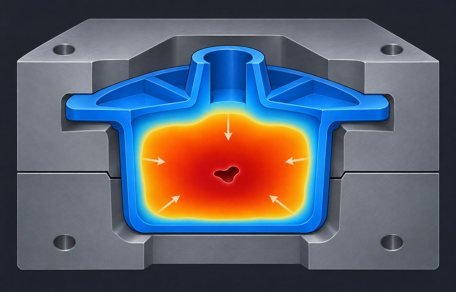
Picture what happens the instant molten polymer contacts the cooler mold wall. The outermost layer of plastic begins to solidify almost immediately, forming a rigid skin. Meanwhile, the material deeper inside the wall — the core — remains molten and continues to cool at a much slower rate. This creates what engineers call a freeze front: a boundary that progresses steadily inward from the mold surface toward the center of the part.
As that core cools, it contracts. All polymers undergo volumetric shrinkage as they transition from a molten to a solid state, and semi-crystalline materials like polypropylene, nylon, and PBT shrink especially aggressively because their molecular chains organize into tightly packed crystalline structures during solidification. Research into the pressure-volume-temperature (P-V-T) behavior of semi-crystalline polymers confirms that the crystallization process releases latent heat while simultaneously driving pronounced volume reduction — a combination that makes these resins particularly vulnerable to internal void formation.
Here's where the problem crystallizes — literally. The outer skin has already locked into a rigid shell, so it cannot collapse inward to accommodate the shrinking core. Instead, the still-molten interior material experiences growing internal tensile stress. When that tensile stress exceeds the melt strength of the softened core, the polymer physically pulls apart from itself, creating a smooth-walled internal cavity under negative pressure. That cavity is a vacuum void.
Several factors amplify this mechanism:
- Wall thickness: Thicker sections mean the freeze front takes longer to reach the core, giving shrinkage more time and volume to accumulate before the material fully solidifies.
- Differential cooling rates: When the outer skin freezes quickly but the core remains molten for an extended period, the mismatch in contraction rates intensifies the internal tension.
- High mold shrinkage resins: Semi-crystalline polymers with elevated crystallinity — think polypropylene, PA66, or POM — generate greater volumetric change during solidification than amorphous alternatives, making them inherently more prone to vacuum voids.
- Insufficient packing: If the packing phase cannot force enough additional melt into the cavity to offset shrinkage before the gate freezes, the core is left to shrink with no material to replace the lost volume.
The result is a void that forms in the geometric center of the thickest cross-section — the last region to solidify and the area furthest from any compensating pressure source. You'll rarely find a vacuum void near the surface or close to a gate. It lives deep in the core, right where you'd least expect to look without cutting the part open.
How Trapped Gas Creates Internal Bubbles
Gas voids originate from an entirely different mechanism. Instead of material pulling apart under tension, a gas bubble becomes trapped or generated inside the melt stream, and that pressurized pocket gets sealed into the part as the plastic solidifies around it. Three primary sources feed this type of defect:
- Entrapped air: During cavity fill, air that was already inside the mold must be displaced and evacuated through vents. If the flow front advances too rapidly, traps air against a blind rib, or converges from multiple directions without an escape path, pockets of air get encapsulated within the melt. These tend to show up in last-to-fill zones, deep bosses, and areas with poor venting.
- Moisture vaporization: Hygroscopic resins — polycarbonate, nylon, PET, and others — absorb atmospheric moisture during storage and handling. When that moisture-laden material hits barrel temperatures exceeding 200 degrees, the water flash-vaporizes into steam. Those steam bubbles get carried along with the melt and become sealed inside the part wall. This is one of the most frequent and preventable sources of gas voids.
- Thermal degradation volatiles: When resin is exposed to excessive barrel temperatures, prolonged residence time, or high shear, the polymer chains can break down and release volatile gases. Certain additives, colorants, flame retardants, and recycled content with higher volatile loads also contribute to off-gassing during processing.
Unlike vacuum voids, gas voids don't favor the geometric center of the thickest section. Their location tracks the source of the gas. Moisture-driven bubbles may appear anywhere along the flow path, often showing as streaky clusters or distributed irregularly. Air-entrapment voids concentrate in poorly vented ribs, near weld lines, or at the last-to-fill location. Degradation-driven voids may appear near the gate where material has spent the longest time in the hot barrel and runner system.
The internal character of the void differs, too. A gas void often has an irregular shape with rough or slightly discolored interior walls — sometimes even showing a sooty or brownish tinge from combustion of trapped air or degraded material. Contrast that with the smooth, clean, roughly spherical interior of a vacuum void, and you have a visual signature that an experienced molder can read during cross-section inspection.
Why the Distinction Changes Everything
Here's the practical payoff for understanding these two mechanisms. Imagine you've cut open a thick-walled nylon part and found voids in the core. Your instinct might be to increase pack pressure — a textbook response. But what if those voids are actually gas bubbles caused by insufficiently dried resin? Cranking up pack pressure won't drive moisture out of the melt. You'll burn through machine time, stress the tool, and the voids will still be there shot after shot.
The reverse scenario is equally wasteful. If the voids are vacuum-driven — caused by the core shrinking away from the frozen skin — no amount of improved venting or drying will solve the problem. The fix lies in extending effective packing, optimizing gate design, or reducing wall thickness.
Misidentifying the void type is the most expensive mistake in injection molding troubleshooting — it sends you down the wrong corrective path entirely.
This diagnostic-first philosophy is the foundation for understanding how to avoid voids in injection molding effectively. Before touching a single process parameter, classify the defect. Is internal tension pulling the material apart, or is internal pressure inflating a gas pocket? The answer to that question dictates every corrective step that follows — from material handling adjustments to packing-phase changes to mold modifications. Without it, you're guessing. And guessing is precisely what this systematic approach is designed to eliminate.
The challenge, of course, is that classification requires a reliable method — one that works on the production floor without expensive lab equipment. A practical side-by-side comparison of the two void types, along with a fast diagnostic test you can perform with nothing more than a heat gun, offers exactly that kind of actionable clarity.
Vacuum Voids vs Gas Voids and How to Tell Them Apart
Two defects, two opposite physical mechanisms, one shared name. That ambiguity is what causes voids in injection molding to be so frequently misdiagnosed. Vacuum voids and gas voids look similar on a CT scan thumbnail, but they behave differently under stress, appear in different regions of the part, and — critically — respond to completely different corrective actions. Telling them apart before adjusting any machine setting is the single highest-leverage step in the entire troubleshooting process.
The table below consolidates every distinguishing characteristic into one reference. Bookmark it, print it, tape it to the press — however you use it, make sure this comparison is the first thing your team consults when injection molding internal voids show up in a part.
| Dimension | Vacuum Void | Gas Void |
|---|---|---|
| Typical Appearance | Smooth-walled, roughly spherical or slightly elongated cavity; clean interior with no discoloration | Irregularly shaped bubble; interior walls may appear rough, sooty, brownish, or slightly discolored from burn marks or degradation |
| Common Location | Centered in the thickest wall section — the geometric core farthest from the mold surface and gate | Near last-to-fill zones, poorly vented ribs, deep bosses, weld-line convergence points, or scattered along the flow path (moisture-driven) |
| Root Cause Mechanism | Volumetric shrinkage of the molten core after the outer skin has solidified; internal tensile stress exceeds melt strength, pulling the material apart under negative pressure | Trapped air from inadequate venting, flash-vaporized moisture from undried hygroscopic resin, or volatile off-gassing from thermal degradation or additives — all creating a pressurized gas pocket sealed inside the melt |
| Internal Pressure | Negative (vacuum) — the cavity is under less-than-atmospheric pressure | Positive — the gas pocket pushes outward against the surrounding polymer |
| Heat-Gun Diagnostic Result | Surface draws inward (sinks) when heated — atmospheric pressure pushes the softened skin into the vacuum cavity | Surface blisters outward (inflates) when heated — the trapped gas expands and pushes the softened skin away from the part |
| Primary Corrective Actions | Increase packing pressure and hold time; verify gate seal; enlarge gate or runner to extend packing reach; improve cooling uniformity; core out thick sections to reduce wall thickness | Dry resin to grade specification; improve mold venting at last-to-fill locations; increase back pressure during screw recovery; reduce melt temperature or residence time to prevent degradation; check decompression settings |
| Resins Most Affected | Semi-crystalline resins with high volumetric shrinkage — PP, PA6, PA66, POM, PBT — especially in thick-wall geometries | Hygroscopic resins prone to moisture absorption — PC, PA6, PA66, PET, PBT — and resins processed with volatile additives, flame retardants, or high-percentage regrind |
| Related Surface Defects | Sink marks (same shrinkage mechanism, but the skin collapses inward instead of maintaining its shape) | Splay / silver streaks (moisture- or degradation-driven gas escaping along the flow front); blisters (subsurface gas void expanding under post-mold heat exposure) |
Keep this comparison handy, because the corrective actions in the two columns are nearly opposite. Raising pack pressure is the go-to fix for vacuum voids — but applying that same adjustment to a gas void won't push the gas out of the melt. Improving venting solves air-entrapment gas voids — but it has zero effect on a shrinkage-driven vacuum cavity buried in a thick core. The table above is your map; the diagnostic techniques below are your compass.
Visual Differences Between Vacuum Voids and Gas Voids
When you cross-section a part through the defect area, the interior of the void tells a story. Vacuum voids present as clean, smooth-walled cavities — almost polished-looking under magnification. The walls are glossy because the polymer was simply pulled apart by tensile forces while still in a semi-molten state. There's no foreign substance, no residue, no discoloration. These cavities tend to be roughly spherical or gently elongated in the flow direction, and they sit squarely in the thickest region of the cross-section, right at the thermal center where the material solidified last.
Gas voids, by contrast, often look rougher and more chaotic. Picture an irregularly shaped pocket — sometimes almost jagged — with walls that may carry a brownish, yellowish, or sooty tinge. That discoloration is a telltale sign. Trapped air compressed ahead of the advancing melt front can reach extreme temperatures through adiabatic compression, scorching the surrounding polymer. Moisture-driven bubbles may leave a subtler mark, but the interior surface still tends to look less uniform than a vacuum void's clean shell. When you see rough or discolored internal walls, the evidence points strongly toward a gas source rather than shrinkage.
Location adds another diagnostic layer. Found a single void dead-center in the fattest wall section? That's the classic vacuum-void fingerprint. Found multiple smaller bubbles clustered near a blind rib tip, at a weld-line junction, or scattered along the flow path? Gas bubbles tend to appear at flow ends or junctions, often several at once, because they track the path of the trapped gas rather than the geometry of the shrinkage gradient.
Here's the cross-section procedure in practice:
- Cut the part through the suspected void area using a band saw or a microtome for higher precision.
- Examine the interior cavity surface under magnification — even a 10x loupe is sufficient for initial classification.
- Smooth, clean, glossy walls = vacuum void (shrinkage-driven, negative pressure).
- Rough, discolored, sooty, or irregular walls = gas void (trapped air, moisture, or degradation volatiles).
- Note the void's position relative to wall thickness — centered in the thickest section or off-center toward a vent, rib, or last-to-fill zone.
This five-step visual check takes minutes and immediately narrows your corrective path. But for situations where you need a faster answer — or can't afford to sacrifice a part — there's an even quicker field test.
The Diagnostic Short-Circuit Test
Experienced process engineers have used a simple heat-gun diagnostic for decades to classify injection molding defects voids without any lab equipment. The principle is straightforward: vacuum voids and gas voids respond in physically opposite ways when the surrounding polymer is softened by localized heat.
Here's how to perform the test, as referenced in industry training based on Bozzelli's methodology:
- Select a freshly molded part — ideally within a few hours of production, before any post-mold environmental changes can alter the internal conditions.
- Identify the void location — use prior cross-sections, CT scan data, or the part's known thick-wall geometry to pinpoint where the defect sits.
- Apply gentle, localized heat with a heat gun to the surface directly above the void. Warm the area slowly until the wall begins to soften. You're not trying to melt the part — just bring the skin above its heat deflection temperature in that local zone.
- Observe the surface response:
- Surface draws inward (sinks): Atmospheric pressure is pushing the softened skin into a low-pressure cavity. The void is under negative pressure — it's a vacuum void. Your corrective focus belongs on packing, gate seal, cooling, and wall-thickness design.
- Surface blisters outward (inflates): Internal gas pressure is pushing the softened skin away from the part. The void contains trapped gas — it's a gas void. Your corrective focus belongs on material drying, venting, back pressure, and barrel temperature management.
Two opposite responses, two completely different corrective paths. This test takes less than three minutes and prevents the classic troubleshooting mistake: chasing packing parameters when the real problem is moisture, or overhauling vent depths when the real problem is shrinkage.
There's one important complication to be aware of. Hygroscopic resins like polycarbonate, nylon, and PET can exhibit both void types simultaneously in the same part. Imagine a thick-walled PC housing that was molded from insufficiently dried resin. The thick sections generate vacuum voids from shrinkage, while the residual moisture generates gas voids from flash-vaporized steam — and both defects coexist within the same cross-section. When you heat-test the surface, you might see a blister at one location and a sink at another, or an ambiguous response where competing pressures partially cancel each other out.
This dual-mechanism scenario makes the diagnostic step especially critical for hygroscopic materials. If you stop at the first positive identification — "it's a gas void, so I need to dry better" — you may fix the moisture problem only to discover vacuum voids still lurking in the core. The safest approach with these resins is to cross-section multiple samples, perform the heat test at several locations, and treat both void types as probable until evidence rules one out.
Accurate classification is the gateway to efficient correction, but correction itself has layers. The most accessible layer — and the one where gas voids are most preventable — is material preparation. How you store, dry, and handle resin before it ever reaches the barrel determines whether moisture-driven gas bubbles are a persistent headache or a non-issue entirely.
Material Preparation and Drying to Prevent Gas Voids
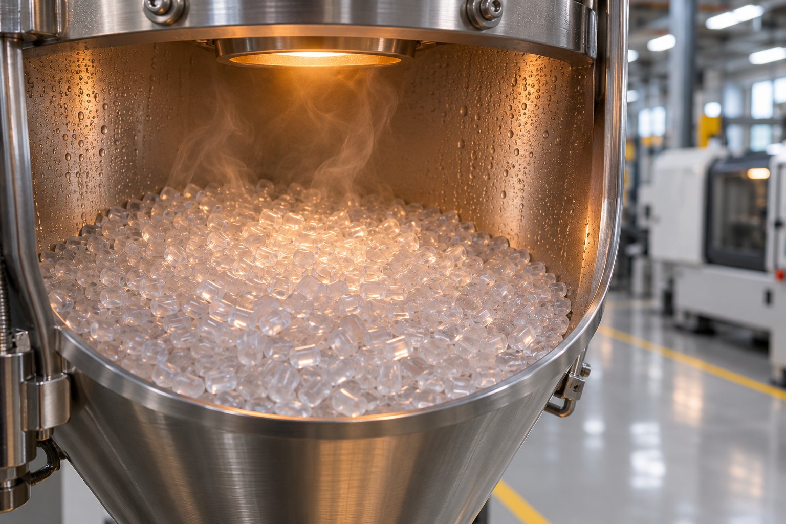
You've identified the void type. The heat-gun test confirmed a blister — gas pressure pushing outward — and cross-sectioning revealed rough, slightly discolored interior walls scattered along the flow path. The diagnosis points squarely to a gas void. So where do you look first? Not at the machine. Not at the mold. You look at the material sitting in the hopper.
Resin preparation is the most overlooked and most preventable contributor to gas-type voids in injection molding. Moisture-related gas bubbles account for a disproportionate share of injection molding troubleshooting voids cases, and the frustrating part is that they're entirely avoidable — if the material is handled correctly before it ever touches the barrel.
Hygroscopic Resins and the Moisture-Void Connection
Here's the mechanism in simple terms. Hygroscopic polymers have a molecular affinity for water — they literally absorb moisture from the surrounding air during storage, transport, and handling. When that moisture-laden resin enters the heated barrel, the water trapped within the pellets flash-vaporizes into steam at processing temperatures. Those steam pockets get carried along with the melt stream, sealed inside the part wall as the plastic solidifies, and become the gas voids you find during inspection.
Think of it like dropping a wet sponge into a frying pan. The water doesn't just sit there — it erupts into vapor instantly. Inside a barrel running at 250 to 300+ degrees Celsius, even a few hundredths of a percent of excess moisture can generate enough steam to riddle an injection molding part with internal void defects.
Not every resin carries the same risk. Hygroscopic resins — those that actively absorb moisture into their molecular structure — demand the most aggressive drying protocols. Non-hygroscopic materials carry surface moisture only, which is easier to remove and less likely to cause severe problems. Here's how common resins break down by void susceptibility:
- High risk (hygroscopic, aggressive drying required): Nylon (PA6, PA66), polycarbonate (PC), PET, PBT. These resins absorb moisture deep into the pellet structure and require thorough desiccant drying to reach safe processing levels. They also face a double-risk scenario — nylon and PBT are semi-crystalline with high volumetric shrinkage, making them vulnerable to both gas voids from moisture and vacuum voids from crystalline shrinkage in thick-walled parts. Polycarbonate bubble void causes often trace directly to air vs moisture confusion during diagnosis, since PC is amorphous yet highly hygroscopic.
- Medium risk (hygroscopic, moderate drying required): ABS, PMMA (acrylic), TPU. These resins absorb less aggressively than the high-risk group but still require dedicated drying — particularly in humid climates or during summer months when ambient moisture levels spike.
- Lower risk (non-hygroscopic, surface moisture only): Polyethylene (PE), polypropylene (PP), polystyrene (PS). These materials don't absorb moisture into the pellet itself, but surface condensation can still occur — especially when cold resin is brought into a warm, humid production environment. A brief drying cycle or proper climate-controlled storage typically handles the issue.
The critical takeaway? Even resins in the "lower risk" group aren't immune. A bag of polypropylene pellets pulled from a cold warehouse into a hot, humid plant floor can accumulate enough surface condensation to introduce gas bubbles. Climate and storage conditions matter just as much as the resin's inherent moisture behavior.
Proper drying demands the right equipment, not just the right intention. For hygroscopic resins, desiccant dryers are essential — they regenerate their drying media and deliver consistently low dew-point air to the hopper, pulling moisture out of the pellets reliably. Standard hot-air dryers, by contrast, simply blow heated ambient air over the resin. On a humid day, that air may carry significant moisture of its own, making the dryer ineffective or even counterproductive for hygroscopic materials.
Here's the mistake that catches experienced molders just as often as newcomers: relying solely on dryer time settings rather than verifying actual moisture content. Resin manufacturers provide recommended drying times and temperatures, but those recommendations assume a starting moisture level that may not match reality — especially in humid regions or during seasonal weather shifts. Using a moisture analyzer to confirm that the resin meets specification before processing is the only reliable safeguard. A molder who assumes the material is dry because the timer says so is guessing — and guessing is exactly what produces recurring void defects.
One more caution: over-drying isn't harmless. Certain resins — particularly nylon and PET — can degrade or discolor when exposed to excessively high drying temperatures or prolonged drying times beyond the manufacturer's recommendation. Over-dried nylon, for instance, can experience molecular chain scission, reducing viscosity and mechanical properties. The goal is to land in the specified moisture window, not to drive moisture to absolute zero at any cost.
Beyond Drying — Filler Content and Volatile Additives
Moisture is the most common gas-void culprit, but it's not the only one. The composition of the resin compound itself can introduce volatile gases during processing, even when the base polymer is perfectly dry.
Glass-fiber and mineral-filler reinforcements change the shrinkage equation in ways that directly influence void patterns. Filled resins shrink less in the flow direction because the rigid filler particles resist contraction along the alignment axis. That's generally beneficial for dimensional stability. However, voids can still form at the filler-matrix interface — the boundary where the glass fiber or mineral particle meets the surrounding polymer. During cooling, differential thermal contraction between the stiff filler and the shrinking resin can create micro-separations at these interfaces, resulting in a pattern of small, distributed voids rather than one large central cavity.
Additives introduce a subtler risk. Certain colorants, flame retardants, and processing aids contain volatile components that can off-gas at melt temperatures, generating small gas pockets within the melt stream. The effect is typically minor with virgin, high-quality compounds — but it escalates quickly when you introduce:
- Recycled or regrind content — previously processed material that may have undergone partial thermal degradation, increasing its volatile load. Higher regrind percentages amplify the risk.
- Flame retardant packages — some halogenated and phosphorus-based systems release gases at elevated barrel temperatures, particularly if processing conditions push toward the upper limits of the recommended range.
- Low-quality colorant concentrates — carrier resins or pigment dispersions with higher volatile content can contribute gas that the base resin alone would not produce.
When gas voids persist despite verified drying and good venting, these compound-level factors deserve investigation. Request a volatile content analysis from your material supplier, review the percentage of regrind in the blend, and evaluate whether processing temperatures are driving off-gassing from additive packages.
Material preparation is the first and most accessible layer of void prevention — the one that costs the least to get right and the most to get wrong. But even perfectly dried, properly compounded resin can still produce voids if the process parameters that govern how that material fills, packs, and cools inside the mold aren't dialed in. The packing phase, in particular, is where vacuum voids are either prevented or guaranteed.
Process Parameter Optimization to Eliminate Voids
Every injection molding void is born — or prevented — during a handful of seconds inside the mold. Material preparation eliminates one entire class of gas-driven defects before the cycle even starts, but the process parameters that govern filling, packing, and cooling determine whether the remaining void risks become real defects or theoretical ones. The challenge is that adjusting a parameter to fix one void type can actually worsen the other. Raising melt temperature, for instance, may extend the packing window and reduce vacuum voids — while simultaneously increasing the risk of thermal degradation and gas voids.
The table below maps each major process variable to its directional effect on both vacuum voids and gas voids. Use it as a quick-reference guide before making any adjustment, so you're always moving the right lever in the right direction for the void type you've diagnosed.
| Process Variable | Direction of Adjustment | Effect on Vacuum Voids | Effect on Gas Voids |
|---|---|---|---|
| Packing Pressure | Increase | Strong improvement — forces additional melt into the cavity to compensate for volumetric shrinkage in the core | Minimal direct effect — does not remove gas from the melt, though better packing can compress small gas pockets slightly |
| Pack/Hold Time | Increase (up to gate seal) | Strong improvement — extends the duration of active shrinkage compensation before gate freeze-off | Minimal effect — gas trapped in the melt is not expelled by extended hold time |
| Melt Temperature | Increase (moderate) | Moderate improvement — lower melt viscosity extends packing reach and delays gate freeze | Potential worsening — higher barrel temps increase degradation risk and volatile off-gassing |
| Mold Temperature | Increase | Moderate improvement — slows skin solidification, allowing the pack phase to compensate deeper into thick sections | Minimal effect on gas source, though slower freezing may allow some gas migration toward vents |
| Cooling Time | Increase | Indirect improvement — ensures part is fully solidified before ejection, preventing post-mold void expansion | Indirect improvement — prevents premature ejection that could cause subsurface gas pockets to expand into blisters |
| Injection Speed | Optimize (moderate) | Indirect — too slow causes premature freeze-off, reducing packing effectiveness; too fast can overshoot and cause other defects | Direct impact — too fast creates jetting and turbulence that traps air; too slow allows hesitation marks and air pockets |
| Back Pressure | Increase (moderate) | Minor improvement — better melt homogeneity improves flow and packing consistency | Direct improvement — compresses air out of the melt during screw recovery, reducing entrapped gas |
| Decompression (Suck-Back) | Reduce or eliminate | Minimal effect | Direct improvement — excessive decompression pulls air into the nozzle tip, introducing gas into the next shot |
Notice the pattern: packing-related variables are your primary weapons against injection molding vacuum voids, while material-handling and melt-preparation variables target gas voids. With that map in hand, let's drill into the three most impactful parameter groups.
Packing Pressure and Pack Time — The Primary Vacuum-Void Defense
The packing phase is where injection molding voids sinks and internal cavities are either compensated or locked in. Here's what happens: after the cavity fills, the machine switches from velocity-controlled injection to pressure-controlled packing. During this phase, pack pressure pushes additional melt into the cavity to replace the volume lost as the plastic cools and shrinks. Every polymer contracts during solidification — semi-crystalline resins like nylon and polypropylene shrink aggressively — and if the packing phase can't keep up with that contraction, the still-molten core pulls apart, creating a vacuum void.
Two variables control the effectiveness of packing: the magnitude of the pressure and the duration it remains active.
Pack pressure magnitude needs to be high enough to overcome the flow resistance of the cooling, increasingly viscous melt channel between the gate and the core of the part. Too low, and the pressure at the cavity drops below what's needed to compensate for shrinkage. Too high, and you risk flash, excessive residual stress, or sticking. Many experienced molders use profiled packing — a stepped or ramped pressure curve that starts high to fill the last few percent of the cavity and then tapers to maintain compensation without overpacking near the gate while the far end of the part is still shrinking.
A 2025 study on sink voids in thick-walled thermoplastic parts found that at the end of the packing phase, a thick-walled gauge plate had a frozen layer fraction of only about 50% — meaning half of the part's volume solidified without pressure compensation. That massive uncompensated volume created the differential shrinkage that drove void formation. The finding underscores a hard reality for injection molding voids thick parts: beyond a certain wall thickness, even aggressive packing cannot reach the core before the gate freezes shut.
Pack time is equally critical — but only up to a point. Packing remains effective only as long as the gate stays open. Once the gate freezes (solidifies), no additional melt can enter the cavity, and any further hold time simply wastes cycle time and stresses the machine. This is where the gate-seal study becomes essential.
A gate-seal study is a systematic test used in scientific molding to determine exactly when the gate freezes. You mold sets of parts at progressively increasing hold times — say 1, 2, 3, 4, and 5 seconds — while keeping all other parameters constant. After each set, you weigh the parts. As long as the gate is still open, increasing hold time pushes more material into the cavity, and part weight rises. The moment part weight plateaus — stops increasing with additional hold time — the gate has sealed. That plateau marks the optimal pack time: long enough to fully compensate for shrinkage, short enough to avoid wasting cycle time.
Gate geometry directly governs this timing. A small, thin gate freezes faster, cutting off the packing window earlier and limiting how much shrinkage you can compensate. A larger or thicker gate stays open longer, extending packing reach — but it also leaves a bigger gate vestige and may require longer cooling. For parts with thick walls that are prone to injection molding void defects, gate sizing is often the quiet bottleneck: the process engineer dials in textbook pack pressure and hold time, but the gate freezes before that pressure ever reaches the core. Enlarging the gate — or relocating it closer to the thickest section — can unlock packing effectiveness that no amount of pressure increase can achieve through a frozen gate.
Temperature and Cooling Adjustments
Temperature settings affect void formation through two competing mechanisms: they influence how long the melt remains packable, and they influence whether the melt degrades and generates gas. Getting the balance right requires knowing which void type you're fighting.
Melt temperature controls the viscosity of the polymer as it flows through the gate and into the cavity during packing. A moderately higher melt temperature lowers viscosity, allowing the pack pressure to transmit further into the part and delaying gate freeze-off. For vacuum voids in thick sections, that extended packing window can make the difference between a void-free core and a hollow one. The same Taguchi-based study mentioned above identified melt temperature as the most significant factor influencing volumetric shrinkage variation in thick-walled nylon parts — more influential than packing pressure, packing time, or injection time.
The trade-off? Pushing melt temperature higher also increases the risk of thermal degradation, especially with heat-sensitive resins like PVC, POM, or PC. Degradation breaks polymer chains and releases volatile gases — the exact mechanism that produces gas voids. If you're already fighting gas-type defects, raising barrel temperatures is counterproductive.
Mold temperature influences how quickly the outer skin solidifies. A higher mold temperature slows down skin formation, which does two valuable things for vacuum-void prevention: it keeps the gate open longer (delaying freeze-off) and allows the freeze front to progress more uniformly from the outside in, reducing the sharp thermal gradient between the rigid skin and the molten core. For injection molding voids thick parts, a warmer mold is often more effective than higher pack pressure alone, because it addresses the root cause — differential cooling — rather than just the symptom.
The cost is cycle time. Slower cooling means longer time before the part is rigid enough to eject. In production environments where cycle time is tightly controlled, this trade-off needs to be evaluated against the cost of void-related scrap and rejects.
Cooling time itself serves as a safeguard. Ejecting a part before the core has fully solidified can allow residual internal stress to expand a nascent void after removal, or permit a subsurface gas pocket to inflate into a blister when ambient heat softens the skin. Extending cooling time — particularly for heavy-walled parts — ensures that the part leaves the mold with its internal structure fully set.
Injection Speed and Back Pressure
Injection speed and back pressure sit at the intersection of both void types, making them versatile — and easily misadjusted — parameters.
Injection speed primarily affects gas-type voids through its influence on air entrapment during fill. When the screw pushes melt into the cavity too fast, the flow front can break apart in a phenomenon called jetting — the melt shoots through the gate as a free stream rather than advancing as a uniform front. That jetting action folds air into the melt, trapping pockets that become sealed gas voids. In parts with abrupt cross-section changes, high speeds can also create turbulence at the transition point, entrapping air at rib bases or boss entries.
Too slow is equally problematic, though for different reasons. A sluggish fill allows the advancing melt front to hesitate and cool prematurely, creating frozen skin patches in the flow channel that reduce the effective cross-section for packing. That premature freeze-off undermines the pack phase the same way an undersized gate does — the pressure simply can't reach the core. The sweet spot is a fill speed that maintains a smooth, uniform flow front without jetting or hesitation, typically determined through a viscosity curve study at the start of process development.
Back pressure during screw recovery is one of the most underused tools for gas-void prevention. When the screw rotates to meter the next shot, back pressure resists the screw's rearward movement, compressing the melt more thoroughly. This compression does two things: it improves melt homogeneity by enhancing mixing and thermal uniformity, and it squeezes entrapped air out of the melt stream. Low back pressure allows air pockets to remain in the shot — air that then gets injected into the cavity and sealed into the part as gas voids.
Increasing back pressure moderately is a low-risk, high-reward adjustment for reducing scattered gas voids. Excessive back pressure, however, generates unnecessary shear heat, which can degrade sensitive resins and circle back to the volatile off-gassing problem. As with every parameter in this process, the correction is directional, not absolute — and it must be calibrated to the specific resin, part geometry, and void type you've diagnosed.
Process parameters give you powerful control over injection molding void formation — but they operate within boundaries set by the mold itself. Cooling channel placement, vent design, wall thickness geometry, and gate location all define how effectively those optimized parameters can do their job. When process adjustments alone plateau short of eliminating voids, the mold's design is usually the ceiling you've hit.
Mold Design and Cooling Factors That Drive Void Formation
You've dialed in drying, optimized packing pressure, fine-tuned melt temperature, and verified back pressure — yet voids persist. The process is doing everything it can. The problem is that it's working inside a mold that was never designed to let those parameters succeed. Cooling channels that can't reach hot spots, walls too thick for any packing profile to penetrate, and vents too shallow to evacuate trapped air all create structural ceilings that no amount of process tweaking can break through. When troubleshooting voids injection molding on the production floor, the mold itself is often the final — and most stubborn — root cause layer.
Wall Thickness Design and Its Direct Impact on Voids
If there's one design variable that predicts void risk more reliably than any other, it's wall thickness. Thick sections are where plastic injection molding voids overwhelmingly concentrate, and the physics behind this relationship is straightforward: a thicker wall means the freeze front takes longer to reach the core, the molten center shrinks for a longer duration without pressure compensation, and the resulting internal tension has more volume to pull apart.
Think of it as a race between the packing phase and the gate. Packing pressure is trying to push additional melt into the cavity to replace shrinking volume. The gate, meanwhile, is solidifying — and once it freezes, the race is over. In a thin-walled part, the core solidifies quickly and the required shrinkage compensation is modest. In a thick-walled part, the core stays molten well beyond gate seal, leaving a massive volume of material to contract with no incoming melt to replace it. A 2025 study on thick-walled thermoplastic parts found that at the end of the packing phase, roughly half the wall thickness was still unfrozen — meaning that entire inner volume solidified and shrank without any pressure compensation at all.
Beyond a certain thickness-to-flow-length ratio, packing pressure simply cannot reach the core before the gate seals, regardless of how aggressively you set the process. That's the structural ceiling — and it's why part design, not process adjustment, is the correct response when thick sections are the root cause of a void defect injection molding.
When thick sections are functionally unavoidable, several design-level strategies can reduce void risk without sacrificing the part's structural intent:
- Core out material: Hollow out the interior of thick junctions, bosses, and mounting pads to bring the effective wall closer to the nominal thickness. Industry guidance on wall thickness emphasizes that coring is one of the most effective methods for avoiding the sink, void, and warpage chain reaction that thick sections trigger.
- Redesign ribs and gussets: Instead of relying on a solid thick section for stiffness, distribute the load across thinner ribs. Rib thickness should generally stay below 60% of the adjoining nominal wall — dropping to 40% for cosmetically critical surfaces — with rib height limited to roughly three times the rib's own thickness. These proportions keep the rib-wall junction thin enough to pack effectively while still adding meaningful stiffness.
- Gas-assist molding: For parts that genuinely require thick, solid-looking sections, gas-assist channels can hollow out the core from the inside during molding, eliminating the shrinkage-driven tensile stress that causes vacuum voids. The gas displaces the still-molten core, leaving a structurally efficient hollow cross-section.
- Gradual transitions: Abrupt thickness changes — a thin wall stepping directly into a thick boss or pad — create localized shrinkage mismatches that concentrate voids at the transition. A commonly cited guideline suggests that a thinner wall should run no less than 40% to 60% as thick as the adjacent wall it connects to, with the transition tapered over a distance rather than stepped abruptly.
The principle is consistent: keep wall thickness as uniform as practical, and where thick regions are unavoidable, reduce the effective thermal mass that the packing phase must compensate. Every millimeter of unnecessary thickness is another millimeter the freeze front has to traverse — and another opportunity for a void to form in the unreachable core.
Cooling Channel Placement and Differential Cooling
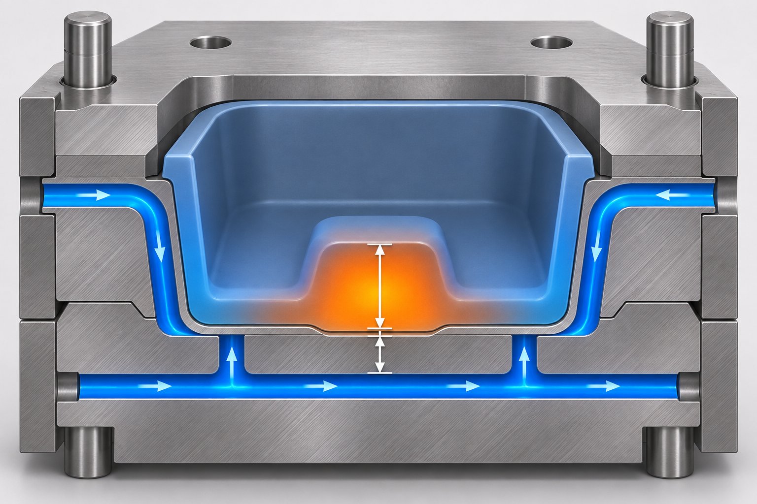
Imagine two sides of the same part: one backed by a cooling channel running 10 mm from the cavity surface, the other backed by a steel mass with no coolant anywhere nearby. The side with the channel freezes quickly, forming a rigid skin early. The side without the channel stays hotter, freezes later, and shrinks on a different timeline. That mismatch in cooling rate creates differential shrinkage — and differential shrinkage concentrates voids in the hotter zone, where the material contracts last and has no compensating pressure left to fill the gap.
This scenario is surprisingly common. Conventional cooling channels are drilled in straight lines, a manufacturing limitation that makes it difficult to follow complex cavity geometries closely. Deep cores, tall ribs, and geometrically intricate features often end up far from any cooling line, creating hot spots that extend the local cooling time well beyond the rest of the part. Research on conformal cooling channel optimization confirms that the distance from the channel center to the mold cavity wall is a key design variable directly influencing cooling time — and by extension, the uniformity of shrinkage across the part.
Several cooling-related issues contribute to void formation:
- Poorly placed cooling lines: Channels that are too far from the cavity surface, unevenly spaced, or absent near thick features leave hot zones where shrinkage goes uncompensated.
- Inadequately cooled cores: Core pins and tall core features are notoriously difficult to cool with conventional drilled channels. Without bubblers, baffles, or dedicated core cooling circuits, these areas become thermal bottlenecks.
- Asymmetric mold halves: When the cavity side cools faster than the core side — or vice versa — the part develops a thermal gradient through its thickness. The hotter side shrinks later and more, pulling voids toward that surface.
Conformal cooling has emerged as an advanced solution for geometries where straight-drilled channels simply can't deliver uniform heat extraction. Unlike conventional channels, conformal circuits follow the contour of the cavity surface, maintaining a consistent distance from the mold wall even around curves, deep pockets, and complex features. The same conformal cooling study demonstrated that an optimized series flat-head conformal layout shortened the injection molding cycle by over 62% compared to conventional straight channels — a dramatic improvement driven by faster, more uniform heat removal from deep-cavity geometry. While conformal channels require metal additive manufacturing (selective laser melting) for the mold insert, the payoff in cycle time reduction and cooling uniformity can be substantial for parts where differential cooling is driving void defects.
Even without conformal cooling, meaningful improvements are achievable. Adding baffles or bubblers to core pins, rebalancing coolant flow rates between circuits, reducing the distance between channels and the cavity surface where steel thickness allows, and ensuring turbulent flow inside the channels (rather than laminar flow, which transfers heat far less efficiently) all help close the thermal gap between hot spots and well-cooled areas.
Venting and Air Evacuation
Cooling and wall thickness influence vacuum voids. Venting, by contrast, directly targets a specific class of gas voids — those caused by air trapped inside the mold cavity during fill. As the melt front advances, it displaces the air that was already occupying the cavity. That air has to go somewhere. If the escape path is too small, blocked, misplaced, or completely absent, the gas compresses ahead of the flow front and becomes encapsulated in the part wall.
Where does that trapped air typically end up? In the locations where the flow front arrives last — and those are precisely the spots where poor venting manifests as burn marks, short shots, or internal voids. Blind ribs, deep bosses, and areas where multiple flow fronts converge are especially vulnerable, because the air has no remaining escape route once the melt surrounds it.
Air evacuates through several pathways in a properly vented mold:
- Parting-line vents: Shallow channels machined into the parting surface that allow air to pass but are too thin for molten plastic to enter. These are the primary venting mechanism for most molds.
- Ejector-pin clearances: The gap between ejector pins and their bores provides a secondary venting path, particularly useful for features on the core side of the part.
- Porous inserts: Sintered metal inserts with controlled porosity can be placed in blind pockets or deep ribs where conventional venting is impossible, allowing gas to permeate through the insert without creating flash.
An important distinction applies here. Voids from trapped air in the mold cavity are a venting issue — the gas was already in the cavity and wasn't evacuated during fill. Voids from gas in the melt — moisture steam, degradation volatiles, or air entrained during screw recovery — are a material or barrel issue. The two require completely different corrective actions. Improving venting solves the first problem but does nothing for the second. If cross-sectioning reveals gas voids near a gate rather than at last-to-fill areas, the source is likely the melt stream, not the cavity air.
Runner and gate design also play a dual role. During fill, an improperly designed runner system can trap air at sharp transitions, dead spots, or cold-slug wells that don't evacuate cleanly. After fill, gate geometry governs how effectively packing pressure reaches the cavity — a factor that directly influences vacuum voids, as discussed in the process parameter section. A gate that's too small freezes early, cutting off both air evacuation (during late fill) and pressure transmission (during pack). A gate positioned far from the thickest section forces the melt to travel a long, cooling path before reaching the area most in need of compensation.
To consolidate these mold-design principles into an actionable reference, here are the key practices that reduce void risk from the tooling side:
- Maintain uniform wall thickness wherever possible, targeting gradual transitions rather than abrupt steps between thick and thin sections
- Core out thick junctions, bosses, and pads to reduce the thermal mass that must be packed and cooled
- Size ribs at 40% to 60% of the adjoining wall thickness to prevent creating thick, hard-to-pack intersections
- Position cooling channels as close to the cavity surface as steel strength permits, with consistent spacing to minimize hot spots
- Use baffles, bubblers, or conformal cooling in deep cores and geometrically complex features that straight-drilled channels cannot reach
- Ensure turbulent coolant flow (adequate flow rate and channel diameter) for efficient heat transfer
- Place vents at every last-to-fill location, blind rib tip, deep boss, and weld-line convergence point
- Verify vent depth is appropriate for the resin — deep enough to evacuate air, shallow enough to prevent flash
- Inspect and clean vents regularly; residue buildup progressively restricts air evacuation over production runs
- Locate gates near the thickest wall section to maximize packing reach and minimize the distance pressure must travel through cooling melt
- Size gates large enough to delay freeze-off and maintain an effective packing window for thick-walled parts
Mold design sets the boundaries within which every process parameter operates. A well-cooled mold with proper venting and thoughtful wall-thickness control gives the process engineer room to eliminate voids through parameter adjustment alone. A poorly designed mold, on the other hand, creates conditions where no process setting can fully compensate — and the defect becomes baked into the tooling.
Yet even a well-designed mold depends on the machine delivering consistent, well-conditioned melt at the required pressures. The plasticizing unit — the screw, barrel, and check ring that prepare and inject the resin — is the mechanical link between your optimized process settings and the actual conditions inside the cavity. When that hardware wears or doesn't match the resin, the gap between what the process demands and what the machine delivers becomes another hidden source of voids.
Plasticizing Hardware Condition and Its Role in Void Defects
You've optimized drying, refined packing parameters, verified cooling uniformity, and confirmed your mold venting is clean and properly sized. The process looks textbook on the controller screen — yet voids keep showing up in cross-sections. What's left? The answer might be sitting right behind the nozzle: the plasticizing unit itself.
A worn or mismatched screw, barrel, or check ring is one of the most frequently overlooked contributors to void injection molding defects. Most troubleshooting guides jump straight to process settings and mold design, treating the plasticizing hardware as a fixed constant. In reality, these components degrade over time, and that degradation quietly erodes the machine's ability to deliver consistent, well-conditioned melt at the pressures your process demands. The result? Your optimized settings on the screen don't translate to optimized conditions inside the cavity — and voids persist no matter how many parameter adjustments you make.
How Screw and Barrel Wear Undermines Packing and Melt Quality
Think of the plasticizing unit as a precision pump. The screw melts, mixes, and meters the resin. The barrel provides the cylinder. The check ring (non-return valve) acts as a one-way seal, preventing melt from flowing backward during injection and packing. When any of these components wear beyond tolerance, that precision pump develops leaks, inconsistencies, and blind spots that directly feed both vacuum voids and gas voids.
Here's how each specific wear pattern creates problems:
- Check-ring leakage: This is the most impactful wear mechanism for void formation. During injection and packing, the check ring must seal tightly to prevent melt from flowing backward over the screw flights. A worn check ring — with eroded sealing surfaces, a worn seat, or a sluggish sliding ring — allows melt to leak back past the valve during the entire pack phase. The controller shows the set pack pressure, but the effective pressure reaching the cavity is significantly lower because material is bleeding backward with every packing pulse. The result is classic vacuum void behavior: the core shrinks, the packing can't compensate, and internal cavities form in thick sections. As industry analysis of worn plasticizing components confirms, a leaking check valve causes inconsistent shot size and degraded packing pressure — conditions that directly promote voids, sink marks, and short shots.
- Screw-flight wear: Over thousands of hours of processing — especially with glass-filled or mineral-filled resins — the outer edges of the screw flights erode. As flight diameter decreases, the clearance between the screw and barrel wall increases. That enlarged gap reduces the screw's compression capability, which does two damaging things: it decreases the mechanical work input needed to fully melt the resin (leaving unmelted or poorly mixed regions in the melt stream), and it allows material to slip backward over the flights during recovery, reducing metering consistency. Unmelted pellet fragments in the melt act as air-trapping nucleation points, contributing to gas voids. Inconsistent shot volume undermines the repeatability of your packing phase, contributing to vacuum voids.
- Barrel-bore enlargement: The barrel's inner diameter gradually increases with abrasive wear, particularly in the compression and metering zones. An enlarged bore compounds the effects of screw-flight wear — the clearance gap widens from both sides. Pressure transmission from the screw to the melt degrades, melt flow becomes less controlled, and the machine's ability to maintain consistent injection and packing pressures diminishes. A pressure-loss monitoring study emphasizes that changes in barrel diameter, screw type, and machine components are among the most common causes of unexpected pressure loss during injection molding — loss that shows up as short shots, sink marks, and voids near the end of fill.
Here's the insidious part: worn plasticizing components can completely mask your optimal process settings. Imagine a scenario where a process engineer identifies vacuum voids in a thick-walled nylon part and responds by increasing pack pressure. The controller dutifully ramps up hydraulic pressure. But a worn check ring is leaking 15% to 20% of the melt volume backward during pack, so only a fraction of that increased pressure ever reaches the cavity. The voids persist. The engineer raises pressure again. Still voids. Eventually, the machine is running near its pressure limits, the tool is under unnecessary stress, and the root cause — a five-dollar seal surface on the check ring — remains unaddressed.
This masking effect is why hardware inspection belongs in every void-troubleshooting protocol. If you've exhausted process adjustments and mold-side corrections without eliminating the defect, a worn plasticizing unit is the most likely remaining culprit. A simple check-ring leak test — injecting against a blocked nozzle and monitoring how quickly hydraulic pressure decays — can reveal whether your packing pressure is actually reaching the cavity or bleeding away inside the barrel.
Matching Screw Geometry to Resin and Application
Wear isn't the only hardware issue that drives void during injection molding. A screw that's technically in good condition but poorly matched to the resin or application can produce the same kinds of melt-quality problems that worn components create.
Screw design is defined by several interrelated parameters — compression ratio, L/D (length-to-diameter) ratio, flight depth, transition zone geometry, and mixing elements — and each one influences how thoroughly the resin is melted, mixed, and conditioned before injection. As Plastics Technology notes, there is no ideal compression ratio for a specific polymer without considering feeding properties, shear-heating requirements, melt viscosity at processing shear rates, and the target melt temperature for the application. Standard compression ratios — 3:1 for polyethylene, 4:1 for nylon — are starting points, not universal solutions.
When the screw geometry doesn't match the resin, several void-promoting conditions emerge:
- Insufficient compression ratio for semi-crystalline resins: High-melting-point resins like PA66 or PBT require significant energy input to fully melt and homogenize. A general-purpose screw with a low compression ratio may not generate enough shear heating to completely melt the polymer, leaving partially unmelted pellets or poorly fused regions in the melt. These inhomogeneities trap air at their boundaries, producing scattered gas voids in the part.
- Inadequate mixing sections: Without proper distributive or dispersive mixing elements, colorants, additives, and the melt itself remain poorly homogenized. Temperature gradients persist within the shot — hotter at the barrel wall, cooler near the screw root — leading to inconsistent viscosity during fill and unpredictable packing behavior.
- Oversized barrel for the shot size: When the barrel capacity far exceeds the shot requirement, resin sits in the heated barrel for extended cycles, accumulating thermal history. That excessive residence time degrades the polymer, breaking chains and releasing volatile gases that become trapped in the melt as gas voids. This is especially damaging for heat-sensitive resins like polycarbonate, POM, and PVC.
- Mismatched flight depth for regrind or low-bulk-density materials: Recycled feedstock often has irregular pellet geometry and lower bulk density than virgin resin. A standard screw designed for uniform virgin pellets may not feed regrind consistently, introducing shot-to-shot variation that undermines packing repeatability.
The takeaway is that the plasticizing unit isn't a one-size-fits-all component. A screw and barrel that perform flawlessly with one resin-and-part combination may produce chronic void in injection molding defects with another — not because anything is worn, but because the geometry doesn't match the thermal, mechanical, and rheological demands of the application.
For molders who have traced void issues to worn or mismatched plasticizing hardware, replacing components with a properly engineered specification is a direct corrective action. NANHAIYA's custom injection molding screw barrels offer one such option, manufactured around machine specifications, resin characteristics, and shot requirements. Their technical review process evaluates screw geometry, wear patterns, melting and mixing performance, and material-retention concerns to match the screw and barrel to the specific application — an approach that addresses the root-cause hardware mismatch rather than simply replacing worn parts with identical geometry that may have been suboptimal from the start.
Hardware condition is one link in a longer chain. A new screw won't fix moisture-driven gas voids, and a perfectly matched barrel won't compensate for a mold with no vents. The value of addressing plasticizing hardware lies in ensuring that your optimized process settings — the packing pressures, melt temperatures, and back pressures you've carefully dialed in — actually translate to the conditions inside the cavity, without pressure leaks, melt inconsistencies, or degradation artifacts stealing their effectiveness. When every link in the chain is sound, systematic troubleshooting becomes a matter of isolating the one factor that's out of spec rather than chasing shadows across multiple variables.
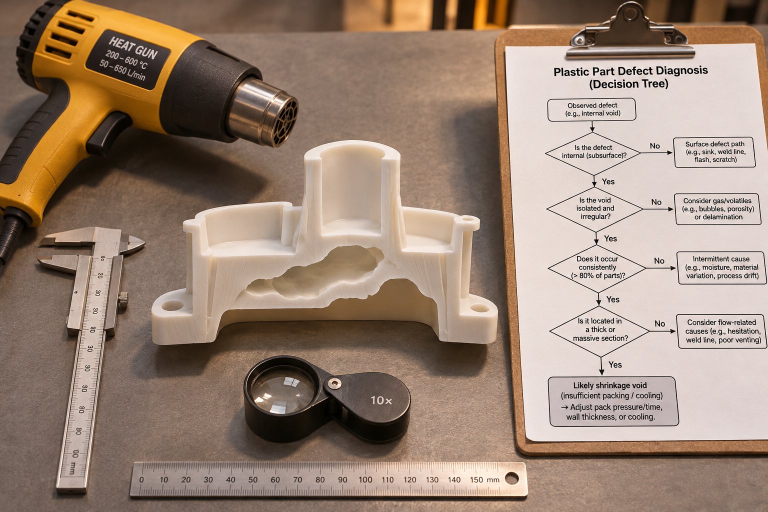
A Systematic Troubleshooting Framework for Void Defects
Material science, process optimization, mold design, plasticizing hardware — each of the previous sections hands you a piece of the puzzle. But pieces without a sequence are just clutter. On the production floor, what separates an experienced process engineer from a frustrated operator isn't the number of fixes they know — it's the order in which they apply them. Most troubleshooting guides hand you a flat, unstructured list: "try higher pack pressure, try better venting, try more drying." That shotgun approach leads to changing three variables at once, confusing cause and effect, and burning shifts chasing ghosts.
A better model is the decision tree — a branching, sequential method that mirrors how a seasoned engineer actually thinks when voids in injection molded parts refuse to go away. Each step narrows the field before you touch a single dial. Here's the framework, broken into three disciplined phases.
Step One — Identify and Classify the Void Type
This single step prevents the most expensive mistake in the entire troubleshooting process: applying gas-void corrections to a vacuum-void problem, or the reverse. Before adjusting any parameter, answer one question — what are vacuum voids in injection molding versus gas voids, and which one am I looking at right now?
Start with physical evidence:
- Cross-section the part through the suspected void area. Use a band saw for a quick cut or a microtome for cleaner inspection surfaces.
- Examine the void's interior under magnification (even a 10x loupe works). Smooth, clean, glossy walls point to a vacuum void. Rough, discolored, sooty, or irregular walls point to a gas void.
- Note the void's location relative to wall geometry. Centered in the thickest cross-section? Classic vacuum void. Clustered near a blind rib, weld line, or last-to-fill zone? Likely trapped air. Scattered irregularly along the flow path? Suspect moisture or degradation volatiles.
- Perform the heat-gun diagnostic described earlier in this article. Warm the surface directly above the void until the skin softens, then observe:
- Surface sinks inward → negative internal pressure → vacuum void.
- Surface blisters outward → positive internal pressure → gas void.
Record your classification. If you're working with a hygroscopic resin — polycarbonate, nylon, PET — test multiple locations, because both void types can coexist in the same part. Only after classification is confirmed should you move to step two.
Step Two — Isolate the Root Cause Category
Classification tells you which branch of the decision tree to follow. Each branch has its own priority sequence, ordered from the most common and most correctable cause to the least accessible one. Work through the sequence in order — don't skip ahead.
If the void is a gas void:
- Check material moisture content first. Pull a resin sample from the hopper throat and test it with a moisture analyzer. If the reading exceeds the resin manufacturer's specification, the drying system is the root cause. Verify dryer function: dew-point temperature, airflow, hopper residence time, and desiccant condition. This single check resolves a disproportionate share of gas-void cases.
- If moisture is within spec, move to the next check.
- Evaluate barrel temperatures for degradation. Review actual barrel zone temperatures against the resin's recommended processing window. Look for zones running above the upper limit, excessive residence time from an oversized barrel or slow cycle, and any signs of material discoloration in purge shots. Thermal degradation volatiles produce gas voids that drying alone cannot fix.
- If temperatures are appropriate and purge shots look clean, move to the next check.
- Inspect mold venting for trapped air. Examine vent channels at every last-to-fill location, blind rib tip, and deep boss. Look for residue buildup, crushed vents, or areas that were never vented in the original tool design. As research into in-cavity pressure monitoring demonstrates, trapped air from an insufficient venting system creates measurable pressure anomalies at the end of fill — anomalies that correlate directly with burn marks, short shots, and internal gas pockets.
- If venting is clean and adequate, investigate back pressure settings, decompression (suck-back), and compound-level volatile content (regrind percentage, additive packages).
If the void is a vacuum void:
- Evaluate part design for excessive wall thickness. Measure the actual wall in the void zone. If the section is significantly thicker than the nominal wall — a thick boss, a heavy rib-wall junction, or a solid pad — no process adjustment may be able to pack the core before gate seal. Design modification (coring, rib redesign, gas assist) belongs on the corrective action list before extensive process experimentation.
- If wall thickness is within a packable range, move to the next check.
- Audit packing parameters — pressure, time, and gate seal. Run a gate-seal study to confirm whether pack time is long enough for the gate to fully freeze while pressure is still active. Verify that pack pressure is set high enough to transmit through the cooling melt to the void area. Check gate size — a gate that freezes prematurely cuts off packing before the core is compensated.
- If gate seal and pack pressure are confirmed adequate, move to the next check.
- Assess cooling uniformity. Look for hot spots — areas far from cooling lines, poorly cooled core pins, or circuits with restricted flow. Differential cooling creates localized shrinkage that packing cannot overcome. Thermal imaging of the mold surface or review of coolant flow rates across circuits can reveal imbalances.
- If cooling is uniform and packing is optimized, inspect plasticizing hardware (check-ring seal, screw-flight condition, barrel bore) for pressure-transmission losses — the masking effect discussed in the hardware section.
The fastest way to reduce voids in injection molding is not to try every fix at once — it is to classify the void, follow the correct branch, and eliminate causes in priority order.
Step Three — Apply Targeted Corrections and Verify
Diagnosis without disciplined execution just creates a different kind of guessing. Once you've identified the most probable root cause from step two, the correction phase follows three rules that separate systematic problem-solving from trial-and-error noise.
Rule 1: Change one variable at a time. This sounds elementary, and it is — yet it's violated constantly under production pressure. When you adjust pack pressure, melt temperature, and vent depth in the same session, and the voids improve, you don't know which change mattered. Worse, you may have introduced a new issue masked by the improvement. Isolate. Adjust. Verify. Then move to the next variable only if needed.
Rule 2: Verify with physical evidence, not assumptions. After each adjustment, cross-section fresh sample parts and examine the void area. Measure void size, location, and frequency. Are the voids smaller? Fewer? Shifted in position? Gone entirely? Visual inspection of the part exterior is not sufficient — remember, the defining characteristic of this voids defect in injection molding is that it hides beneath an apparently perfect surface. Only internal evidence confirms whether the correction worked.
Rule 3: Use cavity-pressure monitoring when available. If your mold is equipped with in-cavity pressure sensors, the pressure profile provides a real-time window into whether your packing adjustments are actually reaching the problem area. A study on cavity pressure profiling demonstrated that comparing measured in-cavity pressure curves to a known adequate profile enabled engineers to systematically identify which process conditions were incorrectly set — and then iteratively correct them until the profile matched the target. Cavity pressure doesn't just tell you what's happening at the machine nozzle; it tells you what's happening at the part. That distinction is critical when troubleshooting voids, because pressure losses between the nozzle and the cavity — from a frozen gate, a worn check ring, or an undersized runner — are invisible on the machine controller but plainly visible on a cavity-pressure trace.
What happens when you've worked through the decision tree, applied corrections methodically, and voids still haven't disappeared? That plateau is a signal — not a failure. It means the root cause lives in a layer you haven't reached yet. If process adjustments plateau on a gas void, the issue may be in compound formulation, additive volatility, or barrel sizing. If process adjustments plateau on a vacuum void, the issue is almost certainly in tooling design (wall thickness, gate location, cooling layout) or hardware condition (check-ring seal, barrel wear). The decision tree doesn't end — it redirects you back to the appropriate earlier section of this framework with sharper focus.
Systematic troubleshooting transforms how to reduce voids in injection molding from a frustrating guessing game into a repeatable engineering discipline. Classify first. Follow the correct branch. Change one thing at a time. Verify with cross-sections. And when you hit a ceiling, let the evidence — not intuition — tell you where to look next. That discipline raises a final, pragmatic question: once you've reduced voids as far as process and tooling allow, how do you decide whether the remaining ones actually matter?
Void Acceptability and a Lifecycle Approach to Prevention
Here's a question that almost never gets asked in troubleshooting guides: does this void actually matter? The previous sections walked you through classifying, diagnosing, and correcting internal cavities — but the implicit assumption throughout was that every void demands elimination. In practice, that assumption isn't always true. A small vacuum void buried in a non-structural rib of a hidden housing panel is a fundamentally different problem than the same void sitting at the root of a snap-fit beam in a safety-critical automotive connector. Treating both with equal urgency wastes engineering time, machine hours, and production capacity on defects that may never affect part function.
The pragmatic reality of production is this: zero voids is an ideal, not always an economically justified target. Knowing where to draw the line — and how to verify you're on the right side of it — is the final skill in a complete void-prevention strategy.
When Voids Are Cosmetically Acceptable vs Structurally Critical
Void acceptance criteria in injection molding are rarely universal. They're defined by the intersection of three factors: what the part does, where the void sits, and what the customer's specification requires. A molded decorative cover assembled inside an appliance faces a completely different performance threshold than a pressurized fuel-system connector or a load-bearing medical device housing.
In non-structural, non-visible applications, small internal voids within defined size and frequency limits may be perfectly acceptable. Many customer specifications set void acceptance criteria injection molding based on measurable thresholds — void diameter as a percentage of local wall thickness, maximum number of voids per part, or maximum cumulative void volume within a defined region. As one industry classification framework emphasizes, process engineers should sort defects into categories — cosmetic-only, cosmetic-visible, structural, and critical-to-quality — before deciding on the response level. A vacuum void in a non-load-bearing cosmetic rib might warrant monitoring rather than elimination, while an identical void at the root of a snap-fit beam demands immediate corrective action.
Several factors escalate a void from tolerable to critical. If any of these apply to your part, the threshold for acceptable void size and frequency drops sharply:
- Load-bearing applications: Voids act as internal stress concentrators. Under tensile, compressive, or bending loads, the material surrounding the cavity bears disproportionate stress, reducing effective strength and accelerating crack initiation.
- Pressure-containing parts: Any internal cavity in a part designed to hold fluid or gas pressure creates a potential leak path or rupture initiation site — especially if the void sits near a sealing surface or wall minimum.
- Transparent or translucent materials: In clear polycarbonate, PMMA, or other optical-grade resins, even a small void is visible to the naked eye. What might be structurally harmless becomes a cosmetic reject in applications where optical clarity is a requirement.
- Fatigue-loaded components: Parts subjected to cyclic loading — hinges, living springs, vibration-exposed brackets — are especially sensitive to internal discontinuities. A void that causes no issue under static load can become a fatigue crack origin under repeated stress cycles, dramatically shortening part life.
- Safety-critical automotive or medical parts: Components governed by PPAP-level quality requirements (typically Cpk of 1.33 or higher), FMEA-driven risk assessments, or regulatory submissions carry near-zero tolerance for uncharacterized internal defects. In these applications, void acceptance criteria are often defined explicitly in the engineering drawing or customer specification, and any deviation requires formal disposition.
When specifications don't explicitly define void limits — and many don't — the engineering team must make a judgment call based on the part's function, failure mode, and safety implications. The conservative approach: if you can't demonstrate that the void won't affect performance, treat it as unacceptable until evidence says otherwise.
Inspection Methods for Detecting Internal Voids
You can't make an accept-or-reject decision on a defect you haven't measured. How to detect voids in injection molded parts depends on the precision you need, the volume of parts you're inspecting, and whether you can afford to destroy the sample.
Destructive methods are the simplest and most accessible:
- Cross-sectioning: Cut the part through the suspected void region with a band saw or precision cutting tool. Examine the exposed surface visually or under magnification. This method is fast, inexpensive, and gives you direct access to the void's shape, size, and interior surface characteristics. The limitation? You've destroyed the part, you can only examine the single plane you cut through, and you may miss voids located elsewhere in the geometry.
- Microtoming: For higher-precision examination, thin slices can be taken through the void area and examined under optical or electron microscopy. This provides detailed information about void morphology and the polymer structure surrounding the cavity, but it's time-consuming and limited to laboratory settings.
Non-destructive methods preserve the part and provide volumetric data:
- Industrial CT scanning: X-ray computed tomography reconstructs a full three-dimensional model of the part's internal structure from hundreds of radiographic projections. As Nel PreTech's CT inspection guidance explains, CT can locate and characterize encapsulated voids — including their number, size, volume, distribution, and position relative to critical features — all without altering the specimen. The same dataset can support wall-thickness analysis, CAD comparison, and dimensional inspection. For void acceptance decisions, CT provides the most complete evidence base: you see every void in the part, not just the ones that happen to intersect a cut plane. The key consideration is resolution — CT resolution should be approximately one-third of the minimum defect size you need to analyze quantitatively.
- Ultrasonic testing: Sound waves transmitted through the part reflect off internal discontinuities, indicating the presence and approximate location of voids. Ultrasonic methods are faster and less expensive than CT for simple geometries, but their effectiveness depends on material type, part geometry, surface access, and defect orientation. Complex molded parts with ribs, bosses, and variable wall thickness can be difficult to inspect ultrasonically with confidence.
Choosing between these methods depends on the engineering question. For a quick process-development check during a mold trial, cross-sectioning a handful of parts at the thickest section gives you actionable information in minutes. For qualifying a production process, comparing good versus bad parts across cavities, or documenting void conditions for a customer PPAP submission, industrial CT scanning delivers the depth and traceability that destructive methods cannot match. As the Nel PreTech team puts it: visualizing a feature is different from analyzing it quantitatively — and the inspection method must be designed around the engineering requirement, not around convenience.
Bridging Prevention and Practical Production Reality
Void prevention isn't a single fix. It's a lifecycle discipline that spans every phase from material selection to final quality verification. Each link in the chain addresses a different mechanism, and skipping any one of them leaves a gap that downstream corrections may not be able to close.
Here's the complete prevention lifecycle, assembled from every layer this article has covered:
- Material selection and preparation: Choose resins with shrinkage characteristics appropriate for the part geometry. Dry hygroscopic materials to verified moisture specifications using desiccant dryers and moisture analyzers — not timer-based assumptions. Evaluate volatile content in additive packages and regrind blends.
- Part and mold design: Maintain uniform wall thickness wherever possible. Core out thick sections. Size and locate gates to maximize packing reach into the thickest areas. Place cooling channels for uniform heat extraction, using conformal cooling where straight-drilled lines can't reach. Vent every last-to-fill zone, blind rib, and deep boss.
- Plasticizing hardware specification: Ensure the screw geometry — compression ratio, flight depth, mixing elements, and L/D ratio — matches the resin's melting and mixing demands. Verify that barrel capacity is appropriately sized to the shot volume to avoid excessive residence time. Inspect the check ring, screw flights, and barrel bore for wear that could undermine pressure transmission or melt consistency. For molders evaluating whether their plasticizing components are correctly matched to the application, NANHAIYA's custom injection molding screw barrels offer a tailored replacement path that considers screw geometry, wear history, and resin-specific requirements — one link in this chain, but a link that determines whether your optimized process settings actually reach the cavity.
- Process optimization: Set packing pressure and hold time based on a gate-seal study, not guesswork. Calibrate melt and mold temperatures to balance packing effectiveness against degradation risk. Optimize injection speed for a smooth, continuous flow front. Set back pressure high enough to expel entrapped air during screw recovery.
- Quality inspection and verification: Cross-section sample parts during process development to confirm void elimination. Use CT scanning or ultrasonic testing for production qualification and ongoing monitoring. Define void acceptance criteria based on the part's functional requirements, not a blanket zero-defect assumption. Compare parts across cavities, material lots, and process changes to catch drift before it becomes a systemic problem.
Each step builds on the one before it. Material preparation removes gas sources. Mold design creates the thermal and geometric conditions for effective packing. Properly specified hardware ensures the machine can deliver what the process demands. Process optimization fine-tunes the balance. And inspection closes the loop, verifying that the chain held — or identifying exactly where it didn't.
Voids in injection molding are among the most deceptive defects a molder can face — invisible from the outside, mechanistically complex, and stubbornly resistant to unstructured troubleshooting. The systematic approach outlined across this article replaces guesswork with diagnosis: classify the void type before touching a setting, follow the correct branch of the decision tree, change one variable at a time, and verify with physical evidence. Whether the root cause turns out to be moisture in the resin, insufficient packing through a frozen gate, a hot spot from a missing cooling line, or a leaking check ring that silently bleeds away your pack pressure, the method is the same. Identify. Isolate. Correct. Verify. That discipline — not any single parameter adjustment — is what turns chronic void problems into solved ones.
Frequently Asked Questions About Voids in Injection Molding
1. What causes voids in injection molding?
Voids form through two distinct mechanisms. Vacuum voids occur when the outer skin of a part solidifies before the molten core finishes shrinking, creating internal tensile stress that pulls the polymer apart and leaves a cavity under negative pressure. Gas voids result from trapped air due to poor mold venting, flash-vaporized moisture from insufficiently dried hygroscopic resins like nylon or polycarbonate, or volatile off-gassing from thermal degradation or additives. Semi-crystalline resins with high volumetric shrinkage and thick-walled part geometries are especially prone to vacuum voids, while gas voids tend to appear in last-to-fill zones, near weld lines, or scattered along the flow path when moisture is the source.
2. How do you tell the difference between a vacuum void and a gas void?
Two practical methods help classify the void type. First, cross-section the part through the defect area and examine the cavity walls under magnification: smooth, clean, glossy interior walls indicate a vacuum void caused by shrinkage, while rough, discolored, or sooty walls suggest a gas void from trapped air, moisture, or degradation. Second, use the heat-gun diagnostic test - gently warm the surface above the void until the skin softens. If the surface draws inward (sinks), the cavity is under negative pressure, confirming a vacuum void. If the surface blisters outward, internal gas pressure is present, confirming a gas void. This classification step is critical because the corrective actions for each type are nearly opposite.
3. How do you prevent voids in thick-walled injection molded parts?
Thick walls are the primary driver of vacuum voids because the freeze front cannot reach the core before the gate seals, leaving a large volume of material to shrink without pressure compensation. Prevention strategies include coring out thick sections to reduce thermal mass, redesigning solid sections into thinner ribbed structures (ribs at 40-60% of adjoining wall thickness), using gas-assist molding to hollow out cores, and tapering wall transitions gradually rather than stepping them abruptly. On the process side, increasing packing pressure, extending hold time up to gate seal, enlarging the gate to delay freeze-off, and raising mold temperature to slow skin formation all extend the effective packing window into the thick core region.
4. Can worn screws and barrels cause voids in injection molding?
Yes, worn plasticizing hardware is a frequently overlooked cause of persistent voids. A worn check ring (non-return valve) allows melt to leak backward during the packing phase, meaning the pack pressure displayed on the controller never fully reaches the cavity - creating vacuum voids despite seemingly adequate settings. Worn screw flights reduce compression and melting efficiency, leaving unmelted regions that trap air and cause gas voids. An oversized barrel relative to shot size extends residence time, risking thermal degradation and volatile off-gassing. Companies like NANHAIYA offer custom injection molding screw barrels engineered to match specific resin and application requirements, addressing root-cause hardware mismatches rather than simply replacing worn parts with identical geometry.
5. Are all voids in injection molded parts unacceptable defects?
Not necessarily. Void acceptability depends on the part's function, the void's location, and customer specifications. In non-structural, non-visible applications, small internal voids within defined size and frequency limits may be perfectly tolerable. However, voids become critical in load-bearing parts (stress concentration risk), pressure-containing components (leak or rupture risk), transparent materials (visible cosmetic defect), fatigue-loaded parts (crack initiation under cyclic stress), and safety-critical automotive or medical components. Inspection methods range from simple cross-sectioning for quick process checks to industrial CT scanning for full volumetric characterization during production qualification. The key is defining acceptance criteria based on engineering requirements before deciding whether to invest in further elimination efforts.
Written by
Nanhaiya Technical Team
Zhoushan Nanhaiya Plastic Machinery Co., Ltd.
The Nanhaiya technical team supports screw and barrel manufacturing projects through application review, technical communication, custom manufacturing coordination, and production and quality control.
Discuss Your Application
Related Articles
More insights on screw barrel technology and plastics processing.

Injection Molding Color Mixing: From Streaks to Flawless Consistency
Nov 19, 2026
Master injection molding color mixing with expert guidance on colorant types, screw design, process parameters, defect troubleshooting, and Delta E QC protocols.
Read Article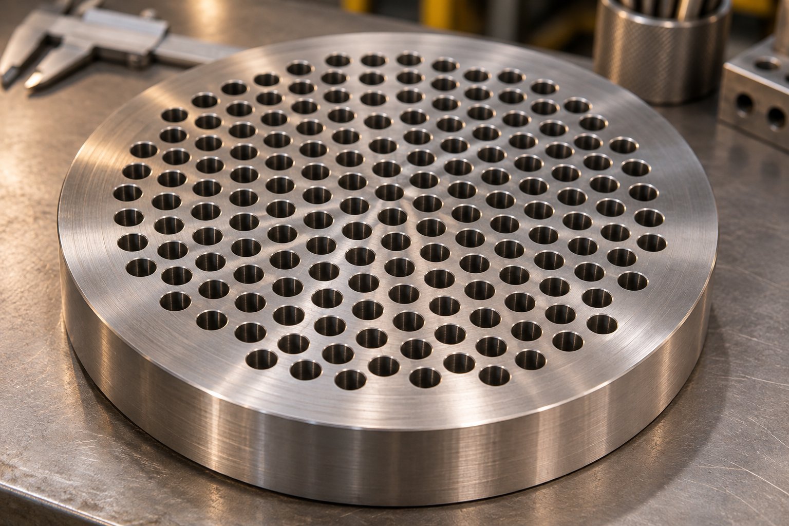
Wrong Extruder Breaker Plate? Spot the Signs Before Scrap Piles Up
Nov 19, 2026
Learn how to select, size, and maintain your extruder breaker plate. Covers hole geometry, pressure drop, polymer-specific specs, and troubleshooting tips.
Read Article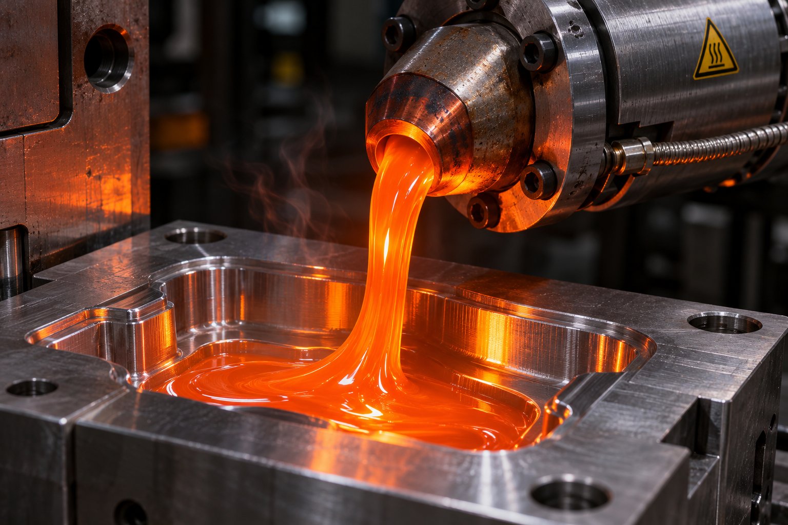
Injection Molding Melt Temperature: Why Your Barrel Settings Lie
Nov 19, 2026
Learn why barrel set points lie about injection molding melt temperature. Complete resin chart, measurement methods, defect troubleshooting, and optimization steps.
Read ArticleLooking for something else?
Search by material, symptom or product and jump straight to the relevant page.
These are navigation suggestions based on keyword matching — not a quotation, not a delivery commitment, and not a substitute for engineering review. Final specification is confirmed by our engineers against your drawings and processed material.
Need help with screw barrel selection?
Share your machine model, processed material and application. Our team can help with pricing and technical support.