

What Weld Lines Are and Why They Matter
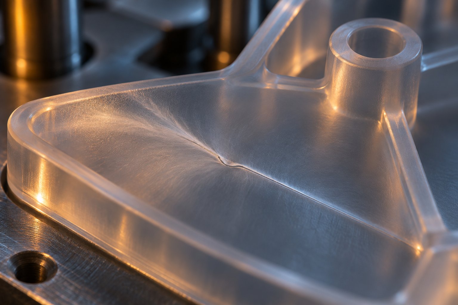
Imagine you're inspecting a freshly molded plastic part. The surface looks clean, the dimensions check out, and the color is uniform. Yet hidden within the wall thickness sits a flaw capable of slashing the part's mechanical strength by anywhere from 20% to over 70%. That flaw is a weld line, and it forms during every molding cycle where the melt flow splits and reconverges.
Defining Weld Lines in Injection Molding
A weld line is a linear mark, and more importantly a structural boundary, that appears wherever two or more molten polymer flow fronts meet inside a mold cavity and fail to fully re-entangle at the molecular level. The polymer chains on each side of this boundary merely press against one another rather than interdiffusing to recreate the bulk material's chain network. The result is a region of incomplete polymer chain entanglement that behaves like a built-in micro-crack under load.
A weld line is a visible mark and mechanical weak zone formed where two or more melt flow fronts converge during injection molding and fail to fully bond at the molecular level, creating both a cosmetic defect and a stress-concentration site in the finished part.
Every part geometry that forces the melt stream to divide, flow around an obstacle, and rejoin will produce at least one weld line. Think about core pins that create holes, bosses rising from the cavity floor, ribs splitting the flow path, or multi-gate filling strategies that launch separate flow fronts from different entry points. In each scenario, the split fronts eventually collide, and the quality of their reunion determines whether the resulting weldline in injection moulding is a minor cosmetic blemish or a genuine structural liability.
This makes the defect fundamentally different from a random process upset. A weld line isn't something that appears on a bad day; it's baked into the part design and mold layout from the start.
Why Weld Lines Demand Attention
The stakes are both visual and mechanical. On the cosmetic side, a visible weld line on a Class-A surface can trigger part rejection in automotive interiors, consumer electronics housings, and medical device enclosures. On the structural side, the consequences can be far more serious.
Strength retention at a weld line varies dramatically by material. Unfilled semi-crystalline polymers like PP can retain upward of 80-95% of their base tensile strength, while glass-fiber-reinforced grades such as PA66-GF30 may drop to just 50-60% of the unwelded value. Impact strength losses are even steeper. The reason? Fibers at the weld plane align parallel to the interface instead of bridging across it, stripping away the reinforcement the part was designed around.
These numbers explain why weld lines are sometimes called the number-one hidden structural defect in molded parts. They can pass a quick visual check at the surface while quietly undermining load-bearing capacity through the entire wall section. Rejected cosmetic parts inflate scrap rates; undetected weak weld zones risk in-service failures, warranty claims, and safety incidents.
So how do you identify, predict, and control a defect that's inherent to the process itself? The answer spans terminology, polymer science, material selection, part geometry, process parameters, plasticizing hardware, advanced molding technologies, and filling simulation. Each layer of understanding compounds the last, and a gap in any one area leaves performance on the table.
The logical starting point is language. The industry uses the terms "weld line," "knit line," and "meld line" loosely, yet they describe meaningfully different phenomena with different strength implications. Sorting out that terminology is the first step toward making smarter design and process decisions.
Weld Lines vs Knit Lines vs Meld Lines
Most technical resources treat "weld line" as a catch-all label for any mark left where flow fronts converge. That shorthand hides a distinction that directly affects part strength, cosmetic severity, and the corrective actions available to you. Three separate terms exist for a reason, and understanding the difference between them gives mold designers and process engineers a sharper lens for diagnosing problems and choosing solutions.
Weld Lines vs Knit Lines Explained
The dividing line between these defect types comes down to a single measurable quantity: the angle at which the two melt fronts meet, often called the flow angle or convergence angle.
When two flow fronts collide nearly head-on, at an included angle below roughly 135 degrees, they have almost no opportunity to continue flowing together after contact. The chains on each front press flat against one another and freeze in place. This is a weld line in the strict sense, sometimes called a stagnant weld. Because neither front moves appreciably after convergence, packing pressure has limited ability to push material across the interface. The molecular entanglement stays poor, and the resulting seam is both the most visible and the weakest of the three types.
A knit line, sometimes called a meld line, forms when the same split-and-rejoin event happens at a wider convergence angle, generally above 135 degrees. Picture the melt splitting around a core pin and reconverging on the downstream side, then continuing to flow together toward the end of the cavity. Because the fronts merge at a shallow angle and keep advancing in roughly the same direction, there is more time and mechanical action for polymer chains to interdiffuse across the interface. Research on flow-angle thresholds indicates that once the convergence angle reaches approximately 140 to 150 degrees, the seam's influence on strength effectively vanishes, a point sometimes referred to as the weld line vanishing angle.
The following table puts all three terms side by side so you can compare them at a glance:
| Term | Meeting Angle | Flow After Convergence | Relative Strength | Cosmetic Severity |
|---|---|---|---|---|
| Weld Line (stagnant weld) | Below ~135°, often near 0° (head-on) | Minimal or none; fronts stagnate at the interface | Lowest; limited molecular interdiffusion | Most visible; sharp V-notch, possible discoloration |
| Knit Line | Above ~135° but below the vanishing angle (~140–150°) | Moderate continued flow in a similar direction | Moderate; improved chain entanglement from continued flow | Moderate; softer surface mark, less pronounced notch |
| Meld Line | Near or above the vanishing angle (~140–150°+) | Significant continued flow; fronts travel together | Highest; approaches base-material strength | Mild to negligible; often only visible under specific lighting |
You'll notice the terms "knit line" and "meld line" are sometimes used interchangeably in shop-floor conversation. Technically, a meld line sits at the gentlest end of the spectrum, where the angle is wide enough that strength loss is negligible. For practical purposes, the critical boundary to remember is the 135-degree threshold: below it, you're dealing with a true weld line and all the structural risk that implies.
Practical Implications of the Distinction
Why does this angular detail matter when you're standing at a molding press or reviewing a mold design? Because it turns a seemingly fixed defect into something you can influence.
If a fill analysis or a molded part reveals a stagnant weld line sitting right on a load-bearing boss, the goal isn't necessarily to eliminate the convergence zone entirely. That may be geometrically impossible. Instead, a mold designer can reposition the gate, add a flow leader, or adjust wall thickness locally so the two fronts meet at a wider angle, converting that weld line into a knit line or even a meld line. The convergence still happens, but it happens under conditions that allow more chain entanglement and easier pressurization of the interface.
Think of it like a highway merge. Two lanes meeting head-on create a collision. The same two lanes merging at a gentle angle, with traffic continuing in the same direction, blend smoothly. RJG draws a similar analogy, comparing a meld line to merging onto a freeway, where everyone is heading the same way, versus a knit line to a head-on collision at a four-way stop.
This distinction also affects how you read injection moulding flow lines in simulation software. Most fill-analysis tools report both the location of convergence zones and the local flow angle at each point. Armed with the 135-degree criterion, you can quickly sort the results into high-risk weld lines and lower-risk knit or meld lines, then focus your design iterations where they matter most.
Throughout the rest of this article, the term "weld line" will be used in its precise sense, referring to head-on or near-head-on convergence, whenever the distinction is structurally relevant. Where the broader phenomenon is under discussion, that will be made clear. Getting the vocabulary right is the first step; the next is understanding the physics that make these interfaces weak in the first place, starting with how the melt front actually behaves at the moment of convergence.
Fountain Flow Mechanics and the V-Notch Effect
Knowing that a weld line forms where fronts converge, and that the convergence angle governs severity, still leaves a deeper question unanswered: what is actually happening inside the melt at the instant those fronts touch? The answer lives in a phenomenon called fountain flow, and it explains why even a cosmetically subtle weld line can behave like a built-in crack under mechanical load.
Fountain Flow and Melt Front Behavior
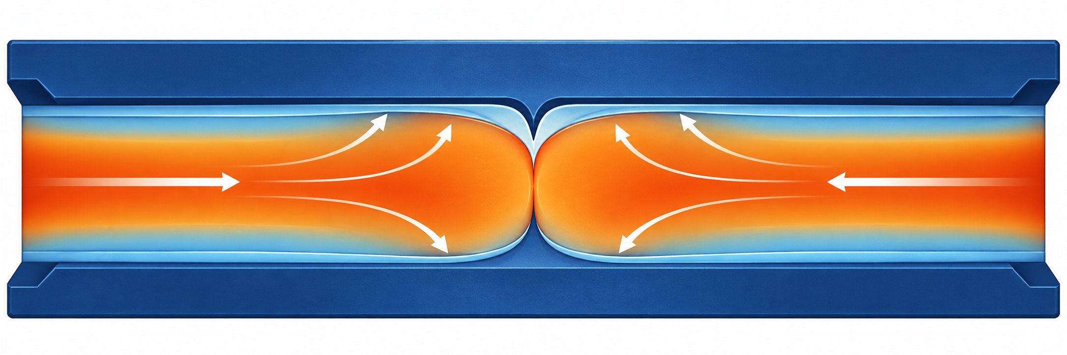
Imagine watching a cross-section of molten polymer as it advances through the mold cavity. The material doesn't slide forward like a solid piston. Instead, the hottest, fastest-moving melt at the center of the flow channel pushes ahead, then rolls outward toward the cooler mold walls, much like water rolling over the lip of a fountain. As each layer of melt touches the relatively cold steel, it freezes almost instantly, forming a thin skin. Fresh material from behind flows over this frozen layer, reaches the advancing front, rolls outward, and freezes in turn. The skin grows thicker the farther you move from the gate, while the still-molten core channel narrows progressively.
This "inside-out" behavior has a critical consequence for weld lines. By the time two advancing fronts meet, each one presents its outermost layer to the other, and that outermost layer is the coldest, most oriented, and least mobile material in the entire flow cross-section. The polymer chains in these skin layers have already stretched and partially solidified in the direction of flow. When the two skins press together, there is very little thermal energy or molecular mobility left to drive chain diffusion across the interface.
Think of it this way: you're trying to weld two pieces of plastic together, but the surfaces you need to bond are the coldest parts of the entire melt pool. The hot, mobile core material that could easily interdiffuse is trapped behind frozen walls on both sides.
Several factors compound this problem at the convergence zone. Here are the key contributors that degrade bonding at the weld interface:
- Frozen skin layer thickness: The thicker the solidified skin at the melt front, the less molten material is available to flow across the interface. Parts with long flow lengths or low mold temperatures develop thicker skins before convergence, producing weaker weld lines.
- Reduced molecular mobility at the front: Fountain flow continuously deposits the coolest melt onto the advancing tip. Polymer chains at this leading edge have lower thermal energy and shorter relaxation times, limiting their ability to reptate (snake) across the boundary into the opposing front.
- Trapped air and volatiles: When two fronts converge, any air ahead of them, along with moisture vapor or degradation gases, can become trapped at the interface. These pockets act as voids that interrupt chain contact and reduce the effective bonding area.
- Chain orientation parallel to the weld plane: The fountain-flow rolling action orients polymer molecules along the flow direction, which at a head-on weld line means the chains lie parallel to the interface rather than bridging across it. Research on fiber-reinforced thermoplastics confirms this effect is especially severe for fillers: glass fibers at the weld plane align perpendicular to the loading direction, stripping away reinforcement exactly where it is needed most.
Each of these factors alone would weaken the interface. Acting together, they create a boundary zone where molecular entanglement can be a fraction of what exists in the bulk material just millimeters away.
The V-Notch Stress Concentration Mechanism
Poor molecular bonding across the interface is only half the story. The other half is geometry, and it's the part that most discussions of welding lines overlook entirely.
When two fountain-flow fronts press together, the frozen skins on each side don't merge into a perfectly flat plane. Instead, the slight curvature of each melt front and the thin layer of trapped air or poorly bonded material create a tiny V-shaped notch on the part surface. Sometimes you can see it as a faint line; sometimes it's almost invisible to the naked eye. Either way, the notch is there, and it has mechanical consequences far out of proportion to its size.
Any sharp geometric discontinuity on or within a loaded part concentrates stress at its tip. Engineers call this a stress riser or stress concentrator, and it follows the same principle that makes a small nick in a piece of glass cause it to shatter along that line. The V-notch at a weld line acts as a pre-existing crack initiation site. Under tensile or bending loads, the local stress at the notch root can be several times higher than the nominal stress in the surrounding wall.
Here's where weld lines become disproportionately dangerous: the V-notch sits precisely on the plane of weakest molecular bonding. You have a geometric stress multiplier stacked directly on top of a material-level weakness. The notch drives stress concentration toward the interface, and the interface lacks the chain entanglement to resist crack propagation. The two mechanisms feed each other, and the result is a failure path that activates at loads well below what the base material could handle.
This dual mechanism, poor interdiffusion plus geometric stress concentration, is why knit lines with wider convergence angles perform so much better. A gentler merge angle produces a shallower, less defined surface notch and allows more chain entanglement across the boundary, attacking both failure drivers simultaneously.
For part designers, the practical takeaway is straightforward but often underappreciated: evaluating whether a weld line is acceptable in a load-bearing region requires more than checking the material's nominal strength. You need to account for the localized stress state at the notch and the reduced bonding across the interface. A weld line sitting in a low-stress, non-cosmetic zone may be perfectly harmless. The same weld line relocated to a snap-fit latch or a pressurized boss could become the dominant failure mode.
Understanding fountain flow and the V-notch effect reveals that the root causes of weak weld lines are thermal and geometric in nature. That insight points directly to the next variable in the equation: the polymer itself. Different resin families solidify at different rates, crystallize in different patterns, and respond to fillers in dramatically different ways, all of which shift the severity of weld-line defects from one material to the next.
How Different Polymers Respond to Weld Line Formation
Fountain flow and the V-notch mechanism explain why weld lines are weak, but they don't explain why the same defect can be nearly invisible in one resin and catastrophic in another. A weld line in unfilled polypropylene might retain almost all of the base material's tensile strength, while the same convergence zone in a 30% glass-fiber-reinforced nylon can lose more than half. The difference comes down to how each polymer family solidifies, how its chains move during the brief bonding window, and whether fillers or fibers are present to disrupt the interface further.
Despite the enormous practical importance of this variation, most discussions of weld lines in injection molding treat all plastics as though they behave alike. They don't. A systematic look at polymer classes and their weld-line sensitivity gives part designers and process engineers a far more realistic starting point for material selection and risk assessment.
Amorphous vs Semi-Crystalline Polymers at the Weld Interface
The single most important material-level variable governing weld-line strength is how much molecular interdiffusion occurs across the interface before the polymer solidifies. Two measurable properties dominate that diffusion window: viscosity (a proxy for chain mobility) and the temperature gap between processing temperature and glass-transition temperature (which dictates how long the chains remain mobile after the fronts touch).
Here's where the two major polymer families diverge sharply.
Semi-crystalline unreinforced resins such as PA (nylon), PP, PE, and POM consistently exhibit high weld-line strength retention. A statistical analysis of published weld-line data by PART Engineering found a median weld-line factor of 0.96 for semi-crystalline unreinforced plastics, meaning these materials retain roughly 96% of their bulk tensile strength at the weld. In several cases, the weld line healed so completely that it was not even morphologically recognizable under microscopy, aside from the structural V-notch on the surface. The crystallites had grown homogeneously across the former contact zone.
Why such strong healing? Semi-crystalline resins typically process at temperatures far above their glass-transition temperature, creating a wide diffusion window. Their melt viscosities also tend to be relatively low compared to many amorphous plastics. Both factors favor rapid chain entanglement across the interface before the material locks into its crystalline structure.
Amorphous unreinforced resins such as ABS, PMMA, PS, and most grades of PC tell a different story. The same PART Engineering study reported a median weld-line factor of just 0.55 for this class, meaning roughly 45% of the bulk strength is lost at the weld. The processing-to-Tg temperature gap is typically much narrower for amorphous polymers, so the chains have less time to interdiffuse before mobility freezes out. Their viscosities also tend to run higher, further restricting molecular movement at the interface.
There is, however, a notable exception: polycarbonate. Despite being amorphous, PC has an unusually low melt viscosity compared to other amorphous engineering resins. That easy flow gives its chains enough mobility to achieve interdiffusion levels closer to those of semi-crystalline materials. The PART Engineering data showed PC as a clear outlier among amorphous plastics, with weld-line strength approaching semi-crystalline territory. The takeaway? Viscosity matters at least as much as crystal structure when predicting weld-line performance.
For both polymer families, raising the mold temperature widens the diffusion window by slowing the rate at which the melt-front skin solidifies. This lever is especially critical for semi-crystalline materials, where crystallization kinetics at the cooled interface can slam the bonding window shut. A hotter mold surface delays crystallization onset, giving chains more time to snake across the boundary. Experimental work on PA6 + 30% fiberglass composites demonstrated that increasing mold temperature from room temperature to 153-173 degrees Celsius dramatically improved elongation at the weld line, from roughly 4.6% to over 12%, confirming the power of thermal management at the interface.
Fiber-Reinforced and Filled Materials
If unfilled semi-crystalline resins sit at the favorable end of the weld-line spectrum, glass-fiber-reinforced and mineral-filled compounds occupy the opposite extreme. This is where injection molding weld lines become a serious structural concern rather than a manageable nuisance.
Recall the fountain-flow mechanism from the previous section: at the melt front, material rolls outward toward the mold walls, stretching and orienting whatever is suspended in the matrix. For unfilled polymers, this means chain orientation parallel to the weld plane. For fiber-reinforced grades, it means fibers orient parallel to the weld plane as well, perpendicular to any tensile load applied across the interface. This is the worst possible alignment for load transfer.
Imagine trying to pull two halves of a part apart at the weld. In the bulk material away from the weld, fibers bridge the cross-section and carry a large share of the load. At the weld interface, those same fibers lie flat along the boundary, contributing nothing to cross-interface reinforcement. Worse, the fibers physically occupy space in the interface plane, reducing the area of matrix-to-matrix contact where molecular diffusion could otherwise occur. The reinforcement that justifies using a filled grade in the first place effectively disappears at the weld.
Research on glass-fiber-reinforced polypropylene composites illustrates this vividly. For PP-20GF, the weld-line factor for tensile strength hovered between 0.53 and 0.55 across a range of injection temperatures, meaning nearly half the tensile strength vanished at the weld. At 30 wt% glass fiber, the degradation became even more severe: the tensile weld-line factor dropped to approximately 0.34, and the flexural factor fell to 0.38. SEM imaging of the fracture surfaces confirmed that fibers in the weld region aligned parallel to the fracture plane, forming a smooth, two-dimensional failure surface with visible fiber grooves, starkly different from the rough, fiber-pullout morphology seen in non-weld-line specimens.
The PART Engineering statistical study reinforced this pattern across a broader set of materials, finding that short-fiber-reinforced plastics exhibited weld-line factors ranging from roughly 0.15 to 0.9, with fiber volume fraction emerging as the single strongest predictor of weld-line strength loss. In a semi-logarithmic plot, the relationship between fiber volume fraction and weld-line factor was well approximated by a linear equation, fiber content alone explained the bulk of the variation.
An important nuance: the degradation is not strictly linear with fiber weight percentage. Studies on PP-GF composites found that moderate fiber levels (10-20 wt%) can still boost absolute weld-line strength compared to unfilled grades because the matrix retains enough contact area for bonding, and some fibers may even bridge the interface. Beyond approximately 20 wt%, however, fiber aggregation in the weld zone disrupts polymer chain entanglement, reduces melt penetration, and introduces stress concentrations, causing a sharp decline in both tensile and flexural performance at the weld.
The following table summarizes how representative polymer families behave at weld lines, drawing on the quantitative data above and general material behavior:
| Polymer Family | Relative Weld-Line Strength Retention | Primary Cosmetic Impact | Recommended Priority Mitigation |
|---|---|---|---|
| ABS (amorphous, unfilled) | Moderate (typical weld-line factor ~0.5-0.6) | Visible line, possible gloss difference | Increase melt and mold temperature; optimize gate placement to convert weld to knit line |
| PC (amorphous, unfilled) | High (low viscosity aids interdiffusion; outlier among amorphous resins) | Faint line, minimal discoloration | Standard process optimization usually sufficient; ensure adequate venting |
| PA6 (semi-crystalline, unfilled) | High (median factor ~0.96 for semi-crystalline unreinforced class) | Faint line, minor sink near convergence zone | Maintain mold temperature above crystallization onset; ensure proper drying |
| PA6-GF30 (semi-crystalline, 30% glass fiber) | Low (factor ~0.34-0.55 depending on fiber content and test mode) | Visible line, possible fiber read-through | Relocate weld away from load path; consider sequential valve gating or overflow wells |
| PP (semi-crystalline, unfilled) | High (benefits from low viscosity and wide Tmelt-Tg gap) | Faint line, minor surface mark | Increase mold temperature; ensure adequate pack pressure at weld zone |
| POM (semi-crystalline, unfilled) | High (rapid crystallization but strong healing in unreinforced grades) | Visible line, possible discoloration at weld | Elevate mold temperature to slow crystallization; optimize venting to avoid gas traps |
| TPU (partially crystalline / elastomeric) | Moderate to High (flexible chains aid interdiffusion; hardness grade dependent) | Subtle line, minimal cosmetic concern in most applications | Ensure melt temperature is at upper processing range; avoid excessive cooling rate |
A few patterns jump out of this comparison. Unfilled semi-crystalline resins are remarkably forgiving at weld lines, so much so that the defect is often a cosmetic issue rather than a structural one. Amorphous resins without fillers occupy a middle ground where process optimization, particularly melt and mold temperature, can meaningfully shift the outcome. Fiber-reinforced grades demand the most aggressive mitigation, because the fiber-alignment effect compounds the already-reduced matrix bonding in ways that process parameters alone cannot fully overcome.
This material-level perspective changes how you approach injection molding knit lines and weld lines during early-stage design. Selecting an unfilled semi-crystalline resin may eliminate the need for expensive sequential gating or variotherm tooling. Conversely, committing to a high-glass-content compound means you must plan for weld-line management from the very first draft of the part geometry, not as an afterthought once the mold is already cut.
Material selection sets the boundaries, but within those boundaries, part geometry and gate placement determine exactly where each convergence zone lands and how severe it becomes. That relationship between design decisions and weld-line outcomes is where the next layer of control lies.
Part Geometry and Gate Placement Strategies
Material behavior at the weld interface sets the ceiling for what's physically achievable, but part geometry and gate location decide where that ceiling gets tested. Every hole, boss, rib, and thickness transition you add to a CAD model is simultaneously a functional feature and a flow-splitting event that generates at least one convergence zone. The question isn't whether weld lines injection molding will produce are present in a complex part. They will be. The question is whether they land in places that matter.
This is why treating weld lines as design decisions rather than purely process defects changes outcomes. A DFM-oriented mindset moves the conversation upstream, into the geometry and tooling layout, where changes cost almost nothing compared to reworking hardened steel.
How Part Geometry Drives Weld Line Quantity and Location
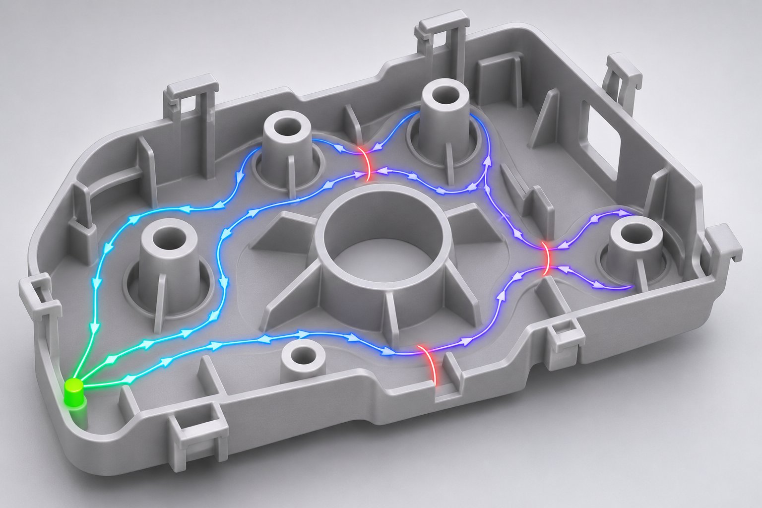
Every feature that forces molten polymer to divide, flow around an obstacle, and reconverge downstream leaves a welding line in its wake. On a simple plaque with a single gate and no obstructions, you might avoid convergence zones entirely. Add a single through-hole, and you've guaranteed at least one weld or knit line on the far side of that hole. Now multiply that by the dozens of features on a typical production part, mounting bosses, snap-fit hooks, ventilation slots, stiffening ribs, core pins, and you begin to see the scale of the challenge.
Here are the most common geometry features and their weld-line consequences:
- Through-holes and core pins: The melt splits around the obstruction and rejoins on the downstream side, creating a weld line that extends from the hole toward the end of fill. The closer the hole sits to the gate, the hotter the melt at reconvergence and the stronger the resulting bond. Holes near end-of-fill produce the weakest weld lines because the fronts arrive cooler and with less packing pressure behind them.
- Bosses: A boss rising from the cavity floor acts much like a core pin, splitting flow and generating a downstream convergence zone. Multiple bosses in close proximity create overlapping flow domains, producing complex weld-line patterns that can be difficult to predict without simulation.
- Ribs and gussets: Ribs oriented perpendicular to the primary flow direction divert melt into side channels. When material fills the rib and re-enters the main flow path, it creates a local convergence. Dense rib fields can generate a web of minor weld lines across the part's backside.
- Abrupt wall-thickness transitions: A sudden step from a thick section to a thin one changes the local flow-front velocity. The melt races through the thick region and hesitates at the thin section, creating uneven arrival times that shift where and at what angle fronts converge. Think of it like a pipeline wrinkle, a local disruption that redirects flow and concentrates stress in an unintended location.
- Windows and slots: Large openings split the melt into two or more streams that must travel long distances before reconverging, often arriving cold and poorly pressurized at the meeting point.
A complex housing with a dozen bosses, several snap features, and a few ventilation slots can easily contain 20 or more weld lines. Eliminating all of them is impossible. Managing them, pushing convergence zones into non-cosmetic, low-stress regions, is the realistic and effective goal.
Gate Type and Placement Strategy
If part geometry determines how many times the melt splits, gate location and type determine where the resulting flow fronts originate and, by extension, where they ultimately collide. Every gate launches its own flow domain, and the boundaries between adjacent domains are inherent weld-line locations.
Multi-gate molds illustrate this most clearly. A two-gate design creates at least one weld line between the two flow domains, regardless of part geometry. A four-gate layout can produce three or more. Each additional gate reduces fill pressure requirements and helps reach thin or distant sections, but it also adds another convergence boundary that must be accounted for.
Gate type matters too. Edge gates, submarine gates, hot-tip gates, and valve gates each impose different constraints on where the entry point can physically sit, how cleanly the gate vestige separates, and whether sequential timing is possible. Valve gates in a hot-runner system, for instance, open the door to sequential filling strategies that can convert multi-gate convergence into a single progressive flow front, a topic covered in more depth later in this article.
Several actionable principles guide gate placement decisions:
- Gate into the thickest section. Material flows from thick to thin, maintaining a hotter melt front longer. Gating into a thin section causes the gate area to freeze before packing pressure can reach thicker downstream regions, producing both sink marks and weaker weld lines.
- Position gates so convergence zones fall in non-critical areas. If a through-hole must sit near a structural boss, locate the gate so the weld line forms on the opposite side of the part, away from the load path and away from cosmetic A-surfaces.
- Consider a single-gate design where feasible. Eliminating the second gate removes one guaranteed weld line. The tradeoff is a longer flow path, which may require higher injection pressure or a slight wall-thickness increase to ensure complete fill.
- Use flow leaders and local thickness adjustments. A shallow channel or a slightly thicker section acts as a highway for the melt, steering the flow front so convergence happens at a wider angle or in a less critical zone. This is one of the simplest and lowest-cost tools for converting a stagnant weld line into a less severe knit line.
The overarching principle is straightforward: a gate-location study, ideally backed by mold-filling simulation, should be a standard pre-tooling step rather than an afterthought. Moving a gate by a few millimeters in CAD is free. Moving it after the mold is cut means welding steel, re-machining, and weeks of delay.
Geometry and gate strategy set up the chessboard. The next move belongs to the process engineer, whose temperature, speed, and pressure settings determine whether the melt arriving at each convergence zone is hot enough and pressurized enough to form a strong bond across the interface.
How to Fix Weld Lines Injection Molding: Process Parameter Control
Geometry and gate placement define where flow fronts converge. Process parameters determine what condition the melt is in when it arrives at those convergence points. A well-placed gate still produces a weak weld if the polymer reaching the interface is too cold, too inhomogeneous, or too poorly pressurized to interdiffuse across the boundary. This is the domain where process engineers have the most immediate leverage, and where understanding each adjustment's tradeoffs separates disciplined optimization from blind trial-and-error.
The challenge isn't knowing which knobs to turn. Most molders intuitively reach for temperature or speed when knitted lines appear. The challenge is knowing the order in which to turn them, how far each lever can realistically move before creating a new problem, and which combinations deliver the strongest weld without collapsing the process window.
Temperature and Speed Adjustments
Three thermal levers influence the injection molding melt temperature weld line relationship: melt temperature, injection speed, and mold surface temperature. Each one affects how hot and fluid the polymer is at the instant two fronts meet, but each one carries distinct tradeoffs.
Melt temperature is the most obvious starting point. A hotter melt retains more thermal energy at the flow front, extending the diffusion window during which polymer chains can reptate across the weld interface. Raising melt temperature by 10-20 degrees Celsius can noticeably improve weld-line appearance and strength, particularly in amorphous resins where the processing-to-Tg gap is tight.
The tradeoff? Push too far and you risk thermal degradation of the polymer, generating volatiles that can actually worsen weld-line bonding by introducing gas pockets at the interface. Degradation also discolors the part, increases cycle time due to the extra heat that must be removed, and raises the risk of flash at the parting line. Experienced troubleshooters recommend treating melt temperature as a secondary lever, raised only in 5-10 degree Celsius increments after other adjustments have been exhausted, specifically because a hotter melt drives off more volatiles that can undermine the very weld you're trying to improve.
Injection speed offers a complementary mechanism. Faster fill delivers the melt front to the convergence zone before as much heat has been lost to the mold walls. The front arrives hotter and with a thinner frozen skin, both of which favor molecular entanglement across the interface. A Taguchi-based optimization study on transparent polycarbonate parts identified fill velocity as one of the two dominant drivers of overall part quality, contributing 25.74% of the total variation in a multi-objective analysis that included weld-line width and dimensional accuracy.
Sounds like a clear win? Not always. Excessive injection speed introduces its own failure modes: jetting, where the melt squirts through the gate and folds over itself rather than advancing as a uniform front; burn marks from adiabatic compression of trapped air; and shear degradation in heat-sensitive resins. The practical sweet spot is the fastest fill rate that still maintains a stable, well-formed flow front without triggering these secondary defects.
Mold surface temperature deserves its own discussion because it operates through a different mechanism than melt temperature or speed. A hotter mold doesn't make the melt hotter at the nozzle; it slows the rate at which heat transfers out of the melt after it enters the cavity. The frozen skin layer grows more slowly, so when two fronts finally converge, the material at each leading edge retains more mobility.
This lever is especially powerful for semi-crystalline resins. Experimental work on PA6 + 30% fiberglass composites showed that raising the mold temperature from room temperature to 153-173 degrees Celsius increased elongation at the weld line from roughly 4.6% to over 12%, a dramatic improvement in ductility. The ultimate tensile strength also improved, though more modestly, rising from 73.4 MPa at room-temperature molding to 76.8 MPa at 173 degrees Celsius. The elongation gains were especially striking because they indicated a fundamentally better molecular connection across the weld interface, not just a surface-level cosmetic improvement.
The cost? Cycle time. A hotter mold takes longer to cool the part to ejection temperature, directly reducing throughput. For applications where weld-line integrity is critical, that tradeoff is often worthwhile. For high-volume commodity parts, it may not be. Rapid heat-cycle techniques, discussed later in this article, offer a way to capture the mold-temperature benefit without a full-cycle penalty.
Packing Pressure and Back Pressure Tradeoffs
Temperature and speed determine the thermal state of the melt at convergence. Packing pressure determines the mechanical force driving material across the weld interface after the fronts have met.
During the packing phase, the screw maintains forward pressure on the melt to compensate for volumetric shrinkage as the polymer cools. At the weld line, this pressure does something even more important: it forces additional molten material from the still-fluid core through the partially frozen interface zone, promoting molecular interdiffusion. Think of it as a hydraulic push that shoves chains from one side of the boundary into the other.
Insufficient packing pressure weld line strength goes hand in hand. When pack pressure is too low, or when the V/P switchover point is set incorrectly, the melt at the weld interface simply sits there and freezes in place without the mechanical driving force needed for chain entanglement. This is one of the most common and most easily corrected process-side contributors to weak weld lines. The Taguchi-GRA study on polycarbonate parts confirmed this quantitatively, identifying holding pressure as the single most dominant factor affecting overall quality, accounting for 26.49% of the observed variation. Research on PA6 + 30% fiberglass echoed the finding: among all parameters studied, packing pressure exhibited the highest standard deviation in UTS values, signaling its outsized influence on weld-line tensile strength.
The ceiling on this lever is set by secondary defects. Excessive pack pressure causes flash at the parting line, overpacking near the gate (leading to high residual stress and warpage), and increased clamp-force requirements. The weld line typically sits far from the gate, so by the time pressure transmits through solidifying material to reach the convergence zone, much of it has been lost. This means the effective packing pressure at the weld is always lower than the set pressure at the machine, and the gap widens as the flow path lengthens or wall thickness decreases.
Back pressure during plasticization is a subtler lever, but it matters. Higher back pressure forces the screw to work harder during recovery, generating more shear heating and mechanical mixing within the melt. The result is a more thermally uniform, better-homogenized shot. Temperature gradients within the melt contribute to uneven flow-front conditions at convergence: if one stream is 10 degrees Celsius hotter than the other, the interface bonding will reflect the colder side's limited mobility. Improving melt homogeneity through back pressure ensures that the entire shot arrives at the weld zone in a consistent thermal state.
Raising back pressure too far introduces its own risks: excessive screw wear, longer recovery times, and potential degradation of shear-sensitive materials. A moderate increase, typically 5-15 bar above minimum, usually provides the best return.
With all these levers in view, the practical question becomes: where do you start? The following sequence ranks process adjustments by their typical effectiveness and ease of implementation, giving you a clear troubleshooting roadmap:
- Raise injection speed. Fastest to implement, delivers hotter melt fronts to the convergence zone with minimal risk of degradation. Monitor for jetting and burn marks as the upper limit.
- Increase mold surface temperature. Slows skin formation at the weld, improving both strength and cosmetics. Accept the cycle-time cost or investigate localized heating options.
- Verify and optimize packing pressure and V/P switchover. Ensure that adequate pressure reaches the weld zone during the packing phase. Adjust the switchover point to avoid premature pressure drop. Check for sufficient packing time.
- Increase back pressure during plasticization. Improves melt homogeneity and temperature uniformity. A low-risk adjustment that supports every other lever on this list.
- Raise melt temperature in small increments. Apply in 5-10 degree Celsius steps only after the above adjustments are optimized. Monitor for degradation signs such as splay, discoloration, or increased volatiles at the weld.
- Improve venting at the weld-line location. Trapped air and volatiles at the convergence point prevent intimate contact between the fronts. Adding or cleaning vents directly at the predicted weld location removes this barrier and often delivers immediate improvement.
The goal of every process adjustment is the same: deliver the hottest, most homogeneous melt possible to the convergence point while maintaining the widest viable process window. A weld line cannot be stronger than the melt conditions at the moment of convergence allow.
Notice that this hierarchy moves from the adjustments with the fewest negative side effects to those requiring the most caution. Injection speed and mold temperature improve weld-line quality with relatively contained tradeoffs. Packing pressure and back pressure are mid-tier levers that require careful balancing. Melt temperature sits last because its side effects, degradation and volatile generation, can directly undermine the weld bond you're trying to strengthen.
Every one of these adjustments, however, carries a hidden assumption: the plasticizing unit is delivering a thermally uniform, well-mixed melt in the first place. A worn screw with degraded compression, a barrel with cold spots, or a check ring that leaks during injection quietly sabotages even the most carefully tuned process settings. The condition of the hardware between the hopper and the nozzle tip sets a baseline that no amount of parameter tweaking can overcome.
Plasticizing Hardware and Melt Quality at the Weld Zone
A process engineer can dial in the perfect melt temperature, optimize injection speed, and tune packing pressure to textbook values. Yet if the screw flights are worn flat, the barrel has uneven heating, or the check ring leaks during injection, the melt arriving at each convergence zone will be inconsistent, poorly mixed, and thermally uneven. The process settings become suggestions rather than instructions, and the weld-line results reflect the hardware's limitations, not the engineer's intent.
This is the gap that most weld-line troubleshooting guides skip entirely. They list parameter adjustments as though the plasticizing unit is a perfect black box. It isn't. Injection molding screw and barrel wear directly undermines the melt quality that every upstream recommendation depends on, and recognizing this connection can save weeks of fruitless process tweaking.
Why Melt Homogeneity Matters at the Weld Interface
Recall the core principle from the process-parameter discussion: you want the hottest, most uniform melt possible reaching the convergence point. Melt homogeneity weld line quality is a direct, cause-and-effect relationship. If the shot contains temperature gradients of even 5-10 degrees Celsius between different flow streams, the cooler front will form a thicker frozen skin and offer less molecular mobility at the interface. The resulting weld takes on the character of the worst-performing stream, not the average.
Where do those temperature gradients come from? Frequently, from the plasticizing unit itself.
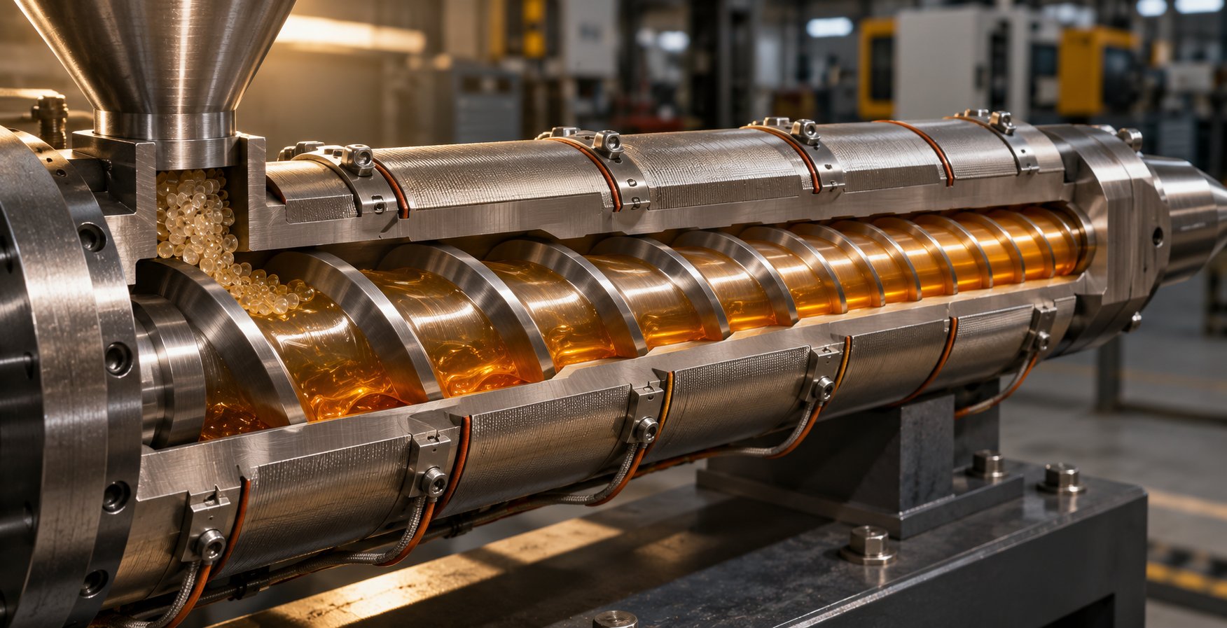
A worn screw with reduced flight depth in the compression zone loses its ability to generate consistent shear heating as resin passes from the feed section to the metering section. Material near the barrel wall may be fully melted while pellets in the screw channel core remain partially solid. These unmelted particles, sometimes visible as specks or streaks in the finished part, concentrate at flow-front convergence zones where they physically block chain-to-chain contact across the interface. Industry troubleshooting data identifies poor melt quality from worn screw flights as a direct cause of visible weld lines, along with inconsistent temperature distribution from worn barrels and uncontrolled material movement from degraded check valves.
Barrel wear compounds the problem differently. As the barrel bore enlarges from abrasion or corrosion, the clearance between screw flight and barrel wall increases. Material slips backward over the flights instead of being positively conveyed forward, reducing the effective compression and shear the resin experiences. Uneven wear along the barrel length also creates localized hot and cold spots where heater bands can no longer maintain a uniform temperature profile. The melt exiting the metering zone carries those thermal inconsistencies all the way to the weld.
Then there's the check ring. During injection, the check ring (or non-return valve) is supposed to seal completely, preventing melt from flowing backward along the screw channel as the screw pushes forward. A worn or damaged check ring seal in injection molding allows backflow during the critical injection and packing phases. The consequences are twofold: the effective shot volume varies from cycle to cycle, producing inconsistent cushion readings, and the packing pressure that's supposed to drive material across the weld interface never fully reaches the convergence zone because pressure is bleeding backward through the leaking valve.
Imagine trying to pressurize a garden hose with a hole in it. You can crank the faucet all the way open, but the water pressure at the nozzle will always disappoint. A leaking check ring does exactly the same thing to your packing pressure at the weld line.
Evaluating and Upgrading Screw and Barrel Condition
The frustrating thing about plasticizing-hardware degradation is that it's gradual. The screw doesn't snap in half one day. It wears incrementally, and the process engineer unconsciously compensates by nudging temperatures up, extending cycle times, or raising pressures. By the time someone investigates the hardware, the process window has been silently shrinking for months.
Several telltale signs point to plasticizing components as a root cause of persistent weld-line problems:
- Inconsistent cushion readings: If the cushion varies by more than 1-2 mm shot to shot with no material or setting changes, the check ring is likely leaking. This directly reduces repeatability of packing pressure at the weld zone.
- Rising reject rates with no mold or material change: When scrap increases gradually over weeks or months despite stable settings, progressive hardware wear is the most common hidden variable.
- Visible streaking, unmelts, or color inconsistency: These are direct evidence of inadequate melting and mixing in the plasticizing unit. If you see them on the part surface, similar inhomogeneities are present inside the weld interface where you can't see them.
- Longer recovery times or inability to maintain backpressure: Worn flights reduce the screw's pumping efficiency, extending plasticization time and limiting the back pressure you can effectively apply.
- Elevated melt temperature at normal settings: Excessive clearance between screw and barrel increases shear in the wrong places, sometimes overheating material locally while leaving other zones under-melted.
When these symptoms appear, inspecting the screw, barrel, and check ring should precede any further process adjustments. Measuring screw flight diameter, barrel bore diameter, and check-ring sealing surfaces against original specifications reveals whether the hardware is still capable of delivering the melt quality your process settings assume.
Beyond wear assessment, screw geometry itself deserves scrutiny. Compression ratio, L/D ratio, flight depth, and mixing-section design should be matched to the resin family and application requirements. A general-purpose screw processing a 30% glass-fiber nylon may deliver adequate results on day one but lack the mixing capability and wear resistance to sustain melt quality over thousands of hours. Barrier screws, mixing screws, and application-specific designs offer meaningfully better melting efficiency and homogeneity for demanding materials.
For molders who identify hardware condition as a contributing factor to weld-line defects, the upgrade path matters as much as the diagnosis. A one-for-one replacement with the same general-purpose screw geometry restores original performance but doesn't address whether that original performance was ever well-suited to the resin and part requirements. NANHAIYA's custom injection molding screw barrels offer a more targeted approach: their technical review evaluates screw geometry, existing wear patterns, melting efficiency, mixing performance, and material-retention concerns specific to each molder's machine, resin, and shot profile. The result is a screw and barrel set engineered around the application rather than pulled off a generic shelf, addressing the root plasticizing variables that influence melt quality at every convergence zone in the cavity.
Whether you pursue a custom solution or a standard replacement, the key plasticizing factors that directly affect weld-line quality should guide your evaluation:
- Melt temperature uniformity: The screw and barrel must deliver a shot with minimal thermal gradients from first shot to last, and from the leading edge to the trailing edge of the melt stream.
- Mixing effectiveness: Adequate dispersive and distributive mixing ensures colorants, additives, and the polymer itself are evenly distributed, preventing localized weak zones at the weld.
- Shot-to-shot consistency: Repeatable shot volume and melt condition ensure that every cycle produces the same weld-line quality, not just the best cycles.
- Material retention and dead spots: Hangup zones in the screw channel or between the screw tip and barrel end cap allow material to degrade thermally. Degraded material eventually flushes into a shot and concentrates at flow-front boundaries, introducing contamination and gas directly at the weld interface.
- Check-ring seal integrity: A clean, consistent seal during injection and packing is non-negotiable for delivering the packing pressure your process settings prescribe to the weld zone.
Think of the plasticizing unit as the foundation beneath every process optimization discussed earlier in this article. Raising injection speed doesn't help if the melt is full of thermal gradients from a worn compression zone. Increasing pack pressure accomplishes nothing if half of it leaks backward through a worn check ring. Elevating mold temperature extends the diffusion window at the interface, but only if the melt arriving there is uniform enough to take advantage of it.
Addressing hardware condition closes the gap between what your process settings promise and what the melt actually delivers. It's the least glamorous intervention on the list, and often the most impactful. With a well-maintained and properly specified plasticizing system in place, every parameter adjustment works as intended, and the conversation can shift from damage control to genuine optimization, including the advanced molding technologies that push weld-line performance beyond what conventional processing can achieve.
Advanced Weld Line Mitigation Technologies
Process optimization and hardware maintenance can push weld-line strength to the limits of what conventional molding allows. But some applications demand more. A Class-A automotive fascia with zero visible convergence marks, a structural bracket in 30% glass-filled nylon where even a relocated weld line can't be tolerated in the load path, or an ultra-thin consumer electronics housing filled through eleven gates that would normally produce ten convergence zones. These are the parts where standard parameter tuning runs out of headroom, and specialized molding technologies take over.
Three families of advanced techniques have proven effective at either eliminating weld lines entirely, relocating them outside the final part geometry, or transforming a stagnant weld into a bond that approaches bulk-material strength. Each comes with real cost and complexity tradeoffs, which is why they're reserved for applications where the stakes justify the investment.
Sequential Valve Gating and Cascade Filling
Imagine a long automotive bumper fascia with six gates feeding the cavity simultaneously. All six flow fronts launch at once, and five convergence zones form wherever adjacent flow domains collide. Every one of those zones is a potential cosmetic blemish and structural weak point. What if, instead of opening all six gates at the same moment, you opened them one at a time, in a carefully timed sequence, so that only a single advancing melt front ever existed inside the cavity?
That's the core idea behind sequential valve gate injection molding, often called SVG or cascade molding. Each valve gate in the hot-runner system is connected to its own actuator and controller. The first gate opens and launches a melt front. As that front passes the location of the second gate, the second gate opens, injecting fresh hot material behind the advancing front rather than against it. The new melt "rejuvenates" the cooling front without creating a head-on collision. The process repeats down the length of the part, gate by gate, producing what is effectively a single continuous flow front with no weld lines between gate zones.
The benefits extend beyond weld-line elimination. Industry experience with SVG has demonstrated clamp-tonnage reductions of 20% to 30% compared to filling through all gates simultaneously, because only a portion of the cavity is under injection pressure at any given moment. Pack and hold can also be profiled with greater precision, supplying longer or more intense packing only to the areas that need it. One early automotive adopter dropped cycle time from 110 seconds to under 75 seconds on a PC/polyester bumper, with most of the savings coming from reduced clamp-force requirements.
Cascade filling does require careful tuning. The distance the melt front travels between gates, the timing of each valve opening and closing, and the melt temperature at each gate tip are all critical parameters. Open the second gate too early, and hot material flows backward toward the still-pressurized first gate, creating flow instabilities. Open it too late, and the surface material from the first gate has already solidified, negating the rejuvenation effect. Gate opening can be triggered by time delay, screw position, or cavity-pressure transducers, with in-cavity sensing offering the most robust feedback loop.
The practical cost? An SVG system typically runs about 15% to 20% more than a standard valve-gate hot runner, primarily for the additional controllers, actuators, and wiring. Flow simulation is strongly recommended during mold design to determine optimal gate positions and actuation timing. Without simulation, tuning an SVG system on the press floor becomes an expensive, iterative exercise.
SVG has found its strongest foothold in automotive applications, including bumpers, fenders, grilles, instrument panels, and door panels. It's also proven valuable in consumer electronics: one notable example involved a notebook computer case with only a 1-mm wall, filled sequentially through eleven gates using a carbon-filled conductive polycarbonate that would not fill at all with a conventional simultaneous-gate system.
Variotherm and Rapid Heat-Cycle Molding
Sequential gating prevents weld lines by controlling where and when flow fronts form. Variotherm molding, also known as rapid heat cycle molding (RHCM), attacks the problem from the opposite direction: it accepts that fronts will converge but ensures the melt-front skin is still molten when they do.
The principle is deceptively simple. Just before injection begins, the mold cavity surface is rapidly heated above the polymer's glass-transition temperature (for amorphous resins) or above its crystallization onset temperature (for semi-crystalline resins). Filling and packing occur against this hot surface, so the fountain-flow skin layer that normally freezes on contact with the mold stays fluid. When two fronts converge, the material at each leading edge retains enough molecular mobility to interdiffuse deeply across the interface, effectively healing the weld. After packing is complete, the mold is rapidly cooled to ejection temperature, and the part is demolded.
The results can be dramatic. A comprehensive review of RHCM research confirmed that raising the cavity surface temperature to near or above the glass-transition temperature consistently eliminates visible weld marks and significantly improves surface gloss. On the structural side, tensile testing showed that RHCM specimens with weld lines had measurably higher strength than conventionally molded specimens with the same weld geometry, while specimens without weld lines showed no discernible difference between the two processes. The researchers attributed the improvement to both a smaller V-notch dimension and a higher bonding strength across the weld interface due to extended chain entanglement at elevated temperature.
One particularly telling experiment removed a thin surface layer containing the V-notch from both RHCM and conventionally molded parts. Thinned specimens with a weld line showed improved tensile strength compared to full-thickness specimens, confirming that the surface notch acts as a stress concentrator independent of the bulk interface quality. RHCM reduces both the notch severity and the interface weakness simultaneously, which is why it outperforms conventional molding so decisively at convergence zones.
Three heating methods dominate commercial variotherm molding weld lines applications:
- Steam heating: Pressurized steam at 160-180 degrees Celsius is circulated through channels in the mold, rapidly raising the cavity surface temperature. Steam offers fast, relatively uniform heating and has been widely adopted for large parts like LCD TV bezels and automotive interior panels. One study achieved a 50% reduction in the mold time constant by optimizing the heating and cooling channel layout with baffles, and the weld marks were completely eliminated once the cavity surface reached approximately 130 degrees Celsius.
- Electromagnetic induction heating: A copper coil positioned near the mold surface generates eddy currents in the steel cavity, heating it from within. Induction systems can raise the surface temperature by over 70 degrees Celsius in just 3-4 seconds, making them well-suited for localized heating of specific weld-line zones rather than the entire cavity. Research using induction-heated ABS molds demonstrated both elimination of surface markings and enhanced weld-line tensile strength.
- Electric cartridge heating: Resistive heating rods embedded in the cavity plate heat the mold conductively. Electric systems offer precise temperature control and are simpler to retrofit into existing molds than steam or induction setups. Studies using cartridge heaters showed that increasing heater power density from 15 to 30 W/cm squared reduced the heating time from 58 seconds to 19 seconds for a 30-to-120 degree Celsius temperature rise.
The undeniable tradeoff is cycle time. Heating the mold surface before every shot and cooling it afterward adds seconds to each cycle, a penalty that compounds across high-volume production runs. Equipment cost is also significant: steam systems require boilers, pressure regulators, and specialized plumbing; induction systems need power supplies and custom coil geometries; electric systems demand high-wattage heaters and precise thermal management. These investments make RHCM most cost-effective for parts where surface quality or weld-line strength justifies the added complexity, such as unpainted automotive exteriors, high-gloss consumer electronics housings, and structural components in fiber-reinforced materials.
Gas-Assisted and Overflow-Well Techniques
Sequential gating and variotherm address weld lines during filling. A third family of techniques deals with weld lines after they form, by physically displacing the compromised material out of the final part geometry.
Gas-assisted injection molding injects nitrogen gas into the melt after the cavity is partially filled. The expanding gas hollows out thick sections and pushes material through the cavity. When engineered specifically for weld-line mitigation, the gas channel can be routed to push the convergence zone into a sacrificial gas passage or into a region that will be cored out. The weld-line material is effectively swept away from the structural cross-section, leaving behind a gas channel wall composed of material that flowed continuously rather than converging head-on.
Overflow wells, sometimes called weld-line traps, take a more direct approach. A small secondary cavity, connected to the main part by a narrow tab, is positioned at the predicted weld-line location. As the two flow fronts converge in the main cavity, the melt doesn't simply stagnate at the interface. Instead, it continues flowing into the overflow well, dragging the poorly bonded, fiber-misaligned material at the interface out of the part and into a sacrificial tab that is later trimmed off.
This continued flow through the weld zone is the key mechanism. A simulation study using Moldex3D demonstrated the effect quantitatively on a 35%-glass-filled nylon 66 tensile bar. A double-gated bar without an overflow well showed a roughly 35% reduction in major modulus (stiffness in the flow direction) at the weld line compared to a single-gated control bar. Adding an offset overflow well recovered much of that loss, reducing the stiffness deficit to just 16% below the control. The overflow well's benefit comes from "underflow," the continued movement of melt through the center of the part after the weld line initially forms. This underflow reorients glass fibers from their unfavorable parallel-to-weld alignment into a flow-direction orientation that actually carries load, while also increasing polymer chain entanglement across the interface.
The overflow well must be sized and positioned carefully. It needs to be large enough that it doesn't fill completely before the weld line forms; otherwise, no underflow occurs. In the Moldex3D study, the overflow tab measured two-thirds of the part's wall thickness and made up about 9% of the overall part volume, though the optimal size varies greatly depending on part geometry. The well should also be located so that end-of-fill occurs inside the tab, not in the main part, confirming that material actually flowed through the weld zone into the sacrificial cavity.
Both gas-assist and overflow wells add features to the mold, either gas channels and injection nozzles or secondary cavities and trim requirements. Their cost is generally lower than SVG or variotherm systems, making them attractive as targeted fixes for specific weld-line locations rather than system-wide investments.
The following table compares these advanced techniques across the factors that matter most when deciding which approach fits a given application:
| Technique | Weld-Line Benefit | Added Cost | Cycle-Time Impact | Best Application Scenario |
|---|---|---|---|---|
| Sequential Valve Gating (SVG) | Eliminates inter-gate weld lines by creating a single progressive flow front; can also reduce clamp tonnage 20-30% | Moderate to High (15-20% over standard valve-gate hot runner, plus controller) | Neutral to Positive (reduced clamp needs can shorten cycles) | Large multi-gated parts (bumpers, fascias, grilles); parts requiring paint-free Class-A surfaces; family molds with unbalanced cavities |
| Variotherm / Rapid Heat Cycle Molding | Dramatically improves molecular bonding and eliminates V-notch at all convergence zones; enhances surface gloss | High (steam boiler, induction power supply, or high-wattage cartridge heaters; specialized mold construction) | Negative (adds heating and extended cooling phases; partially offset by optimized channel design) | High-gloss housings (TVs, monitors, electronics); fiber-reinforced structural parts where weld strength is critical; unpainted automotive exterior panels |
| Gas-Assisted Injection Molding | Displaces weld-line material into sacrificial gas channels; hollows thick sections to reduce weld-line stress | Moderate (gas injection unit, nozzle, and modified mold; design engineering for gas channel routing) | Slightly Negative (gas injection adds a brief phase; offset by faster cooling of hollowed sections) | Parts with thick-to-thin transitions where gas channels can be routed through weld zones; structural parts needing weight reduction |
| Overflow Well (Weld-Line Trap) | Flushes poorly bonded, fiber-misaligned material out of the part into a sacrificial tab; reorients fibers through underflow | Low to Moderate (added cavity volume, runner to tab, and post-mold trimming; no specialized equipment) | Minimal (slightly more material per shot; trimming adds a secondary operation) | Glass-fiber-reinforced parts with unavoidable weld lines at structural locations; targeted fix for specific problem zones without system-level changes |
A few patterns stand out across this comparison. Sequential valve gating is the most versatile solution for multi-gate parts but carries a meaningful upfront investment. Variotherm delivers the most complete weld-line healing but imposes the steepest cycle-time and equipment penalties. Gas assist and overflow wells represent targeted, lower-cost interventions best suited for specific problem zones rather than system-wide defect prevention.
In practice, these technologies are rarely deployed in isolation. An automotive interior panel might use SVG for cascade filling combined with localized induction heating at a single critical convergence point, plus an overflow well on a hidden tab where a through-hole generates an unavoidable weld in a snap-fit zone. The optimal combination depends on the part's geometry, material, cosmetic requirements, structural demands, and production volume, variables that are almost impossible to evaluate by intuition alone.
This is precisely where mold-filling simulation becomes indispensable. Predicting where weld lines will form, what convergence angle they'll exhibit, and how hot the melt will be at each interface, all before a single block of steel is cut, transforms these advanced technologies from expensive experiments into engineered solutions with predictable outcomes.
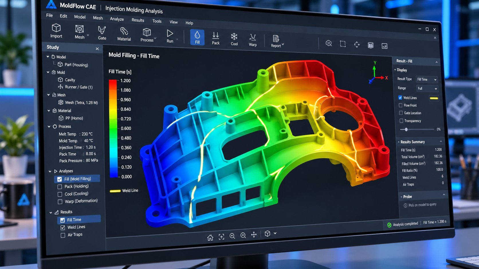
Using Simulation to Predict and Prevent Weld Lines
Every mitigation strategy discussed so far, from gate repositioning to sequential valve gating to variotherm heating, shares a common dependency: someone has to know where the weld lines will form, how severe they'll be, and whether a proposed design change actually improves the outcome before the mold is built. Guessing gets expensive fast. A single gate relocation on a hardened production mold can cost tens of thousands of dollars and weeks of lead time. Mold-filling simulation eliminates that gamble by letting engineers predict weld line location during mold filling, iterate on solutions digitally, and commit to steel only when the results meet acceptance criteria.
Surprisingly, most practical guides on weld lines injection molding barely mention simulation, or treat it as an afterthought. In reality, it's the single highest-leverage tool in the entire prevention toolkit, precisely because it multiplies the effectiveness of every other strategy.
Predicting Weld Line Locations Before Cutting Steel
Modern injection molding simulation platforms, including Autodesk Moldflow, Moldex3D, and Cadmould, work by solving the coupled equations of fluid flow, heat transfer, and polymer rheology across a meshed representation of the part cavity, runner system, and cooling channels. The software tracks each advancing melt front through the cavity, recording its position, temperature, pressure, and velocity at every time step. When two fronts converge, the solver flags the location and calculates the meeting angle between them.
That meeting angle is the critical output. As discussed earlier in this article, convergence below roughly 135-145 degrees produces a true weld line with poor molecular bonding, while wider angles yield knit or meld lines with progressively better strength retention. Moldex3D's 2026 release, for example, uses a 145-degree threshold to automatically distinguish between sharp weld lines and meld lines, and allows users to adjust this cutoff interactively to explore how sensitive the results are to the chosen boundary.
But location and angle are just the starting point. The simulation outputs most relevant to injection molding simulation weld lines assessment include:
- Fill-time contours: Color-mapped animations showing how the cavity fills over time. These reveal which areas fill last, where flow fronts stall, and how the filling pattern changes with different gate positions. Areas that fill last are often where the weakest weld lines form, because the melt has lost the most thermal energy by that point.
- Flow-front temperature maps: These display the melt temperature at the leading edge of each flow front as it advances through the cavity. A front arriving at a convergence zone at 240 degrees Celsius will bond far better than one arriving at 200 degrees Celsius. Temperature maps let you quantify this difference and identify which weld locations are thermally compromised.
- Weld-line location markers: Dedicated result overlays that plot every convergence point on the part geometry, often with color coding to indicate severity based on meeting angle or front temperature. Recent algorithm improvements in platforms like Moldex3D dynamically track the fusion process across multiple flow stages and consolidate scattered convergence indicators into continuous line segments, giving engineers a clearer picture of each weld line's full extent.
- Air-trap predictions: Locations where converging fronts trap air or volatiles are flagged automatically. These often coincide with weld lines, and confirming their presence tells the mold designer exactly where to add or enlarge vents.
- Weld-line strength predictions: The latest simulation releases incorporate real-time physical properties of the melt at convergence, including temperature, pressure, and shear rate, to estimate the relative strength of each weld. Moldex3D 2026 demonstrated that different materials produce different weld-line strength profiles even under identical processing parameters, enabling more precise material-selection decisions during the design phase.
What makes this truly powerful is the iterative workflow. You run a baseline simulation, identify problem weld lines, adjust the gate location or add a flow leader in the CAD model, re-run the analysis, and compare results. A gate move that took weeks and thousands of dollars in physical tooling takes minutes in software. Research on automated gate optimization has taken this concept even further, coupling Moldflow's fill analysis with genetic-algorithm-based optimization to automatically search for the gate position that places the weld line in the lowest-stress region of the part. In one aerospace bracket study, this simulation-driven approach doubled the structural strength of the final component by ensuring the weld line formed away from highly loaded areas.
The same study revealed a striking detail: when the weld line coincided with the maximum equivalent stress zone, bracket strength dropped by 56% in mechanical testing. Relocating the gate so the weld fell in a low-stress region, guided entirely by simulation, eliminated that loss. The calculation results and experimental fracture data showed good agreement, validating that the digital prediction translated reliably to physical performance.
Integrating Simulation into a Weld Line Prevention Hierarchy
Simulation doesn't replace material selection, process tuning, hardware maintenance, or advanced molding technologies. It orchestrates them. Knowing where each weld line will form and how severe it will be lets you apply the right mitigation at the right location, avoiding both under-engineering (accepting a dangerous weld) and over-engineering (deploying expensive variotherm heating where a simple gate shift would suffice).
Here's the complete weld line prevention injection molding hierarchy, ordered from highest impact and lowest cost to highest cost and most specialized application:
- Design optimization through simulation (geometry and gate placement): This is the highest-leverage, lowest-cost intervention when performed early. Use moldflow weld line simulation to evaluate gate locations, runner balancing, wall-thickness adjustments, and flow-leader placement. Every weld line you eliminate or convert to a knit line at this stage is one you'll never need to fight on the production floor. The cost of a simulation license and engineering time is a fraction of a single mold modification.
- Material selection: Choose resins with inherently better weld-line tolerance for parts where convergence zones are unavoidable in load-bearing areas. Unfilled semi-crystalline polymers heal weld interfaces far more effectively than amorphous or heavily filled grades. If structural requirements demand fiber reinforcement, consider lower fiber loadings where the design allows, or select resins with lower melt viscosity to improve interdiffusion.
- Process parameter tuning: Optimize injection speed, mold temperature, melt temperature, and packing pressure to deliver the hottest, most pressurized melt possible to each convergence point. These adjustments are the most accessible levers for the process engineer and yield meaningful improvements, especially when simulation has already placed weld lines in the most favorable locations.
- Hardware maintenance and upgrades: Ensure the plasticizing unit, screw, barrel, and check ring, delivers a thermally uniform, well-mixed melt. No amount of parameter optimization overcomes a worn compression zone or a leaking non-return valve. Periodic inspection and replacement, or upgrade to application-specific screw geometries, closes the gap between intended and actual melt quality.
- Advanced molding technologies: Deploy sequential valve gating, variotherm / rapid heat cycle molding, gas-assisted injection, or overflow wells for applications where steps one through four cannot achieve the required weld-line performance. These carry the highest cost and complexity but deliver results that conventional processing simply cannot match, including complete elimination of visible weld marks and near-bulk-strength bonding across fiber-reinforced interfaces.
The most cost-effective weld-line strategy addresses the defect in the design phase, not on the production floor. Every dollar spent on simulation-guided optimization before steel is cut saves ten or more in mold rework, scrap, and field failures downstream.
You'll notice the hierarchy mirrors a familiar engineering principle: the earlier in the development cycle you address a problem, the cheaper and more effective the solution. A gate relocation in CAD is essentially free. The same change after mold construction requires welding, re-machining, re-texturing, and re-qualification. Deploying variotherm heating to compensate for a gate position that simulation could have corrected months earlier is not a technical failure, but it is an economic one.
The most robust approach combines multiple layers of this hierarchy. Simulation-guided design places weld lines in the least damaging locations. Material selection ensures those weld lines retain the maximum possible strength. Process tuning squeezes every last degree of temperature and every bar of packing pressure into the convergence zone. Well-maintained plasticizing hardware guarantees that the melt quality assumptions behind those process settings actually hold, cycle after cycle. And for the rare convergence zones that remain critical after all other interventions, advanced technologies deliver the final margin of safety.
No single technique solves the weld-line challenge across all applications. But a structured, simulation-informed strategy, one that treats each convergence zone as a design variable rather than an inevitable defect, consistently produces parts that are stronger, more cosmetically uniform, and less costly to manufacture than those where weld lines are discovered and fought only after the mold arrives on the shop floor.
Frequently Asked Questions About Weld Lines in Injection Molding
1. What is the difference between a weld line and a knit line in injection molding?
The key difference is the convergence angle at which two melt fronts meet. A weld line forms when fronts collide at an included angle below roughly 135 degrees, leaving minimal opportunity for molecular interdiffusion and resulting in the weakest bond. A knit line forms above that threshold, where fronts merge at a shallower angle and continue flowing together, allowing more polymer chain entanglement. Meld lines sit at the gentlest end of the spectrum, near or above 140-150 degrees, where strength loss becomes negligible. Mold designers can sometimes convert a problematic weld line into a less severe knit line by repositioning the gate or adding flow leaders to widen the convergence angle.
2. How much strength do weld lines lose compared to the base material?
Strength retention at a weld line varies dramatically by polymer type and filler content. Unfilled semi-crystalline resins like PP and PA6 can retain roughly 80-96% of their bulk tensile strength, making the weld primarily a cosmetic concern. Amorphous unfilled resins such as ABS and PMMA typically retain around 50-60%. The most severe losses occur in glass-fiber-reinforced compounds: PA6-GF30 may drop to 34-55% of base strength because fibers align parallel to the weld plane instead of bridging across it, effectively eliminating the reinforcement at the interface.
3. How can mold-filling simulation help prevent weld line defects?
Simulation software like Autodesk Moldflow or Moldex3D models advancing flow fronts and flags exactly where they converge, the meeting angle at each location, and the melt-front temperature. Engineers can then iterate on gate positions, runner balancing, wall thickness, and flow leaders in CAD before any steel is cut. Recent platforms even estimate relative weld-line strength using real-time melt properties at convergence. Research has shown that simulation-guided gate optimization can double structural performance by ensuring the weld line forms away from high-stress zones, at a fraction of the cost of post-tooling modifications.
4. Can worn screws and barrels make weld lines worse?
Yes. A worn screw with reduced flight depth delivers thermally uneven melt containing partially unmelted particles that concentrate at flow-front convergence zones, blocking molecular bonding. A degraded check ring leaks melt backward during injection and packing, reducing the effective pressure that drives material across the weld interface. Barrel wear creates localized hot and cold spots that add temperature gradients to the shot. These hardware issues silently undermine every process-parameter optimization, so inspecting and upgrading plasticizing components, including application-matched screw geometries, is essential for consistent weld-line quality.
5. What advanced molding technologies can eliminate or improve weld lines?
Four main technologies address weld lines beyond standard process tuning. Sequential valve gating opens gates in a timed sequence to create a single progressive flow front, eliminating inter-gate weld lines entirely. Variotherm or rapid heat cycle molding heats the mold surface above the polymer's glass-transition temperature before filling, keeping the melt-front skin molten at convergence for deep molecular interdiffusion. Gas-assisted injection pushes weld-line material into sacrificial gas channels. Overflow wells flush poorly bonded material into a trimmed-off secondary cavity while reorienting fibers through continued underflow. Each method adds cost and complexity, so they are typically reserved for critical cosmetic or structural applications.
Written by
Nanhaiya Technical Team
Zhoushan Nanhaiya Plastic Machinery Co., Ltd.
The Nanhaiya technical team supports screw and barrel manufacturing projects through application review, technical communication, custom manufacturing coordination, and production and quality control.
Discuss Your Application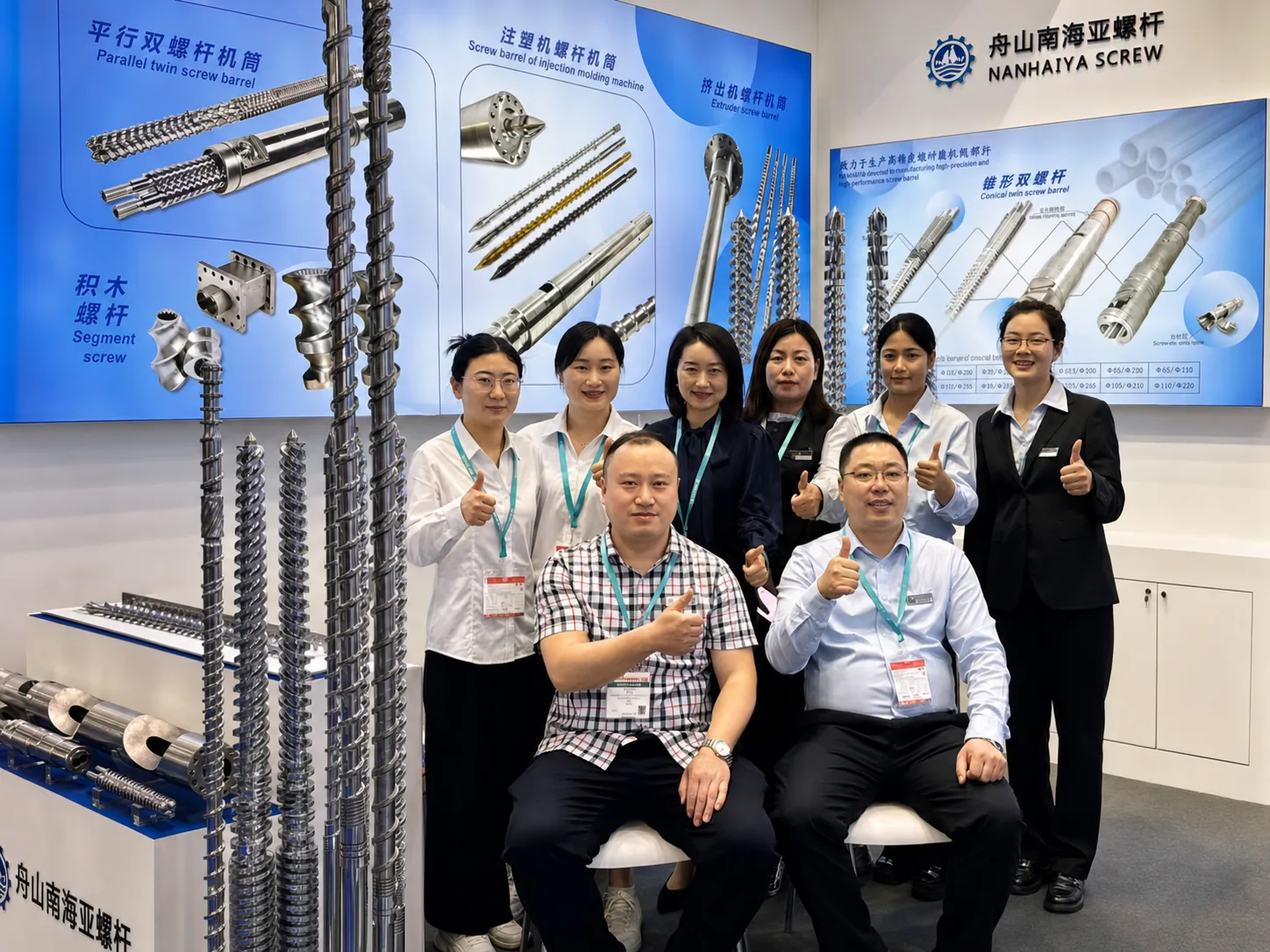
Related Articles
More insights on screw barrel technology and plastics processing.
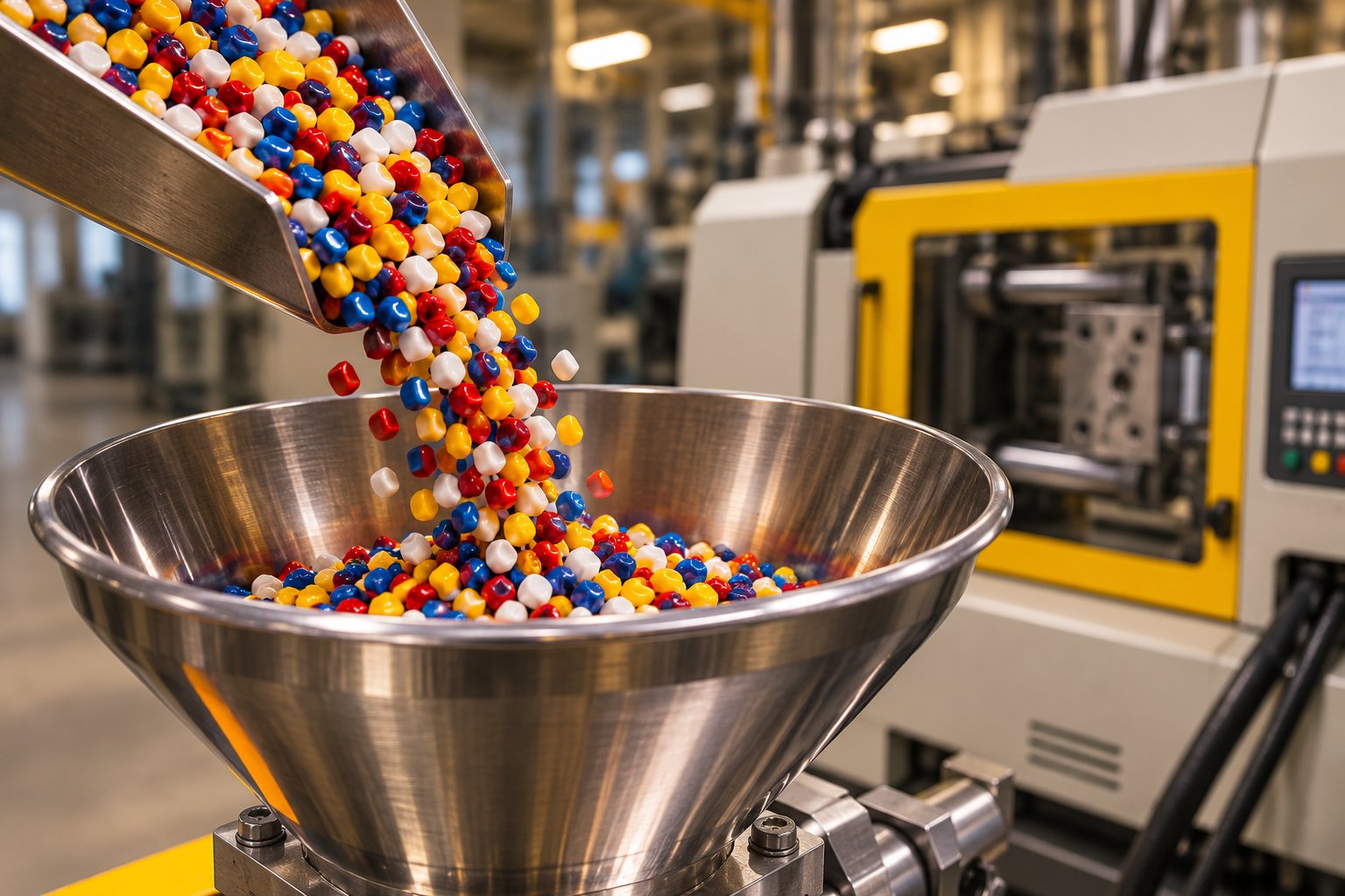
Injection Molding Color Mixing: From Streaks to Flawless Consistency
Nov 19, 2026
Master injection molding color mixing with expert guidance on colorant types, screw design, process parameters, defect troubleshooting, and Delta E QC protocols.
Read Article
Wrong Extruder Breaker Plate? Spot the Signs Before Scrap Piles Up
Nov 19, 2026
Learn how to select, size, and maintain your extruder breaker plate. Covers hole geometry, pressure drop, polymer-specific specs, and troubleshooting tips.
Read Article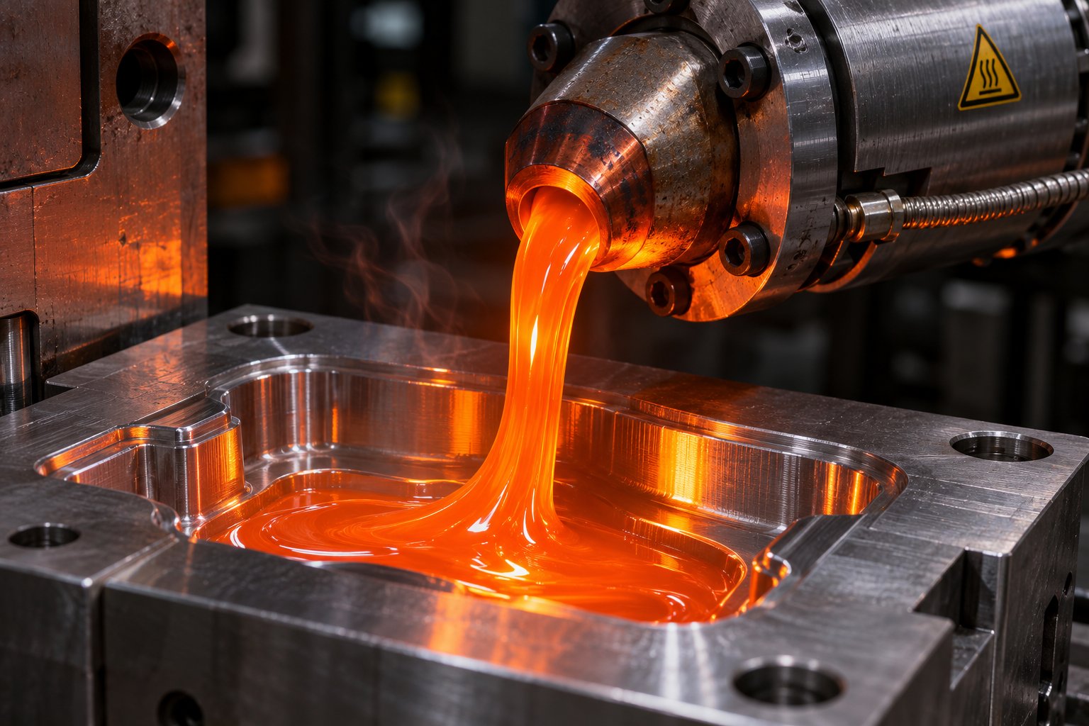
Injection Molding Melt Temperature: Why Your Barrel Settings Lie
Nov 19, 2026
Learn why barrel set points lie about injection molding melt temperature. Complete resin chart, measurement methods, defect troubleshooting, and optimization steps.
Read ArticleLooking for something else?
Search by material, symptom or product and jump straight to the relevant page.
These are navigation suggestions based on keyword matching — not a quotation, not a delivery commitment, and not a substitute for engineering review. Final specification is confirmed by our engineers against your drawings and processed material.
Need help with screw barrel selection?
Share your machine model, processed material and application. Our team can help with pricing and technical support.